Electric Vehicle Strategies - Accurate Technologies
23
Electric Vehicle Strategies Implementing electric vehicle strategies ACCURATE TECHNOLOGIES
Transcript of Electric Vehicle Strategies - Accurate Technologies

Copyright © 2016
Confidential
Electric Vehicle Strategies
Implementing electric vehicle
strategies
ACCURATE TECHNOLOGIES

▪ Overview
▪ Software architecture design
▪ Functional requirements
▪ Baseline Strategy
▪ EV Controls
▪ Miscellaneous information
▪ Example Applications
Outline
Overview (1/2)
▪ Pi Innovo has developed control systems for
electric vehicle architectures
▪ Simulink® strategies for these applications
provide an efficient starting point for other
electric vehicle projects
▪ The strategies form a starting point
for prototyping as well as production
activities Electric Vehicle Architecture
M560 as
a. VCU
b. CCS

Document Map
Unit Level
Software Verification Specification
Styleguide
RP-11
DP-8
RP-7ref[tsr_xxx_nnn]
IP-5
TP-4
TP-10
TP-16
Note: Items appended to PR tag are considerations made during the peer review process.
Note: Items appended to a work product are considerations made in the authoring of the work product.
RP-9
DP-12
IP-8
TP-17 TP-18
Software Safety Requirementsdef[tsr_xxx_nnn]
ref[sys_xxx_nnn]
System Requirements
Software Unit Design / Functional Requirements
Software Architectural Design
Source Code
Test Results
No definitions
ref[fct_xxx_nnn]def[fct_xxx_nnn]
ref[fcr_xxx_nnn]
Integration
Software Verification SpecificationTest Results
Software Verification Plan
def[sys_xxx_nnn]
Reference to TBD
Architecture and Dataflow Review
def[arc_xxx_nnn]
ref[sys_xxx_nnn]
def[fcr_xxx_123]
ref[arc_xxx_nnn]
No definitions
ref[fit_xxx_nnn]def[fit_xxx_nnn]
ref[arc_xxx_nnn]
Software Verification Report
Modeling & Style Review
Diagnostic Fault Summary
No def
ref[fcr_xxx_nnn]
No def
No ref
No def
No ref
PR
PR
PR
PR
PR
PR
PR
PR
PR
PR Peer Review
Traceability Reports
PR
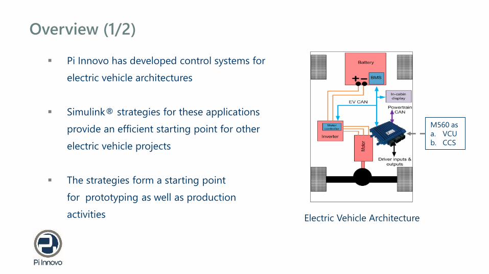
Overview (2/2)
▪ Top level architecture is contained in
two documents
▪ Control Architecture Document
(~45 pages)
▪ Functional Block Diagram
▪ Architecture documentation
describes the high level
functionality, requirements and
interfaces
Software architecture design

Functional Requirements
Requirements Tags
16 Software Components: Varying size and complexity 8-15 pages each
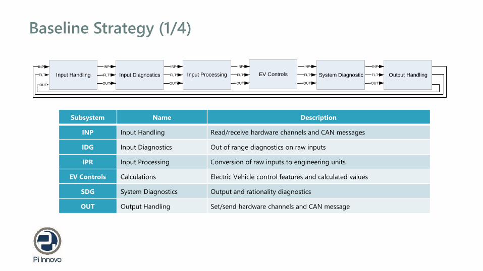
Baseline Strategy (1/4)
Input Handling Input Diagnostics EV Controls System Diagnostic Output Handling
INP
FLT
OUT
INP
FLT
OUT
INP
FLT
OUT
INP
FLT
OUT
INP
FLT
OUT
Input Processing
INP
FLT
OUT
Subsystem Name Description
INP Input Handling Read/receive hardware channels and CAN messages
IDG Input Diagnostics Out of range diagnostics on raw inputs
IPR Input Processing Conversion of raw inputs to engineering units
EV Controls Calculations Electric Vehicle control features and calculated values
SDG System Diagnostics Output and rationality diagnostics
OUT Output Handling Set/send hardware channels and CAN message

Baseline Strategy (2/4)
INP Input Handling▪ This feature is responsible for reading all input signals
▪ Inputs include:
▪ Analog signals from external sensors and OpenECU internal monitors
▪ Digital signals from external sensors and OpenECU internal monitors
▪ CAN input messages from all CAN buses
OUT Output Handling▪ Responsible for receiving commands from other
subsystems via the output bus
▪ Set output blocks of wired components to the correct value
▪ Transmit CAN messages to ECUs on CAN network
▪ Transmit UART messages to the secondary micro
▪ Set internal signals of the VCU
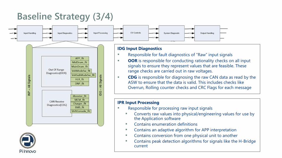
Baseline Strategy (3/4)
IDG Input Diagnostics
▪ Responsible for fault diagnostics of “Raw” input signals
▪ OOR is responsible for conducting rationality checks on all input
signals to ensure they represent values that are feasible. These
range checks are carried out in raw voltages.
▪ CDG is responsible for diagnosing the raw CAN data as read by the
ASW to ensure that the data is valid. This includes checks like
Overrun, Rolling counter checks and CRC Flags for each message
IPR Input Processing
▪ Responsible for processing raw input signals
▪ Converts raw values into physical/engineering values for use by the Application software
▪ Contains enumeration definitions
▪ Contains an adaptive algorithm for APP interpretation
▪ Contains conversion from one physical unit to another
▪ Contains peak detection algorithms for signals like the H-Bridge current
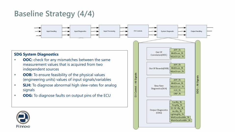
Baseline Strategy (4/4)
SDG System Diagnostics
▪ OOC: check for any mismatches between the same
measurement values that is acquired from two
independent sources
▪ OOB: To ensure feasibility of the physical values
(engineering units) values of input signals/variables
▪ SLH: To diagnose abnormal high slew-rates for analog
signals
▪ ODG: To diagnose faults on output pins of the ECU

EV Controls
SPC: Set Point Calculation
SSC: Start-up Shut-down Control
MIT: Mitigating actions
TCU: Transmission Control Unit
SCS: Supervisory Control System
MCS: Motor Control Strategy
THC: Thermal Control
LIT: Lighting Controls
DSP: Display Control

EV Controls – Sample use-case: Logic
▪ SPC = Reads pedal analog inputs, considers gear position, brake pedal, faults
and creates a final driver demanded torque request
▪ SCS = Torque arbitration and Vehicle Mode determination. Implements
multiple torque strategies to Creates a final torque request based on multiple
sources
▪ MCS= Units that create final torque request to the Traction Motor(s)

EV Controls - Sample use-case: Simulink
Pedal
Volts
Driver
Demand NmDesired
Torque NmMotor CAN
Commands
SPC SCS MCS

EV Controls - Features
SPC Set Point Calculation▪ SPC uses the accelerator pedal
position signal and converts it into a torque percentage request
▪ Via individual look up tables depending on switch states
▪ Collects torque requests from multiple sources, combining them to create a single overall driver demand
SSC Startup Shutdown Sequencing▪ Consists logic acting as software enabler for MCU relays
▪ It provides startup and shut down routines for the EV▪ It includes hard shutdown (emergency stop push) or a soft
shutdown
▪ SSC broadcasts startup/shutdown state of the vehicle
▪ Also handles the power supply hold feature
MIT Mitigation Actions
▪ Used to address functional safety
requirements of the vehicle in the
longitudinal direction
▪ If vehicle operation mode is unsafe set to degraded state
by limiting upper Torque % limit and command Brake
controller
▪ This feature can be tied in with Torque security
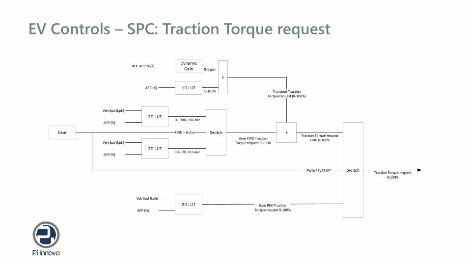
EV Controls – SPC: Traction Torque request
2D LUT
Dynamic Gain
Veh Spd (kph)
APP (%)
ROC APP (%/s)
0-100%, Hi Gear
x
Transient TractionTorque request (0-100%)
1D LUTAPP (%)0-100%
0-1 gain
+
2D LUT
Veh Spd (kph)
APP (%)0-100%, Lo Gear
SwitchBase FWD Traction
Torque request 0-100%
Gear FWD – Hi/LoTraction Torque request
FWD 0-100%
Switch
2D LUT
Veh Spd (kph)
APP (%)
Base REV Traction Torque request 0-100%
FWD/REVERSE?Traction Torque request
0-100%

EV Controls – SPC: Regen Torque request
2D LUT
Veh Spd (kph)
APP (%)0-100%, Hi Gear
2D LUT
Veh Spd (kph)
APP (%)0-100%, Lo Gear
SwitchGear FWD – Hi/Lo
2D LUT
Veh Spd (kph)
BPP (%)0-100%, Hi Gear
2D LUT
Veh Spd (kph)
BPP (%)0-100%, Lo Gear
SwitchFWD – Hi/Lo
+Regen Torque request
0-100%
Set to calibratable value for REV if so desired otherwise set to 0%

EV Controls – MIT: Torque Security (sample use-case)
2 AIN1 full-slope, 1 half-slope
1 5v Vref1 SigRtn
Main Micro
DISC
RET
EIN
PU
TS
DIS
CR
ETE
OU
TPU
TS
Diagnostics
Range & Rationality
CO
MM
S R
x
Diagnostics
CRCMsg Couter
Control
Floating point,
autocoded Simulink
UART Tx
Command
Secondary Micro
Diagnostics
Range & Rationality
Diagnostics
CRCMsg Couter
Control
Fixed point, hand coded
C
Enable / Disable
Logic
UART
CAN Txcvr Dsbl
CO
MM
S T
x
Fault Manager
UART
Platform Software
Platform Software
APPMCU
GCU
M
M
Traction Motor
Generator
Vehicle CAN buses
CAN Rx Signals
+ P-R-N-H-L+ Brake pedal position
+Vehicle Speed
GPA Fuel Position (AIN)
Main Gearbox Pos (AIN)
Mid Gearbox Pos (AIN)
M
M
Main Gear Position Actuator
Mid Gear Position Actuator
Brake Switch (DIN)
DC/DC Current Sens (AIN)
MCU Relay
GCU Relay
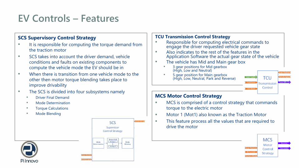
EV Controls – Features
SCS Supervisory Control Strategy
▪ It is responsible for computing the torque demand from
the traction motor
▪ SCS takes into account the driver demand, vehicle
conditions and faults on existing components to
compute the vehicle mode the EV should be in
▪ When there is transition from one vehicle mode to the
other then motor torque blending takes place to
improve drivability
▪ The SCS is divided into four subsystems namely ▪ Driver Final Demand
▪ Mode Determination
▪ Torque Calculations
▪ Mode Blending
MCS Motor Control Strategy
▪ MCS is comprised of a control strategy that commands
torque to the electric motor
▪ Motor 1 (Mot1) also known as the Traction Motor
▪ This feature process all the values that are required to
drive the motor
TCU Transmission Control Strategy▪ Responsible for computing electrical commands to
engage the driver requested vehicle gear state▪ Also indicates to the rest of the features in the
Application Software the actual gear state of the vehicle▪ The vehicle has Mid and Main gear box
▪ 3 gear positions for Mid gearbox (High, Low and Neutral)
▪ 5 gear position for Main gearbox (High, Low, Neutral, Park and Reverse)
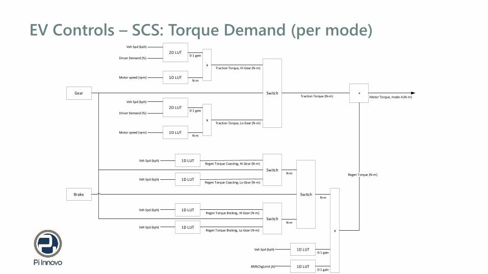
EV Controls – SCS: Torque Demand (per mode)2D LUT
1D LUT
2D LUT
1D LUT
Veh Spd (kph)
Driver Demand (%)
Motor speed (rpm)
0-1 gain
N-m
0-1 gain
N-m
x
x
Traction Torque, Hi Gear (N-m)
Veh Spd (kph)
Driver Demand (%)
Motor speed (rpm)
Traction Torque, Lo Gear (N-m)
1D LUT
1D LUT
Veh Spd (kph)Regen Torque Coasting, Hi Gear (N-m)
Veh Spd (kph)Regen Torque Coasting, Lo Gear (N-m)
1D LUT
1D LUT
Veh Spd (kph)Regen Torque Braking, Hi Gear (N-m)
Veh Spd (kph)Regen Torque Braking, Lo Gear (N-m)
Gear
Brake
Switch
Switch
Switch
Switch
N-m
N-m
1D LUTVeh Spd (kph)0-1 gain
N-m
x
1D LUTBMSChgLimit (A)0-1 gain
Traction Torque (N-m)
Regen Torque (N-m)
+Motor Torque, mode A (N-m)

EV Controls – SCS: Torque blending
Traction Torque (N-m)
Regen Torque (N-m)
+Motor Torque, mode A (N-m)
Traction Torque (N-m)
Regen Torque (N-m)
+Motor Torque, mode B (N-m)
Traction Torque (N-m)
Regen Torque (N-m)
+Motor Torque, mode C (N-m)
Mode Arbitration
Motor Torque
DemandRaw (N-m)
CAN Message from MCU
Actual Motor Torque(N-m)
a
b
Gear Shift = TRUE ?
Rate limit allowable change of Final Torque Demand (N-m/s)
Input for Gear position
Yes
a
b
Actual Torque > Calibration Threshold ?
No
Monitor Actual Motor Torque
Final Motor Torque Demand (N-m)
= Motor Torque Demand Raw
(N-m)
No
a
Yes
Final Motor Torque
Demand (N-m)
Final Motor Torque
Demand (N-m)
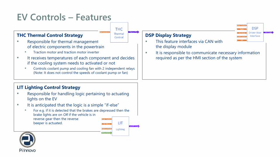
EV Controls – Features
THC Thermal Control Strategy
▪ Responsible for thermal management
of electric components in the powertrain▪ Traction motor and traction motor inverter
▪ It receives temperatures of each component and decides
if the cooling system needs to activated or not▪ Controls coolant pump and cooling fan with 2 independent relays
(Note: It does not control the speeds of coolant pump or fan)
LIT Lighting Control Strategy
▪ Responsible for handling logic pertaining to actuating
lights on the EV
▪ It is anticipated that the logic is a simple “if-else”▪ For e.g. if it is detected that the brakes are depressed then the
brake lights are on OR if the vehicle is in
reverse gear then the reverse
beeper is actuated.
DSP Display Strategy
▪ This feature interfaces via CAN with
the display module
▪ It is responsible to communicate necessary information
required as per the HMI section of the system

Miscellaneous information
Din IgnKeyDbnc _ C
Prefix
Variable Type
Descriptive Section
Named item type Type letter
Displayable signals (no type letter)
Calibration scalars C
Calibration maps M
Constants SC
Arrays CA
### Build information:
..Strategy memory:
602592 bytes of strategy/code memory used
1756704 bytes remaining
..Calibration memory:
70836 bytes of calibration memory used (rough indication,
includes Simulink support data)
61259 bytes remaining
..Workspace memory:
264902 bytes of workspace/displayable memory used,
including
188 bytes of adaptive data, and
4278 bytes of diagnostic trouble code data, and
8192 bytes of model stack
259385 bytes remaining
CPU utilization < 50% on
M560 (SPC5764)
Variable naming convention
Pi Innovo is the expert partner for the design and development of innovative
electronics systems to the automotive, transportation, defense, industrial, and
aviation industries. Our uniquely adaptable business engagements, based on
Pi Team services and OpenECU products, enjoy a strong reputation for delivering
the highest quality results , providing outstanding value for our clients.
OpenECU is a wide range of adaptable, field-ready products and
intellectual property designed to accelerate electronics system
development. The philosophy behind OpenECU is the creation of
modular, reusable technology that is implemented to volume
production standards and is fully “open” to custom
configuration, adaption and further development.
ACCURATE TECHNOLOGIES