Electric vehicle control system based on CAN bus
12
Acta Technica 62 No. 1A/2017, 541–552 c 2017 Institute of Thermomechanics CAS, v.v.i. Electric vehicle control system based on CAN bus Han Peng 1 Abstract. The purpose of this paper is to develop a theoretical basis for improving electric vehicle control system which based on controller area network (CAN) bus. Based on the CANOPEN protocol, electric vehicle control system was analyzed, which mainly focused on DS301and DS302 sub protocol. The method is to design a electric vehicle control system of by CANOPEN network. Then, strategy for electric vehicle control was studied and operation mode and working condition of electric vehicle was concluded. Finally, hardware and software systems of electric vehicle control system were designed. Mainly, hardware concerning flyback power supply and main controller were debugged. Modular method was adopted when designing software. Software was classified into five modules to design according to its function. The experimental results show that the electric vehicle system based on CAN bus is suitable for the development of both hardware and software. Based on the above finding, it is concluded that electric vehicle control system was improved to a certain extend. Key words. Electric vehicle, CAN bus, control system. 1. Introduction Transportation is more and more convenient with the rapid development of au- tomobile industry in recent years. However, more and more environment and energy issues are emerging [1], which interferes heavily in the quality of people’s lives. For example, some regions in the world are instable and global economy development is influenced because of unbalanced petroleum distribution. Besides, automobile industry account for a large proportion of the world’s greenhouse gases because a large amount of fossil fuel is assumed. Moreover, vehicle emissions such as res- pirable suspended particulates, carbon monoxide and oxynitride would increase the incidence of respiratory disease [2–3]. For these reasons, electric vehicle is needed. Comparing with traditional vehicle, electric vehicle has many advantages, such as environmental-friendly, easy to drive, high efficiency, and low noise. There are no engine, transmission and exhaust system. Besides, electric vehicle can charge in off-peak hours of power demand, which can reduce power shortage in peak hours [4]. 1 School of Mechanical Engineering, North China University of Water Resource and Electric Power, Zhengzhou, 450045, China http://journal.it.cas.cz
Transcript of Electric vehicle control system based on CAN bus
Acta Technica 62 No. 1A/2017, 541–552 c© 2017 Institute of Thermomechanics CAS, v.v.i.
Electric vehicle control system basedon CAN bus
Han Peng1
Abstract. The purpose of this paper is to develop a theoretical basis for improving electricvehicle control system which based on controller area network (CAN) bus. Based on the CANOPENprotocol, electric vehicle control system was analyzed, which mainly focused on DS301and DS302sub protocol. The method is to design a electric vehicle control system of by CANOPEN network.Then, strategy for electric vehicle control was studied and operation mode and working conditionof electric vehicle was concluded. Finally, hardware and software systems of electric vehicle controlsystem were designed. Mainly, hardware concerning flyback power supply and main controller weredebugged. Modular method was adopted when designing software. Software was classified into fivemodules to design according to its function. The experimental results show that the electric vehiclesystem based on CAN bus is suitable for the development of both hardware and software. Basedon the above finding, it is concluded that electric vehicle control system was improved to a certainextend.
Key words. Electric vehicle, CAN bus, control system.
1. Introduction
Transportation is more and more convenient with the rapid development of au-tomobile industry in recent years. However, more and more environment and energyissues are emerging [1], which interferes heavily in the quality of people’s lives. Forexample, some regions in the world are instable and global economy developmentis influenced because of unbalanced petroleum distribution. Besides, automobileindustry account for a large proportion of the world’s greenhouse gases because alarge amount of fossil fuel is assumed. Moreover, vehicle emissions such as res-pirable suspended particulates, carbon monoxide and oxynitride would increase theincidence of respiratory disease [2–3]. For these reasons, electric vehicle is needed.Comparing with traditional vehicle, electric vehicle has many advantages, such asenvironmental-friendly, easy to drive, high efficiency, and low noise. There are noengine, transmission and exhaust system. Besides, electric vehicle can charge inoff-peak hours of power demand, which can reduce power shortage in peak hours [4].
1School of Mechanical Engineering, North China University of Water Resource and ElectricPower, Zhengzhou, 450045, China
http://journal.it.cas.cz
542 HAN PENG
Electric vehicle can be dated back to 1880s, which developed rapidly until 1920.Since 1920s, electric vehicle is gradually replaced by automobile because more andmore petroleum was exploited and there are more and more studies about automo-bile. However, since 1950s, electric vehicle industry was attached great importanceagain because more attention was paid to oil crisis, environmental protection andrational used of energy [5]. Electric vehicle is a complex systematic engineering,which needs a reliable control system with superior performance to comprehensivelycoordinate and control the work of various components [6]. Therefore, study ondesign of electric vehicle control system is of great important to the development ofelectric vehicle technology. Many scholars at home and abroad have studied electricvehicle control system.
For example, a new controller is researched and developed [7], which can be usedto reduce vibration by disturbing observer and enhance stability of power trans-mission system of electric vehicle using electrical machine. The control slip rate ofelectric vehicle with changing parameters was controlled by sliding-mode [8]. Basedon Nissan LEAF blade electric vehicles (BEV), Kawamura and his partners inte-grated its two forward gears to set dynamic model and economic model [9]. Differentdriving control strategies for three models were designed based on different drivingconditions [10]. The strategy for automatic mode identification is studied based onfuzzy control system. Thus, electric vehicle control system based on CAN bus wasto be studied to improve control system [11].
2. Materials and methods
2.1. Application of CANOPEN protocol in electric vehicle
For those electric vehicles in use, several electronic control units are controlled bymain controller through CAN bus [12], for example, electric machine, ABS/ESP unit,automotive dashboard, battery controllers, air conditioner controller, and controllersof door, window and windshield wiper. In common, electric vehicle bus is made upof two or three CAN bus. A high-speed CAN bus is used to connect main controllerto electric machine driver while one or two other low-speed CAN buses are usedcommunication between main controller and low-speed signals. Thus, for the systemstudied only two electric machines were controlled by main controller through CANbus (see Fig. 1) and the other parts will be worked out in the future work.
Basic CANOPEN network is built according to DS301 sub protocol of CANOPENprotocol, which is able to distribute identifier, establish object dictionary, initializeSDO and PDO communication objects, and establish state machine and manage-ment objects of NMT network. However, with the most basic network functions,this network was unable to meet requirements of complex system. Thus, start-upprocedures of CANOPEN network was designed based on DS302 sub protocol ofCANOPEN protocol and electric machine control protocol stack was built basedon DS402 sub protocol of CANOPEN protocol for the application of CAN bus toelectric vehicle.
DS301 sub protocol defines state machine for network management and ways

ELECTRIC VEHICLE CONTROL SYSTEM 543
Fig. 1. CAN Bus structure of electric vehicle
to switch node network state. Simple systems such as vo module can be start-upwith this procedure while complex system such as electric machine driver, shouldbe start-up with an improved start-up procedure to ensure all nodes were started-up safely. Under CANOPEN protocol, main engine need to reset communicationof sub-ordinate computer before starting up sub-ordinate computer node. Stateof sub-ordinate computer node should be checked by NMT main machine beforesending instruction to reset communication [13] because equipment such as machinecontroller would enter a special working mode similar to manual mode when NMTmain engine suddenly lost connection.
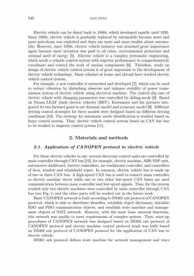
Figure 2 shows start-up procedure of CANOPEN network based on DS302 subprotocol. Configuration audit for software version under DS302 sub protocol wasignored because network structure of this system was simple. Currently, the systemstudied controlled two cooperative-working electric machine controllers whose sub-ordinate computer node was set as necessary and states need to be reviewed beforestart-up when configuration network.
2.2. Electric vehicle control strategy
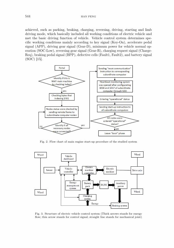
Electric vehicle control system was made up of several components and sub-systems, including electric machine controller, energy management system (EMS),vehicle control system, accelerator pedal and brake pedal. This control system wasbased on vehicle control unit, which transmits and exchanges information with CANbus. Figure 3 shows structure of the vehicle control system.
Electric vehicle has four gears, which operation can be classified into such fivemodes with the used of accelerator pedal and brake pedal as neutral position, nor-mal driving pattern, braking mode, failure mode for protection and start mode [14].After processing signals of key, pedal, gears and signals of other sensors accordingto control strategy, electric vehicle controller identified the corresponding model andpassed the corresponding instruction into corresponding control unit to control thevehicle accordingly. According to those five models, seven working conditions can be
544 HAN PENG
achieved, such as parking, braking, charging, reversing, driving, starting and limbdriving mode, which basically included all working conditions of electric vehicle andmet the basic driving function of vehicle. Vehicle control system determines spe-cific working conditions mainly according to key signal (Key-On), accelerate pedalsignal (APP), driving gear signal (Gear-D), minimum power for vehicle normal op-eration (SOC-Low), reversing gear signal (Gear-R), charging request signal (Charge-Req), braking pedal signal (BPP), defective cells (Fault1, Fault2), and battery signal(SOC) [15].
Fig. 2. Flow chart of main engine start-up procedure of the studied system
Fig. 3. Structure of electric vehicle control system (Thick arrows stands for energyflow; thin arrow stands for control signal; straight line stands for mechanical joint)
ELECTRIC VEHICLE CONTROL SYSTEM 545
3. Experimental results and discussion
3.1. Hardware design for electric vehicle control
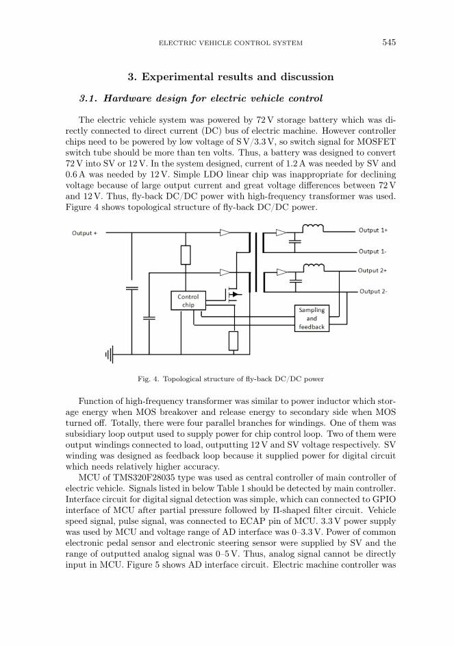
The electric vehicle system was powered by 72V storage battery which was di-rectly connected to direct current (DC) bus of electric machine. However controllerchips need to be powered by low voltage of SV/3.3V, so switch signal for MOSFETswitch tube should be more than ten volts. Thus, a battery was designed to convert72V into SV or 12V. In the system designed, current of 1.2A was needed by SV and0.6A was needed by 12V. Simple LDO linear chip was inappropriate for decliningvoltage because of large output current and great voltage differences between 72Vand 12V. Thus, fly-back DC/DC power with high-frequency transformer was used.Figure 4 shows topological structure of fly-back DC/DC power.
Fig. 4. Topological structure of fly-back DC/DC power
Function of high-frequency transformer was similar to power inductor which stor-age energy when MOS breakover and release energy to secondary side when MOSturned off. Totally, there were four parallel branches for windings. One of them wassubsidiary loop output used to supply power for chip control loop. Two of them wereoutput windings connected to load, outputting 12V and SV voltage respectively. SVwinding was designed as feedback loop because it supplied power for digital circuitwhich needs relatively higher accuracy.
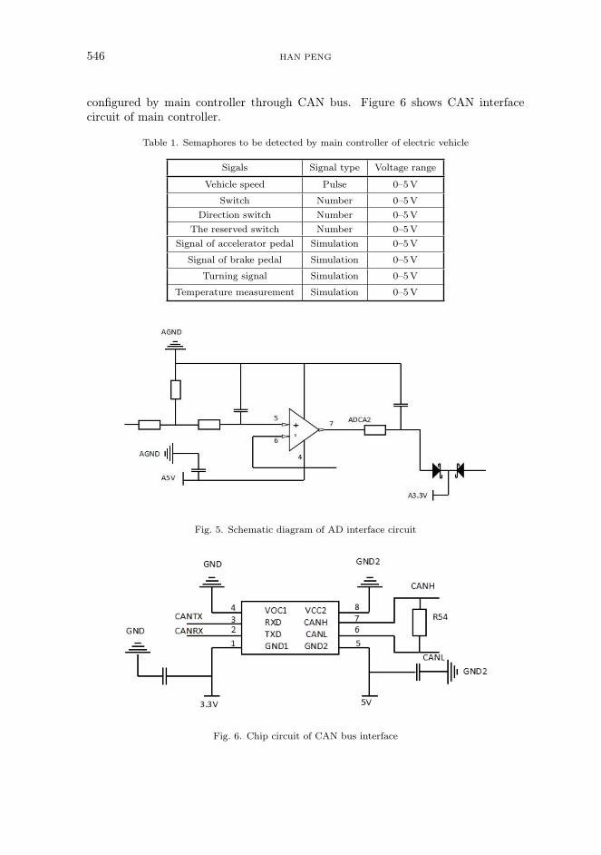
MCU of TMS320F28035 type was used as central controller of main controller ofelectric vehicle. Signals listed in below Table 1 should be detected by main controller.Interface circuit for digital signal detection was simple, which can connected to GPIOinterface of MCU after partial pressure followed by Π-shaped filter circuit. Vehiclespeed signal, pulse signal, was connected to ECAP pin of MCU. 3.3V power supplywas used by MCU and voltage range of AD interface was 0–3.3V. Power of commonelectronic pedal sensor and electronic steering sensor were supplied by SV and therange of outputted analog signal was 0–5V. Thus, analog signal cannot be directlyinput in MCU. Figure 5 shows AD interface circuit. Electric machine controller was
546 HAN PENG
configured by main controller through CAN bus. Figure 6 shows CAN interfacecircuit of main controller.
Table 1. Semaphores to be detected by main controller of electric vehicle
Sigals Signal type Voltage range
Vehicle speed Pulse 0–5V
Switch Number 0–5VDirection switch Number 0–5V
The reserved switch Number 0–5VSignal of accelerator pedal Simulation 0–5V
Signal of brake pedal Simulation 0–5V
Turning signal Simulation 0–5V
Temperature measurement Simulation 0–5V
Fig. 5. Schematic diagram of AD interface circuit
Fig. 6. Chip circuit of CAN bus interface

ELECTRIC VEHICLE CONTROL SYSTEM 547
3.2. Software design for electric vehicle control system
Software was of great importance for vehicle controller because all parts of ve-hicle were controlled by software. Different modules were used to design softwareaccording to software functions. Based on different functions, software of vehiclecontroller was classified into such three hierarchies as management, executive andinterface. Figure 7 shows hierarchy structure.
Fig. 7. Software overall structures
Main program was the key of software design, which was used to identify workingstatus of vehicle according to collected operational information and real-time statusof vehicle. Figure 8 shows flow chart of main program.
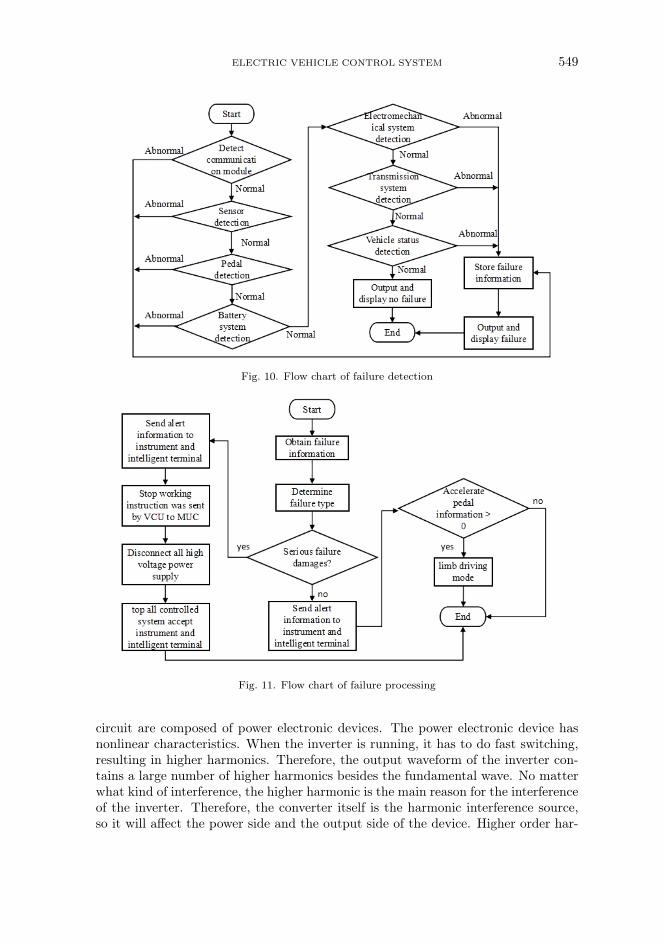
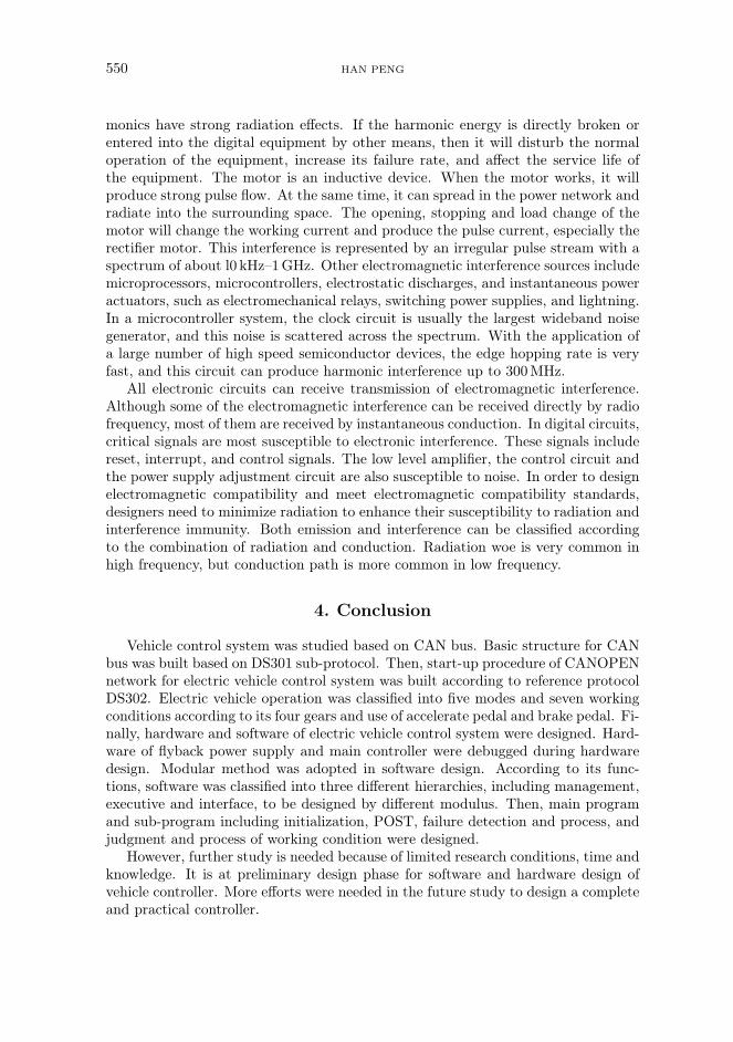
Subprogram design, power-on-self-test (POST), fault detect, failure process, andjudgment and process of working conditions were tackled in subprogram design.First, all modules of controller should be initialized before operating procedures.Figure 9 shows specific modules’ content and initializing sequence. POST was neededafter initialization and following Fig. 10 shows POST flow chart. To ensure security,fault detection was made for all parts of system and Fig. 11 shows failure detectionflow chart. If it detected failures, failure process was needed. If there are no failures,it moves to judgment and process for work condition. Vehicle working conditionwas determined according to collected operation information and real-time status ofall parts of vehicle. Then, corresponding instructions were given to control normaloperation of vehicle.
3.3. Design of electromagnetic compatibility (EMC)
Frequency converter and motor are two serious electromagnetic interference sourcesof electric vehicle. The frequency converter consists of two parts, the main loop and

548 HAN PENG
Fig. 8. Flow chart of main program
Fig. 9. Flow chart of POST
the control loop. The main circuit of frequency converter is mainly composed of rec-tifier circuit, inverter circuit and control circuit, in which rectifier circuit and inverter
ELECTRIC VEHICLE CONTROL SYSTEM 549
Fig. 10. Flow chart of failure detection
Fig. 11. Flow chart of failure processing
circuit are composed of power electronic devices. The power electronic device hasnonlinear characteristics. When the inverter is running, it has to do fast switching,resulting in higher harmonics. Therefore, the output waveform of the inverter con-tains a large number of higher harmonics besides the fundamental wave. No matterwhat kind of interference, the higher harmonic is the main reason for the interferenceof the inverter. Therefore, the converter itself is the harmonic interference source,so it will affect the power side and the output side of the device. Higher order har-
550 HAN PENG
monics have strong radiation effects. If the harmonic energy is directly broken orentered into the digital equipment by other means, then it will disturb the normaloperation of the equipment, increase its failure rate, and affect the service life ofthe equipment. The motor is an inductive device. When the motor works, it willproduce strong pulse flow. At the same time, it can spread in the power network andradiate into the surrounding space. The opening, stopping and load change of themotor will change the working current and produce the pulse current, especially therectifier motor. This interference is represented by an irregular pulse stream with aspectrum of about l0 kHz–1GHz. Other electromagnetic interference sources includemicroprocessors, microcontrollers, electrostatic discharges, and instantaneous poweractuators, such as electromechanical relays, switching power supplies, and lightning.In a microcontroller system, the clock circuit is usually the largest wideband noisegenerator, and this noise is scattered across the spectrum. With the application ofa large number of high speed semiconductor devices, the edge hopping rate is veryfast, and this circuit can produce harmonic interference up to 300MHz.
All electronic circuits can receive transmission of electromagnetic interference.Although some of the electromagnetic interference can be received directly by radiofrequency, most of them are received by instantaneous conduction. In digital circuits,critical signals are most susceptible to electronic interference. These signals includereset, interrupt, and control signals. The low level amplifier, the control circuit andthe power supply adjustment circuit are also susceptible to noise. In order to designelectromagnetic compatibility and meet electromagnetic compatibility standards,designers need to minimize radiation to enhance their susceptibility to radiation andinterference immunity. Both emission and interference can be classified accordingto the combination of radiation and conduction. Radiation woe is very common inhigh frequency, but conduction path is more common in low frequency.
4. Conclusion
Vehicle control system was studied based on CAN bus. Basic structure for CANbus was built based on DS301 sub-protocol. Then, start-up procedure of CANOPENnetwork for electric vehicle control system was built according to reference protocolDS302. Electric vehicle operation was classified into five modes and seven workingconditions according to its four gears and use of accelerate pedal and brake pedal. Fi-nally, hardware and software of electric vehicle control system were designed. Hard-ware of flyback power supply and main controller were debugged during hardwaredesign. Modular method was adopted in software design. According to its func-tions, software was classified into three different hierarchies, including management,executive and interface, to be designed by different modulus. Then, main programand sub-program including initialization, POST, failure detection and process, andjudgment and process of working condition were designed.
However, further study is needed because of limited research conditions, time andknowledge. It is at preliminary design phase for software and hardware design ofvehicle controller. More efforts were needed in the future study to design a completeand practical controller.
ELECTRIC VEHICLE CONTROL SYSTEM 551
References
[1] M.Sarancha: An analysis of regional strategies and programs in the framework ofthe development of automobile tourism in the Central Federal District. Universities forTourism and Service Association Bulletin 9 (2015), No. 1, 34–41.
[2] E.Magaril, R.Magaril: Improving the environmental and performance character-istics of vehicles by introducing the surfactant additive into gasoline. EnvironmentalScience & Pollution Research 23 (2016), No. 17, 17049–17057.
[3] I. J. Lu, S. J. Lin, C. Lewis: Decomposition and decoupling effects of carbon dioxideemission from highway transportation in Taiwan, Germany, Japan and South Korea.Energy policy 35 (2007), No. 6, 3226–3235.
[4] J. Peng, H.He, W.Liu, H.Guo: Hierarchical control strategy for the cooperativebraking system of electric vehicle. Scientific World Journal (2015), No. 4, ID 584075.
[5] Y.Wang, L.H.Hui, B. Liu: The study of intelligent scheduling algorithm in thevehicle ECU based on CAN bus. Open Cybernetics & Systemics Journal 9 (2015),No. 1, 1461–1465.
[6] H.Zhao, G. F. Li, N.H.Wang, S. L. Zheng, L. J. Yu, Y.Gao: Research status ofseveral key technologies for the development of electric vehicles. Applied Mechanicsand Materials 160 (2012), No.Chapter 3, 361–365.
[7] J.M.Rodriguez, R.Meneses, J.Orus: Active vibration control for electric vehiclecompliant drivetrains. Annual Conference of the IEEE Industrial Electronics Soci-ety (IECON), 10–13 November 2013, Vienna, Austria, IEEE Conference Publications(2013), 2590–2595.
[8] T.Goggia, A. Sorniotti, L. de Novellis, A. Ferrara, P.Gruber,J. Theunissen, D. Steenbeke, B.Knauder, J. Zehetner: Integral slidingmode for the torque-vectoring control of fully electric vehicles: Theoretical design andexperimental assessment. IEEE Transactions on Vehicular Technology 64 (2015),No. 5, 1701–1715.
[9] C.Lv, J. Zhang, Y. Li, Y.Yuan: Mode-switching-based active control of powertrainsystem with nonlinear backlash and flexibility for electric vehicle during regenerativedeceleration. Institution of Mechanical Engineers, Part: D, Journal of AutomobileEngineering 229 (2015), No. 11, 1429–1442.
[10] Y.Chen, W.Liu, Y.Yang, W.Chen: Online energy management of plug-in hybridelectric vehicles for prolongation of all-electric range based on dynamic programming.Mathematical Problems in Engineering (2015), ID 368769.
[11] H.Wang, Q. Song, S.Wang, P. Zeng: Dynamic modeling and control strategy op-timization for a hybrid electric tracked vehicle. Mathematical Problems in Engineering(2015), ID 251906.
[12] J.Wang, Q.N.Wang, P.Y.Wang, J.N.Wang, N.W. Zou: Hybrid electric vehi-cle modeling accuracy verification and global optimal control algorithm research. Inter-national Journal of Automotive Technology 16 (2015), No 3, 513–524.
[13] D.Guilbert, M.Guarisco, A.Gaillard, A.N’Diaye, A.Djerdir: FPGA basedfault-tolerant control on an interleaved DC/DC boost converter for fuel cell electric ve-hicle applications. International Journal of Hydrogen Energy 40 (2015), No. 45, 15815to 15822.
[14] C.X. Song, F.Xiao, S.X. Song, S. L. Peng, S.Q. Fan: Stability control of 4WDelectric vehicle with in-wheel motors based on integrated control of electro-mechanicalbraking system. Applied Mechanics and Materials 740, (2015), No.Chapter 3, 206–210.
[15] B.Weeks, J. Xu, B.Cao, Q. Li, Q.Yang: Compound-type hybrid energy storagesystem and its mode control strategy for electric vehicles. Journal of Power Electronics15 (2015), No. 3, 849–859.
Received June 6, 2017

552 HAN PENG