Elcometer 456 Coating Thickness Gauge - korrosjonsteknikk.no
68
English Elcometer 456 3 Coating Thickness Gauge Standard Models Operating Instructions
Transcript of Elcometer 456 Coating Thickness Gauge - korrosjonsteknikk.no

Eng
lish
ge
s
Op_456_3_English.book Page -1 Thursday, January 22, 2009 8:05 PM
Elcometer 4563
Coating Thickness Gau
Standard Models
Operating Instruction

Eng
lish
models:
Equipmen g Patents:FNF UK Pa 86522F1 2 UK Pa 6,762,603F1 2 Germa
This 93/68/EEC.
Bluetooth S
® and Bl ometer Ltd.
All other tra
© CopyrightAll rights res ibed, stored (in a retrieval system orotherwise) o echanical, magnetic, optical, manualor otherwiseA copy of th lcometer.com/downloads.
Doc.No. TMA-0423 Issue 06Text with Cover No: 20242
Op_456_3_English.book Page 0 Thursday, January 22, 2009 8:05 PM
R
These instructions apply to the following Elcometer 4563
Ferrous (F), Non-Ferrous (NF) and Dual Ferrous/Non-Ferrous (FNF)
t described in these instructions is covered by the followintent No: GB2306009B FNF US Patent No: 58tent No: 2367135B F1 2 US Patent No. USn Patent Pending
product meets the emc directive 89/336/EEC, amended 92/31/EEC and
IG QDID = B009627.
and are registered trademarks of Elcometer Ltd.
uetooth® are trademarks owned by Bluetooth SIG Inc and licensed to Elc
demarks acknowledged.
Elcometer Ltd. 2004-2009.erved. No part of this Document may be reproduced, transmitted, transcrr translated into any language, in any form or by any means (electronic, m) without the prior written permission of Elcometer Ltd.is Instruction Manual is available for download on our Website via www.e

R
1
Page. . . . . . . . . . . . . . . . . . . . . . . . 4. . . . . . . . . . . . . . . . . . . . . . . . 5. . . . . . . . . . . . . . . . . . . . . . . . 5. . . . . . . . . . . . . . . . . . . . . . . . 6. . . . . . . . . . . . . . . . . . . . . . . . 6. . . . . . . . . . . . . . . . . . . . . . . . 6. . . . . . . . . . . . . . . . . . . . . . . . 7. . . . . . . . . . . . . . . . . . . . . . . . 7. . . . . . . . . . . . . . . . . . . . . . . . 7. . . . . . . . . . . . . . . . . . . . . . . . 8. . . . . . . . . . . . . . . . . . . . . . . . 9. . . . . . . . . . . . . . . . . . . . . . . . 9. . . . . . . . . . . . . . . . . . . . . . . 10. . . . . . . . . . . . . . . . . . . . . . . 10. . . . . . . . . . . . . . . . . . . . . . . 11. . . . . . . . . . . . . . . . . . . . . . . 12. . . . . . . . . . . . . . . . . . . . . . . 12. . . . . . . . . . . . . . . . . . . . . . . 12. . . . . . . . . . . . . . . . . . . . . . . 13
Op_456_3_English.book Page 1 Thursday, January 22, 2009 8:05 PM
CONTENTS
Section1 About your gauge . . . . . . . . . . . . . . . . . . . . . . . . . . . . . . . . . . . . . . . 1.1 Features . . . . . . . . . . . . . . . . . . . . . . . . . . . . . . . . . . . . . . . . . . . . . . . . 1.2 Standards . . . . . . . . . . . . . . . . . . . . . . . . . . . . . . . . . . . . . . . . . . . . . . . 1.3 What this box contains . . . . . . . . . . . . . . . . . . . . . . . . . . . . . . . . . . . . . 1.4 Conventions in these instructions . . . . . . . . . . . . . . . . . . . . . . . . . . . . 1.5 Quick-start . . . . . . . . . . . . . . . . . . . . . . . . . . . . . . . . . . . . . . . . . . . . . . 2 Getting started . . . . . . . . . . . . . . . . . . . . . . . . . . . . . . . . . . . . . . . . . . 2.1 Fitting the batteries . . . . . . . . . . . . . . . . . . . . . . . . . . . . . . . . . . . . . . . 2.2 Battery condition. . . . . . . . . . . . . . . . . . . . . . . . . . . . . . . . . . . . . . . . . . 2.3 Fitting probes . . . . . . . . . . . . . . . . . . . . . . . . . . . . . . . . . . . . . . . . . . . . 2.4 The controls . . . . . . . . . . . . . . . . . . . . . . . . . . . . . . . . . . . . . . . . . . . . . 2.5 Switching the gauge on . . . . . . . . . . . . . . . . . . . . . . . . . . . . . . . . . . . . 2.6 Switching the gauge off . . . . . . . . . . . . . . . . . . . . . . . . . . . . . . . . . . . . 2.7 The screen . . . . . . . . . . . . . . . . . . . . . . . . . . . . . . . . . . . . . . . . . . . . . . 2.8 Selecting a language . . . . . . . . . . . . . . . . . . . . . . . . . . . . . . . . . . . . . . 2.9 Interfaces . . . . . . . . . . . . . . . . . . . . . . . . . . . . . . . . . . . . . . . . . . . . . . . 3 Taking a reading . . . . . . . . . . . . . . . . . . . . . . . . . . . . . . . . . . . . . . . . 3.1 Before you start . . . . . . . . . . . . . . . . . . . . . . . . . . . . . . . . . . . . . . . . . . 3.2 Procedure . . . . . . . . . . . . . . . . . . . . . . . . . . . . . . . . . . . . . . . . . . . . . .

. . . . . . . . . . . . . . . . . . . . . . . 13
. . . . . . . . . . . . . . . . . . . . . . . 13
. . . . . . . . . . . . . . . . . . . . . . . 14
. . . . . . . . . . . . . . . . . . . . . . . 15
. . . . . . . . . . . . . . . . . . . . . . . 18
. . . . . . . . . . . . . . . . . . . . . . . 23
. . . . . . . . . . . . . . . . . . . . . . . 23
. . . . . . . . . . . . . . . . . . . . . . . 24
. . . . . . . . . . . . . . . . . . . . . . . 25
. . . . . . . . . . . . . . . . . . . . . . . 26
. . . . . . . . . . . . . . . . . . . . . . . 30
. . . . . . . . . . . . . . . . . . . . . . . 31
. . . . . . . . . . . . . . . . . . . . . . . 31
. . . . . . . . . . . . . . . . . . . . . . . 31
. . . . . . . . . . . . . . . . . . . . . . . 32
. . . . . . . . . . . . . . . . . . . . . . . 32
. . . . . . . . . . . . . . . . . . . . . . . 34
. . . . . . . . . . . . . . . . . . . . . . . 34
. . . . . . . . . . . . . . . . . . . . . . . 35
. . . . . . . . . . . . . . . . . . . . . . . 35
. . . . . . . . . . . . . . . . . . . . . . . 37
. . . . . . . . . . . . . . . . . . . . . . . 38
. . . . . . . . . . . . . . . . . . . . . . . 39
Op_456_3_English.book Page 2 Thursday, January 22, 2009 8:05 PM
R
2
4 The reading screen and menus . . . . . . . . . . . . . . . . . . . . . . . . . . . . 4.1 Reading screen . . . . . . . . . . . . . . . . . . . . . . . . . . . . . . . . . . . . . . . . . . 4.2 Main MENU . . . . . . . . . . . . . . . . . . . . . . . . . . . . . . . . . . . . . . . . . . . . . 4.3 Main MENU - Extended menu off . . . . . . . . . . . . . . . . . . . . . . . . . . . . 4.4 Main MENU - Extended menu on . . . . . . . . . . . . . . . . . . . . . . . . . . . . 5 Calibration adjustment . . . . . . . . . . . . . . . . . . . . . . . . . . . . . . . . . . . 5.1 Calibration method . . . . . . . . . . . . . . . . . . . . . . . . . . . . . . . . . . . . . . . . 5.2 Preset calibration methods . . . . . . . . . . . . . . . . . . . . . . . . . . . . . . . . . 5.3 Calibration foils and standards . . . . . . . . . . . . . . . . . . . . . . . . . . . . . . . 5.4 Calibration adjustment procedure . . . . . . . . . . . . . . . . . . . . . . . . . . . . 6 Statistics . . . . . . . . . . . . . . . . . . . . . . . . . . . . . . . . . . . . . . . . . . . . . . . 6.1 Enlarge stats . . . . . . . . . . . . . . . . . . . . . . . . . . . . . . . . . . . . . . . . . . . . 6.2 Stats on LCD . . . . . . . . . . . . . . . . . . . . . . . . . . . . . . . . . . . . . . . . . . . . 6.3 Clear stats . . . . . . . . . . . . . . . . . . . . . . . . . . . . . . . . . . . . . . . . . . . . . . 6.4 Select stats . . . . . . . . . . . . . . . . . . . . . . . . . . . . . . . . . . . . . . . . . . . . . 6.5 Set NDFT . . . . . . . . . . . . . . . . . . . . . . . . . . . . . . . . . . . . . . . . . . . . . . . 6.6 Display . . . . . . . . . . . . . . . . . . . . . . . . . . . . . . . . . . . . . . . . . . . . . . . . . 7 Batching . . . . . . . . . . . . . . . . . . . . . . . . . . . . . . . . . . . . . . . . . . . . . . . 7.1 Exit batching . . . . . . . . . . . . . . . . . . . . . . . . . . . . . . . . . . . . . . . . . . . . 7.2 Open new batch . . . . . . . . . . . . . . . . . . . . . . . . . . . . . . . . . . . . . . . . . . 7.3 Open existing batch . . . . . . . . . . . . . . . . . . . . . . . . . . . . . . . . . . . . . . . 7.4 Review batches . . . . . . . . . . . . . . . . . . . . . . . . . . . . . . . . . . . . . . . . . . 7.5 Set limits . . . . . . . . . . . . . . . . . . . . . . . . . . . . . . . . . . . . . . . . . . . . . . .

R
3
. . . . . . . . . . . . . . . . . . . . . . . 39
. . . . . . . . . . . . . . . . . . . . . . . 40
. . . . . . . . . . . . . . . . . . . . . . . 40
. . . . . . . . . . . . . . . . . . . . . . . 40
. . . . . . . . . . . . . . . . . . . . . . . 42
. . . . . . . . . . . . . . . . . . . . . . . 42
. . . . . . . . . . . . . . . . . . . . . . . 45
. . . . . . . . . . . . . . . . . . . . . . . 45
. . . . . . . . . . . . . . . . . . . . . . . 45
. . . . . . . . . . . . . . . . . . . . . . . 47
. . . . . . . . . . . . . . . . . . . . . . . 48
. . . . . . . . . . . . . . . . . . . . . . . 49
. . . . . . . . . . . . . . . . . . . . . . . 52
. . . . . . . . . . . . . . . . . . . . . . . 52
. . . . . . . . . . . . . . . . . . . . . . . 53
. . . . . . . . . . . . . . . . . . . . . . . 54
. . . . . . . . . . . . . . . . . . . . . . . 61
. . . . . . . . . . . . . . . . . . . . . . . 63
Op_456_3_English.book Page 3 Thursday, January 22, 2009 8:05 PM
7.6 Free memory . . . . . . . . . . . . . . . . . . . . . . . . . . . . . . . . . . . . . . . . . . . . 8 Transferring readings to a computer . . . . . . . . . . . . . . . . . . . . . . . . 8.1 Transferring Using a Cable . . . . . . . . . . . . . . . . . . . . . . . . . . . . . . . . . 8.2 Transferring Using a Bluetooth® connection . . . . . . . . . . . . . . . . . . . . 8.3 Transferring PSPC readings data to ElcoMaster . . . . . . . . . . . . . . . . . 9 Probes . . . . . . . . . . . . . . . . . . . . . . . . . . . . . . . . . . . . . . . . . . . . . . . . . 10 Personalised welcome screen . . . . . . . . . . . . . . . . . . . . . . . . . . . . . 11 Storage and transit . . . . . . . . . . . . . . . . . . . . . . . . . . . . . . . . . . . . . . 12 Maintenance . . . . . . . . . . . . . . . . . . . . . . . . . . . . . . . . . . . . . . . . . . . . 13 Statistics terminology . . . . . . . . . . . . . . . . . . . . . . . . . . . . . . . . . . . . 14 Technical data . . . . . . . . . . . . . . . . . . . . . . . . . . . . . . . . . . . . . . . . . . 15 Accessories . . . . . . . . . . . . . . . . . . . . . . . . . . . . . . . . . . . . . . . . . . . . 16 Related equipment . . . . . . . . . . . . . . . . . . . . . . . . . . . . . . . . . . . . . . . 17 Fitting the wrist harness . . . . . . . . . . . . . . . . . . . . . . . . . . . . . . . . . . 18 Probe measurement performance . . . . . . . . . . . . . . . . . . . . . . . . . . 19 Probe capabilities . . . . . . . . . . . . . . . . . . . . . . . . . . . . . . . . . . . . . . . 20 Error messages . . . . . . . . . . . . . . . . . . . . . . . . . . . . . . . . . . . . . . . . .
21 Index . . . . . . . . . . . . . . . . . . . . . . . . . . . . . . . . . . . . . . . . . . . . . . . . . .

able inBasic,. This
s thethe
4563
gauge-to-useaphicales the
s suchurationbration
ble either with a built-in integralate probe version. A wide rangeble to suit requirements - see probes may be standard, Integral Probes (PINIP™), andparately.
R
Figure 1. Elcometer 4563
Coating Thickness Gauge
Op_456_3_English.book Page 4 Thursday, January 22, 2009 8:05 PM
R
4
Thank you for your purchase of this Elcometer 4563
Coating Thickness Gauge. Welcome to Elcometer.Elcometer are world leaders in the design,manufacture and supply of coatings inspectionequipment. Our products cover all aspects ofcoating inspection, from development throughapplication to post application inspection.The Elcometer 4563 Coating Thickness Gauge is aworld beating product. With the purchase of thisgauge you now have access to the worldwideservice and support network of Elcometer. Formore information visit our website atwww.elcometer.com.
1 ABOUT YOUR GAUGE
The Elcometer 4563 Coating Thickness Gauge is ahandheld gauge for fast and accuratemeasurement of the thickness of coatings on metalsubstrates.
The gauge is availthree versions; Standard and Topmanual describeoperation of Elcometer Standard.All versions of thefeature an easymenu driven grinterface which guiduser through taskas gauge configand caliadjustment.
The gauge is availaprobe or as a separof probes is availapage 42. Separateminiature or Plug inmust be ordered se

R
5
can be used in accordance withal and International Standards:
D 1186-B, ASTM G 12,411 (11), DIN 50981,4), ISO 1461, ISO 2063,
2808-12, ISO 19840,-PA2 (2004)
F)3900 (C5), BS 5411 (3),4, ISO 2360,2808-12
N-FERROUS (FNF)94.3-B, AS/NZS 1580.108.1,M E 376, ECCA T1,
808-12, NSTM 631, , US NAVY NSI 009-32,1-000
Op_456_3_English.book Page 5 Thursday, January 22, 2009 8:05 PM
1.1 FEATURES• A range of smooth and rough surface
calibration adjustments.• Menu driven backlit graphical user interface.• Interchangeable probes (separate versions
only).• Statistics.• Monitoring of readings to NDFT in accordance
with 90/10 rule.• Bluetooth® interface.• RS232 interface.• High/low limits.• Memory of up to 250 readings in a single
batch.
1.2 STANDARDSThe Elcometer 4563
the following Nation
FERROUS (F)ASTM B 499, ASTMBS 3900(C5), BS 5IMO MSC.215 (82/8ISO 2808-7C, ISONF T30-124, SSPC
NON-FERROUS (NASTM D 1400, BSBS 5599, DIN 5098ISO 2808-7D, ISO
FERROUS AND NOAS 2331.1.4, AS 38ASTM D 7091, ASTEN 13523-1, ISO 2SMS 6310-081-015US NAVY PPI 6310

re the gauge and start taking
see page 7see page 8see page 9
e: see page 11ding: see page 12n: see page 23onfigured and ready to use.e benefits of your newease take some time to readstructions. Do not hesitate to or your Elcometer supplier ifstions.
parate probes only
Op_456_3_English.book Page 6 Thursday, January 22, 2009 8:05 PM
R
6
1.3 WHAT THIS BOX CONTAINS• Elcometer 4563 Gauge with integral probe, or
Elcometer 4563 Gauge and separate probe(probe must be ordered separately)
• Calibration foils• Gauge carrying pouch• Wrist harness• Batteries• CD containing data collection software• Operating instructions
1.4 CONVENTIONS IN THESE INSTRUCTIONSThe Elcometer 4563 is controlled using a simplemenu structure which helps you get the most fromyour gauge - see page 18.As an example, the LANGUAGES option which is inSETUP from the MAIN MENU would be shown inthese instructions as MENU/SETUP/LANGUAGES.These instructions include images of Elcometer4563 screens with units set to microns (µm). Similarscreens will be seen when the gauge is set to otherunits such as mils or inches.
1.5 QUICK-STARTTo quickly configureadings:1. Fit batteries:2. Fit probea:3. Switch on:4. Select languag5. Try taking a rea6. Adjust calibratioThe gauge is now cTo maximise thElcometer 4563, plthese Operating Incontact Elcometeryou have any que
a. Gauges with se
R
7
DITION.
condition/action required
00%
6%, replacement ended.
3%, replacement required.
auge beeps every 10 seconds bol flashes - immediate ent required.
eeps, gauge switches off ically.
Op_456_3_English.book Page 7 Thursday, January 22, 2009 8:05 PM
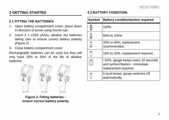
2 GETTING STARTED
2.1 FITTING THE BATTERIES1. Open battery compartment cover; press down
in direction of arrow using thumb nail.2. Insert 2 x LR03 (AAA), alkaline dry batteries
taking care to ensure correct battery polarity(Figure 2).
3. Close battery compartment cover.Rechargeable batteries can be used but they willonly have 25% to 30% of the life of alkalinebatteries.
Figure 2. Fitting batteries -ensure correct battery polarity
2.2 BATTERY CON
Symbol Battery
100%
66% to 1
33% to 6recomm
16% to 3
<16%, gand symreplacem5 loud bautomat

betion and pulle gauge. Thelock and the
ntil theTakings theobe byg ringse, or
Op_456_3_English.book Page 8 Thursday, January 22, 2009 8:05 PM
R
8
2.3 FITTING PROBES(separate versions only)
To ensure correct transfer of data from theprobe and detection of the new probe, thegauge must be switched off when
separate probes are fitted.A probe must be calibrated once it has beenfitted - see “Calibration adjustment” on page 23.
To fit the probeAlign connector keyway andpush in direction shown. Theconnector locks automatically.Note: The design of the probeconnector allows somemovement between the probeand the gauge. This is intentionaland does not affectmeasurement performance.
To release the proGrasp knurled secgently away from thconnection will unprobe will release.
To fit the PINIP™Twist the PINIP™ uconnector locates. care not to crosthreads, lock the prturning the lockin1½ times clockwiuntil tight.

R
9
E GAUGE ON
hing the gauge on for the first a language” on page 11.
te :to
al
toor a
R
R
CAL DATA STATS MENU
09 : 30 09 / 10 / 2000F1
F456
Op_456_3_English.book Page 9 Thursday, January 22, 2009 8:05 PM
2.4 THE CONTROLSThe gauge is operated by 5 keys (Figure 3).
• On/Off key : Switches the gauge on or off.• Softkeys: The function of these keys varies
and is described by symbols and writing on thebottom line of the screen.
• LED: Red/green flashes when the gauge isswitched on, green flashes when a reading istaken. Indicates when readings pass or fail the90/10 rule (see page 32). Also indicates whena reading is inside or outside limits (seepage 39).
Figure 3. Elcometer 4563 control keys
2.5 SWITCHING TH
Note: Before switctime read “Selecting
Softkeys
On/Off key
LED
Gauges with separaand PINIP™ probesPress key switch on gauge.
Gauges with integrprobes:Press key switch on gauge, place the probe onsurface.
is switched on a welcomemay be displayed briefly (Figure
al Elcometer 4563 welcome screen
e measurement values andlayed is called the Readingcter size of the measurement additional information is shownure 5). To maximise charactertatistics (see Stats on LCD,k the softkeys (see SOFTKEYS).
al Elcometer 4563 reading screens
Op_456_3_English.book Page 10 Thursday, January 22, 2009 8:05 PM
R
10
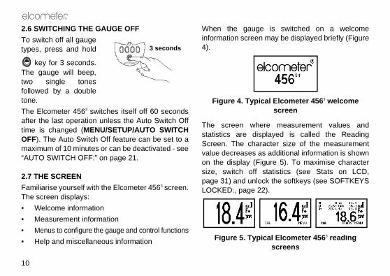
2.6 SWITCHING THE GAUGE OFFTo switch off all gaugetypes, press and hold
key for 3 seconds.The gauge will beep,two single tonesfollowed by a doubletone.The Elcometer 4563 switches itself off 60 secondsafter the last operation unless the Auto Switch Offtime is changed (MENU/SETUP/AUTO SWITCHOFF). The Auto Switch Off feature can be set to amaximum of 10 minutes or can be deactivated - see“AUTO SWITCH OFF:” on page 21.
2.7 THE SCREENFamiliarise yourself with the Elcometer 4563 screen.The screen displays:• Welcome information• Measurement information• Menus to configure the gauge and control functions• Help and miscellaneous information
When the gauge information screen 4).
Figure 4. Typic
The screen wherstatistics are dispScreen. The charavalue decreases ason the display (Figsize, switch off spage 31) and unlocLOCKED:, page 22
Figure 5. Typic
R
3 seconds

R
11
ff. left hand softkey.o switch on gauge.ill show language selectionrrent language highlighted by
nd softkey.ructions given above to select
t MENU/SETUP/LANGUAGESU - Extended menu on” on
Op_456_3_English.book Page 11 Thursday, January 22, 2009 8:05 PM
2.8 SELECTING A LANGUAGEThe Elcometer 4563 has over 20 built-in languages.When the gauge is switched on for the first timeafter dispatch from the Elcometer factory thedisplay will show the language selection screen(Figure 6).
Figure 6. Language selection screen
AT FIRST SWITCH ON1. Press Up/Down softkeys to locate language
required.2. Press SEL softkey to activate the selected
language.The screen displays an Elcometer 4563
welcome screen (Figure 4) followed by thereading screen (Figure 5).The gauge operates in the new language untilchanged.
AT ANY TIME1. Switch gauge o2. Press and hold3. Press key t
The display wscreen with cucursor.
4. Release left haFollow the instthe language.
Alternatively, selec- see “Main MENpage 18.

DING
STARThe correct type of probe?n page 42.librated?n adjustment” on page 23.statistics? on page 30. save readings in memory? on page 34.measurement do you want to
n page 21.
Op_456_3_English.book Page 12 Thursday, January 22, 2009 8:05 PM
R
12
2.9 INTERFACESYour gauge is fitted with a Bluetooth® interfacewhich makes the creation of personalised‘welcome’ screens and transfer of information toand from a PC quick and easy - see “Transferringreadings to a computer” on page 40.If you do not have a Bluetooth® interface on yourPC, you can still connect your gauge to your PC byusing the optional PC connection cable (see 15.10,page 51) and the RS232 5-pin connector on theside of the gauge.
Figure 7. RS232 interface
3 TAKING A REA
3.1 BEFORE YOU • Are you using t
See “Probes” o• Is the probe ca
See “Calibratio• Do you require
See “Statistics”• Do you want to
See “Batching”• What units of
use?See “UNITS:” o
RS232 5-pin connector

R
13
SCREEN AND MENUS
EENe reading screen (Figure 10, upon the type of measurementw the gauge is set up.
ple of reading screen with calibration method selected
lected calibration adjustment
the main MENU of the gauges to user-selectable features -
ing
)Battery state
Substrate
Unitstions/symbols
Calibration Method
Op_456_3_English.book Page 13 Thursday, January 22, 2009 8:05 PM
3.2 PROCEDURE1. Press key to switch on gauge.2. Place probe on surface to be measured. The
reading may be inaccurate if the probe isnot held as shown in Figure 8.
Figure 8. Taking a reading
3. Reading is displayed on screen (Figure 9).
Figure 9. Typical reading
4 THE READING
4.1 READING SCRThe content of thFigure 11) dependsbeing made and ho
Figure 10. Examsmooth surface
CAL: Operates semethod.MENU: This opensand provides accessee page 18.
R
Separate probe Integral probe
R
CAL DATA STATS MENU
09 : 30 09 / 10 / 2000F1
F456Automatic-switchprobe symbol(FNF probes only
Softkey func

n and measurement functionsing menus (Figure 12). Theus is shown on page 18.
ical Elcometer 4563 menu
w the status of a feature to be off or select or deselect, etc. Aes this type of feature. A ticktem indicates the function isd.ts the option displayed and in the status of a tick box off/on.
move the cursor to the. The menus scroll up/down andreen indicates the start and end
Menu title
Menu contents
Softkey functions
Op_456_3_English.book Page 14 Thursday, January 22, 2009 8:05 PM
R
14
Note: If CAL softkey symbol is flashing the gaugeshould be recalibrated. This is due to the calibrationadjustment method having been changed or aprobe change - see “Calibration adjustment” onpage 23. Batches cannot be created while the CALsoftkey symbol is flashing.
Figure 11. Reading screen in extended mode and showing full set of statistical values.
If is shown flashing in the top right corner ofyour display, it indicates that your gauge and yourPC have established a Bluetooth® connection.When your gauge and PC are connected byBluetooth®, you can transfer readings and batchesusing ElcoMaster software - see “Transferringreadings to a computer” on page 40.
4.2 MAIN MENUGauge configuratioare controlled usstructure of the men
Figure 12. Typ
Some screens allochanged e.g. on totick box indicatagainst a menu iactivated or selecteSEL softkey selecsome cases togglesUp/Down softkeysmenu item requireda line across the scof the menu.

R
15
XTENDED MENU OFF
menu - extended menu off
on and off. Toggle tick box to With BACKLIGHT activatedminated for approximately 5
ading is taken or a key pressed.fe is reduced by about one thirdis activated.
CKEDdvertent calibration adjustment.o activate/deactivate. If CALwhile CALIBRATION LOCKEDauge displays CALIBRATIONU TO UNLOCK. The messageeconds.
Op_456_3_English.book Page 15 Thursday, January 22, 2009 8:05 PM
BACK softkey returns the gauge to a previousscreen. Holding this softkey down will rapidly exitfrom any menu and return to the reading screen.
SIMPLE AND EXTENDED MENUSThe Elcometer 4563 Standard Gauge has two menustructures:• Extended menu off (simple menu mode):
The gauge is shipped from the Elcometerfactory with EXTENDED MENU turned off. Inthis simple menu mode the gauge can becalibrated and used to take measurements.This is the ideal setting for users who do notrequire access to advanced features of thegauge.
• Extended menu on (extended menu mode):Additional items are automatically added to theMENU and the STATS softkey and DATAsoftkey are activated. These give access tomore advanced functions such as statistics,batching, calibration method, print/output,setup, etc.
4.3 MAIN MENU - E
Figure 13. Main
BACKLIGHTSwitches backlightactivate/deactivate.the display is illuseconds when a reNote: The battery liwhen the backlight
CALIBRATION LOProtects against inaToggle tick box tsoftkey is pressed is activated the gLOCKED USE MENdisappears after 3 s

libration or Gauge resets. Then (Figure 15) allows one of threeselected:eturns gauge to calibrationt time of manufacture of the
will not necessarily restorevalues. The calibration of thedjusted before use, or at least that it has been previously
or the conditions of use.
sets gauge to International. DD/MM/YY date format and
ngs can also be activated at switchld softkey 3 and switch on gauge.
Op_456_3_English.book Page 16 Thursday, January 22, 2009 8:05 PM
R
16
EXTENDED MENUProvides access to additional features. Toggle tickbox to activate/deactivate. See “Main MENU -Extended menu on” on page 18.
ABOUTProvides information on Gauge, Probe, Contactinformation and Help (Figure 14):GAUGE INFORMATION: Elcometer 4563 model,software versions, etc.PROBE INFORMATION: Probe type, range, etc.CONTACT: Details of Elcometer offices worldwideand, if programmed, the contact details for theSupplier or Local Distributor.HELP: Explains symbols used on Elcometer 4563
display screens.
Figure 14. About menu
RESETSelects Factory CaRESET menu optiogauge resets to be FACTORY CAL: Rsettings created aprobe.Factory calibrationprecise calibration gauge should be achecked to ensureadjusted correctly f
INTL GAUGEb: Redefault settings e.gmetric units.
b. International settion. Press and ho
R
17
Op_456_3_English.book Page 17 Thursday, January 22, 2009 8:05 PM
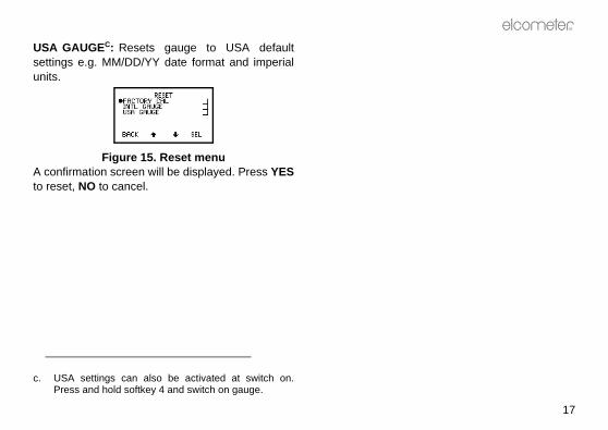
USA GAUGEC: Resets gauge to USA defaultsettings e.g. MM/DD/YY date format and imperialunits.
Figure 15. Reset menuA confirmation screen will be displayed. Press YESto reset, NO to cancel.
c. USA settings can also be activated at switch on.Press and hold softkey 4 and switch on gauge.

Op_456_3_English.book Page 18 Thursday, January 22, 2009 8:05 PM
R
18
4.4 MAIN MENU - EXTENDED MENU ONTo toggle EXTENDED MENU on/off select MENU/EXTENDED MENU/SEL

R
19
either in immediate mode or in
E YOU SURE? (Figure 17).
e last reading confirmation screen
to include reading in statisticalftkey to delete reading.g to delete the gauge displays
OT AVAILABLE (Figure 18).
e last reading not available screen
to Delete menu.
Op_456_3_English.book Page 19 Thursday, January 22, 2009 8:05 PM
The following features are added to the MENUwhen EXTENDED MENU is active:
PRINT/OUTPUTOutputs data to a printer or a PC. The batch ofreadings or the current statistical summary can beoutput via BlueTooth® or the RS232 interface.To use this function, first setup using:MENU/SETUP/OUTPUT - see “OUTPUT:” onpage 21.If no printers have been setup, PRINT/OUTPUT willdisplay a NOT AVAILABLE message.
DELETEDeletes last reading only or single batch of readings(Figure 16).
Figure 16. DELETE screen
LAST READING
Deletes last readingbatch mode.Gauge displays AR
Figure 17. Delet
Press NO softkey summary or YES soIf there is no readinLAST READING N
Figure 18. Delet
Press OK to return
SINGLE BATCH

switches STATS softkey on/off.DATA softkey and selectsG menu (Figure 20).
. DATA menu screen
ED allows DATA softkey to beTENDED MENU is active.
G screen (Figure 21) allowsed or deleted.
LETED READING screen
appear in the batch (with a tag-), but they are not included inns. are permanently deleted.
Op_456_3_English.book Page 20 Thursday, January 22, 2009 8:05 PM
R
20
Deletes the batch data.Gauge displays ARE YOU SURE? Press NOsoftkey to leave data unchanged or YES softkey todelete the batch. If there is no data stored in thememory the gauge displays NOT AVAILABLEDATA MEMORY EMPTY (Figure 19).
Figure 19. Memory empty screen
CAL METHODAllows selection of calibration method from list ofoptions - see “Calibration method” on page 23 formore details.
SETUPUsed to select, change or activate gauge features:STATISTICS: Activates statistics feature.Display - see “Display” on page 34.Set NDFT - see “Set NDFT” on page 32Select stats - see “Select stats” on page 32.
Softkey enabled - DATA: Activates DELETED READIN
Figure 20
SOFTKEY ENABLturned off when EXDELETED READINreadings to be tagg
Figure 21. DE
TAG - readings stilldeleted symbol statistical calculatioDELETE - readings

R
21
Bluetooth® PC Reply option,2) and activates data output via “Interfaces” on page 12.
2. OUTPUT screen
EPLY When the box is ticked,® connection is establishedge and a PC, the gauge will the PC after each reading is
erring readings to a computer”er information.be set at values from 1200 tovalue is 9600 baud.GE Toggle tick box to
When activated, readings areinterface as they are taken. Allters are output as bit-maps. Thisthe Elcometer Miniprinter (seee 51).
Op_456_3_English.book Page 21 Thursday, January 22, 2009 8:05 PM
PROBE: Only for dual function probes (FNF and F12). Changes probe mode.FNF probes - select from Automatic, F or N.F1 2 probes - select from F1 or F2.UNITS: Units are automatically set by the probetype, however the user can manually override theautomatic setting. Select from µm, mm, mil, thou orinch.AUTO SWITCH OFF: Changes delay beforegauge switches off when displaying ReadingScreen.• Minimum = 1 minute• Maximum = 10 minutes• Default = 1 minuteAuto switch off may be disabled by selecting ‘off’ (Inthis case, switch off using On/Off key .)
OUTPUT: Selects baud rate (Figure 2the interfaces - see
Figure 2
BLUETOOTH PC Rand a Bluetoothbetween your gauexpect a reply fromtaken. See “Transfon page 40 for furthBAUD RATE can 19200. The default RS232 BIT IMAactivate/deactivate.sent to the RS232 images and characallows printing on “Miniprinter” on pag

hen ticked, displays all menusouble height, single width fonts
lity, if needed).
. Large fonts enabled
ED: When ticked, the softkeys be displayed.
ftkeys locked/unlocked
e softkey functions disappearreen 5 seconds after the readingdisplayed, or 5 seconds after To view the functions again,e four softkeys.re always visible in menus.
Op_456_3_English.book Page 22 Thursday, January 22, 2009 8:05 PM
R
22
RS232 PLAIN TEXT Toggle tick box toactivate/deactivate. When activated, readings aresent to the RS232 interface as they are taken. Thegauge sends standard ASCII characters from theCourier New font setd. This allows printing ondevices other than the Elcometer Miniprinter, e.g.RS 232 printers or PC via Elcometer software(page 40) or via HyperTerminal.BEEP VOLUME: Changes volume.• 0 = off• 5 = loudest• Default = 3LANGUAGES: Allows selection of language.
LARGE FONTS: Wand screens using d(for improved legibi
Figure 23
SOFTKEYS LOCKfunctions will alway
Figure 24. So
When un-ticked, thfrom the reading scscreen has been pressing any key.press any one of thSoftkey functions a
d. When RS232 Plain Text is selected the following lan-guages will be output as English: Chinese, Greek,Hebrew, Japanese, Korean, Russian, Lithuanian,Farsi.

R
23
indicated on the screen by a
CAL METHOD screen
surface calibration where the on the uncoated surface and a
bove the expected thickness of
n on a thin value and a thickf the expected thickness. Thisuracy of the gauge over thefined by the two values.tion method similar to 2-Point.accuracy of the gauge over thefined by the two values.is method uses the 2-Pointual substrate materials such astypes of stainless steel, highl aluminium alloys, etc.
Op_456_3_English.book Page 23 Thursday, January 22, 2009 8:05 PM
OPENING SCREEN: Disables the opening(welcome) screens so that the gauge switches on todisplay the reading screen.If a personalised welcome screen has beendownloaded into the gauge (see page 45), OpeningScreen must be activated to display this screen.
5 CALIBRATION ADJUSTMENT
Calibration adjustment is the process of setting thegauge to known values of thickness to ensureaccuracy on different substrate types, shapes andsurface finishes.Note: When using an FNF probe it must becalibrated in both the ferrous mode and in the non-ferrous mode to ensure accuracy of reading.
5.1 CALIBRATION METHODThe calibration of the gauge can be adjusted(MENU/CAL METHOD) using several differentmethods described in National and InternationalStandards.The calibration adjustment method chosen isdependant on the condition of the substrate to be
measured and is symbol (Figure 25):
Figure 25.
SMOOTH: Smoothgauge is set to zeroknown thickness athe coating.2POINT: Calibratiovalue either side oenhances the accthickness range deROUGH: A calibraThis enhances the thickness range deSPECIAL SUB: Thcalibration for unuscast iron, certain carbon steel, specia

This uses the Zero Offset with counted average dataadings.
2004) This uses the 2-Pointwith counted average set to 3
41 60) This uses the 2-Pointwith counted average set to 5
3894) This uses the Zeroethod with a correction value offile peak-to-valley height and ata collection set to 5 readings.
ibration method is changed, e.g.ough, the gauge will display a).
alibration required screen
Op_456_3_English.book Page 24 Thursday, January 22, 2009 8:05 PM
R
24
ZERO OFFSET: This is the method described inISO 19840 for coatings on steel surfacesroughened by blast cleaning. The calibration usesthe smooth surface technique, and a correctionvalue (zero offset) is applied to each reading toaccount for the effect of the roughened surface; thevalue depends on the surface profile - see Table 1.SET OFFSET: This screen sets and changes theoffset for different surface roughness This value isused only with the Zero Offset calibration method.
5.2 PRESET CALIBRATION METHODSThe gauge also contains four preset calibrationmethods which follow relevant standards. Theseset the calibration method and the data collectionmethod (data collection method is only set when inbatching mode).
ISO: (ISO 19840) calibration methodcollection set to 5 reSSPC: (SSPC-PA2calibration method readings.SWEDISH: (SS 18calibration method readings.AUSTRALIAN: (ASOffset calibration m1/3 the surface procounted average daNote: When the calfrom Smooth to Rmessage (Figure 26
Figure 26. Rec
Table 1: Correction values from ISO 19840
Profile according to ISO 8503-1
Correction Value(µm) (Zero Offset)
Fine 10Medium 25Coarse 40

R
25
are must be taken to keep the from dust and to avoid damagelarly the thinner foils. Always
ts storage wallet before use.a High Temperature PINIP™ial thickness standards supplied “Calibrating High Temperature page 30. 5 mm (200 mils) and 13 mmauges it will be necessary tore 27). Care must be taken to
placing the foil labels between
g foils to increase thickness
Serial no.Inspected bymicron mils/thou502 19.75
TK1009
Seria
l no.
Insp
ecte
d by
micr
onm
ils/th
ou17
6.1
6.93
TK10
10
Op_456_3_English.book Page 25 Thursday, January 22, 2009 8:05 PM
If the NO softkey is pressed the CAL softkeysymbol on the Readings Screen will flash to warnthat calibration adjustment is still required. Whilethe CAL softkey symbol is flashing a new batchcannot be opened.If the YES softkey is pressed the calibrationadjustment procedure is activated - see “Calibrationadjustment procedure” on page 26.
5.3 CALIBRATION FOILS AND STANDARDSCalibration adjustment should be carried out withthe appropriate probe on the same type of metal,the same curvature and similar finish to the item tobe measured. It is best to use an uncoated sampleof the items to be tested.Calibration can be carried out using measured foilsor coated standards.FOILS (SHIMS): These are coating thicknessstandards which have been measured usingtechniques independent of the gauge. They areideal for calibration because they provide a knownvalue of thickness on the actual substrate to bemeasured. Calibration certificates for foils areavailable upon request.
When using foils cfoils clean and freeby creasing particuremove a foil from iWhen calibrating Probe use the specwith the probe - seePINIP™ Probes” onNote: To calibrate(500 mils) range gstack the foils (Figuavoid errors due tothe foils.
Figure 27. Stackin

l depends on the calibrationt the calibration is in two steps.ple is for a Smooth Calibration
air and press CAL softkey
1 - on thickness standard
turns the gauge to the Readinge Calibration Procedure withoutnges.llows the user to take readingsuracy of the current calibration.s do not affect statistical
nd are not added to batch
on calibration standard. Theay a reading.
Op_456_3_English.book Page 26 Thursday, January 22, 2009 8:05 PM
R
26
COATED STANDARDS: Thickness standards usingtypical substrate materials coated with hardwearingmaterials and measured using techniquesindependent of the gauge.Coated standards are most often used to confirmthat the gauge meets its specifications if it is notpossible to use foils (shims).
5.4 CALIBRATION ADJUSTMENT PROCEDURECalibration adjustment can be carried out at anytime by pressing CAL softkey from the readingscreen. To prevent inadvertent calibrationadjustment the CAL softkey can be locked(MENU/CALIBRATION LOCKED).The user is guided through the operation of thechosen calibration procedure by means ofinstructions and illustrations on the graphicsscreen. Audible warnings are also provided whenaction is required, e.g. when the probe must beplaced down to get a reading.If the routine is interrupted in any way the previoussettings will be restored until after the full calibrationroutine has been completed or the reset has beencompleted.
The screen detaimethod chosen, buThe following examadjustment.
Step 11. Hold probe in
(Figure 28).
Figure 28. Step
ESC softkey reScreen from thmaking any chaTEST softkey ato verify the accThese readingcalculations amemory.
2. Place probe gauge will displ

R
27
icates over-range (Figure 30).ing within range clears this
. Over-range reading
n uncoated standard or zerouge will take and display a
then replace on uncoatedro plate. Gauge displays the
f these readings and the last
Op_456_3_English.book Page 27 Thursday, January 22, 2009 8:05 PM
3. Lift probe and then replace on calibrationstandard. Gauge displays the average ( ) ofthese readings and the last reading. Repeatthis action until a stable reading is obtained.
Figure 29. Step 1 - Calibration adjustment on thickness standard
To reject the displayed reading and start thecalibration procedure again, press both the Upand Down softkeys at the same time.To adjust the displayed reading until it iscorrect relative to the thickness standard usethe Up/Down softkeys.
4. Press SET softkey to accept the value.
Note: - - - indTaking a readscreen.
Figure 30
Step 21. Place probe o
plate. The gareading.
2. Lift probe andstandard or zeaverage ( ) o
First reading Second reading
Average
Last

l display the option to test thee gauge.
EST READINGS screen
NO softkey to complete thestment procedure and return
e reading screen, or proceed tongs - see Taking test readings
Op_456_3_English.book Page 28 Thursday, January 22, 2009 8:05 PM
R
28
reading. Repeat this action until a stablereading is obtained.
Figure 31. Step 2 - Calibration adjustment on uncoated sample
To reject the displayed reading and start Step2 of the calibration procedure again, press theReset softkey .
3. Press ZERO softkey to zero the display (Figure32).
Figure 32. Zero the display
4. Press SET softkey to accept this value.
The gauge wilcalibration of th
Figure 33. T
5. Either press calibration adjuthe gauge to thtake test readibelow.
First reading Second reading
R
29
ken on a thin standard valuecoated base.
tep 2 - On thin standard
ing will display the average. Thisl for rough surfaces as it allowsrface to be accounted for in theent, therefore improving thege.
- Calibration adjustment on hin standard
g Second reading
Op_456_3_English.book Page 29 Thursday, January 22, 2009 8:05 PM
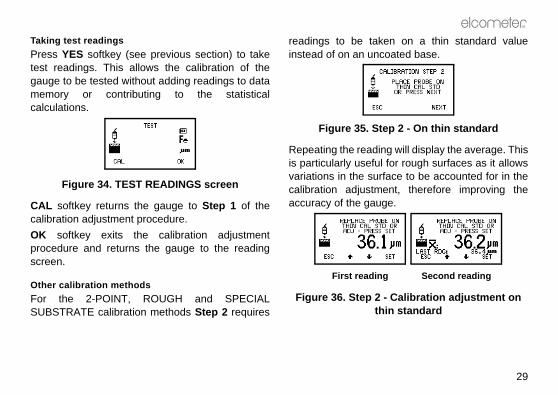
Taking test readingsPress YES softkey (see previous section) to taketest readings. This allows the calibration of thegauge to be tested without adding readings to datamemory or contributing to the statisticalcalculations.
Figure 34. TEST READINGS screen
CAL softkey returns the gauge to Step 1 of thecalibration adjustment procedure.OK softkey exits the calibration adjustmentprocedure and returns the gauge to the readingscreen.
Other calibration methodsFor the 2-POINT, ROUGH and SPECIALSUBSTRATE calibration methods Step 2 requires
readings to be tainstead of on an un
Figure 35. S
Repeating the readis particularly usefuvariations in the sucalibration adjustmaccuracy of the gau
Figure 36. Step 2t
First readin

63 Standard has a Statisticshich calculates and displays aof readings as they are taken.ulations are also applied to thehin a single batch in memory. MENU is active, press STATSTATS MENU (Figure 37).
e 37. Stats menu
ble are:dings
tion ariation g g equal to NDFT
Op_456_3_English.book Page 30 Thursday, January 22, 2009 8:05 PM
R
30
Calibrating High Temperature PINIP™ ProbesSpecial thickness standards are supplied withF1 2 High Temperature PINIP™ Probes - seepage 44. These thickness standards should beused in place of the calibration standard in Step 1of “Calibration adjustment procedure” on page 26.1. Place appropriate thickness standard over end
of PINIP™ probe.2. Press CAL softkey.
3. Place probe on hote surface and take areading.
4. Lift probe and then replace on hot surface totake second reading.
5. Repeat as necessary until reading is stable.6. Press SET to accept value.7. Remove thickness standard from end of
PINIP™ probe.8. Proceed with Step 2 - see page 27.
6 STATISTICS
The Elcometer 45feature (STATS) wstatistical analysis The statistical calcreadings stored witWhen EXTENDEDsoftkey to access S
Figur
The statistics availa• Number of Rea• Mean • Standard Devia• Coefficient of V• Highest Readin• Lowest Readin• % greater to or
e. The temperature of the surface used for calibrationshould be equal to the temperature of the substratebeing measured.

R
31
ntation of the chosen statisticalng screen.
ng screen with all statistics
l statistical values selected inPLAY.
Combined statistics symbol
Op_456_3_English.book Page 31 Thursday, January 22, 2009 8:05 PM
• % between 90% and 100% of NDFT • 90/10 pass or fail For more information see:• “Select stats” on page 32.• “Statistics terminology” on page 47.
6.1 ENLARGE STATSDisplays the chosen statistical values as double-height characters. The example screens (Figure38) appear when all the statistical values areselected. The Up/Down softkeys can be used tomove through the list. OK softkey returns to theReading Screen.
Figure 38. Enlarged statistics
6.2 STATS ON LCDActivates the presevalues on the readi
Figure 39. Readi
6.3 CLEAR STATSResets to zero alSTATS MENU/DIS

t valuef for NDFTg is 320 µm
t this value, select ‘SET NDFT’,oftkeys to adjust the valueK. If any readings have beente mode, a screen will behat the statistics will be cleared.ue (to change the NDFT value)
nd leave the value unchanged).
ADINGSble of displaying PSPC readings/10 rule as defined in the IMOi
ule (Figure 41):of all thickness measurements than or equal to NDFT, and
PSPC for Ballast Water Tanks Thicknessdard for Protective Coatings
time Organisation
Op_456_3_English.book Page 32 Thursday, January 22, 2009 8:05 PM
R
32
6.4 SELECT STATSAllows the user to chose which statistical values aredisplayed. The default condition is all values exceptPSPC readings (Figure 40).
Figure 40. Select stats menu
Use Up/Down softkeys to move cursor and SELsoftkey to select or deselect the statistical values.Note: When PSPC readings is selected, no othervalues can be selected and the SET NDFT screenwill be displayed automatically.See “Set NDFT” on page 32 for further informationabout PSPC and NDFT.
6.5 SET NDFTThe factory defaul(12.6 mils).If you need to adjususe the Up/Down sand then press Otaken in immediadisplayed warning tPress YES to continor NO to escape (a
ABOUT PSPCH REYour gauge is capaaccording to the 90requirements.To pass the 90/10 r• At least 90%
shall be greater
f. Default value fromg. Nominal Dry Filmh. Performance Stani. International Mari

R
33
tics are selected the standard on the screen are replaced byure 42):
C statistics - selected and d on reading screeng readings with PSPC statisticse will beep and flash the LED:
: 1 beep Green flash: 3 beeps Green flash
: 3 beeps Red flashule is not compatible with thedata collection method (seet be used when saving readingsIf PSPC readings are selectederage batch mode, or a countedened while PSPC readings arearning screen will be displayed.sferring PSPC readings data toe 42 for additional information.
Op_456_3_English.book Page 33 Thursday, January 22, 2009 8:05 PM
• none of the remaining measurements shall bebelow 0.9 x NDFT.
Figure 41. Pass/Fail criteria for 90/10 rule
When PSPC statisstatistics displayedthose for PSPC (Fig
Figure 42. PSPdisplaye
While you are takinselected, your gaugPassFail (90%)Fail (<0.9xNDFT)Note: The 90/10 rcounted average page 36) and cannousing this method. while in counted avaverage batch is opbeing displayed a wNote: Refer to “TranElcoMaster” on pag
SUBSTRATE
NDFT
0.9 x
COATING
NDFT
At least 90% ofall readingsmust be in thiszone...
... no readingsmust be in thiszone
To PASS 90/10
AND
90/10 FAILED ifLess than 90%of all readingsare in thiszone...
OR
... any readingsare in this zone

3 operates in one of two modes;.he gauge takes readings and but does not store any readings43).
g screen - Immediate mode
gauge takes readings and and stores readings in memoryuge stores readings in a singleeadings.
Op_456_3_English.book Page 34 Thursday, January 22, 2009 8:05 PM
R
34
6.6 DISPLAYOnly applies when using dual function probes.Allows selection of the types of readings used in thestatistical calculation when a dual function probe isconnected.Probe OptionsFNF F, N or F and N combinedj
F1 2 F1, F2 or F1 and F2 combinedj
7 BATCHING
The Elcometer 456immediate or batchIMMEDIATE MODE: Tcalculates statisticsin memory (Figure
Figure 43. Readin
BATCH MODE: The calculates statistics(Figure 44). The gabatch of up to 250 r
j. When readings are combined a symbol will bedisplayed on the Reading Screen (Figure 39).

R
35
G the gauge to immediate modeings are stored in memory. Thee Reading Screen.
TCHcreates) the single batch #1.L softkey symbol is flashing, ae opened. Calibrate the gaugew batch. FNF probes should be
e and in N mode.lready contains readings, OPENot available and the gauge will The existing batch must bebefore a new batch can be
is opened the following settingsbatch from immediate mode:hodd)stmentethod and offset must be set
the new batch. Calibration
Op_456_3_English.book Page 35 Thursday, January 22, 2009 8:05 PM
Batch mode (batching) allows reading data to becollected in a single group to allow easier analysisof large structures or complex assemblies.
Figure 44. Reading screen - Batch mode
The Elcometer 4563 Standard has memory capacityfor up to 250 readings in a single batch.Batching is configured using the DATA MENU.To access the DATA MENU (Figure 45) press theDATA softkey (this softkey is only displayed withEXTENDED MENU on).
Figure 45. DATA MENU screen
7.1 EXIT BATCHINThis option returnsand no further readgauge returns to th
7.2 OPEN NEW BAThis option opens (Note: While the CAnew batch cannot bbefore opening a necalibrated in F modNote: If the batch aNEW BATCH is nbeep three times.deleted (page 19) opened (created).When a new batch are copied into the • Calibration met• Offset (if applie• Calibration adjuNote: Calibration mbefore opening

NEW BATCH screen (Figurent batch settings.
OPEN NEW BATCH screen - mediate mode
Limits for the batch can beme once the batch has beenimits” on page 39.ethod must be set before OK
hodn Method can be changed byollection Method softkey or
Lower and upper limits
Number of readings in batch (0)
Calibration method
Offset
Calibration type
Op_456_3_English.book Page 36 Thursday, January 22, 2009 8:05 PM
R
36
adjustment can be changed after the batch hasbeen created - see “Calibration adjustmentprocedure” on page 26.The initial OPEN NEW BATCH screen (Figure 46)stays on while the gauge sets up the batch, asindicated by the progress bar.
Figure 46. Initial OPEN NEW BATCH screen - Immediate mode
ESC takes the gauge back to DATA MENU.
The second OPEN47) shows the curre
Figure 47. SecondIm
Upper and lower changed at any ticreated - see “Set lData collection msoftkey is pressed.
Data Collection MetThe Data Collectiopressing the Data C
Batch number
Data collection method
Data collection method softkey
Limits selected/deselected symbol
R
37
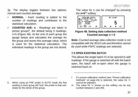
can be changedl by pressingy.
ng data collection methodted average n = 5
rage data collection mode is not 90/10 rule and therefore cannotC readings are selected.
G BATCHle batch #1 to be opened to addge is switched off with the batchill re-open when the gauge is
tion method (see “Preset calibratione 24) is selected, the value for ‘n’d. shown on the softkey can be any2 and 255.
Op_456_3_English.book Page 37 Thursday, January 22, 2009 8:05 PM
. The display toggles between two options,normal and counted average:• NORMAL - Each reading is added to the
number of readings and contributes to thestatistical calculation.
• COUNTED AVE: n - Readings are taken inpreset groupsk, the default being 5 readings,n=5 (Figure 48). At the end of each group thegauge beeps and calculates the average forthe group and stores this average value, whichis used for the statistical calculation. Theindividual readings in the group are not stored.
The value for nthe n=5m softke
Figure 48. SettiCoun
Note: Counted avecompatible with thebe used while PSP
7.3 OPEN EXISTINThis allows the singreadings. If the gauopen, the batch wswitched back on.
k. When using an FNF probe in AUTO mode the firstreading in each group will ‘lock’ the probe to that sub-strate for the whole of the group.
l. If a preset calibramethods” on pagcannot be adjuste
m. The value for ‘n’number between
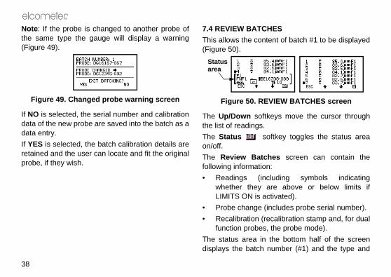
HEStent of batch #1 to be displayed
VIEW BATCHES screen
keys move the cursor through
oftkey toggles the status area
hes screen can contain then:cluding symbols indicatingare above or below limits ifctivated).includes probe serial number).ecalibration stamp and, for dual, the probe mode). the bottom half of the screennumber (#1) and the type and
Op_456_3_English.book Page 38 Thursday, January 22, 2009 8:05 PM
R
38
Note: If the probe is changed to another probe ofthe same type the gauge will display a warning(Figure 49).
Figure 49. Changed probe warning screen
If NO is selected, the serial number and calibrationdata of the new probe are saved into the batch as adata entry.If YES is selected, the batch calibration details areretained and the user can locate and fit the originalprobe, if they wish.
7.4 REVIEW BATCThis allows the con(Figure 50).
Figure 50. RE
The Up/Down softthe list of readings.The Status son/off.The Review Batcfollowing informatio• Readings (in
whether they LIMITS ON is a
• Probe change (• Recalibration (r
function probesThe status area indisplays the batch
Status area

R
39
with Up/Down softkeys. When displayed, press OK to enter.tivated the out-of-limits reading a triple beep and a red light onreading within limits is indicatednd a green light. Out-of-limits
ill be stored in the batch and canatch is reviewed.
Ys the amount of free memorye of readings (Figure 53).
REE MEMORY screen
Op_456_3_English.book Page 39 Thursday, January 22, 2009 8:05 PM
serial number of the probe used when the batchwas created.
7.5 SET LIMITSUpper and lower values can be set by the user tomonitor specification values.To activate limits tick the LIMITS ON box (Figure51).
Figure 51. SET LIMITS screen
To set the UPPER and LOWER limit values movethe cursor to the limit required and press SEL.The gauge will display the current settings (Figure52). Values shown are for illustration only.
Figure 52. Setting upper and lower limits
Adjust the values the correct value isWith LIMITS ON acwill be indicated bythe keypad LED. A by a single beep asymbols and wbe seen when the b
7.6 FREE MEMORThis option displayavailable for storag
Figure 53. F

create personalised welcomeload them to your gauge.ta Conversion Software. Thisrts existing measurement dataformat. The following types of
data can be converted;S Win, EDCS Plus and EDCS.n also be downloaded from thewww.elcometer.com/downloads
G USING A CABLEgauge to your PC using the
gauge and ensure the Readingyed.
are and follow the instructionse software.
G USING A BLUETOOTH®
how to interface your gauge withwnload data are included with file supplied with the software.
Op_456_3_English.book Page 40 Thursday, January 22, 2009 8:05 PM
R
40
8 TRANSFERRING READINGS TO A COMPUTER
Your gauge comes complete with software whichallows data to be transferred to a PC usingBluetooth® or the optional PC connection cable.The CD supplied with your gauge includes thefollowing software:
• Elcometer Data Transfer Software (EDTS+
Excel Link). This software allows the user totransfer data from the memory of the gaugeinto Microsoft Excel using the PC connectioncable. The data can then be processed insoftware such as Word or Excel.
• ElcoMaster Software for MeasurementData. This software allows the user to transferdata from the memory of the gauge to a PC forarchiving, analysis and reporting. Data can betransferred using the PC connection cable orBluetooth®. Data can also be transferred as themeasurements are taken. ElcoMaster includesall the charts that you may need together witha report designer to let you design your reportsthe way you wish to see them. ElcoMaster can
also be used toscreens and up
• ElcoMaster Dasoftware conveto ElcoMaster measurement Elcometer EDC
All this software caElcometer website
8.1 TRANSFERRIN1. Connect your
optional cable.2. Switch on your
Screen is displa3. Start the softw
included with th
8.2 TRANSFERRINCONNECTIONFull instructions on ElcoMaster and dothe ElcoMaster help
R
41
EASUREMENTS AS THEY
can be transferred from youra Bluetooth® connection as the
s a feature which checks that ay the gauge has arrivedr PC. If the reading does not
n error message is displayed onrther readings cannot be taken
, tick the Bluetooth® PC ReplyU>SETUP>OUTPUT - see
e 21.s ticked, and a Bluetooth®
lished between your gauge andill expect a reply from the PC
s taken.
Op_456_3_English.book Page 41 Thursday, January 22, 2009 8:05 PM
VERIFYING A BLUETOOTH® CONNECTIONWhen a Bluetooth® connection is establishedbetween your gauge and a PC, the gauge producestwo high pitch beeps and shows a flashingBluetooth® icon in the top right corner of thedisplay. When the connection is closed or lost, thegauge produces two lower pitch beeps and the iconis removed.
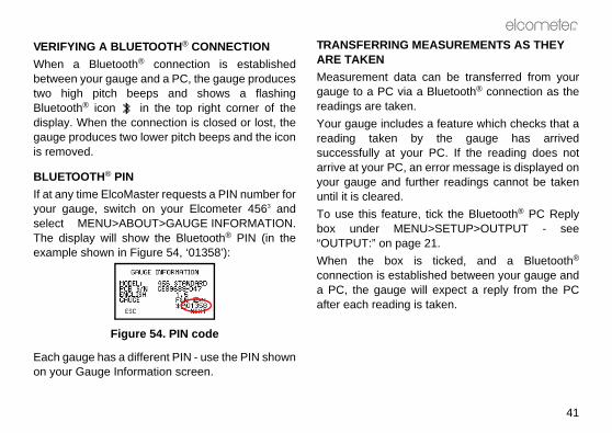
BLUETOOTH® PINIf at any time ElcoMaster requests a PIN number foryour gauge, switch on your Elcometer 4563 andselect MENU>ABOUT>GAUGE INFORMATION.The display will show the Bluetooth® PIN (in theexample shown in Figure 54, ‘01358’):
Figure 54. PIN code
Each gauge has a different PIN - use the PIN shownon your Gauge Information screen.
TRANSFERRING MARE TAKENMeasurement datagauge to a PC via readings are taken.Your gauge includereading taken bsuccessfully at youarrive at your PC, ayour gauge and fuuntil it is cleared.To use this featurebox under MEN“OUTPUT:” on pagWhen the box iconnection is estaba PC, the gauge wafter each reading i

t the NDFT value is transferredaddition to the readings data.
of probes is available for theating Thickness Gauge. Probes
non-ferrous (N) and dual (FNF) operation are availableuilt-in) or separate options.e fully interchangeable and areard, PINIP™ and miniature
lug-In Integral Probe) is an which plugs in to a separates all the benefits of an integral
ibility of a separate gauge in a
probes permit measurementsricted.
PROBES the thickness of non-magneticic substrates. They can be used
Op_456_3_English.book Page 42 Thursday, January 22, 2009 8:05 PM
R
42
If this reply is not received within half a second ofsending the reading, an error message will bedisplayed (Figure 55).
Figure 55. Bluetooth PC Reply error message
If the Bluetooth® connection is still established andthe reply is received after half a second then themessage will clear automatically, (this indicates thatthe Bluetooth® connection is operating at the limit ofits range). If the Bluetooth® connection has beenlost, then the error message will remain on thescreen until a key is pressed.
8.3 TRANSFERRING PSPC READINGS DATA TO ELCOMASTERWhen transferring PSPC readings to ElcoMaster,run ElcoMaster and then tick the ‘Use 456 GaugeNDFT’ box in File>Preferences>Batch Info>NDFTSettings.
This will ensure thafrom your gauge in
9 PROBES
An extensive rangeElcometer 4563 Cofor ferrous (F), ferrous/non-ferrousas either integral (bSeparate probes aravailable in standformats.PINIP™ format (Pintegral style probegauge. This providegauge and the flexsingle unit.Miniature separatewhere space is rest
9.1 FERROUS (F) F probes measurecoatings on magnet

R
43
CHANGEABILITY shows which probes can be
pes of Elcometer 4563 Gauge.
Gauge TypeF N FNF
****
e
igh
straight 45° 90°
Op_456_3_English.book Page 43 Thursday, January 22, 2009 8:05 PM
on paint, plastic, galvanising, enamel, powder paint,hard chrome and other coatings such as electro-less nickel applied to steel or iron.
9.2 NON-FERROUS (N) PROBESN
N probes measure the thickness of non-metalliccoatings on non-magnetic metals. They can beused on anodising, paint, plastic coatings, powderpaint, etc. applied to aluminium, brass, non-magnetic stainless steel, etc.
9.3 DUAL FERROUS/NON-FERROUS (FNF) PROBESFNF probes are dual function, F and N in one probe.FNF gauges will automatically detect the type ofsubstrate and set the mode accordingly.Alternatively the mode can be set manually - see“PROBE:” on page 21 and “Coatings on galvanisedor metallised steel” on page 44.
9.4 PROBE INTERThe following tableused in the three ty
n. Using an N probe (or an FNF probe manually set toN1) on a ferrous substrate will give a reading, but thereading will be incorrect.
Probe type
FER
RO
US
F1F2F1 2F3F1 right angleF2 right angleF1 2 right anglF1 telescopicF2 telescopicF1 PINIP™F2 PINIP™F1 2 PINIP™ HTempF3 PINIP™FM3 miniatureFM3 miniatureFM3 miniature
PERATURE PINIP™
robes are capable of measuringces up to 250°C (480°F). Wearate protective clothing and takevoid bodily contact with the hotsurement.maximum measurement speedrobes - see page 48.cial calibration procedure - seemperature PINIP™ Probes” on
GALVANISED OR EL fixed N1 mode may be used totings on galvanised, aluminiumayed steel substrates.uge to the N1 mode/PROBE).rate the gauge on a sample ofl - see “Calibration adjustment”
Op_456_3_English.book Page 44 Thursday, January 22, 2009 8:05 PM
R
44
* indicates probes available for integral typegauges.
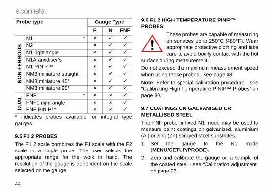
9.5 F1 2 PROBESThe F1 2 scale combines the F1 scale with the F2scale in a single probe. The user selects theappropriate range for the work in hand. Theresolution of the gauge is dependent on the scaleselected on the gauge.
9.6 F1 2 HIGH TEMPROBES
These pon surfaappropricare to a
surface during meaDo not exceed the when using these pNote: Refer to spe“Calibrating High Tepage 30.
9.7 COATINGS ONMETALLISED STEThe FNF probe in measure paint coa(Al) or zinc (Zn) spr1. Set the ga
(MENU/SETUP2. Zero and calib
the coated steeon page 23.
NO
N-F
ERR
OU
S
N1 *N2N1 right angleN1A anodiser’sN1 PINIP™NM3 miniature straightNM3 miniature 45°NM3 miniature 90°
DU
AL FNF1 *
FNF1 right angleFNF PINIP™
Probe type Gauge TypeF N FNF
R
45
D TRANSIT
ge incorporates a Liquid Crystal(LCD). If the display is heated°C (120°F) it may be damaged. happen if the gauge is left in a sunlight.uge in its carrying pouch when ies from the gauge and storee gauge is to remain unused fore. This will prevent damage to
event of malfunction of the
E
the finest hand-held coating the world. If looked after, it will
ot contain any user-serviceable unlikely event of a fault, theturned to your local Elcometerto Elcometer. The warranty will
Op_456_3_English.book Page 45 Thursday, January 22, 2009 8:05 PM
Care must be taken to ensure that thecalibration conditions are not affected bychanges in the zinc or aluminium coatingthickness. This can be determined by checkingthe zero over an area of the galvanised ormetal-coated steel. Metal coatings on steelabove 50 µm (2 mil/thou) should be consistentenough to obtain a stable zero on the layer ofmetal.
3. Take readings.
10 PERSONALISED WELCOME SCREEN
A personalised welcome screen can be created anddownloaded into the gauge.Screen dimensions are 128 pixels x 64 pixels. Thewelcome screen is typically used to personalise thegauge with a logo, serial number, user name, etc.This is the first screen displayed when the gauge isswitched on.Use your Bluetooth® interface or PC connectioncable with ElcoMaster software to create andupload the screen - see the instructions includedwith ElcoMaster.
11 STORAGE AN
This gauDisplay above 50This can
car parked in strongAlways store the gait is not being used.Remove the batterthem separately if tha long period of timthe gauge in thebatteries.
12 MAINTENANC
You own one of thickness gauges inlast a lifetime.The gauge does ncomponents. In thegauge should be resupplier or directly
Op_456_3_English.book Page 46 Thursday, January 22, 2009 8:05 PM
R
46
be invalidated if the gauge has been opened.Contact details are stored in the gauge -MENU/ABOUT/CONTACT.Worldwide: [email protected] USA/Canada: [email protected]: Probes will eventually wear. Probe life willdepend on the number of measurements takenand how abrasive the coating is. Probe life canbe prolonged by careful positioning of theprobe on the surface.Replacement separate and PINIP™ probes canbe fitted by the user without the need to returnthe gauge for service.Gauges with an integral probe have to bereturned for re-programming or replacement ifthe probe becomes worn or damaged.
R
47
divided by the mean for a group
of readings.
of readings.
the individual readings divided
number of readings taken in a Readings is the number of gs taken.e spread of values in a group of
equal to the value of NDFT (see
alue of NDFT but greater than
test, = fail due to a reading is displayed, insufficient valid - take more measurements)
Op_456_3_English.book Page 47 Thursday, January 22, 2009 8:05 PM
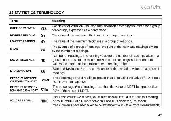
13 STATISTICS TERMINOLOGY
Term Meaning
COEF OF VARIAT’N Coefficient of Variation. The standard deviationof readings, expressed as a percentage.
HIGHEST READING The value of the maximum thickness in a group
LOWEST READING The value of the minimum thickness in a group
MEAN The average of a group of readings; the sum ofby the number of readings.
NO. OF READINGS Number of Readings. The running value for thegroup. In the case of the mode, the Number ofvalues recorded, not the total number of readin
STD DEVIATION Standard Deviation. A statistical measure of threadings.
PERCENT GREATER OR EQUAL TO NDFT
The percentage (%) of readings greater than or“Set NDFT” on page 32)
PERCENT BETWEEN 90% AND 100% NDFT
The percentage (%) of readings less than the v90% of the value of NDFT.
90:10 PASS / FAIL 90/10 test results: = pass, = failed on 90%below 0.9xNDFT (if a number between 1 and 10 measurements have been taken to be statistically

ut outer sleeve: 150°C (300°F)80°C (176°F)
LY2 x LR03 (AAA), alkalineo dryeablep equivalents.
rs continuous use with alkaline00 to 20 000 readings at an
rate Probe (FNF1), 190g z)rate Probe (PINIP™), 155g z)ral Probe, 130g (4.6oz)mm x 70 mm x 35 mm" x 2.76" x 1.38")
to 50°C (32°F to 120°F)ation outside these limits nds upon climatic conditions. impact ABS
Op_456_3_English.book Page 48 Thursday, January 22, 2009 8:05 PM
R
48
14 TECHNICAL DATA
14.1 MEASUREMENT SPEED>60 readings per minute.When measuring high temperature materialsmeasurement speed must be reduced to preventoverheating of the probe. The maximummeasurement speed of the High TemperaturePINIP™ probe at 250°C (480°F) is 4 readings perminute.
14.2 MINIMUM SUBSTRATE THICKNESSFerrous: 300 µm (12 mils)Non-ferrous: 100 µm (4 mils)Measurements can be taken on thinner substratesif 2-point calibration is carried out either side of therequired substrate thickness, however gauges willhave reduced range when adjusted for thinsubstrates.
14.3 PROBE OPERATING TEMPERATURESeparate ferrous probes: 150°C (300°F)High temperature PINIP™ probes: 250°C (480°F)
Miniature probes withoAll other probes:
14.4 PHYSICAL
14.5 POWER SUPPInternal batteries, batteries or recharg
Battery life30q hours to 40 houdry batteries. (15 0
Weight (including batteries):
Sepa(6.7oSepa(5.5oInteg
Dimensions: 130(5.12
Gauge operating temperature:
0°C Operdepe
Case: High

R
49
S3 is complete with all the itemsted and take measurements.ing accessories are optional.
e consumable items that may over the lifetime of the gauge.s are available from Elcometer,
eter supplier. At time of orderingales part number which followsach accessory.
extensive range of 456 probesfrom Elcometer, your local
r or the Elcometer website,.
Op_456_3_English.book Page 49 Thursday, January 22, 2009 8:05 PM
average of 8 readings per minute.) Battery life isreduced by one third when using the backlight.
14.6 PACKAGINGThe gauge is packed in cardboard and plasticpackaging. Please ensure that this packaging isdisposed of in an environmentally sensitivemanner. Consult your Local EnvironmentalAuthority for further guidance.
15 ACCESSORIE
The Elcometer 456required to get starMany of the followHowever, some arneed to be replacedAll these accessorieor your local Elcomplease quote the sthe description of e
15.1 PROBESFull details of the can be obtained Elcometer suppliewww.elcometer.com
o. Alkaline batteries must be disposed of carefully toavoid environmental contamination. Please consultyour local environmental authority for information ondisposal in your region.Do not dispose of any batteries in fire.
p. Rechargeable batteries can be used if they arecharged outside the gauge.
q. Battery life is reduced to approximately 25% of drybattery life when using rechargeable batteries. Followthe instructions provided by the battery manufacturerwhen charging and disposing of rechargeablebatteries.

KNESS STANDARDS IFICATE
EMENT JIGioning on small components aig is available and an adapterith the full range of miniatureable as an accessory.
TERS
4 Values): T995111261ard (4 Values): T9951112712 Values): T995166001ard (2 Values): T995166011
g: T95012880
F and N T9997766-
FNF probes): T99913225 (F & N T9997381-
Op_456_3_English.book Page 50 Thursday, January 22, 2009 8:05 PM
R
50
15.2 FOIL SETS
Individual foils in the range 12.5 µm to 20 mm (0.5mil to 790 mils) and customised sets chosen fromthis range are also available. Consult your localElcometer supplier.
15.3 CALIBRATION CERTIFICATES FOR FOILSCertificates traceable to National Standardsincluding UKAS and NIST are available on request.
15.4 TEST CERTIFICATESA certificate with results of a standard test on knownfoil values over the full range of the probe. Orderusing sales part number TEST-456.
15.5 COATED THICINCLUDING CERT
15.6 PROBE PLACTo aid probe positprobe placement jsuitable for use wprobes is also avail
15.7 PROBE ADAP
2.2 mm (85 mils) 8 pieces: T9904199F1.3 mm (51 mils) 3 pieces: T9904199G5.5 mm (220 mils) 4 pieces: T9904199J15 mm (595 mils) 4 pieces: T9904199K
Ferrous Standard (Non-Ferrous StandFerrous Standard (Non-Ferrous Stand
Probe placement ji
Jumbo Hand Grip (probes):Jumbo Hand Grip (V Adapter for pipesprobes):

R
51
DS
TION CABLE
pin adapter may be required fororts.
® MODULE
ion: T45616161robe Version: T45616162
tion Cable (9- T99916217
odule: T99920130
Op_456_3_English.book Page 51 Thursday, January 22, 2009 8:05 PM
15.8 Miniprinter42 column, rechargeable battery poweredMiniprinter complete with charger. Three chargeroptions:
Miniprinter spares
15.9 BENCH STAN
15.10 PC CONNEC
Note: A 9-pin to 25-certain PC RS232 p
15.11 BLUETOOTH
V Adapter for pipes (FNF probes): T99913133
230V (UK Plug): X4569964B230V (European Plug): X4569964C110V (US Plug): X4569964D
456 to printer connection cable (25-pin):
T45616267
Ribbon Cassettes (Pack of 5): T9769992-Paper Rolls (Box of 20): T9999993-
Integral Probe VersIntegral/Separate P
456 to PC Connecpin):
USB Bluetooth® M

WRIST HARNESS
Op_456_3_English.book Page 52 Thursday, January 22, 2009 8:05 PM
R
52
16 RELATED EQUIPMENT
Elcometer produces a wide range of coatingthickness gauges and associated paint inspectionequipment. Users of the Elcometer 4563 may alsobenefit from the following Elcometer products:• Uncured powder thickness gauges• Coatings analyser• Inspection management software• Mechanical coatings thickness gauges• Appearance testers• Adhesion testersFor further information contact Elcometer, yourlocal Elcometer supplier or visitwww.elcometer.com
17 FITTING THE
1. Pass harnessround pin
2. Pass harnessthrough loop
3. Pull tight

R
53
easured.
ion in range0 µm to 99.9 µm100 µm to 1500 µm0 mil to 4.99 mils5 mils to 60 mils0 mm to 0.99 mm1.0 mm to 5.0 mm0 mil to 49.9 mils50 mils to 200 mils0 mm to 1.99 mm2 mm to 13 mm0 mil to 99.9 mils100 mils to 500 mils0 µm to 99.9 µm100 µm to 500 µm0 mil to 3.99 mils4 mils to 10 mils0 mm to 1.99 mm2 mm to 25 mm0 mil to 99.9 mils100 mils to 980 mils0 mm to 1.99 mm2 mm to 30 mm0 mil to 99.9 mils100 mils to 1200 mils
Op_456_3_English.book Page 53 Thursday, January 22, 2009 8:05 PM
18 PROBE MEASUREMENT PERFORMANCE
Scale Total range Accuracya
a. Whichever is the greater. Lower value achieved when calibrated close to the thickness to be m
ResolutF1F1 2 (F1 mode)FNF1N1, N1A
0 µm to 1500 µm ±1% to ±3% or ±2.5 µm 0.1 µm1.0 µm
0 mil to 60 mils ±1% to ±3% or ±0.1 mil 0.01 mil0.1 mil
F1 2 (F2 mode)N2
0 mm to 5.0 mm ±1% to ±3% or ±0.02 mm 1.0 µm10 µm
0 mil to 200 mils ±1% to ±3% or ±1 mil 0.1 mil1 mil
F3 0 mm to 13 mm ±1% to ±3% or ±0.05 mm 1.0 µm10 µm
0 mil to 500 mils ±1% to ±3% or ±2.0 mils 0.1 mil1 mil
FM3NM3
0 µm to 500 µm ±1% to ±3% or ±2.5 µm 0.1 µm1.0 µm
0 mil to 10 mils ±1% to ±3% or ±1.0 mil 0.01 mil0.1 mil
F6 0 mm to 25 mm ±1% to ±3% or ±0.1 mm 10 µm100 µm
0 mil to 980 mils ±1% to ±3% or ±2.0 mils 1 mil10 mil
N6 0 mm to 30 mm ±1% to ±3% or ±0.05 mm 10 µm100 µm
0 mil to 1200 mils ±1% to ±3% or ±2.0 mils 1 mil10 mil

inimum mple ameter
Cal foil valuea
accuracy under these measurement
mm (0.16”) 250 µm (10 mil)
mm (0.32”) 1 mm (40 mil)
mm (0.55”) 2.5 mm (100mil)
mm (0.24”) 250 µm (10 mil)
mm (0.32”) 250 µm (10 mil)
mm (0.16”) 250 µm (10 mil)
Op_456_3_English.book Page 54 Thursday, January 22, 2009 8:05 PM
R
54
19 PROBE CAPABILITIES
19.1 INTEGRAL PROBES
Probe typeMinimum convex surface diameter
Minimum concave surface radius
HeadroomMsadi
a. This is the recommended maximum calibration foil value to achieve the specifiedconditions
F1 (or F1 2 set for F1 operation)
4 mm (0.16”) 25 mm (0.98”) 130 mm (5.1”) 4
F1 2 (set for F2 operation)
4 mm (0.16”) 25 mm (0.98”) 135 mm (5.3”) 8
F3 15 mm (0.59”) 40 mm (1.57”) 150 mm (5.9”) 14
N1 (N) 35 mm (1.38”) 25 mm (0.98”) 130 mm (5.1”) 6
FNF1 (N) 38 mm (1.50”) 25 mm (0.98”) 135 mm (5.3”) 8
FNF1 (F) 4 mm (0.16”) 25 mm (0.98”) 135 mm (5.3”) 4
R
55
nimum mple ameter
Cal foil valuea
accuracy under these measurement
m (0.16”) 250 µm (10 mil)
m (0.32”) 1 mm (40 mil)
m (0.16”) 250 µm (10 mil)
m (0.32”) 1 mm (40 mil)
m (0.16”) 250 µm (10 mil)
m (0.32”) 1 mm (40 mil)
mm (0.55”) 2.5 mm (100 mil)
x 51 mm" x 2")
5 mm (200 mil)
Op_456_3_English.book Page 55 Thursday, January 22, 2009 8:05 PM
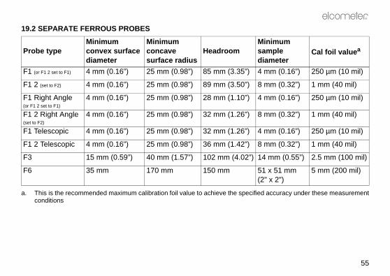
19.2 SEPARATE FERROUS PROBES
Probe typeMinimum convex surface diameter
Minimum concave surface radius
HeadroomMisadi
a. This is the recommended maximum calibration foil value to achieve the specifiedconditions
F1 (or F1 2 set to F1) 4 mm (0.16”) 25 mm (0.98”) 85 mm (3.35”) 4 m
F1 2 (set to F2) 4 mm (0.16”) 25 mm (0.98”) 89 mm (3.50”) 8 m
F1 Right Angle(or F1 2 set to F1)
4 mm (0.16”) 25 mm (0.98”) 28 mm (1.10”) 4 m
F1 2 Right Angle(set to F2)
4 mm (0.16”) 25 mm (0.98”) 32 mm (1.26”) 8 m
F1 Telescopic 4 mm (0.16”) 25 mm (0.98”) 32 mm (1.26”) 4 m
F1 2 Telescopic 4 mm (0.16”) 25 mm (0.98”) 36 mm (1.42”) 8 m
F3 15 mm (0.59”) 40 mm (1.57”) 102 mm (4.02”) 14
F6 35 mm 170 mm 150 mm 51(2

nimum mple meter
Cal foil valuea
accuracy under these measurement
m (0.24”) 250 µm (10 mil)
m (0.24”) 250 µm (10 mil)
m (0.24”) 250 µm (10 mil)
mm (0.55”) 1 mm (40 mil)
mm Any
Op_456_3_English.book Page 56 Thursday, January 22, 2009 8:05 PM
R
56
19.3 SEPARATE NON-FERROUS PROBES
Probe typeMinimum convex surface diameter
Minimum concave surface radius
HeadroomMisadia
a. This is the recommended maximum calibration foil value to achieve the specifiedconditions
N1 35 mm (1.38”) 25 mm (0.98”) 85 mm (3.35”) 6 m
N1 Right Angle 35 mm (1.38”) 25 mm (0.98”) 28 mm (1.10”) 6 m
N1A Anodiser’s Probe
35 mm (1.38”) 25 mm (0.98”) 85 mm (3.35”) 6 m
N2 100 mm (3.97”) 150 mm (5.90”) 85 mm (3.35”) 14
N6 Flat surface 400 mm 160 mm 58

R
57
nimum mple ameter
Cal foil valuea
accuracy under these measurement
m (0.32”) 250 µm (10 mil)
m (0.16”) 250 µm (10 mil)
m (0.32”) 250 µm (10 mil)
m (0.16”) 250 µm (10 mil)
Op_456_3_English.book Page 57 Thursday, January 22, 2009 8:05 PM
19.4 SEPARATE DUAL FNF
Probe typeMinimum convex surface diameter
Minimum concave surface radius
HeadroomMisadi
a. This is the recommended maximum calibration foil value to achieve the specifiedconditions
FNF1 (N) 38 mm (1.50”) 25 mm (0.98”) 88 mm (3.46”) 8 m
FNF1 (F) 4 mm (0.16”) 25 mm (0.98”) 88 mm (3.46”) 4 m
FNF1 Right Angle (N)
38 mm (1.50”) 25 mm (0.98”) 34 mm (1.34”) 8 m
FNF1 Right Angle (F)
4 mm (0.16”) 25 mm (0.98”) 34 mm (1.34”) 4 m

nimum mple meter
Cal foil valuea
accuracy under these measurement
m (0.16”) 250 µm (10 mil)
m (0.32”) 1 mm (40 mil)
mm (0.55”) 2.5 mm (100mil)
m (0.24”) 250 µm (10 mil)
m (0.32”) 250 µm (10 mil)
m (0.16”) 250 µm (10 mil)
Op_456_3_English.book Page 58 Thursday, January 22, 2009 8:05 PM
R
58
19.5 PINIP™ PROBES
Probe typeMinimum convex surface diameter
Minimum concave surface radius
HeadroomMisadia
a. This is the recommended maximum calibration foil value to achieve the specifiedconditions
F1 (or F1 2 set to F1) 4 mm (0.16”) 60 mm (2.36”) 155 mm (6.10”) 4 m
F1 2 (set to F2) 4 mm (0.16”) 60 mm (2.36”) 159 mm (6.25”) 8 m
F3 15 mm (0.59”) 45 mm (1.77”) 169 mm (6.65”) 14
N1 35 mm (1.38”) 50 mm (1.97”) 155 mm (6.09”) 6 m
FNF1 (N) 38 mm (1.50”) 55 mm (2.17”) 156 mm (6.15”) 8 m
FNF1 (F) 4 mm (0.16”) 55 mm (2.17”) 156 mm (6.14”) 4 m

R
59
Minimum access width
Overall length (headroom)
(0.24”) 150 mm (5.91”)
(0.24”) 260 mm (10.24”)
7 mm (0.28”) 145 mm (5.71”)
7 mm (0.28”) 250 mm (9.84”)
7 mm (0.28”) 140 mm (5.51”)
7 mm (0.28”) 245 mm (9.64”)
Op_456_3_English.book Page 59 Thursday, January 22, 2009 8:05 PM
19.6 SEPARATE MINIATURE FERROUS PROBES
Probe Type
Minimum convex surface diameter
Minimum concave surface radius
Minimum sample diameter
Minimum access height
F, Straight,45 mm (1.77”)
1.5 mm (0.06”) 6.5 mm (0.26”) 3 mm (0.12”) 6 mm
F, Straight,150 mm (5.9”)
1.5 mm (0.06”) 6.5 mm (0.26”) 3 mm (0.12”) 6 mm
F, 45°,45 mm (1.77”)
1.5 mm (0.06”) 6.5 mm (0.26”) 3 mm (0.12”) 18 mm (0.71”)
F, 45°,150 mm (5.9”)
1.5 mm (0.06”) 6.5 mm (0.26”) 3 mm (0.12”) 18 mm (0.71”)
F, 90°,45 mm (1.77”)
1.5 mm (0.06”) 6.5 mm (0.26”) 3 mm (0.12”) 16 mm (0.63”)
F, 90°,150 mm (5.9”)
1.5 mm (0.06”) 6.5 mm (0.26”) 3 mm (0.12”) 16 mm (0.63”)

Minimum access width
Overall length (headroom)
(0.24”) 150 mm (5.91”)
(0.24”) 260 mm (10.24”)
7 mm (0.28”) 145 mm (5.71”)
7 mm (0.28”) 250 mm (9.84”)
7 mm (0.28”) 140 mm (5.51”)
7 mm (0.28”) 245 mm (9.64”)
Op_456_3_English.book Page 60 Thursday, January 22, 2009 8:05 PM
R
60
19.7 SEPARATE MINIATURE NON-FERROUS PROBES
Probe TypeMinimum convex diameter
Minimum concave radius
Minimum sample diameter
Minimum access height
NF, Straight,45 mm (1.77”)
3 mm (0.12”) 25 mm (0.98”) 4 mm (0.16”) 6 mm
NF, Straight,150 mm (5.9”)
3 mm (0.12”) 25 mm (0.98”) 4 mm (0.16”) 6mm
NF, 45°,45 mm (1.77”)
3 mm (0.12”) 25 mm (0.98”) 4 mm (0.16”) 18 mm (0.71”)
NF, 45°,150 mm (5.9”)
3 mm (0.12”) 25 mm (0.98”) 4 mm (0.16”) 18 mm (0.71”)
NF, 90°,45 mm (1.77”)
3 mm (0.12”) 25 mm (0.98”) 4 mm (0.16”) 16 mm (0.63”)
NF, 90°,150 mm (5.9”)
3 mm (0.12”) 25 mm (0.98”) 4 mm (0.16”) 16 mm (0.63”)

R
61
. These messages are normally indicated by the message and
akege - return to Elcometer*.uge - remove probe and refit. ists, return to Elcometer*.ge - return to Elcometer*.uge - try new probe.ists, return to Elcometer*.lcometer*.odel F and gauge model N sed with a dual FNF probe. Elcometer* for software
adjustment required.
om electro-magnetic . Elcometer*.
Op_456_3_English.book Page 61 Thursday, January 22, 2009 8:05 PM
20 ERROR MESSAGES
Under certain conditions the gauge will display error messages (Figure 56)cleared by pressing any one of the softkeys. The cause of the error will beshould be corrected before proceeding.
Error message Causes Action to t#1 - PROBE Probe-to-gauge communication failure. Integral gau
Separate gaIf error pers
#2 - PROBE Corrupt data output from probe. Integral gauSeparate gaIf error pers
#3 - PROBE Internal error. Return to EPROBE UNSUPPORTED
a) Probe is dual FNF, but gauge is ferrous only, or non-ferrous only. See page 42.b) Old gauge software does not support new probe.
a) Gauge mcannot be ub) Return toupgrade.
PROBE CHANGED
Probe has been changed. Calibration
UNSTABLE READING
a) External electro-magnetic interference.b) Gauge faulty.
a) Isolate frinterferenceb) Return to

cted to gauge
ge off then on again.ists contact Elcometer..ists, return to Elcometer*.lcometer*.
ake
Op_456_3_English.book Page 62 Thursday, January 22, 2009 8:05 PM
R
62
* Contact Elcometer or your local Elcometer Supplier to arrange return.
Figure 56. Example error message - no probe is conne
VALUE TOO LARGE
Numerical error. Switch gauIf error pers
CALIBRATION Incorrect calibration calculation. Re-calibrateIf error pers
LANGUAGE MEMORY
Software error. Return to E
Error message Causes Action to t

R
63
Procedure, 2Point 29Procedure, Rough 29Procedure, Smooth 26Procedure, Special substrate 29
Calibration certificates 50Calibration methods
2 POINT 23AUSTRALIAN 24ISO 24ROUGH 23SET OFFSET 24SPECIAL SUB 23SSPC 24SWEDISH 24ZERO OFFSET 24
Character size 10Coated thickness standards 26
Spares 50Coatings
On galvanised steel 44On metallised steel 44
Coefficient of Variation 47Computer
Connection cable 51Computer, transferring data to 40
DData collection method 36
Counted average 37Normal 37
Data, activating 20Delete last reading 19
Op_456_3_English.book Page 63 Thursday, January 22, 2009 8:05 PM
21 INDEX
Numerics2 Point calibration method 2390/10 rule 32
AAccessories 49AS 2331.1.4 5AS 3894 24AS 3894.3-B 5AS/NZS 1580.108.1 5ASTM B 499 5ASTM D 1186-B 5ASTM D 1400 5ASTM D 7091 5ASTM E 376 5ASTM G 12 5Australian calibration method 24
BBatch mode 34Batches
Reviewing 38Batching 34
Creating new batch 35Data collection method 36Exiting 35Opening existing batch 37
BatteriesFitting 7Life of 48Precautions 45Rechargeable
Charging 49Life of 7
Specification 48Baud rate 21Beep
Changing volume 22Switching off 22
Bluetooth 40Icon in display 14Transferring readings 40
Bluetooth module 51BS 3900 (C5) 5BS 3900(C5) 5BS 5411 (11) 5BS 5411 (3) 5BS 5599 5
CCable
PC to gauge 51CAL softkey
Flashing 25Calibration
Adjustment 25Coated standards 25Coated thickness standards 26FNF probes 23Foils 25Locking 15Methods 23Shims 25
Calibration Adjustment 26

MemoryAmount available 39
Menu items2-POINT 23ABOUT 16AUSTRALIAN 24AUTO SWITCH OFF 21BACKLIGHT 15BAUD RATE 21BEEP VOLUME 22BLUETOOTH PC REPLY 21CAL METHOD 20CALIBRATION LOCKED 15CLEAR STATS 31CONTACT 16DATA 20DATA MENU 35DELETE 19DELETED READING 20DISPLAY 34ENLARGE STATS 31EXIT BATCHING 35EXTENDED MENU 18FACTORY CAL 16FREE MEMORY 39GAUGE INFORMATION 16HELP 16INTL GAUGE 16ISO 24LANGUAGES 22LARGE FONTS 22OPEN EXISTING BATCH 37OPEN NEW BATCH 35OPENING SCREEN 23OUTPUT 21
Op_456_3_English.book Page 64 Thursday, January 22, 2009 8:05 PM
R
64
Delete single batch 19Deleting readings
Permanent or tagged 20Dimensions 48DIN 50981 5DIN 50984 5Display
Changing size of fonts 22Character size 10Locking softkeys 22
EECCA T1 5EDTS+ Excel Link 40ElcoMaster 40Elcometer 456
Features 5Overview 4
EN 13523-1 5Error messages 61ESC 26Extended menu
Contents 19
FFactory calibration 16FNF 43Foils 25
Ordering 50
GGalvanised steel 44Gauge information 16
HHigh temperature 44Highest reading 47
IImmediate mode 34IMO MSC.215 (82/84) 5IMO, testing to standards of 32Interface 12
RS232 12International gauge settings 16ISO 1461 5ISO 19840 5, 24ISO 2063 5ISO 2360 5ISO 2808-12 5ISO 2808-7C 5ISO 2808-7D 5ISO calibration method 24
KKeypad 9
LLanguage, selecting 11Limits
Setting 39Lowest reading 47
MMaintenance 45Mean 47Measurement speed 48

R
65
What used for 42F1 2
High Temperature PINIP 44Substrate selection modes 21
F1 2 overview 44Fitting of 8FNF (Ferrous/Non-ferrous)
Substrate selection modes 21, 43What used for 43
Maximum temperature 48N (Non-ferrous)
What used for 43Performance 53PINIP
What used for 42Replacement of 46Wear of 46Which one to use? 43
PSPC readings90/10 rule 32About 32Transferring to ElcoMaster 42
QQuick-start 6
RReading screen 10
Typical 13Reading, taking 12Resetting the gauge 16Rough calibration method 23RS232 interface 12
Op_456_3_English.book Page 65 Thursday, January 22, 2009 8:05 PM
PRINT/OUTPUT 19PROBE 21PROBE INFORMATION 16RESET 16REVIEW BATCHES 38ROUGH 23RS232 BIT IMAGE 21RS232 PLAIN TEXT 22SELECT STATS 32SET LIMITS 39SET NDFT 32SET OFFSET 24SETUP 20SMOOTH 23SOFTKEY ENABLED 20SOFTKEYS LOCKED 22SPECIAL SUB 23SSPC 24STATISTICS 20STATS MENU 30STATS ON LCD 31SWEDISH 24TAG 20UNITS 21USA GAUGE 17ZERO OFFSET 24
MenusExtended off (simple) 15Extended on 18Overview 15Structure 18
Metallised steel 44Minimum substrate thickness 48Mode
Batch 34
Immediate 34
NNDFT, adjusting 32NF T30-124 5NSTM 631 5Number of readings 47
OOn/off 9Opening screen
Creating 45Disabling 23
PPackaging 49PIN 41PINIP probes
Fitting of 8High temperature 44
Power supply 48Printer
Miniprinter 51Printing
Batch of readings 19Statistical summary 19
Printing readings 21To Bluetooth 21
Probe positioning jig 50Probes 42
Adapters 50Capabilities 54–60Extending life of 46F (Ferrous)

Test certificates 50Test readings 28Testing calibration of gauge 29Tick box 14Transferring data to computer 40
BlueTooth 40
UUnits
Automatic setting of 21Manual setting of 21
Up/Down 14US gauge settings 17US NAVY NSI 009-32 5US NAVY PPI 63101-000 5
WWeight 48Welcome screen
Creating 45Disabling 23
Wrist harness, fitting of 52
ZZero offset calibration method 24
Op_456_3_English.book Page 66 Thursday, January 22, 2009 8:05 PM
R
66
SScale selection, F1 F2 21Screen
Welcome information 10Screen symbols
Battery condition 7Definition of 16
Screen symbols, explanation of 16Set offset 24Setting up the gauge 20Shims 25
Ordering 50Simple menu
Turning on/off 16Smooth calibration method 23SMS 6310-081-015 5Softkey
BACK 15CAL 13, 29
Flashing 14Procedure 26
DATA 35DATA COLLECTION METHOD 36ESC 26MENU 13SEL 14SET 27, 28TEST 26UP/DOWN 14ZERO 28
Software 40Data conversion 40ElcoMaster 40
Special sub calibration method 23SS 18 41 60 24
SSPC calibration method 24SSPC-PA 2 24SSPC-PA2 (2004) 5Standard deviation 47Standards 5
AS 3894 24Coated thickness 50ISO 19840 24SS 18 41 60 24SSPC-PA 2 24
StatisticsActivating 20Choice of 32Clearing 31Displaying on screen 31Dual function probes 34Increasing size on display 31Overview 30Terminology 47
Substrate selectionAutomatic 21, 43Manual 21, 43
Substrate thicknessMinimum 48
Swedish calibration method 24Switching on/off 9
Automatically 10, 21
TTemperature
Effect on measurement speed 48High, measuring of 44Operating 48Probes, maximum 48