Elcometer 121 4 Paint Inspection Gauge Pig Instruction Manual
27
English Elcometer 121/4 Paint Inspection Gauge Operating Instructions
-
Upload
masoodibrahim12 -
Category
Documents
-
view
87 -
download
2
description
elcometer
Transcript of Elcometer 121 4 Paint Inspection Gauge Pig Instruction Manual

Engl
ish
e
s
Elcometer 121/4
Paint Inspection Gaug
Operating Instruction

Engl
ish
R
is a registered trademaAll other trademarks acknowledged.
© Copyright Elcometer Limited 2009/20All rights reserved. No part of this Docu transcribed, stored (in a retrievalsystem or otherwise) or translated into means (electronic, mechanical,magnetic, optical, manual or otherwise Elcometer Limited.A copy of this Instruction Manual is ava www.elcometer.com.
Doc. No:TMA-0453 Issue 03Part No: 21339
R
rk of Elcometer Limited.10.ment may be reproduced, transmitted, any language, in any form or by any
) without the prior written permission ofilable for download on our Website via

R
1
Page. . . . . . . . . . . . . . . . . . . . . . . . 2. . . . . . . . . . . . . . . . . . . . . . . . 6. . . . . . . . . . . . . . . . . . . . . . . 12. . . . . . . . . . . . . . . . . . . . . . . 19. . . . . . . . . . . . . . . . . . . . . . . 22. . . . . . . . . . . . . . . . . . . . . . . 23. . . . . . . . . . . . . . . . . . . . . . . 24. . . . . . . . . . . . . . . . . . . . . . . 24. . . . . . . . . . . . . . . . . . . . . . . 25
CONTENTS
Section1 About your gauge . . . . . . . . . . . . . . . . . . . . . . . . . . . . . . . . . . . . . . . . 2 Measuring film thickness . . . . . . . . . . . . . . . . . . . . . . . . . . . . . . . . . . 3 [TOP] Measuring cross-cut adhesion . . . . . . . . . . . . . . . . . . . . . . . . 4 Fitting cutting tools. . . . . . . . . . . . . . . . . . . . . . . . . . . . . . . . . . . . . . . 5 Replacing batteries in the torch . . . . . . . . . . . . . . . . . . . . . . . . . . . . 6 Spare parts and accessories . . . . . . . . . . . . . . . . . . . . . . . . . . . . . . . 7 Maintenance . . . . . . . . . . . . . . . . . . . . . . . . . . . . . . . . . . . . . . . . . . . . 8 Technical data . . . . . . . . . . . . . . . . . . . . . . . . . . . . . . . . . . . . . . . . . . . 9 Related equipment . . . . . . . . . . . . . . . . . . . . . . . . . . . . . . . . . . . . . . .

Gauge (P.I.G.). Welcome to
pection equipment for coatingsevelopment through application
e of this gauge you now haveore information visit our website
Top gauge
R
2
Thank you for your purchase of this Elcometer 121/4 Paint InspectionElcometer.Elcometer are world leaders in the design, manufacture and supply of insand concrete. Our products cover all aspects of coating inspection, from dto post application inspection.The Elcometer 121/4 P.I.G. is a world beating product. With the purchasaccess to the worldwide service and support network of Elcometer. For mat www.elcometer.com
1 ABOUT YOUR GAUGE
The Elcometer 121/4 P.I.G. is a hand-held gauge that offers a quick,versatile method of coating examination and measurement in aportable, easy-to-use format.The gauge is available in two versions, Standard and Top:• Standard gauges can be used for microscopic coating
examination and destructive measurement of coating thickness.• Top gauges have the same functionality as standard gauges and
can also be used for cross hatch adhesion testing using optionaltools.
This manual describes the operation of both versions of the gauge;any differences between the function of the two versions arehighlighted in the text as [TOP] or [STANDARD].

R
3
trates, including wood, plastics,
d these Operating Instructions.ve any questions.
e for 3 cutting tools.dy of the gauge, allowing rapid
al cross hatch cutting tool.
Your gauge can be used on single or multiple coats on virtually all subsmetals etc.To maximise the benefits of your new gauge, please take some time to reaDo not hesitate to contact Elcometer or your Elcometer supplier if you ha
1.1 FEATURES• Lightweight and durable - anodised aluminium construction.• [STANDARD] The gauge holds a single cutting tool with built-in storag• [TOP] Cutting tools are mounted on a rotary tool holder within the bo
change from one test to the next.• [TOP] The tool holder accommodates three cutting tools plus an option• Built-in 50x microscope with rotatable graticule scale.• Bright white LED light - ensures clear vision through the microscope.• Small size - facilitates use of the gauge in confined areas.

ance with the following Nationalin accordance with some of the
rd Top
R
4
1.2 STANDARDSDepending upon model, the Elcometer 121/4 P.I.G. can be used in accordand International Standards (optional accessories will be required to test standards listed):
Standard Standa
AS 1580.108.2ASTM D4138-ADIN 50986ISO 2808-6B supersedes ISO 2808-5B and BS 3900-C5-5BASTM D 3359-BEN 13523-6 supersedes ECCA T6NF T30-123AS 1580.408.4AS 3894.9ISO 16276-2ISO 2409 supersedes BS 3900-E6, NF T30-038

R
5
odel TOP model
1.3 WHAT THE BOX CONTAINS• Elcometer 121/4 P.I.G., Top or Standard model• Cutting tools, 3x, supplied loose:
• Cutter #1• Cutter #4• Cutter #6
• Hexagonal wrench, 2.5 mm• Black marker pen• Wrist strap• Carrying case• Operating instructions• Calibration certificate for each cutter (if specified at
time of ordering)The gauge is packed in a cardboard package. Pleaseensure that this packaging is disposed of in anenvironmentally sensitive manner. Consult your localEnvironmental Authority for further guidance.
STANDARD m

R
6
2 MEASURING FILM THICKNESS
1. Mark the surface to be tested with a stroke of the blackmarker pen provided with your gauge. Note that there shouldalways be a distinct contrast between the colour of the penink and the coating; different pen ink colours may thereforebe required for dark coatings.
2. Fit/select the appropriate cutting tool - see page 19.3. Cut the coating at right-angles to the pen mark as follows:
Place the gauge on the specimen with both guidance wheelsin contact with the surface of the specimen (this ensures thatthe knife blade produces an exact vertical cut with no tilting toone side).Pull the gauge towards you and apply a little pressure. Slightpressure is normally sufficient to penetrate through to thesubstrate. Heavier pressure may be required for very thickcoatings and very hard surfaces.
4. Position the gauge vertically so that the microscope lens isover the cut.
5. Press and hold the light switch to illuminate the cut.6. Look through the microscope lens and rotate the focus
adjuster until the cut is visible clearly.
R
7
cale divisions are parallel to ther side is likely to be ragged.ber of graticule divisions.
hown in Table 1.
l #4 is:
ditions Table,” on page 9.
raticule scale factorle (µm) inch scale (mils)
10.50.1
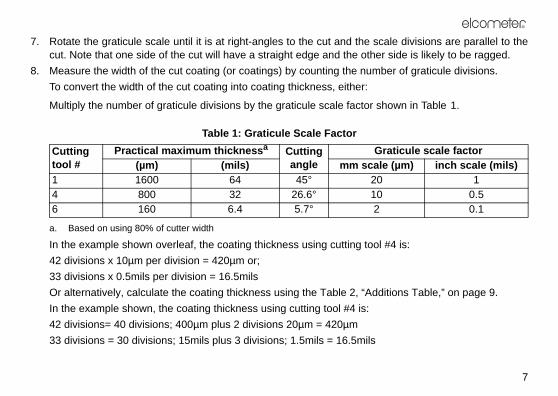
7. Rotate the graticule scale until it is at right-angles to the cut and the scut. Note that one side of the cut will have a straight edge and the othe
8. Measure the width of the cut coating (or coatings) by counting the numTo convert the width of the cut coating into coating thickness, either:
Multiply the number of graticule divisions by the graticule scale factor s
Table 1: Graticule Scale Factor
In the example shown overleaf, the coating thickness using cutting too42 divisions x 10µm per division = 420µm or;33 divisions x 0.5mils per division = 16.5milsOr alternatively, calculate the coating thickness using the Table 2, “AdIn the example shown, the coating thickness using cutting tool #4 is:42 divisions= 40 divisions; 400µm plus 2 divisions 20µm = 420µm33 divisions = 30 divisions; 15mils plus 3 divisions; 1.5mils = 16.5mils
Cutting tool #
Practical maximum thicknessa
a. Based on using 80% of cutter width
Cutting angle
G(µm) (mils) mm sca
1 1600 64 45° 204 800 32 26.6° 106 160 6.4 5.7° 2

1.8
0.07 Pen Mark
Cut Coating
s
R
8
0.0 0.2 0.4 0.6 0.8 1.0 1.2 1.4 1.6
0.0 0.01 0.02 0.03 0.04 0.05 0.06
1DIV=0.02mm
1DIV=0.001 inch
27.27
Coating(uncut)
Exposedsubstrate
Count number of graticule division

R
9
Cutting tool #6
µm mils
2 0.1
4 0.2
6 0.3
8 0.4
10 0.5
12 0.6
14 0.7
16 0.8
18 0.9
20 1
40 2
60 3
80 4
100 5
120 6
140 7
160 8
Table 2: Additions Table
Graticule Divisions
Cutting tool #1 Cutting tool #4
µm mils µm mils
1 20 1 10 0.5
2 40 2 20 1.0
3 60 3 30 1.5
4 80 4 40 2.0
5 100 5 50 2.5
6 120 6 60 3.0
7 140 7 70 3.5
8 160 8 80 4.0
9 180 9 90 4.5
10 200 10 100 5.0
20 400 20 200 10
30 600 30 300 15
40 800 40 400 20
50 1000 50 500 25
60 1200 60 600 30
70 1400 70 700 35
80 1600 80 800 40

1.0 1.2 1.4 1.6 1.8
0.04 0.05 0.06
.02mm
1 inch
0.07
-layer Coating
R
10
2.1 MEASURING MULTI-LAYER COATINGSThe thickness of individual layerscan be calculated by measuringeach layer (see illustrationopposite).
2.2 IRREGULARITIESIrregularities can occur if very hard,brittle films, or films with insufficientadhesion to the substrate aretested. The following can arise andcan be avoided as follows.
IRREGULAR, SHELL-LIKE CUTMeasure to an imaginary straightline through the best estimate of thecentre of the irregular cut edgeusing the graticule scale. This willgive a mean value for thickness.
0.0 0.2 0.4 0.6 0.8
0.0 0.01 0.02 0.03
1DIV=0
1DIV=0.00
Typical Multi

R
11
POOR ADHESION (GIVES THE ILLUSION OF TOO LITTLE FILM THICKNESS)Despite the fact that the coating may have fractured at point ‘X’,always measure distance ‘A’ to obtain the thickness of thecoating (single layer of coating in this example).
NO SEPARATIONWhen measuring the thickness of clear varnish on wood, theremay be no visible demarcation between the coating and thesubstrate. If this is the case, soak the exposed wood grain witha dye solution (fountain pen ink). The coating will not absorb anydye, but the wood cells do. This enables the cut width to bemeasured.

scores through the coating rightde at right angles to each other comparing the grid of squares
nd types of coating (see “Crosslade.
r of cuts
)ISO - Soft substrates (wood, plaster)
2 mm - 6 cuts2 mm - 6 cuts3 mm - 6 cuts
R
12
3 [TOP] MEASURING CROSS-CUT ADHESION
The optional cross hatch cutting tool which can be fitted to the Top model down to the next coating layer or down to the substrate. Two cuts are maresulting in a grid of small squares. Adhesion is then assessed visually byagainst ISO, ASTM or Corporate Standards.
3.1 SELECTING CUTTING TOOLSA range of cross hatch cutting tools is available for different thicknesses ahatch cutting tools” on page 23). Use the table below to select the correct b
Coating Thickness Cutter blade - Numbe
(µm) (mils) ASTM - Metal substrates
ISO - Hard substrates (metal
0 to 50 0 to 2 1 mm - 11 cuts50 to 125 2 to 5 2 mm - 6 cuts> 125 > 5 x0 to 60 1 mm - 6 cuts61 to 120 2 mm - 6 cuts121 to 250 3 mm - 6 cuts

R
13
ool on the sample, press down tool towards you in one
t to make a series of parallel ly 20 mm long. Apply sufficient e that you cut through the strate.
3.2 FITTING THE CUTTING TOOLSee “Fitting a cross hatch cutting tool” on page 21.
3.3 TEST PROCEDURE
Step ISO ASTM
1 Place the cutting tool on the sample, press down gently and pull the tool towards you in one steady movement to make a series of parallel cuts approximately 20 mm long. Apply sufficient pressure to ensure that you cut right through the coating to the surface of the substrate.Note: If the substrate is wood or similar, makecuts at 45° to the direction of the grain.
Place the cutting tgently and pull thesteady movemencuts approximatepressure to ensurcoating to the sub

ool on the sample at 90° to the t step (1) to create a lattice ting.
rush, brush lightly to remove r ribbons of coating.
oating.
R
14
2 Place the cutting tool on the sample at 90° to the first cut and repeat step (1) to create a lattice pattern on the coating.
Place the cutting tfirst cut and repeapattern on the coa
3 Using a suitable brush, brush lightly several times forwards and several times backwards along the diagonals of the lattice to remove debris.
Using a suitable bdetached flakes o
4 Inspect to ensure the cuts have penetrated all the way through the c
Step ISO ASTM

R
15
hesive tape (see “Adhesive , remove and discard two adhesive tape. Remove an f tape at a steady rate and cut
ately 75 mm from this length.ce of tape over the lattice and using a finger. Rub the tape aser on the end of a pencil to sion between the tape and the
5 If the substrate is soft, jump to step (10).If the substrate is hard or wood, proceed to the next step (6)
-
6 Using suitable adhesive tape (see “Adhesive tape” on page 23), remove and discard two complete turns of adhesive tape. Remove an additional length of tape at a steady rate and cut a piece approximately 75 mm from this length.
Using suitable adtape” on page 23)complete turns ofadditional length oa piece approxim
7 Centre the cut piece of tape over the lattice and smooth into place using a finger. Rub the tape firmly using a finger nail or finger tip to ensure good adhesion between the tape and the coating.
Centre the cut piesmooth into placefirmly using the erensure good adhecoating.
Step ISO ASTM

s (± 30 seconds) of applying the tape by pulling in a single an angle of 180° to the coating
180°
R
16
8 Within 5 minutes of applying the tape, remove the tape by pulling in a single smooth action taking approximately 0.5 to 1 seconds at an angle of 60° to the coating surface.
Within 90 secondthe tape, remove smooth action at surface.
9 To maintain a permanent record of the test, retain the tape by applying it to a transparent film
-
Step ISO ASTM
60°

R
17
ing adhesion by viewing theg an illuminated magnifier.ice of cuts with the ISO and shown in “ISO and ASTMe 18.
10 Assess the coating adhesion by viewing thelattice of cuts in good light. If agreed, use an eyeglass to aid viewing.Compare the lattice of cuts with the ISO andASTM standards shown in “ISO and ASTMstandards” on page 18.
Assess the coatlattice of cuts usinCompare the lattASTM standardsstandards” on pag
11 Repeat the test at two other positionsNote: For full details of the test method, consult the standard.
Step ISO ASTM

ISO ASTMsquares of the 0 5B
the cuts. A 1 4B
ections of the t significantly
2 3B
r wholly in nt parts of the ut not
3 2B
ribbons and/or area than 65%, is
4 1B
ssification 4 5 0B
R
18
Table 3: ISO and ASTM standards
Surface DescriptionThe edges of the cuts are completely smooth; none of the lattice is detached.
Detachment of flakes of the coating at the intersections of cross cut area not significantly greater than 5% is affected.
The coating has flaked along the edges and/or at the interscuts. A cross cut area significantly greater than 5%, but nogreater than 15% is affected.
The coating has flaked along the edges of the cuts partly olarge ribbons, and/or it has flaked partly or wholly on differesquares. A cross cut area significantly greater than 15%, bsignificantly greater than 35%, is affected.
The coating has flaked along the edges of the cuts in large some squares have detached partly or wholly. A cross cut significantly greater than 35%, but not significantly greater affected.
Any degree of flaking that cannot be classified even by cla(1B).

R
19
e gauge with cutting tools fitted.h care.
b
a
c
4 FITTING CUTTING TOOLS
Always take care when handling cutting tools and when handling thCutting tools are very sharp and can cause injury if not handled wit
When fitting any cutting tool, ensure that the tool is inserted such thatthe highest point of the tool is closest to the wheels of the gauge asshown in the illustration.
4.1 [STANDARD] MODELS1. To remove a cutting tool, place the gauge on its side, loosen the
retaining screw (a) and then pull out the cutting tool.2. Spare cutting tools are stored in the body of the instrument. To
gain access to this built-in storage, unscrew the end cap (b) andinvert the gauge, taking care not to drop the cutters as they slideout (cutting tips can be damaged by impact). Replace the sparecutting tools and re-fit the end cap.
3. Fit the cutting tool (c), pushing it all the way into the recess. Wheninserted correctly the cutting tool should protrude from the base ofthe gauge the same extent as the wheels.
4. Tighten the retaining screw to secure the cutting tool.
auge for the first time you mustss hatch adhesion testing, also
Cutting tool selection wheel
R
20
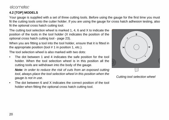
4.2 [TOP] MODELSYour gauge is supplied with a set of three cutting tools. Before using the gfit the cutting tools onto the cutter holder. If you are using the gauge for crofit the optional cross hatch cutting tool.The cutting tool selection wheel is marked 1, 4, 6 and X to indicate theposition of the tools in the tool holder (X indicates the position of theoptional cross hatch cutting tool - page 23).When you are fitting a tool into the tool holder, ensure that it is fitted inthe appropriate position (tool # 1 in position 1, etc.).The tool selection wheel is also marked with two dots:• The dot between 1 and 4 indicates the safe position for the tool
holder. When the tool selection wheel is in this position all thecutting tools are withdrawn into the body of the gauge.Note: In order to reduce the risk of cuts from an exposed cuttingtool, always place the tool selection wheel in this position when thegauge is not in use.
• The dot between 6 and X indicates the correct position of the toolholder when fitting the optional cross hatch cutting tool.
R
21
et that a cutting tool is already
graved with an X.fitting cutting tools but rotate thebefore mounting the tool.
b a
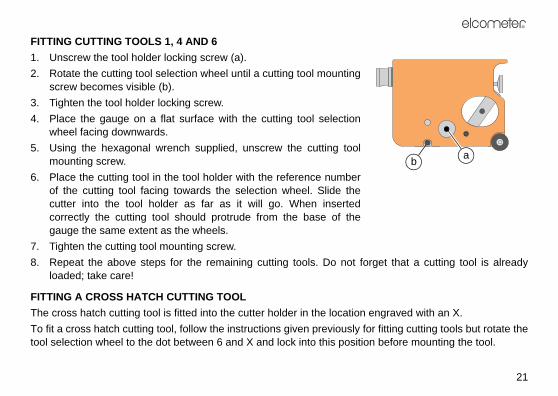
FITTING CUTTING TOOLS 1, 4 AND 61. Unscrew the tool holder locking screw (a).2. Rotate the cutting tool selection wheel until a cutting tool mounting
screw becomes visible (b).3. Tighten the tool holder locking screw.4. Place the gauge on a flat surface with the cutting tool selection
wheel facing downwards.5. Using the hexagonal wrench supplied, unscrew the cutting tool
mounting screw.6. Place the cutting tool in the tool holder with the reference number
of the cutting tool facing towards the selection wheel. Slide thecutter into the tool holder as far as it will go. When insertedcorrectly the cutting tool should protrude from the base of thegauge the same extent as the wheels.
7. Tighten the cutting tool mounting screw.8. Repeat the above steps for the remaining cutting tools. Do not forg
loaded; take care!
FITTING A CROSS HATCH CUTTING TOOLThe cross hatch cutting tool is fitted into the cutter holder in the location enTo fit a cross hatch cutting tool, follow the instructions given previously for tool selection wheel to the dot between 6 and X and lock into this position
p of the torch
a long period of time. This will
tion. Please consult your local
c
b
a
lustration shows [TOP] model)
R
22
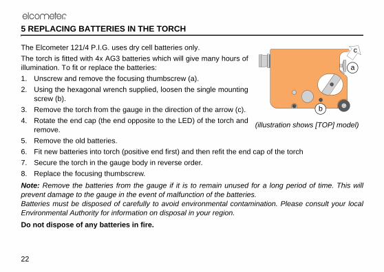
5 REPLACING BATTERIES IN THE TORCH
The Elcometer 121/4 P.I.G. uses dry cell batteries only.The torch is fitted with 4x AG3 batteries which will give many hours ofillumination. To fit or replace the batteries:1. Unscrew and remove the focusing thumbscrew (a).2. Using the hexagonal wrench supplied, loosen the single mounting
screw (b).3. Remove the torch from the gauge in the direction of the arrow (c).4. Rotate the end cap (the end opposite to the LED) of the torch and
remove.5. Remove the old batteries.6. Fit new batteries into torch (positive end first) and then refit the end ca7. Secure the torch in the gauge body in reverse order.8. Replace the focusing thumbscrew.Note: Remove the batteries from the gauge if it is to remain unused for prevent damage to the gauge in the event of malfunction of the batteries. Batteries must be disposed of carefully to avoid environmental contaminaEnvironmental Authority for information on disposal in your region.Do not dispose of any batteries in fire.
(il

R
23
or your local supplier:
6 SPARE PARTS AND ACCESSORIES
The following spare parts and optional items are available from Elcometer,
6.1 CUTTING TOOLSCutting tool #1 T99915761-1Cutting tool #4 T99915761-4Cutting tool #6 T99915761-6
6.2 CROSS HATCH CUTTING TOOLSCutting tool, 6 x 1 mm: T99913700-1Cutting tool 11 x 1 mm: T99913700-2Cutting tool 11x 1.5 mm: T99913700-3Cutting tool, 6 x 2 mm: T99913700-4Cutting tool, 6 x 3 mm: T99913700-5
6.3 MISCELLANEOUSBlack marker pen: T1214434-Carrying case: T12121191Hexagonal wrench, 2.5 mm: T9996287-
6.4 ADHESIVE TAPEAdhesive tape, ASTM D3359 1 Roll: K0001539M001Adhesive tape, ASTM D3359 2 Rolls: T9998894-Adhesive tape, ISO2409 1 Roll: K0001539M012Adhesive tape, ISO2409 2 Rolls: T9999358-
ce under normal operating and
, replace the battery.he unlikely event of a fault, thelcometer. The warranty will bed on the outside cover of these
es 7 & 12
’s reading
5oz)" x 3" x 1.2")1.6")
R
24
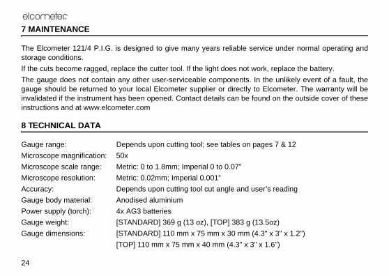
7 MAINTENANCE
The Elcometer 121/4 P.I.G. is designed to give many years reliable servistorage conditions.If the cuts become ragged, replace the cutter tool. If the light does not workThe gauge does not contain any other user-serviceable components. In tgauge should be returned to your local Elcometer supplier or directly to Einvalidated if the instrument has been opened. Contact details can be founinstructions and at www.elcometer.com
8 TECHNICAL DATA
Gauge range: Depends upon cutting tool; see tables on pagMicroscope magnification: 50xMicroscope scale range: Metric: 0 to 1.8mm; Imperial 0 to 0.07”Microscope resolution: Metric: 0.02mm; Imperial 0.001”Accuracy: Depends upon cutting tool cut angle and userGauge body material: Anodised aluminiumPower supply (torch): 4x AG3 batteriesGauge weight: [STANDARD] 369 g (13 oz), [TOP] 383 g (13.Gauge dimensions: [STANDARD] 110 mm x 75 mm x 30 mm (4.3
[TOP] 110 mm x 75 mm x 40 mm (4.3" x 3" x

R
25
e of other equipment for testing/4 P.I.G. may also benefit from
ebsite at www.elcometer.com
9 RELATED EQUIPMENT
In addition to the Elcometer 121/4 P.I.G., Elcometer produces a wide rangand measuring the characteristics of coatings. Users of the Elcometer 121the following Elcometer products:• Elcometer 157 Coating Thickness Gauge• Elcometer 195 Säberg Drill• Elcometer 456 Coating Thickness Gauge• Elcometer Coating Adhesion TestersFor further information contact Elcometer, your local supplier or visit our w