Surface plasmon polaritons (SPP): an alternative to cavity QED

General rights Copyright and moral rights for the publications made accessible in the public portal are retained by the authors and/or other copyright owners and it is a condition of accessing publications that users recognise and abide by the legal requirements associated with these rights.
Users may download and print one copy of any publication from the public portal for the purpose of private study or research.
You may not further distribute the material or use it for any profit-making activity or commercial gain
You may freely distribute the URL identifying the publication in the public portal If you believe that this document breaches copyright please contact us providing details, and we will remove access to the work immediately and investigate your claim.
Downloaded from orbit.dtu.dk on: Jan 26, 2022
Elastic scattering of surface plasmon polaritons: Modeling and experiment
Bozhevolnyi, Sergey I.; Coello, V.
Published in:Physical Review B Condensed Matter
Link to article, DOI:10.1103/PhysRevB.58.10899
Publication date:1998
Document VersionPublisher's PDF, also known as Version of record
Link back to DTU Orbit
Citation (APA):Bozhevolnyi, S. I., & Coello, V. (1998). Elastic scattering of surface plasmon polaritons: Modeling andexperiment. Physical Review B Condensed Matter, 58(16), 10899-10910.https://doi.org/10.1103/PhysRevB.58.10899
PHYSICAL REVIEW B 15 OCTOBER 1998-IIVOLUME 58, NUMBER 16
Elastic scattering of surface plasmon polaritons: Modeling and experiment
Sergey I. BozhevolnyiMikroelektronik Centret, Technical University of Denmark, Building 345 east, DK-2800 Lyngby, Denmark
Victor CoelloInstitute of Physics, Aalborg University, Pontoppidanstræde 103, DK-9220 Aalborg, Denmark
~Received 9 March 1998!
Elastic ~in-plane! scattering of surface plasmon polaritons~SPP’s! is modeled by considering isotropicpointlike scatterers whose responses to the incident SPP field are phenomenologically related to their effectivepolarizabilities. Numerical simulations of single, double, and multiple scattering are presented for randomlysituated scatterers showing the interplay between different orders of scattering and localization phenomena.Correlation between the scattering regimes and spatial Fourier spectra of the corresponding SPP intensitydistributions is considered. Various optical microcomponents~e.g., straight and curved micromirrors! formedby sets of point scatterers are also simulated, and the stability and dispersion of their characteristics areinvestigated. The appropriate experimental results for SPP scattering by both random and specially configuredsets of microscatterers are reported for two excitation wavelengths~594 and 633 nm! and different metal~silverand gold! films. The near-field optical images obtained are related to the calculated SPP intensity distributionsdemonstrating that the model developed can be successfully used in studies of SPP elastic scattering, e.g., todesign the microcomponents for SPP’s.@S0163-1829~98!07039-8#
onseex
nsdoroe
-s-e
tevetor-
th
ts-
altotntu
ince
-e
-
nted
er-re-
onse-as
fiber-
sed
ensticaceam
todia-ala
SPP
for-ndof
ents
a
I. INTRODUCTION
Surface plasmon polaritons~SPP’s!, i.e., collective oscil-lations of the surface electron density, can be excited alan interface between dielectric and metal, and reprequasi-two-dimensional waves with amplitudes decayingponentially into either of the neighbor media.1 Having thefield maximum at the interface, SPP’s are extremely setive to surface properties, a circumstance that attractegreat deal of attention to SPP’s from researchers in bbasic and applied areas of physics. Many fundamental perties of SPP’s have been studied theoretically and expmentally, and various applications~mostly for surface sensing! have been suggested during the first two decadeextensive investigations.1 The development of near-field optical microscopy2 has led to the significant increase in thinterest to the research in this area, because near-fieldniques open up an exciting possibility to directly observarious SPP properties~from resonance field enhancementpropagation and scattering! and to investigate these propeties with the spatial resolution on a nanometer scale.3
Different near-field techniques have been employed inaforementioned studies of SPP’s~overviews can be found inrecent papers by Bozhevolnyi, Smolyaninov, and Zaya4
and Smolyaninovet al.5!. However, a photon scanning tunneling microscope~PSTM!,6 in which an uncoated fiber tip isused to detect an evanescent field of the light being totinternally reflected at the sample surface, seems to bemost suitable technique for local and unobtrusive probingthe SPP field. It has been theoretically argued that, due torelatively low refractive index of optical fiber, such a tip cabe within certain approximations considered as a nonperbative probe of the electric-field intensity.7 Lately our de-tailed experimental investigations demonstrated convingly that, for the SPP being resonantly excited at a relativ
PRB 580163-1829/98/58~16!/10899~12!/$15.00
gnt-
i-a
thp-ri-
of
ch-
e
lyhef
he
r-
-ly
smooth surface, near-field optical images~obtained with anuncoated fiber tip! can be indeed directly related to the intensity distributions of the total SPP field, i.e., field of thexcited and~in-plane! scattered SPP’s.8 Hereafter, SPP scattering in the surface plane is denoted aselasticSPP scatter-ing, since SPP scattering into a free space is an unwaprocess leading to the additional~radiative! losses experi-enced by the SPP.
The progress in both understanding of local SPP propties and techniques available for their studies stimulatedsearch in various directions, one of them being investigatiof possibility for local controlling and directing SPP’s, espcially in the surface plane. Thus, local SPP excitation hbeen demonstrated by using a metal coated taperedprobe as a radiation source9 and by changing coupling conditions ~in the Kretschmann configuration! with individualsurface defects created by a direct-write PSTM-batechnique.5,10 In the latter work, elastic SPP scattering~in thesurface plane! by an artificial surface defect has also beattempted but with poor results. More pronounced elascattering of SPP’s has been observed with artificial surfstructures produced by means of electron-belithography.11 It is clear that anelasticmicroscatterer shouldbe relatively large and with smooth boundaries in ordermaximize the scatterer’s strength while preserving an abatic perturbation. We believe that film materimodification5,10 can hardly be used for fabricating suchscatterer as the influence of material properties on thecharacteristics is known to be very strong.1 Quite recently,we have suggested a technique that relies on the local demation of a metal film surface with an uncoated fiber tip, ademonstrated its suitability for fabricating various setselastic microscatterers that act as micro-optical compon~e.g., micromirrors and microcavities! for SPP’s.12 Eventhough the main principle of our technique is simple,
10 899 © 1998 The American Physical Society

nontic
Png
edlt
anie-
ngor
urc
an
.eeero
co
thPre
rc
her
r
oe-s.rek
ti-u
io
stfiguled.ar
le,for
een. Inandarepre-Fi-ffer
PP
lin-ri-
ncebe-
en-PP
albe-
lane-ll-ved
withrical
nes
canm.deentwed
lar-eldof
., atr-
-acethe
ude
ns,ur-f
10 900 PRB 58SERGEY I. BOZHEVOLNYI AND VICTOR COELLO
proper modeling is desirable to develop a better understaing of operation of this kind of microcomponents. Dispersiof microcomponents and the stability of their characterisare among the issues to be clarified~preferably both experi-mentally and theoretically!.
Another research direction is concerned with elastic Sscattering byrandomlysituated scatterers and the resultilocalization phenomena, viz., weak and strong~Anderson!localization of SPP’s.13 Localization phenomena are causby interference in multiple elastic scattering that resuin the reduction of the mean free path.14 Actually, stronglocalization implies that the mean free path vanishespropagation no longer exists, and this requires rather efficmultiple scattering. Weak localization~or enhanced backscattering! arises from a constructive interference~in thebackscattering direction! between two waves scattered alothe same path in the opposite directions, and, therefshows up already in double scattering.15 Since the SPP fieldis strongly confined in the direction perpendicular to the sface plane, localization phenomena in the elastic SPP stering can be observed only with near-field techniques. Mfeatures of SPP localization have been clarified,13,16 but aproper way of the interpretation of experimental results, inear-field optical images, is yet to be developed and justifiNumerical simulations for various configurations of scatters and different orders of scattering would certainty begreat help in this case.
SPP scattering by surface inhomogeneities has beensidered in many theoretical papers~a good overview can befound in a paper by Pinceminet al.17!. In general, this prob-lem is very complicated, and even a fairly simple case ofSPP scattering, i.e., the scattering of a homogeneous SPa circularly symmetric defect on a metal surface, requielaborate numerical simulations.18 The approximation ofpointlike dipolar scatterers has been recently used to desclocal excitation and scattering of SPP’s out of the surfaplane19 as well as to simulate localization effects.20 In thelatter work, the indirect coupling between dipoles via texcitation of SPP’s has been neglected, thus making thesults obtained of limited use. As far as the elastic~in thesurface plane! SPP scattering is concerned, we should beamind that the scattering observed experimentally12 was closeto isotropic. Isotropic scatterers have been also pointedas a limiting case of small scatterers in a rigorous considation of SPP scattering,18 and used in rather simplified simulations of SPP excitation with individual surface defect5
Taking this into account one can approximate a scatteSPP by a cylindrical SPP, which is described by the Hanfunction with the lowest angular number (m50) and withthe wave number determined by the same dispersion relaas for a plane SPP.21 Such an approach allows one to circumvent the very complicated problem of SPP scattering by sface inhomogeneities and concentrate the efforts on varphenomena that were experimentally observed in~multiple!elastic SPP scattering.4,8,11–13,16
In this paper, we present numerical simulations of elaSPP scattering by randomly located and specifically conured isotropic pointlike scatterers, and compare our calctions with the previously reported and additionally obtainexperimental results. The paper is organized as followsSec. II the main relationships used in our calculations
d-
s
P
s
dnt
e,
-at-y
.,d.-f
n-
ebys
ibee
e-
in
utr-
del
on
r-us
ic-
a-
Ine
given and explained. Numerical simulations of singdouble, and multiple scattering are presented on Sec. IIIrandomly situated scatterers showing the interplay betwdifferent orders of scattering and localization phenomenaSec. IV various optical microcomponents, such as planecurved micromirrors, formed by sets of point scatterersconsidered. The appropriate experimental results aresented and compared with our calculations in Sec. V.nally, in Sec. VI we summarize the results obtained and oour conclusions.
II. MODEL FOR ELASTIC SCATTERINGOF SURFACE POLARITONS
Our model is based on two assumptions, viz.,~i! the elas-tic scattering of SPP’s is dominant with respect to the Sscattering out of the surface plane, and~ii ! the SPP scatteredby an individual surface defect represents an isotropic cydrical SPP. The first assumption is justified by the expemental observations showing the appropriate interferepatterns, whose periods corresponded to the interferencetween the incident and scattered SPP’s,4,11–13,16and signal~tip-surface! distance dependencies, that exhibited expontial behavior related to the evanescent decay of the Sfield.8 In addition, recent theoretical results for an individusurface defect indicated that the elastic SPP scatteringcomes dominant over the scattering out of the surface pin the case of resonant SPP scattering.18 The second assumption is primarily based on the circumstance that wepronounced parabolic interference fringes were obserwith SPP scattering by individual defects.4,12 Such a patterncorresponds to the interference between the excited SPPa plane phase front and the scattered SPP with a cylindphase front.12 Furthermore, it has been theoretically showthat the scattering by a circularly symmetric defect becomisotropic for small scatterers.18
Having substantiated the main two assumptions, weproceed with the formulation of the scattering probleSince, in the regime of linear scattering, the field amplituof a scattered SPP is proportional to the field of an incidSPP at the site of the scatterer, surface defects can be vieas pointlike scatterers characterized by their effective poizabilities that relate phenomenologically the scattered fiamplitudes to the incident ones. In addition, the geometryelastic SPP scattering is essentially two-dimensional, i.eany surface coordinater , the total SPP field being a supeposition of cylindrical SPP’s with the same wave numberb~equal to that of a plane SPP!21 exhibit the same spatial dependence along the direction perpendicular to the surfplane. Therefore, the well-known exponential decays ofSPP field into the neighbor media1 will be omitted, and thetotal SPP field will be represented hereafter by its magnitE(r ) at the surface plane.
Taking into account the aforementioned consideratiothe main relation for the total SPP field at an arbitrary sface pointr , which does not coincide with the position oscatterers, can be written down as follows:
E~r !5E0~r !1(j 51
N
a jE~r j !G~r ,r j !, ~1!
at
nethe
sa
er--
bthulth
glerel
r
ble
n
eakin
gld
rers’
ay
ngr-tionl
dly,
the
tothemi-he
m
sid-ou-nts
ite
re-ost
be-
of.e.,the-the
ing
he
te
PRB 58 10 901ELASTIC SCATTERING OF SURFACE PLASMON . . .
with
G~r ,r j !5i
4H0
~1!~bur2r j u!,
whereE0 is the incident SPP field,a j is the effective polar-izability of the jth scatterer located at the surface coordinr j , N is the number of scatterers,H is the Hankel function,andb is the SPP propagation constant, which is determiby the dielectric constants of media that are adjacent tointerface. For example, for semi-infinite media on both sidof the air-metal interfaceb5(2p/l)@«/(«11)#0.5, wherelis the wavelength of light in air, and« is the dielectric con-stant of metal.1 The effective polarizabilitya is dimension-less, and corresponds to the scatterer’s strength as far aelastic SPP scattering is concerned. Using the far-fieldproximation for the Hankel function22 it is relatively straight-forward to express the total~elastic! cross sectionsof the scatterer18 via the effective polarizability: s5a2/@4 Re(b)#. Calculation of the polarizability or thecross section from the actual surface profile of the scatterrather complicated,18 and, in the following numerical simulations, we shall use the estimate ofa based on the experimental near-field optical images.4,12
The general relation for the total SPP field@Eq. ~1!# is aself-consistent equation of multiple scattering, and canused only after the self-consistent field at the sites ofscattersE(r j ) has been determined. The significance of mtiple SPP scattering should be considered in relation withratio between the SPP propagation lengthL5@2 Im(b)#21
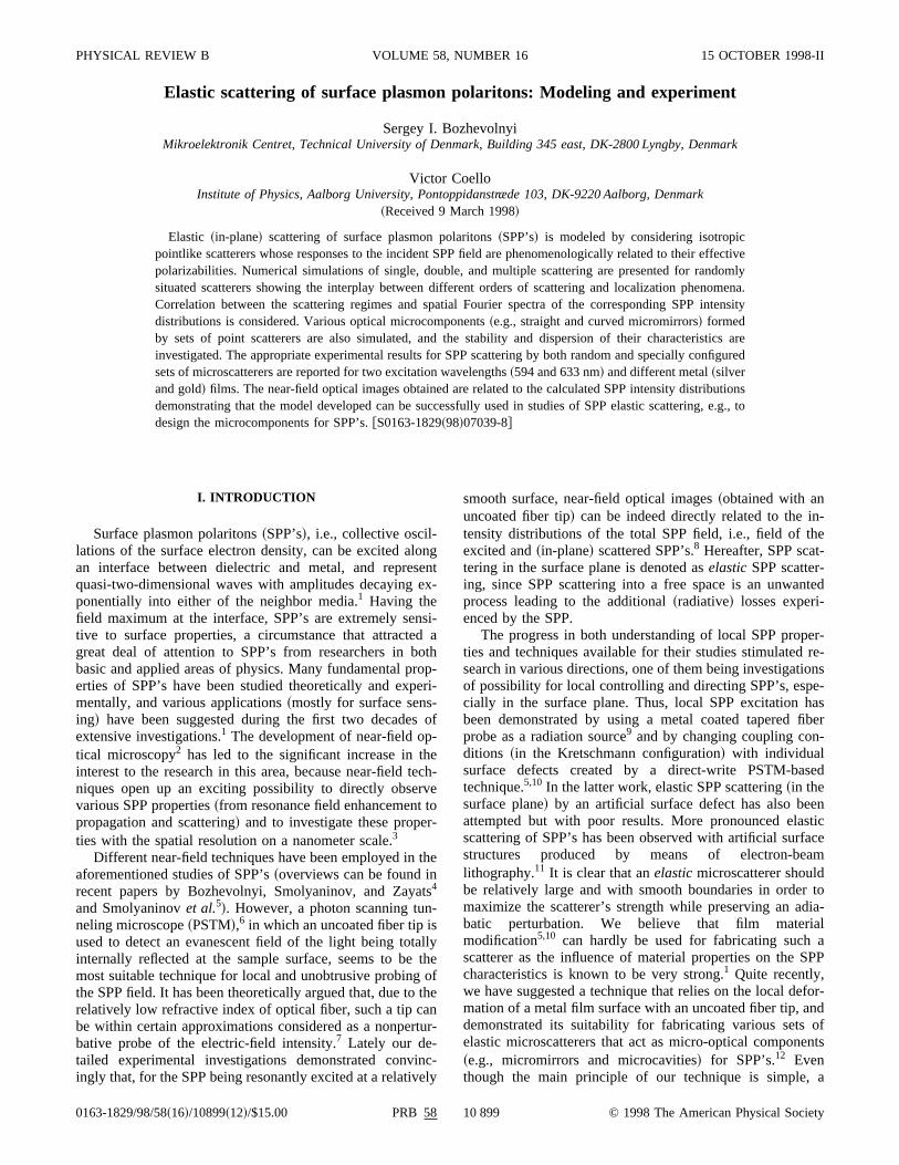
and the elastic scattering mean free pathl;R2/s, whereR isthe average separation between scatterers.13 If l .L, the re-gime of multiple scattering reduces to the regime of sinscattering@Fig. 1~a!#, and, consequently, the zeroth-ordBorn approximation can be used to evaluate the sconsistent field at the sites of the scatterers:E0(r j )5E0(r j ). As the SPP propagation length increases, the
FIG. 1. Schematic representation of different orders of scating: single~a!, double~b!, and multiple~c! scattering.
e
des
thep-
is
ee-e
e
f-
e-
gime of single scattering changes to the regime of douscattering@Fig. 1~b!#, when the following relation is valid:2l .L. l . In such a case, the first Born approximatioshould be invoked:
E1~r j !5E0~r j !1 (l 51,lÞ j
N
a lE0~r l !G~r j ,r l !. ~2!
Note that, for randomly situated scatterers, the effect of wSPP localization would become pronounced alreadydouble scattering.13–15
Finally, for L@ l , the regime of multiple SPP scatterinprevails@Fig. 1~c!#, and the successive Born iterations shoube used to calculate the self-consistent field at the scattesites:
En~r j !5E0~r j !1 (l 51,lÞ j
N
a lEn21~r l !G~r j ,r l !. ~3!
For randomly situated scatterers, multiple scattering meventually result in strong SPP localization.13 It should bealso borne in mind that, in the case of sufficiently stro~resonance! interaction, the Born iterations become divegent, and the exact solution of the self-consistent equahas to be employed.23 However, in the conducted numericasimulations, the Born series expansion converged rapiand a few iterations@typically, n,10 in Eq.~3!# were suffi-cient to obtain stable values of the self-consistent field atsites of the scatterers.
Closing the description of our model, we would likecomment on the difference in characteristics betweenSPP propagating along the air-metal interface of two seinfinite media and that of a thin metal layer placed on tsurface of a glass prism~this is typical for experimental in-vestigations!. The real part of the propagation constantbchanges only slightly~increases with the decrease of filthickness! for usual thicknesses (.30 nm).1 However, theSPP propagation length for a thin metal layer can be conerably less than that for semi-infinite media due to the cpling between the excited SPP and the field componepropagating in the prism~the radiation damping!.1 For thesake of simplicity, we shall use the relations for semi-infinmedia while keeping in mind the reduction ofL under ex-perimental conditions~due to the finite layer thickness!.
III. RANDOM SCATTERERS
Elastic SPP scattering by surface roughness and thesulting localization phenomena have been considered in mcases by using direct evaluation of~experimentally obtained!near-field optical images generated due to interferencetween the excited and scattered SPP’s.4,13,16 Quite recently,we have introduced the usage of spatial Fourier spectranear-field optical images for deciphering their content, ifor detection of the scattered SPP’s and evaluation ofscattering order.8 In the following, we shall confirm the previous observations and elucidate the relationship betweenFourier spectrum of intensity distribution and the scatterorder by using numerical simulations.
We begin with the estimation of the magnitude of teffective polarizabilitya for a typical individual scatterer to
r-

rine
ntiofre
t,
e
orc
b:idr-
al
na
ri-(ic
dela
totatio
-o
uest
e-ric
-c-edthnumtip
is-the
hof
is-u-
ibu-s
10 902 PRB 58SERGEY I. BOZHEVOLNYI AND VICTOR COELLO
be used in our calculations. This can be done by considethe characteristic interference pattern obtained experimtally with an individual scatterer and by fittinga so that thecalculated intensity distribution would have a similar cotrast. One should also remember to take into considerathe contrast correction factor that accounts for spatialquency filtration performed by a fiber tip.8 The result of thedescribed procedure is shown in Fig. 2 for the experimenwhich the SPP excited at the wavelength ofl5633 nmalong the air-metal interface of a silver film~thickness is;45 nm!,8,12,13 and for the simulations with the effectivpolarizability a53. The propagation constantb used inthese ~and following! simulations has been calculated fsemi-infinite media on both sides of the air-metal interfawith the metal dielectric constant«52161 i , which is atypical value for silver films and the wavelength ofl5633nm.8,13 The total elastic cross section of the scatterer canthen evaluated as described in the previous sections'0.22mm. Note that, for a symmetric surface defect consered theoretically,18 the same total cross section would corespond~in the first Born approximation! to the scattererwith the height of 0.1mm and the radius of 0.7mm. Theobtained parameters are similar to those of experimentobserved scatterers.4,12
In the following calculations we consider 25 equivalescatterers witha53, that are placed randomly in the are535 mm2 and illuminated by a plane wave (l5633 nm)propagating from the right side toward the left in the hozontal direction. In this case, the propagation lengthL;23 mm) is sufficiently large in comparison with the elastscattering mean free pathl;R2/s'4.5 mm. Therefore, byusing the Born approximations with different orders asscribed in the previous section, we can subsequently simuthe regimes of single~Fig. 3!, double~Fig. 4!, and multiple~Fig. 5! scattering. Experimentally, this would correspondthe usage of different wavelengths or/and different mefilms to change the relation between the SPP propagalength and the elastic scattering mean free path.13 Note that,in the following, the field intensity distribution in the immediate vicinity of a scatterer will be averaged over the area1503150 nm2 centered around the scatterer’s location~to
FIG. 2. Gray-scale topographical~a! and near-field optical~b!experimental images 334 mm2 along with the corresponding representation~c! of the calculated intensity distribution for the effetive polarizability a53. The experimental images were obtainwith the polariton excited at the wavelength of 633 nm alongsilver film. The depth of the topographical image is 96 nm. Cotrast, i.e., the relative difference between maximum and minimsignal, of the near-field optical image recorded with the fiberhaving the contrast correction factor of;1.2 is 73%. Contrast inthe calculated intensity distribution is 90%.
gn-
-n-
in
e
e
-
ly
t
-te
ln
f
avoid anomalously large and physically meaningless valof the field intensity!. Finally, one should bear in mind thathe Fourier spectrumF(k) of an intensity distribution, whichis a real function of spatial variables, has Hermitian symmtry and, therefore, its magnitude distribution is symmetwith respect to the origin, i.e.,uF(2k)u5uF(k)u. For ex-
e-
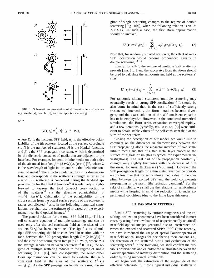
FIG. 3. Gray-scale representation of the total field-intensity dtribution ~a! and Fourier spectrum magnitudes corresponding tointensity distributions inside~b! and outside~c! of the scatterers’area. The intensity distribution within the area of 1035 mm2 wascalculated in the regime of single scattering by 25 scatters wita53 randomly distributed in the left half. Contrast of the images100%.
FIG. 4. Gray-scale representations of the total field-intensity dtribution ~a! calculated in the regime of double scattering and Forier spectrum magnitudes corresponding to the intensity distrtions inside~b! and outside~c! of the scatterers’ area. All else is ain Fig. 3.
in
c
thua
trien
trr
ne
ers
heumkatn-
plt
de
ble-
cies
anteri-sur-
ers’ionat-ould
ce-in
mhar-ter-r to
s ofong
shipec-e-evi-
g,
disndsts
ityf
PRB 58 10 903ELASTIC SCATTERING OF SURFACE PLASMON . . .
ample, the intensity interference pattern for two~unequal inamplitude! plane waves with wave vectorsk1 andk2 wouldresult in the Fourier spectrum, whose magnitude~besidesbeing nonzero atk50) has the same value fork56(k22k1). In the following, the spectrum magnitude at the orig~that corresponds to the average value of intensity! will benot shown on gray-scale representations of Fourier spe~to better visualize weak scattered waves!.
In the regime of single scattering, i.e., when the zeroorder Born approximation is applied, the intensity distribtion reflects the interference between the incident plane wand the scattered cylindrical waves@Fig. 3~a!#. Conse-quently, the spatial Fourier spectrum of the intensity disbution in the area, within which the scatterers are containrepresents a pair of open circles with the radius correspoing to the propagation constantb @Fig. 3~b!#.8 Outside of thescatterers’ area, a nearly plane~reflected! wave is formed,and it propagates in the specular direction with respecsome average boundary of the scattering region. The cosponding Fourier spectrum shows two bright spots aligalong the perpendicular to this boundary@Fig. 3~c!#.
In the regime of double scattering@the first Born approxi-mation, Eq.~2!#, the multiple interference effects becomalready pronounced:~i! scattered waves inside the scatterearea are significantly stronger than those outside [email protected]~a!#, ~ii ! their amplitudes are comparable with that of tincident wave thereby resulting in a diffuse Fourier spectr@Fig. 4~b!#, and ~iii ! outside of the scatterers’ area, a bacscattered wave~propagating in the direction opposite to thof the incident wave! is formed, and this wave is even stroger than the specularly reflected one@Fig. 4~c!#. These ef-fects become more pronounced in the regime of multiscattering~Fig. 5! when the successive iterations are usedcalculate the self-consistent field at the scatterers’ sites@Eq.~3!#. Note that, even though the intensity distribution insi
FIG. 5. Gray-scale representations of the total field-intensitytribution ~a! calculated in the regime of multiple scattering aFourier spectrum magnitudes corresponding to the intensity dibutions inside~b! and outside~c! of the scatterers’ area. All else ias in Fig. 3.
tra
--ve
-d,d-
toe-d
’
-
eo
the scatterers’ area is rather similar to the one for the douscattering regime@cf. Figs. 5~a! and 4~a!#, the correspondingFourier spectrum contains notably more spatial frequen@cf. Figs. 5~b! and 4~b!#. Actually, it represents a nearly filledcircle with the radius that is twice the propagation constb, a feature that is in a complete agreement with the expmental results obtained with SPP scattering on a roughface of gold film.8
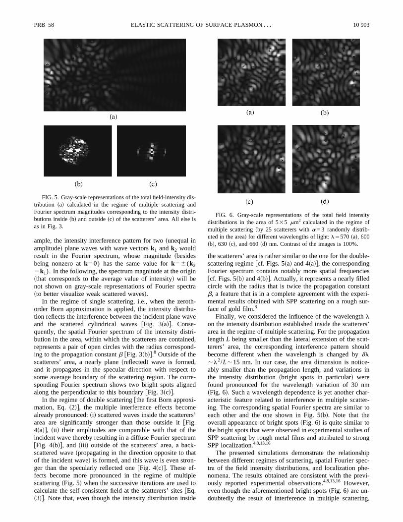
Finally, we considered the influence of the wavelengthlon the intensity distribution established inside the scatterarea in the regime of multiple scattering. For the propagatlengthL being smaller than the lateral extension of the scterers’ area, the corresponding interference pattern shbecome different when the wavelength is changed bydl;l2/L;15 nm. In our case, the area dimension is notiably smaller than the propagation length, and variationsthe intensity distribution~bright spots in particular! werefound pronounced for the wavelength variation of 30 n~Fig. 6!. Such a wavelength dependence is yet another cacteristic feature related to interference in multiple scating. The corresponding spatial Fourier spectra are similaeach other and the one shown in Fig. 5~b!. Note that theoverall appearance of bright spots~Fig. 6! is quite similar tothe bright spots that were observed in experimental studieSPP scattering by rough metal films and attributed to strSPP localization.4,8,13,16
The presented simulations demonstrate the relationbetween different regimes of scattering, spatial Fourier sptra of the field intensity distributions, and localization phnomena. The results obtained are consistent with the prously reported experimental observations.4,8,13,16 However,even though the aforementioned bright spots~Fig. 6! are un-doubtedly the result of interference in multiple scatterin
-
ri- FIG. 6. Gray-scale representations of the total field intensdistributions in the area of 535 mm2 calculated in the regime omultiple scattering~by 25 scatterers witha53 randomly distrib-uted in the area! for different wavelengths of light:l5570 ~a!, 600~b!, 630 ~c!, and 660~d! nm. Contrast of the images is 100%.

aal-iond-oo
gi
an-cr
ao
eae
h
etsi
sn
ro
laonltsbeeer
avo-
Mun
ne
e
-are
hern-ee-in-
alb--ted
cts,id-SPPntal
if-henre-andneto
2is
t ofsig-
of
-ith
3382
10 904 PRB 58SERGEY I. BOZHEVOLNYI AND VICTOR COELLO
they should not be directly related to strong localizationthe size (d55 mm) of the scatterers’ area used in our cculations is too small in comparison with the propagatlength (L;23 mm). Actually, the opposite relation shoulbe satisfied:d@L(@ l ). This is hardly a problem in the experiment but, as far as the calculations are concerned, cplying with this demand means an increase in numberscatterers to be considered by at least two orders of matude. Such extensive calculations are rather time consumand go beyond the frame of this work.
IV. TWO-DIMENSIONAL MICRO-OPTICS
The main idea of the technique that we suggestedexperimentally demonstrated12 is to line up several microscatterers with small separations in order to produce a mimirror. A curved line of scatterers would evidently producefocusing micromirror, and by using a proper combinationstraight and curved mirrors one should then be able to crvirtually any conceivable micro-optical circuit. Note that thoperation ofreflectiveoptical elements is inherently mucless sensitive to the light wavelength than that ofrefractiveones, because in the limit of geometrical optics the formare dispersionless. However, it is also clear from the outhat optical microcomponents, which consist of a few mcroscatterers and occupy an area of a few wavelengthsize, can exhibit relatively strong wavelength dispersion aconfigurational instability~i.e., instability with respect tovariations in geometrical parameters! in the overall scatteringbehavior.
The original idea was to model the aforementioned micelements by using the same relations@Eqs.~1! and~3!# as inthe previous section. However, we found that the calcutions performed within the zeroth-order Born approximatifitted somewhat better to the reported experimental resu12
than more accurate calculations with multiple scatteringing taken into account@Eq. ~3!#. We believe that this can bexplained by the fact that artificially fabricated microscatters are relatively large~micrometer-sized!12 and, therefore,~i! may respond differently~less efficiently! to the stronglydivergent scattered wave than to the incident plane wand/or ~ii ! may enhance the coupling from the exciting ttally internally reflected wave to the SPP~as is the case withindividual surface defects created by a direct-write PSTbased technique5,10!. These reasons can be taken into accoby introducing an additional term into Eq.~1! that is respon-sible only for the scattering of the incident~plane! wave:
E~r !5E0~r !1(j 50
N
a jE~r j !G~r ,r j !1(j 51
N
a j* E0~r j !G~r ,r j !,
~4!
wherea j* is the auxiliary~effective! polarizability of thejthscatterer accounting for the additional scattering chani.e., scattering of the incident fieldE0 that occurs along withmultiple scattering@described by Eq.~3!#. Note that the scat-tering by an individual scatterer shown in Fig. 2 is describby the effective polarizabilitya1a* , and, therefore, wehave used the conditiona1a* 53 ~see Sec. III! when com-paring the calculated and experimental results.
s
m-f
ni-ng
d
o-
fte
ret-ind
-
-
-
-
e
-t
l,
d
In the following calculations we consider optical microcomponents consisting of equivalent scatterers, thatplaced in the area 535 mm2 and illuminated by a planewave propagating from the right side toward the left in thorizontal direction. Using the experimental results conceing a corner square mirror~the most complicated structurcreated so far!12 we have found a very good agreement btween the experimental near-field optical image and thetensity distribution calculated witha52 and a* 51 @Eqs.~3! and ~4!#, whereas the simulations witha53 and a*50 @Eqs. ~3! and ~1!# resembled poorly the experimentimage~Fig. 7!. For this reason, the polarizability values otained (a52, a* 51) were used in our simulations of twodimensional optical microcomponents, that are presenhereafter. Finally, in order to elucidate the dispersion effetwo wavelengths of light, viz., 594 and 633 nm, are consered ~laser beams at these wavelengths were used forexcitation in our experiments presented in the experimepart of the paper!.
Simulation results for line micromirrors composed of dferent numbers of microscatterers are shown in Fig. 8. Wviewing the calculated intensity distributions one shouldmember that the interference fringes due to the excitedspecularly reflected wave are parallel to the mirror li~Wiener fringes!. We found that, even though it is possiblereflect the incident wave in the specular direction with only~pointlike! scatterers, the efficiency of a 2-scatterer mirrorsmall, and that there is practically no angular confinementhe reflected wave. Both efficiency and confinement arenificantly better for mirrors composed of 6~and larger num-ber of! scatterers. We found also that, for smaller number
FIG. 7. Gray-scale topographical~a! and near-field optical~b!experimental images 434 mm2 along with the corresponding representations of the calculated intensity distributions calculated wa53, a* 50 ~c!, anda52, a* 51 ~d!. The experimental imageswere obtained with the polariton excited at the wavelength of 6nm along the silver film. The depth of the topographical image isnm. Contrast of the optical images is 90%~b! and 100%~c! and~d!.
einnb
artotioe-
se ae-iteld-to
linet
rs
e
toeand
thedis-is
n-
ofingdis-icsber
d ofex-
blyeri-es
dis
dise
sity
PRB 58 10 905ELASTIC SCATTERING OF SURFACE PLASMON . . .
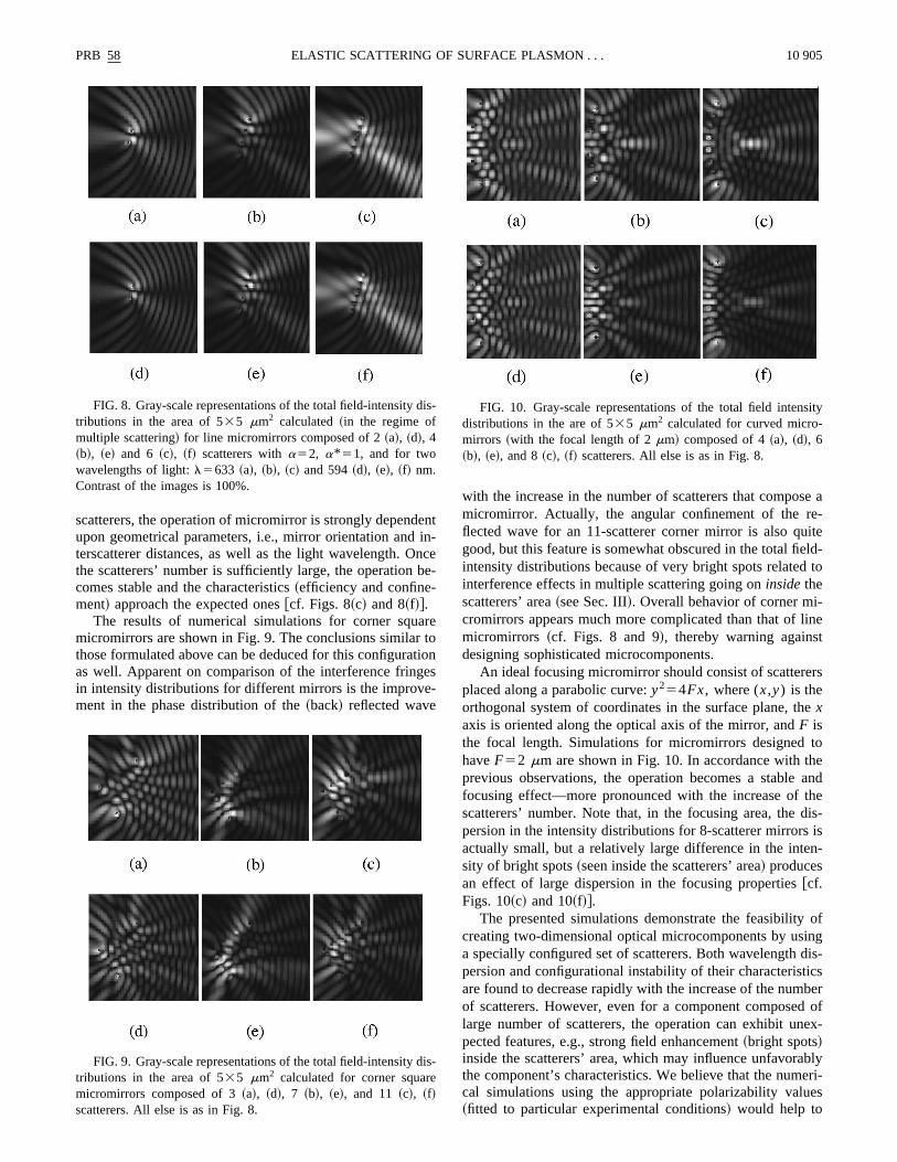
scatterers, the operation of micromirror is strongly dependupon geometrical parameters, i.e., mirror orientation andterscatterer distances, as well as the light wavelength. Othe scatterers’ number is sufficiently large, the operationcomes stable and the characteristics~efficiency and confine-ment! approach the expected ones@cf. Figs. 8~c! and 8~f!#.
The results of numerical simulations for corner squmicromirrors are shown in Fig. 9. The conclusions similarthose formulated above can be deduced for this configuraas well. Apparent on comparison of the interference fringin intensity distributions for different mirrors is the improvement in the phase distribution of the~back! reflected wave
FIG. 8. Gray-scale representations of the total field-intensitytributions in the area of 535 mm2 calculated~in the regime ofmultiple scattering! for line micromirrors composed of 2~a!, ~d!, 4~b!, ~e! and 6 ~c!, ~f! scatterers witha52, a* 51, and for twowavelengths of light:l5633 ~a!, ~b!, ~c! and 594~d!, ~e!, ~f! nm.Contrast of the images is 100%.
FIG. 9. Gray-scale representations of the total field-intensitytributions in the area of 535 mm2 calculated for corner squarmicromirrors composed of 3~a!, ~d!, 7 ~b!, ~e!, and 11 ~c!, ~f!scatterers. All else is as in Fig. 8.
nt-cee-
e
ns
with the increase in the number of scatterers that compomicromirror. Actually, the angular confinement of the rflected wave for an 11-scatterer corner mirror is also qugood, but this feature is somewhat obscured in the total fieintensity distributions because of very bright spots relatedinterference effects in multiple scattering going oninsidethescatterers’ area~see Sec. III!. Overall behavior of corner mi-cromirrors appears much more complicated than that ofmicromirrors ~cf. Figs. 8 and 9!, thereby warning againsdesigning sophisticated microcomponents.
An ideal focusing micromirror should consist of scattereplaced along a parabolic curve:y254Fx, where (x,y) is theorthogonal system of coordinates in the surface plane, thxaxis is oriented along the optical axis of the mirror, andF isthe focal length. Simulations for micromirrors designedhaveF52 mm are shown in Fig. 10. In accordance with thprevious observations, the operation becomes a stablefocusing effect—more pronounced with the increase ofscatterers’ number. Note that, in the focusing area, thepersion in the intensity distributions for 8-scatterer mirrorsactually small, but a relatively large difference in the intesity of bright spots~seen inside the scatterers’ area! producesan effect of large dispersion in the focusing [email protected]. 10~c! and 10~f!#.
The presented simulations demonstrate the feasibilitycreating two-dimensional optical microcomponents by usa specially configured set of scatterers. Both wavelengthpersion and configurational instability of their characteristare found to decrease rapidly with the increase of the numof scatterers. However, even for a component composelarge number of scatterers, the operation can exhibit unpected features, e.g., strong field enhancement~bright spots!inside the scatterers’ area, which may influence unfavorathe component’s characteristics. We believe that the numcal simulations using the appropriate polarizability valu~fitted to particular experimental conditions! would help to
-
-
FIG. 10. Gray-scale representations of the total field intendistributions in the are of 535 mm2 calculated for curved micro-mirrors ~with the focal length of 2mm! composed of 4~a!, ~d!, 6~b!, ~e!, and 8~c!, ~f! scatterers. All else is as in Fig. 8.
tice
feetta-s
o-94r
tho-
m
le
f
o
sintent
theen-oneantn
l-sig-
heallynm.arethe
e-
de-es
ti-
esn
theactob-
cedyityear-e it
suc-reby,theer
field
othandor-
dis-in-ially
faron
oftion-
imso
10 906 PRB 58SERGEY I. BOZHEVOLNYI AND VICTOR COELLO
fabricate the microcomponents with desirable characterisOur model seems reasonably simple and accurate to sadequately this purpose.
V. EXPERIMENTAL RESULTS
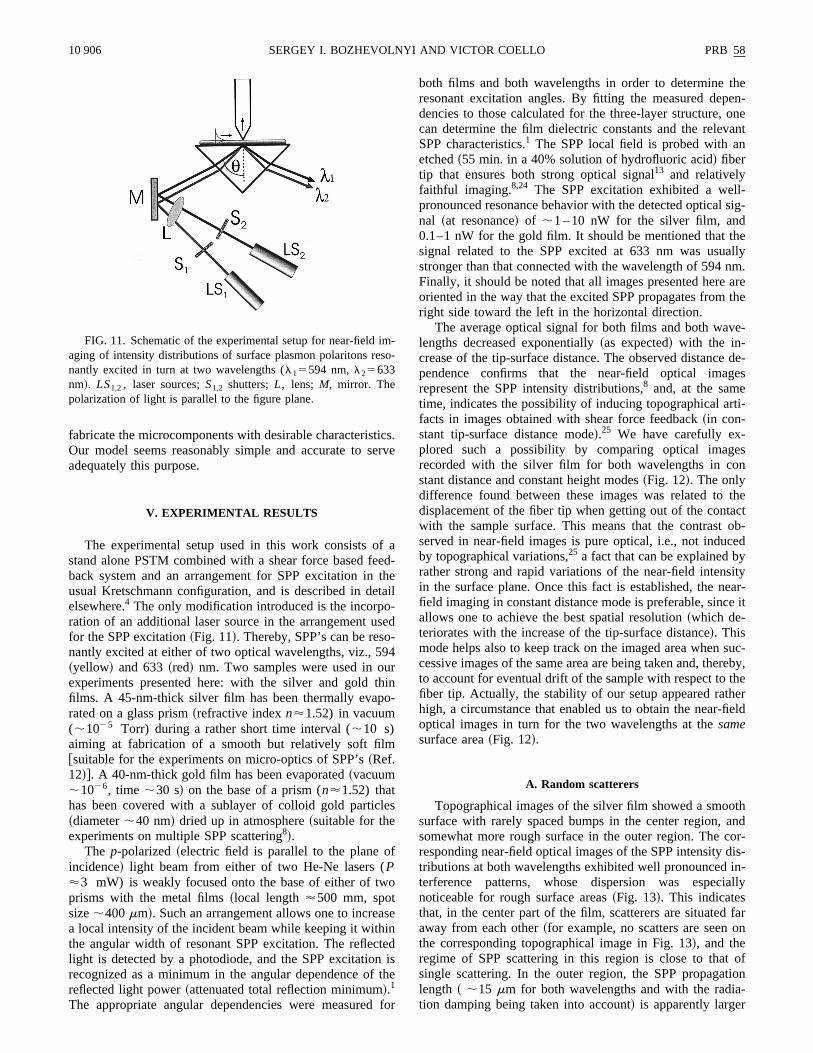
The experimental setup used in this work consists ostand alone PSTM combined with a shear force based fback system and an arrangement for SPP excitation inusual Kretschmann configuration, and is described in deelsewhere.4 The only modification introduced is the incorporation of an additional laser source in the arrangement ufor the SPP excitation~Fig. 11!. Thereby, SPP’s can be resnantly excited at either of two optical wavelengths, viz., 5~yellow! and 633~red! nm. Two samples were used in ouexperiments presented here: with the silver and goldfilms. A 45-nm-thick silver film has been thermally evaprated on a glass prism~refractive indexn'1.52) in vacuum(;1025 Torr) during a rather short time interval (;10 s)aiming at fabrication of a smooth but relatively soft fil@suitable for the experiments on micro-optics of SPP’s~Ref.12!#. A 40-nm-thick gold film has been evaporated~vacuum;1026, time ;30 s! on the base of a prism (n'1.52) thathas been covered with a sublayer of colloid gold partic~diameter;40 nm! dried up in atmosphere~suitable for theexperiments on multiple SPP scattering8!.
The p-polarized~electric field is parallel to the plane oincidence! light beam from either of two He-Ne lasers (P'3 mW) is weakly focused onto the base of either of twprisms with the metal films~local length'500 mm, spotsize;400mm!. Such an arrangement allows one to increaa local intensity of the incident beam while keeping it withthe angular width of resonant SPP excitation. The refleclight is detected by a photodiode, and the SPP excitatiorecognized as a minimum in the angular dependence ofreflected light power~attenuated total reflection minimum!.1
The appropriate angular dependencies were measured
FIG. 11. Schematic of the experimental setup for near-fieldaging of intensity distributions of surface plasmon polaritons renantly excited in turn at two wavelengths (l15594 nm,l25633nm!. LS1,2, laser sources;S1,2 shutters;L, lens; M, mirror. Thepolarization of light is parallel to the figure plane.
s.rve
ad-
heil
ed
in
s
e
dishe
for
both films and both wavelengths in order to determineresonant excitation angles. By fitting the measured depdencies to those calculated for the three-layer structure,can determine the film dielectric constants and the relevSPP characteristics.1 The SPP local field is probed with aetched~55 min. in a 40% solution of hydrofluoric acid! fibertip that ensures both strong optical signal13 and relativelyfaithful imaging.8,24 The SPP excitation exhibited a welpronounced resonance behavior with the detected opticalnal ~at resonance! of ;1 – 10 nW for the silver film, and0.1–1 nW for the gold film. It should be mentioned that tsignal related to the SPP excited at 633 nm was usustronger than that connected with the wavelength of 594Finally, it should be noted that all images presented hereoriented in the way that the excited SPP propagates fromright side toward the left in the horizontal direction.
The average optical signal for both films and both wavlengths decreased exponentially~as expected! with the in-crease of the tip-surface distance. The observed distancependence confirms that the near-field optical imagrepresent the SPP intensity distributions,8 and, at the sametime, indicates the possibility of inducing topographical arfacts in images obtained with shear force feedback~in con-stant tip-surface distance mode!.25 We have carefully ex-plored such a possibility by comparing optical imagrecorded with the silver film for both wavelengths in costant distance and constant height modes~Fig. 12!. The onlydifference found between these images was related todisplacement of the fiber tip when getting out of the contwith the sample surface. This means that the contrastserved in near-field images is pure optical, i.e., not induby topographical variations,25 a fact that can be explained brather strong and rapid variations of the near-field intensin the surface plane. Once this fact is established, the nfield imaging in constant distance mode is preferable, sincallows one to achieve the best spatial resolution~which de-teriorates with the increase of the tip-surface distance!. Thismode helps also to keep track on the imaged area whencessive images of the same area are being taken and, theto account for eventual drift of the sample with respect tofiber tip. Actually, the stability of our setup appeared rathhigh, a circumstance that enabled us to obtain the near-optical images in turn for the two wavelengths at thesamesurface area~Fig. 12!.
A. Random scatterers
Topographical images of the silver film showed a smosurface with rarely spaced bumps in the center region,somewhat more rough surface in the outer region. The cresponding near-field optical images of the SPP intensitytributions at both wavelengths exhibited well pronouncedterference patterns, whose dispersion was especnoticeable for rough surface areas~Fig. 13!. This indicatesthat, in the center part of the film, scatterers are situatedaway from each other~for example, no scatters are seenthe corresponding topographical image in Fig. 13!, and theregime of SPP scattering in this region is close to thatsingle scattering. In the outer region, the SPP propagalength ~ ;15 mm for both wavelengths and with the radiation damping being taken into account! is apparently larger
--
cgt
gha
he
alee
eri-ich
u-in
lePPl-m-rs,asgesthe
at,es
es
the
in-
itht asringh
thetter-on
-
t
s
he
Th
ges
e
PRB 58 10 907ELASTIC SCATTERING OF SURFACE PLASMON . . .
than the elastic scattering mean free path, and multiple stering results in bright spots whose position is wavelendependent~see Sec. III!.
Topographical images of the gold film showed a rousurface revealing the sublayer of randomly located gold pticles ~or particle clusters!.8 The elongated appearance of t
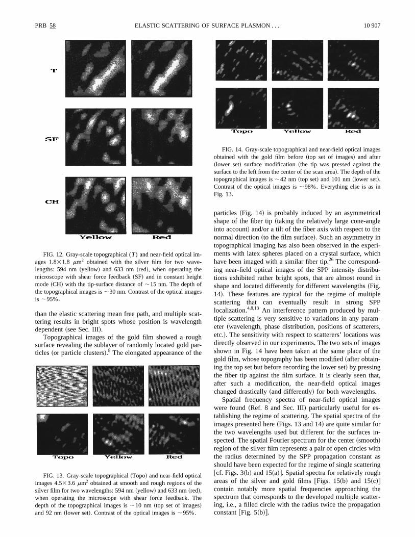
FIG. 12. Gray-scale topographical (T) and near-field optical im-ages 1.831.8 mm2 obtained with the silver film for two wavelengths: 594 nm~yellow! and 633 nm~red!, when operating themicroscope with shear force feedback~SF! and in constant heighmode~CH! with the tip-surface distance of;15 nm. The depth ofthe topographical images is;30 nm. Contrast of the optical imageis ;95%.
FIG. 13. Gray-scale topographical~Topo! and near-field opticalimages 4.533.6 mm2 obtained at smooth and rough regions of tsilver film for two wavelengths: 594 nm~yellow! and 633 nm~red!,when operating the microscope with shear force feedback.depth of the topographical images is;10 nm ~top set of images!and 92 nm~lower set!. Contrast of the optical images is;95%.
at-h
r-
particles~Fig. 14! is probably induced by an asymmetricshape of the fiber tip~taking the relatively large cone-anglinto account! and/or a tilt of the fiber axis with respect to thnormal direction~to the film surface!. Such an asymmetry intopographical imaging has also been observed in the expments with latex spheres placed on a crystal surface, whhave been imaged with a similar fiber tip.26 The correspond-ing near-field optical images of the SPP intensity distribtions exhibited rather bright spots, that are almost roundshape and located differently for different wavelengths~Fig.14!. These features are typical for the regime of multipscattering that can eventually result in strong Slocalization.4,8,13 An interference pattern produced by mutiple scattering is very sensitive to variations in any paraeter ~wavelength, phase distribution, positions of scattereetc.!. The sensitivity with respect to scatterers’ locations wdirectly observed in our experiments. The two sets of imashown in Fig. 14 have been taken at the same place ofgold film, whose topography has been modified~after obtain-ing the top set but before recording the lower set! by pressingthe fiber tip against the film surface. It is clearly seen thafter such a modification, the near-field optical imagchanged drastically~and differently! for both wavelengths.
Spatial frequency spectra of near-field optical imagwere found~Ref. 8 and Sec. III! particularly useful for es-tablishing the regime of scattering. The spatial spectra ofimages presented here~Figs. 13 and 14! are quite similar forthe two wavelengths used but different for the surfacesspected. The spatial Fourier spectrum for the center~smooth!region of the silver film represents a pair of open circles wthe radius determined by the SPP propagation constanshould have been expected for the regime of single scatte@cf. Figs. 3~b! and 15~a!#. Spatial spectra for relatively rougareas of the silver and gold films@Figs. 15~b! and 15~c!#contain notably more spatial frequencies approachingspectrum that corresponds to the developed multiple scaing, i.e., a filled circle with the radius twice the propagaticonstant@Fig. 5~b!#.
e
FIG. 14. Gray-scale topographical and near-field optical imaobtained with the gold film before~top set of images! and after~lower set! surface modification~the tip was pressed against thsurface to the left from the center of the scan area!. The depth of thetopographical images is;42 nm ~top set! and 101 nm~lower set!.Contrast of the optical images is;98%. Everything else is as inFig. 13.
nd.rth
p
a
l
u
verwstionlated
theere.reas
en-
ter,orsuldweingtipt tiphehen of
thea 3-erer
-to
othndre
s
e
r
l
ges
s
10 908 PRB 58SERGEY I. BOZHEVOLNYI AND VICTOR COELLO
B. Microcomponents for SPP’s
The technique that has been suggested for fabricatiomicrocomponents for SPP’s12 is rather simple: an uncoatefiber tip has to be pressed against a metal film surfacemeans that the sample should be moved toward the fibesufficiently fast in comparison with the time response ofshear force feedback system (;1 ms, in our case!. In thefirst experiments, the fiber tip has been moved with theezoelectric translator controlled manually.12 In the presentexperiments, we used a piezodriver~Physik Instrumente,Germany! whose output can be controlled with an externanalog signal. We have constructed a simpleRC-circuit withan adjustable power supply, that delivers voltage pulses~du-ration;10 ms! to the input of piezo driver. After a few triaexperiments we found that the voltage pulses of;1.5 Vresult in the microscatterers of a proper size~similar to thatobtained in the preliminary experiments12!. Note that, eventhough microscatterers with nearly the same efficiency co
FIG. 15. Gray-scale logarithmic representations of Fourier sptrum magnitudes for the near-field optical images~Figs. 13 and 14!recorded at smooth~a! and rough~b! regions of the silver film andwith the gold film before modification~c!.
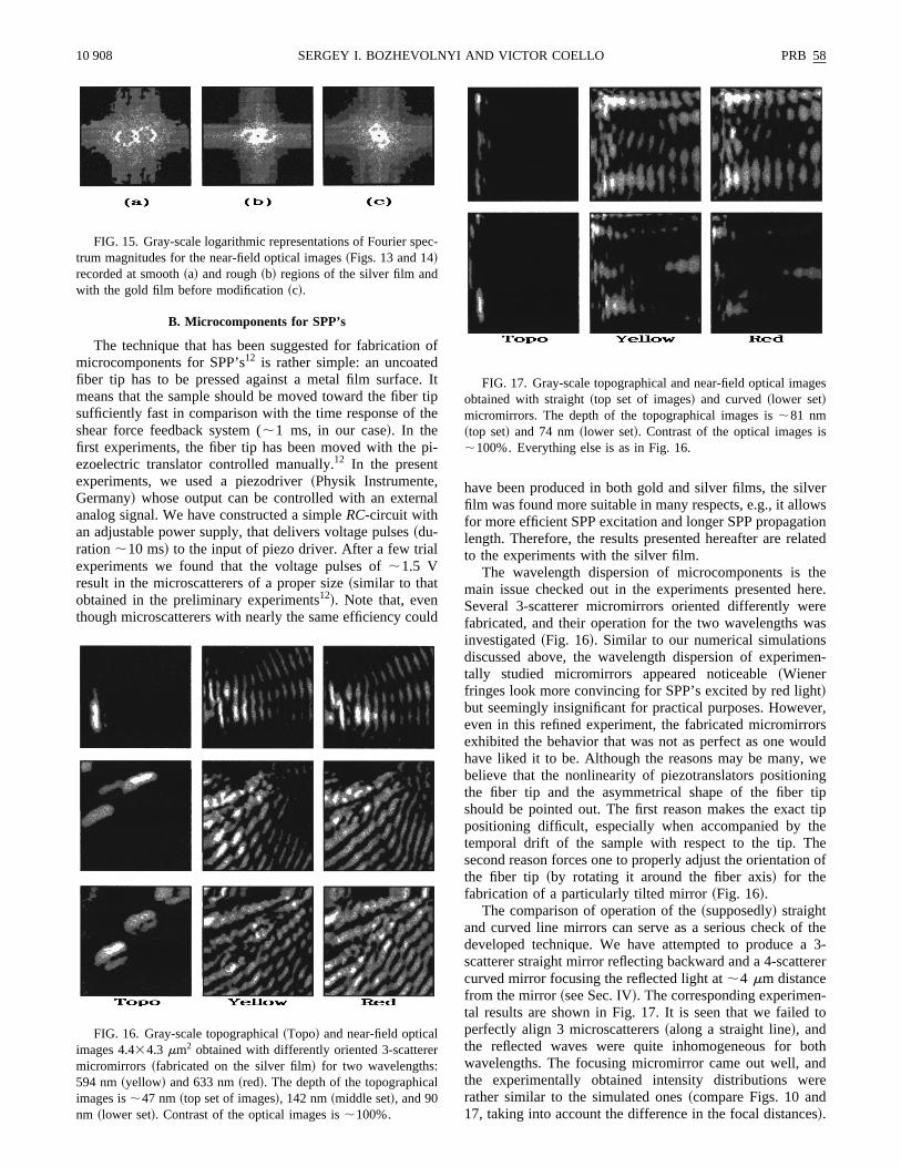
FIG. 16. Gray-scale topographical~Topo! and near-field opticalimages 4.434.3 mm2 obtained with differently oriented 3-scatteremicromirrors ~fabricated on the silver film! for two wavelengths:594 nm~yellow! and 633 nm~red!. The depth of the topographicaimages is;47 nm~top set of images!, 142 nm~middle set!, and 90nm ~lower set!. Contrast of the optical images is;100%.
of
Ittipe
i-
l
ld
have been produced in both gold and silver films, the silfilm was found more suitable in many respects, e.g., it allofor more efficient SPP excitation and longer SPP propagalength. Therefore, the results presented hereafter are reto the experiments with the silver film.
The wavelength dispersion of microcomponents ismain issue checked out in the experiments presented hSeveral 3-scatterer micromirrors oriented differently wefabricated, and their operation for the two wavelengths winvestigated~Fig. 16!. Similar to our numerical simulationsdiscussed above, the wavelength dispersion of experimtally studied micromirrors appeared noticeable~Wienerfringes look more convincing for SPP’s excited by red ligh!but seemingly insignificant for practical purposes. Howeveven in this refined experiment, the fabricated micromirrexhibited the behavior that was not as perfect as one wohave liked it to be. Although the reasons may be many,believe that the nonlinearity of piezotranslators positionthe fiber tip and the asymmetrical shape of the fibershould be pointed out. The first reason makes the exacpositioning difficult, especially when accompanied by ttemporal drift of the sample with respect to the tip. Tsecond reason forces one to properly adjust the orientatiothe fiber tip ~by rotating it around the fiber axis! for thefabrication of a particularly tilted mirror~Fig. 16!.
The comparison of operation of the~supposedly! straightand curved line mirrors can serve as a serious check ofdeveloped technique. We have attempted to producescatterer straight mirror reflecting backward and a 4-scattcurved mirror focusing the reflected light at;4 mm distancefrom the mirror~see Sec. IV!. The corresponding experimental results are shown in Fig. 17. It is seen that we failedperfectly align 3 microscatterers~along a straight line!, andthe reflected waves were quite inhomogeneous for bwavelengths. The focusing micromirror came out well, athe experimentally obtained intensity distributions werather similar to the simulated ones~compare Figs. 10 and17, taking into account the difference in the focal distance!.
c-
FIG. 17. Gray-scale topographical and near-field optical imaobtained with straight~top set of images! and curved~lower set!micromirrors. The depth of the topographical images is;81 nm~top set! and 74 nm~lower set!. Contrast of the optical images i;100%. Everything else is as in Fig. 16.
nPpaf
n
id-
erw
ind
s
su
eWiro,,
oped
ulal
r-
atse
ab-are
tion--extntinili-
rti-oth
een
di-.ical
eza-a ofenndted
ran-enafas-ena
ime
intandThe
and
m-sedAo-me
thee
and
-ear-to
for-
ing,
th
tht
PRB 58 10 909ELASTIC SCATTERING OF SURFACE PLASMON . . .
As far as the wavelength dispersion of the straight acurved micromirrors is concerned, the plane-reflected SPsomewhat more homogeneous for yellow light, but the stial confinement of the focused reflected SPP looks betterred light ~Fig. 17!.
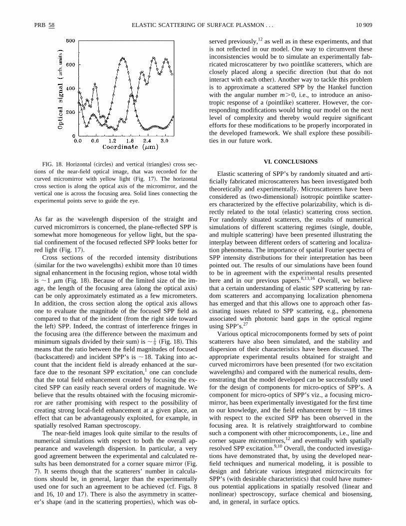
Cross sections of the recorded intensity distributio~similar for the two wavelengths! exhibit more than 10 timessignal enhancement in the focusing region, whose total wis ;1 mm ~Fig. 18!. Because of the limited size of the image, the length of the focusing area~along the optical axis!can be only approximately estimated as a few micrometIn addition, the cross section along the optical axis alloone to evaluate the magnitude of the focused SPP fieldcompared to that of the incident~from the right side towardthe left! SPP. Indeed, the contrast of interference fringesthe focusing area~the difference between the maximum aminimum signals divided by their sum! is ; 1
9 ~Fig. 18!. Thismeans that the ratio between the field magnitudes of focu~backscattered! and incident SPP’s is;18. Taking into ac-count that the incident field is already enhanced at theface due to the resonant SPP excitation,1 one can concludethat the total field enhancement created by focusing thecited SPP can easily reach several orders of magnitude.believe that the results obtained with the focusing micromror are rather promising with respect to the possibilitycreating strong local-field enhancement at a given placeeffect that can be advantageously exploited, for examplespatially resolved Raman spectroscopy.
The near-field images look quite similar to the resultsnumerical simulations with respect to both the overall apearance and wavelength dispersion. In particular, a vgood agreement between the experimental and calculatesults has been demonstrated for a corner square mirror~Fig.7!. It seems though that the scatterers’ number in calctions should be, in general, larger than the experimentused one for such an agreement to be achieved~cf. Figs. 8and 16, 10 and 17!. There is also the asymmetry in scatteer’s shape~and in the scattering properties!, which was ob-
FIG. 18. Horizontal~circles! and vertical~triangles! cross sec-tions of the near-field optical image, that was recorded forcurved micromirror with yellow light~Fig. 17!. The horizontalcross section is along the optical axis of the micromirror, andvertical one is across the focusing area. Solid lines connectingexperimental points serve to guide the eye.
dis-
or
s
th
s.sas
n
ed
r-
x-e
-fanin
f-ryre-
a-ly
served previously,12 as well as in these experiments, and this not reflected in our model. One way to circumvent theinconsistencies would be to simulate an experimentally fricated microscatterer by two pointlike scatterers, whichclosely placed along a specific direction~but that do notinteract with each other!. Another way to tackle this problemis to approximate a scattered SPP by the Hankel funcwith the angular numberm.0, i.e., to introduce an anisotropic response of a~pointlike! scatterer. However, the corresponding modifications would bring our model on the nlevel of complexity and thereby would require significaefforts for these modifications to be properly incorporatedthe developed framework. We shall explore these possibties in our future work.
VI. CONCLUSIONS
Elastic scattering of SPP’s by randomly situated and aficially fabricated microscatterers has been investigated btheoretically and experimentally. Microscatterers have bconsidered as~two-dimensional! isotropic pointlike scatter-ers characterized by the effective polarizability, which isrectly related to the total~elastic! scattering cross sectionFor randomly situated scatterers, the results of numersimulations of different scattering regimes~single, double,and multiple scattering! have been presented illustrating thinterplay between different orders of scattering and localition phenomena. The importance of spatial Fourier spectrSPP intensity distributions for their interpretation has bepointed out. The results of our simulations have been fouto be in agreement with the experimental results presenhere and in our previous papers.8,13,16 Overall, we believethat a certain understanding of elastic SPP scattering bydom scatterers and accompanying localization phenomhas emerged and that this allows one to approach othercinating issues related to SPP scattering, e.g., phenomassociated with photonic band gaps in the optical regusing SPP’s.27
Various optical microcomponents formed by sets of poscatterers have also been simulated, and the stabilitydispersion of their characteristics have been discussed.appropriate experimental results obtained for straightcurved micromirrors have been presented~for two excitationwavelengths! and compared with the numerical results, deonstrating that the model developed can be successfully ufor the design of components for micro-optics of SPP’s.component for micro-optics of SPP’s viz., a focusing micrmirror, has been experimentally investigated for the first tito our knowledge, and the field enhancement by;18 timeswith respect to the excited SPP has been observed infocusing area. It is relatively straightforward to combinsuch a component with other microcomponents, i.e., linecorner square micromirrors,12 and eventually with spatiallyresolved SPP excitation.9,10 Overall, the conducted investigations have demonstrated that, by using the developed nfield techniques and numerical modeling, it is possibledesign and fabricate various integrated microcircuitsSPP’s~with desirable characteristics! that could have numerous potential applications in spatially resolved~linear andnonlinear! spectroscopy, surface chemical and biosensand, in general, in surface optics.
e
ehe

y.
P.
.
s.
s.
t..
IE
l,
v.
pt
-
s
ine-
.
es,
et,
.
rn-
s.
ett.
10 910 PRB 58SERGEY I. BOZHEVOLNYI AND VICTOR COELLO
1Surface Polaritons,edited by V. M. Agranovich and D. L. Mills~North-Holland, Amsterdam, 1982!; H. Raether,Surface Plas-mons,Springer Tracts in Modern Physics, Vol. 111~Springer,Berlin, 1988!.
2Near Field Optics,edited by D. W. Pohl and D. Courjon~Kluwer,The Netherlands, 1993!.
3M. Specht, J. D. Pedarnig, W. M. Heckl, and T. W. Ha¨nsch, Phys.Rev. Lett.68, 476 ~1992!; O. Marti, H. Bielefeldt, B. Hecht, S.Herminghaus, P. Leiderer, and J. Mlynek, Opt. Commun.96,225~1993!; P. Dawson, F. de Fornel, and J.-P. Goudonnet, PhRev. Lett.72, 2927~1994!; D. P. Tsai, J. Kovacs, Z. Wang, MMoskovits, V. M. Shalaev, J. S. Suh, and R. Botet,ibid. 72,4149 ~1994!; R. B. G. de Hollander, N. F. van Hulst, and R.H. Kooyman, Ultramicroscopy57, 263 ~1995!; Y.-K. Kim, P.M. Lundquist, J. A. Helfrich, J. M. Mikrut, G. K. Wong, P. RAuvil, and J. B. Ketterson, Appl. Phys. Lett.66, 3407 ~1995!;Y.-K. Kim, J. B. Ketterson, and D. J. Morgan, Opt. Lett.21, 165~1996!.
4S. I. Bozhevolnyi, I. I. Smolyaninov, and A. V. Zayats, PhyRev. B51, 17 916~1995!.
5I. I. Smolyaninov, D. L. Mazzoni, J. Mait, and C. C. Davis, PhyRev. B56, 1601~1997!.
6R. C. Reddick, R. J. Warmack, and T. L. Ferrel, Phys. Rev. B39,767 ~1989!; D. Courjon, K. Sarayeddine, and M. Spajer, OpCommun. 71, 23 ~1989!; F. de Fornel, J. P. Goudonnet, LSalomon, and E. Lesniewska, Proc. SPIE1139, 77 ~1989!.
7D. Van Labeke and D. Barchiesi, J. Opt. Soc. Am. A10, 2193~1993!; R. Carminati and J.-J. Greffet, Opt. Commun.116, 316~1995!.
8V. Coello, S. I. Bozhevolnyi, and F. A. Pudonin, Proc. SP3098, 536 ~1997!.
9B. Hecht, H. Bielefeldt, L. Novotny, Y. Inouye, and D. W. PohPhys. Rev. Lett.77, 1889~1996!; B. Hecht, D. W. Pohl, and L.Novotny, inOptics at the Nanometer Scale,edited by M. Nieto-Vesperinas and N. Garcı´a ~Kluwer, Dordrecht, 1996!, p. 151.
10I. I. Smolyaninov, D. L. Mazzoni, and C. C. Davis, Phys. ReLett. 77, 3877~1996!.
11J. R. Krenn, R. Wolf, A. Leitner, and F. R. Aussenegg, OCommun.137, 46 ~1997!.
12S. I. Bozhevolnyi and F. A. Pudonin, Phys. Rev. Lett.78, 2823~1997!.
s.
.
13S. I. Bozhevolnyi, Phys. Rev. B54, 8177~1996!.14B. Souillard, inChance and Matter,edited by J. Souletie, J. Van
nimenus, and R. Stora~North-Holland, Amsterdam, 1987!, p.305; S. John, inScattering and Localization of Classical Wavein Random Media,edited by P. Sheng~World Scientific, Sin-gapore, 1990!, p. 1.
15M. P. van Albada, M. B. van der Mark, and A. Lagendijk,Scattering and Localization of Classical Waves in Random Mdia ~Ref. 14!, p. 97; Yu. N. Barabanenkovet al., in Progress inOptics,edited by E. Wolf~Elsevier, New York, 1991!, Vol. 29,p. 65.
16S. I. Bozhevolnyi, B. Vohnsen, I. I. Smolyaninov, and A. VZayats, Opt. Commun.117, 417 ~1995!; S. I. Bozhevolnyi, A.V. Zayats, and B. Vohnsen, inOptics at the Nanometer Scal~Ref. 9!, p. 163; S. I. Bozhevolnyi, B. Vohnsen, A. V. Zayatand I. I. Smolyaninov, Surf. Sci.356, 268 ~1996!.
17F. Pincemin, A. A. Maradudin, A. D. Boardman, and J.-J. GreffPhys. Rev. B50, 15 261~1994!.
18A. V. Shchegrov, I. V. Novikov, and A. A. Maradudin, PhysRev. Lett.78, 4269~1997!.
19L. Novotny, B. Hecht, and D. W. Pohl, J. Appl. Phys.81, 1798~1997!.
20M. Xiao, A. Zayats, and J. Siqueiros, Phys. Rev. B55, 1824~1997!.
21V. A. Kosobukin, Phys. Solid State35, 457~1993!; P. J. Valle, E.M. Ortiz, and J. M. Saiz, Opt. Commun.137, 334 ~1997!.
22Handbook of Mathematical Functions,9th ed., edited by M.Abramowitz and I. A. Stegun~Dover, New York, 1972!.
23O. Keller, M. Xiao, and S. Bozhevolnyi, Surf. Sci.280, 217~1993!.
24S. I. Bozhevolnyi, B. Vohnsen, E. A. Bozhevolnaya, and S. Betsen, J. Opt. Soc. Am. A13, 2381~1996!.
25B. Hecht, H. Bielefeldt, Y. Inouye, and D. W. Pohl, J. Appl. Phy81, 2492~1997!; S. I. Bozhevolnyi, J. Opt. Soc. Am. B14, 2254~1997!.
26B. Vohnsen and S. I. Bozhevolnyi, Opt. Commun.148, 331~1998!.
27S. C. Kitson, W. L. Barnes, and J. R. Sambles, Phys. Rev. L77, 2670~1996!.