Old Corrugated Cardboard (OCC) PLEASE NOTE: A Bid security ...

1
Elastic behavior of corrugated cardboard: Experiments and Modeling
Z. ABOURA
a *, N. TALBI
b , S. ALLAOUI
c& M.L BENZEGGAGH
c
a L3M. IUT de Tremblay en France Paris 8 –
Rue de la Râperie 93290 Tremblay-en-France b ESIEC Esp. Rolland Garros BP 1029 51686 Reims Cedex 2
c U.T.C Centre de Recherche Royallieu B.P 20 529 F - 60205 Compiègne Cedex
Abstract
Motivated by computed homogeneous of linear corrugated cardboard behavior, an analytical
model related to the assessment of equals behavior is proposed. This model takes into account
the geometrical and mechanical properties of the corrugated cardboard constituents. An
experimental methodology is also proposed to obtain both the in-plane elastic properties of
each constituents and the corrugated cardboard. After model validation by a comparison with
the experiment results, a parametric study is conducted studying the effect of geometrical
parameters on in-plane elastic properties. Moreover, in order to assess the relevance of the
homogenization method, a finite element model for 3 point bending test is created. Two
approaches are adopted: the first one models separately the core and liner of the corrugated
cardboard with thin shell element (3D approach), whereas the second approach being of
particular interest in this work, considers the corrugated cardboard sandwich as a
homogeneous plate and modeled therefore by a plate elements. It is shown that the simplified
homogenized procedure is adequately accurate and ten time faster than the 3D approach for
effectively analyzing corrugated cardboard panel in the preliminary and optimum design
stages.
Key words : Corrugated cardboard, Experimental procedure, Homogenization, Finite element.
Corresponding author
E-mail address : [email protected]

2
Introduction
"The packing must protect what it sells and must sell what it protects ", this citation
summarizes the big functions of the packing that are divided in six principal families: paper,
plastic, glass, metal, wood and composed material. The more used, the corrugated cardboard
packing does not stop its increasing every year. This is due to its numerous advantages,
notably the protection of the environment (completely recyclable) and its reduce coast.
Nevertheless, its use in an optimum manner requires the knowledge of its mechanical
behavior : elastic, inelastic, failure, etc…
The problem can be viewed by considering the corrugated cardboard as a structure and then
be by norms relative to the composite or metallic sandwich structure. The main tests are 3 or
4-point bending (ASTM C393-62), as well as shear tests (ASTM C273-61). Norstrand et al
[1] have evaluated the transverse shear stiffness of corrugated cardboard by ASTM block
shear test and by three-point bending test. It has been found that the shear moduli determined
by the bending test, are significantly lower than those obtained by the block shear test.
Nevertheless, this approach doesn't allow to determine the stiffness matrix of such a material
and makes therefore its homogenization for a finite elements calculation impossible. It is
obvious that the possibility exists always to mesh the structure completely (skins and core) [
2, 3, 4] leading to an extremely expensive process. In this study, an other alternative being
well developed consists the replacing the corrugated cardboard by an equivalent orthotropic
layer. This approach articulating around two points, will permit after homogenization to
simplify the numerical calculations.
The first point is to dedicate the different experimental protocols finalized for
the sake of determination the mechanical properties of the constituents (skins and
core) as well as those of the corrugated cardboard. The main difficulty resides in the
experimental precautions in order to identify the necessary parameters in the absence
of the pre-workbenches protocols.
The second point is to dedicate the analytical modeling. Thus, by using the
mechanical properties and geometrical parameters of the constituents (step of fluting,
thickness of skins and core), this model should be able to predict the homogenized
elastic behavior of the corrugated cardboard.
A comparison between the experimental observations, analytic model and finite elements
prediction allows to judge the performances of the proposed model. It is accompanied by a

3
parametrical study highlighting the effect of the structural parameters on some elastic
properties.
Experimental procedure
Material
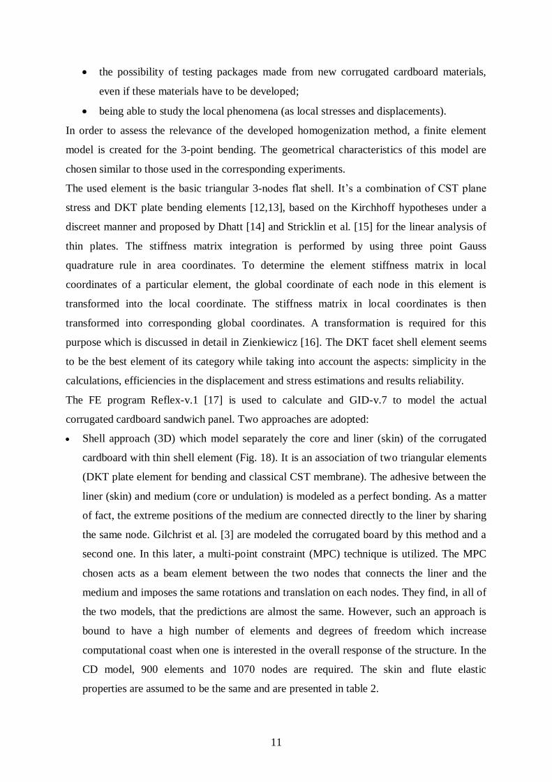
The corrugated cardboard is an orthotropic sandwich with the surface plies (facing) providing
bending stiffness, separated by a lightweight corrugated core (fluting) that provides shear
stiffness. The core and facing plates are glued along the edges of the facing plates to form a
wide sandwich panel. Two main dirctions characterise this material. The first noted MD
(machine direction) corresponds to the direction of manufacturing of the material. It coincides
with the x axis. The second noted CD (cross direction) corresponds to the transverse direction
and coincides with the y axis (Fig.1).
The cardboard is manufactured by SMURFIT company and is made from chemical Kraft
fibres. The geometric material characteristics are presented in table 1.
Preparation of specimens is conducted for whole of tests, according to the recommendations
of French norms NFQ 03-002 and NFQ 03-029.
Tensile tests
The used specimens are receptively inspired from ISO type NF T51-034 and NF Q03-002 on
the mechanical characterization of plastic materials, paper and cardboard (Fig.2). Each
specimen is instrumented by a bi-directional strain gage. The most important difficulty of the
tensile tests on the corrugated cardboard resides in the bruising of the specimen heads at the
griping time.
To increase the rigidity of the specimen heads, a polyester resin is injected between flutings
and the cardboard skins to fill the existing emptiness. A particular precaution is taken at the
time of the specimen preparation in the CD. As a matter of fact, the resin risks to flow in the
useful part and distort the test.
With regard to the skins preparation, the specimen extremities are rigidified by impregnating
in the resin. This technique allows consequently to avoid the recourse to the special bits
recommended by the norm NF Q03-002. All specimens are conditioned at 23°C and 50% RH
for at least 24 h before testing. The tests are conducted under 3 mm/min cross head speed
using a sensitive load cell of 500 N.

4
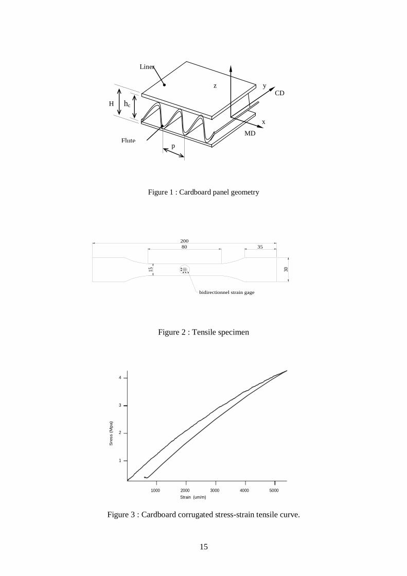
A representative example of the normal stress-strain curve of the corrugated cardboard is
pointed out in figure 3. This curve exhibits a linear part following by a non-linear one. The
later seems to be governed by a damage phenomenon which is mainly localized on the skins.
This phenomenon is more obvious in load-displacement curves of skin notably in the
transverse direction of cellulose fibers (CD). It characterizes by small load falls (Fig. 3b). The
obtained results under tensile tests are presented in table 2. It is important to note that the
result dispersion remains acceptable with a maximum value of 15.47% for ECD.. The
mechanical properties are more important in the MD than CD. One can conclude that these
results are in an appropriate accordance with those results presented in the literature [2, 4, 5].
Shear tests
The shearing tests represents a suitable manner to determine the two equivalent moduli of the
transverse shearing: Gxz and Gyz. Such tests are carried out according to ASTM 273-61. The
following limits, relative to the geometry of test-tubes are to respect hc <b/2 and hcs <l/12
[1, 6] where hc is the core thickness of the sandwich and b and l are respectively the width
and the length of the specimen. The specimen is glued to loading blocks with a two-
component epoxy glue (araldite) that cures 24 hours at room temperature (Fig.5). Then, it is
conditioned at 23°C and 50% RH for 24h. As far as the loading measurement is concerned a
load cell of 20 000 N load capacity is used.
The shear moduli are determined according to the ASTM C273-61 recommendation. The
corresponding effective shear moduli in MD and CD are defined as follows :
lb
HG
iz
iz
iz
i = x,y
iz : shear stress
iz : shear strain
: slope of the linear part of the load-displacement curve
H : total sandwich thickness
b : specimen width
l : length of the specimen
The in-plane shear moduli of the skin and the corrugated are calculated using Baum’s
approximation [7] as follows

5
yx
B
xy EEG 387.0
The measured values obtained from these tests are summarized in table 3. The dispersion
concerning the out-plane shear remains acceptable (lower than 10%).
Let's analyze the load evolution during the displacement for this test. In the case of MD, this
evolution can be described by four phases before the failure (Fig. 6). The first stage is
characterized by a linear shape (elastic phase). A first load fall is observed at the end of this
stage corresponding to the downfall of flutings under shearing effect. Once the minimal
fluting thickness reaches, the material enters in the third stage during which the load increases
again. In this phase, the shear loading of fluting-skins interfaces takes place. The fourth stage
represents a total damaging of the material. The glue of starch gives up and provokes the
detachment of skins. With regard to the CD behavior, this later is characterized by an linear
elastic phase before reaching the failure as the detachment of flutings (Fig. 7).
Bending tests
The specimens of the 3-points bending tests do not require any particular preparation. Their
dimensions are 200 x 60 x 4.01 mm. The span value is 160 mm giving the span-to-thickness
ratio (L/h) equal to 39 minimizing therefore the shearing effect. The specimens are
conditioned at 23°C and 50% RH for at least 24h.
Beam deflection is measured by an LVDT transducer attached directly to the specimen. The
overall capacity of this transducer is 50 mm and the load is measured by a sensitive load cell
of 50 N. The employed cross head speed is 2 mm/min.
The figure 8 presents a typical example of load-displacement in MD. Position and diameter of
the load nose have a significant influence on the maximal value of the downfall load.
However, the elastic behavior is practically the same under these experimental conditions.
Hence, in the case of 10 mm load nose diameter positioned between two tops of undulation
(case 1), the downfall load is less important and the loss of linearity is more pronounced in
comparison with the case where the load nose is applied on the top of the undulation (case 2).
This phenomenon can be explained by the apparition of a local distortion under the load noses
on the superior skin. It is important to note that such distortion is less important in the second
case. In order to minimize this phenomenon and to avoid the localization of the load in a
particular point, other tests are carried out using 40 mm load nose diameter. The obtained
results indicate an increase of the downfall load whereas the elasticity remains unchanged.

6
The bending moduli presented in table 4 are obtained from the slope of the linear part of the
load-displacement curve by using this relation :
3
3
4 Hb
lE
where
: slope of the load displacement curve
l : length between supports
b : width of the specimen
H : thickness of the specimen
The bending moduli are considerably close to the tensile moduli giving us a certain legitimacy
to validate the tensile experimental procedure established for this material.
Formulation of the analytical model
To analyze the elastic behavior of the corrugated cardboard, the proposed technique is a point-
wise lamination approach using the classical laminate theory. This approach is inspired from
Ishikawa et al [8], Aboura [9, 10] and Scida et al. [11] related to the elastic behavior modeling
of woven composites materials.
A unit cell representative of the corrugated cardboard is defined as in figure 9 and considered
fthe skins and the undulated fluting as an assembling of many infinitesimal elements dx of
unidirectional lamina oriented at different angles.
The classical laminate theory is then applied to each element. The relationship between the in-
plane stress and moment resultants Ni and Mi , and in-plane strains, curvature j and j is
given by :
j
j
ijij
ijij
i
i
kDB
BA
M
N (i,j =1,2 and 6) (1)
in which Aij, Bij and Dij are the in-plane stiffness for each infinitesimal element dx. These are
defined by
2:
2/
2 ),,1(),,(
h
h
ij dzQzzDBA (2)

7
in which
xy
yxxy
y
yxxy
xyx
yxxy
yxy
yxxy
x
ij
G
EE
EE
Q
00
011
011
(i,j = 1,2,6) (3)
Qij is evaluated for each constituent of the corrugated cardboard unit cell. This means that the
superior and inferior skins and the fluting undulation are taken into account. The local
stiffness of each infinitesimal element depends on the constituent elastic properties as well as
on the fluting orientation defined by the local off-axis angle (x). This angle is calculated
from the fluting median fiber function Ht(x) :
))(
(tan)( 1
dx
xdHtx (4)
Ht(x) is assumed to be of sinusoidal form with a maximum thickness of hc :
)2(sin2
)(P
xhcxHt (5)
The existence of these angles leads to a reduction in the effective elastic moduli in x and y
direction. Thus, the elastic constants for the fluting can be calculated as follows.
12
4422
121
12
21
22
1221
44
1
12
2
422
1
12
121
4
2
422
1
12
121
4
)(14222/1)(
111)()()(
21/1)(
21/1)(
G
mffm
GEEEG
fmGEE
fmE
E
E
mfm
EGE
fE
E
ffm
EGE
mE
xy
xxy
y
x
(6)

8
m=cos(), f =sin(), E1, E2, 12 and G12 are the elastic properties of the fluting and skins in the
orthotropic plane.
Once the Qij terms are calculated, the in-plane stiffness coefficients can be evaluated for each
element in different regions of the unit cell by using equation (2).
The global matrices Aglobal, Bglobal and Dglobal for the corrugated cardboard unit cell are
calculated numerically from the local matrices A, B and D evaluated for each infinitesimal
element with an average in the x direction by
P
globale dxxDxBxAP
DBA0
)(),(),(1
),,( (7)
From the global matrices [A], [B] and [D], the effective Young’s moduli, shear modulus and
Poisson’s ratio of the corrugated cardboard can be obtained as
*
66
*
22
*
12
*
11
2*
12*
22
*
22
2*
12*
11
)(
)(
AG
A
A
A
AAE
A
AAE
xy
xy
Y
x
(8)
Where [A*] = [A]/H, H is the total unit cell thickness.
The relation (8) remains valid only in the case of symmetric laminate, that means that the
global matrix [B] is equal zero. The solution convergence depends on the integration step dx.
Table 5 presents the global matrix [B] evolution of for three integration steps dx : 0.1mm,
0.005 mm and 0.0005 mm. One notes that from the second step of integration, the global
matrix [B] approaches to zero. Therefore, the step integration dx equal to 0.005 mm will be
used for the model validation.
Model validation
In order to validate the analytical model, its predictions are compared with experimental
results. The geometrical parameters of the unit cell are already summarized in Table 1. By
using the mechanical properties of the skins and the fluting experimentally identified (Tab. 2
9
and 3), the predicted values compared with the experimental results are obviously
demonstrated in Table 6.
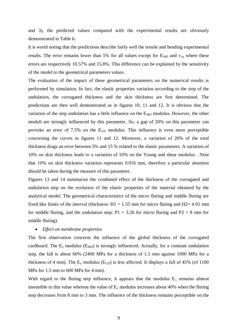
It is worth noting that the predictions describe fairly well the tensile and bending experimental
results. The error remains lower than 5% for all values except for EMD and xy where these
errors are respectively 10.57% and 15.8%. This difference can be explained by the sensitivity
of the model to the geometrical parameters values.
The evaluation of the impact of these geometrical parameters on the numerical results is
performed by simulation. In fact, the elastic properties variation according to the step of the
undulation, the corrugated thickness and the skin thickness are first determined. The
predictions are then well demonstrated as in figures 10, 11 and 12. It is obvious that the
variation of the step undulation has a little influence on the EMD modulus. However, the other
moduli are strongly influenced by this parameter. So, a gap of 20% on this parameter can
provoke an error of 7.5% on the ECD modulus. This influence is even more perceptible
concerning the curves in figures 11 and 12. Moreover, a variation of 20% of the total
thickness drags an error between 5% and 15 % related to the elastic parameters. A variation of
10% on skin thickness leads to a variation of 10% on the Young and shear modulus . Note
that 10% on skin thickness variation represents 0.016 mm, therefore a particular attention
should be taken during the measure of this parameter.
Figures 13 and 14 summarize the combined effect of the thickness of the corrugated and
undulation step on the evolution of the elastic properties of the material obtained by the
analytical model. The geometrical characteristics of the micro fluting and middle fluting are
fixed like limits of the interval (thickness: H1 = 1.55 mm for micro fluting and H2= 4.01 mm
for middle fluting, and the undulation step: P1 = 3.26 for micro fluting and P2 = 8 mm for
middle fluting).
Effect on membrane properties
The first observation concerns the influence of the global thickness of the corrugated
cardboard. The Ex modulus (EMD) is strongly influenced. Actually, for a constant undulation
step, the fall is about 60% (2400 MPa for a thickness of 1.5 mm against 1000 MPa for a
thickness of 4 mm). The Ey modulus (ECD) is less affected. It displays a fall of 45% (of 1100
MPa for 1.5 mm to 600 MPa for 4 mm).
With regard to the fluting step influence, it appears that the modulus Ex remains almost
insensible to this value whereas the value of Ey modulus increases about 40% when the fluting
step decreases from 8 mm to 3 mm. The influence of the thickness remains perceptible on the

10
in-plane shear modulus Gxy. An increase of 62.5 % of the thickness induces a decrease about
50% of the Gxy modulus.
The effect of the fluting step is more important for the strong thickness (4 mm). The modulus
Gxy value decreases by 25 % when the step evolves from 3 mm to 8 mm. Whereas, this fall is
only 6% for 1.5 mm thickness situation.
Effect on bending properties
The bending rigidities are more sensitive to the thickness than the membrane properties
(Figures 16 and 17). Thus, whatever the undulation step, the fall of the bending rigidities D11
and D22 is practically 90 % when the thickness varies from 4 mm to 1.5 mm. On the other
hand, as for the elastic modulus Ex, the bending rigidity D11 remains insensible to the step
undulation except for 4 mm thickness. Indeed, a fall of 15% is calculated when the step
undulation increase from 3 to 5 mm followed by a constants values until a step of 8 mm.
The bending rigidity in cross direction exhibits an other behaviour. In fact, the influence of
the step undulation is important for 4 mm thickness. The D22 fall by 56 % when the fluting
step increases from 3 mm to 8 mm. This influence remains perceptible for higher thickness (4
mm to 3 mm). However the CD bending rigidity, for the lower thickness, are not influenced
by the step undulation.
This parametric study shows an antagonist evolution of membrane and bending rigidities
versus total thickness. Nevertheless, the fluting step affect the Ey and Gxy more than the other
parameters. The highest values are obtained for the lowest step undulation. Thus, the choice
of geometrical parameters for optimal elastic parameters depends on the nature of loading.
For a complex loading, a compromise between membrane and bending rigidities is necessary.
This analytical model seems to be an interesting tool for making decision regarding the
geometrical parameters choice for an optimum elastic solution.
Finite element analysis
The main advantages of the mechanical behavior simulating of corrugated cardboard product
are:
decreased development costs, since less experiments are necessary in the process
development phase;
a faster development phase, since more information on the mechanical properties of a
corrugated cardboard is obtained in an early stage of its design;
11
the possibility of testing packages made from new corrugated cardboard materials,
even if these materials have to be developed;
being able to study the local phenomena (as local stresses and displacements).
In order to assess the relevance of the developed homogenization method, a finite element
model is created for the 3-point bending. The geometrical characteristics of this model are
chosen similar to those used in the corresponding experiments.
The used element is the basic triangular 3-nodes flat shell. It’s a combination of CST plane
stress and DKT plate bending elements [12,13], based on the Kirchhoff hypotheses under a
discreet manner and proposed by Dhatt [14] and Stricklin et al. [15] for the linear analysis of
thin plates. The stiffness matrix integration is performed by using three point Gauss
quadrature rule in area coordinates. To determine the element stiffness matrix in local
coordinates of a particular element, the global coordinate of each node in this element is
transformed into the local coordinate. The stiffness matrix in local coordinates is then
transformed into corresponding global coordinates. A transformation is required for this
purpose which is discussed in detail in Zienkiewicz [16]. The DKT facet shell element seems
to be the best element of its category while taking into account the aspects: simplicity in the
calculations, efficiencies in the displacement and stress estimations and results reliability.
The FE program Reflex-v.1 [17] is used to calculate and GID-v.7 to model the actual
corrugated cardboard sandwich panel. Two approaches are adopted:
Shell approach (3D) which model separately the core and liner (skin) of the corrugated
cardboard with thin shell element (Fig. 18). It is an association of two triangular elements
(DKT plate element for bending and classical CST membrane). The adhesive between the
liner (skin) and medium (core or undulation) is modeled as a perfect bonding. As a matter
of fact, the extreme positions of the medium are connected directly to the liner by sharing
the same node. Gilchrist et al. [3] are modeled the corrugated board by this method and a
second one. In this later, a multi-point constraint (MPC) technique is utilized. The MPC
chosen acts as a beam element between the two nodes that connects the liner and the
medium and imposes the same rotations and translation on each nodes. They find, in all of
the two models, that the predictions are almost the same. However, such an approach is
bound to have a high number of elements and degrees of freedom which increase
computational coast when one is interested in the overall response of the structure. In the
CD model, 900 elements and 1070 nodes are required. The skin and flute elastic
properties are assumed to be the same and are presented in table 2.

12
Plate approach (2D) considers the corrugated cardboard sandwich as a homogeneous plate
and is modeled therefore by a triangular 3-node DKT plate element. For this model, the
effect of the mesh refining on the solution convergence is investigated. Thus, 80, 160 and
240 elements are used. The elastic properties introduced in the FE analysis are those
obtained by the analytical model and presented in table 6.
First, let's analyze the effect of the number of elements on the 2D model. Refining the mesh
has not a significant influence on the result accuracy (Table. 7). For this reason, the 2D model
with 160 elements is considered for analysis after mesh convergent studies.
Table 8 presents a comparison between experimental and the two FE approaches results. The
calculation times (CPU) of personnel computer with AMD Duron 850 MHz processor are also
indicated for the two approaches. The ratio FE / experiment for the 3D approach is 1.07.
These same ratios are 1.08 and 0.88 respectively for MD and CD for the simplified
homogenization procedure. The correlation between experimental and the two FE approaches
is correct. However, for an overall behavior, the time calculation of the 2D approach is 10
time lower than that of the 3D approach. It appears that the simplified homogenization
procedure is adequately accurate and fast for effectively analyzing corrugated cardboard panel
in the preliminary and optimization design stages.
Conclusions
Although the corrugated cardboard has a constitution of a sandwich structure, its structural
properties are revealed once the packing structure is constituted. This fact leads to consider
that this sandwich is like a monolithic material. Hence, an experimental protocol is developed
to determine its 2D orthotropic stiffness matrix.
As far as the modeling is concerned, an analytical model, taking into account the geometrical
and mechanical properties of the cardboard constituents, is also proposed to predict these in-
plane properties. This model is also able to predict the bending properties.
After the model validation showing a good correlation between experimental and analytical
results, a parametric study is conducted. This allows to analyze the effect of geometrical
parameters on in-plane elastic properties. Thus, it appears that the EMD modulus and bending
properties (D11 and D22) are strongly influenced by the total thickness of the corrugated
whereas the ECD modulus is more affected by fluting step. The proposed model should be an
interesting tool for a help to decision on the choice of geometrical parameters for an optimum
elastic solution

13
In order to assess the relevance of the homogenization method developed for this purpose, a
finite element analysis is used. The main goal of this work is to verify the possibility to use a
2D meshing of the corrugated cardboard, in stead of of a 3D meshing extensively used in the
literature. It was found that the simplified homogenization procedure is adequately accurate
and fast for effectively analyzing corrugated cardboard panel in the preliminary and optimum
design stages.
References
1 Nordstrand T.M. and Carlsson L.A, Evaluation of transverse shear stiffness of
structural core sandwich plates Composite structures 1997, 37,145-153.
2 Patel P, Nordstrand T.M, and Carlsson L.A, Local buckling and collapse of
corrugated cardboard under biaxial stress Composite structures 1997, 39, 93-110.
3 Gilchrist A.C, Suhling J.C and Urbanik T.J, Nonlinear finite element modeling of
corrugated cardboard Mech.of Cellulosic Mat. 1999, 85, 101-107.
4 Nordstrand T.M, Parametric study of the post-buckling strength of structural core
sandwich panels Composite structures 1995, 30, 441-451
5 El Damatty A.A.,. Mikhael A and Awad A.A, Finite element modelling and
analysis of a cardcardboard shelter Thin-Walled Structures 2000, 38, 145-165.
6 Desrumaux F. Contribution à l’analyse micromécanique du comportement élastique
en dommageable de composites monolithiques et sandwichs, intégration dans un
code de calculs par éléments finis Thèse de doctorat Université de technologie de
Compiègne 2000.
7 Baum G.A., Brennan D.C. and Haberger C.C. Orthotropic elastic constants of paper
TAPPI J 1981, 64, 97-101
8 Ishikawa T, Chou TW. Stiffness and strength behavior of woven fabric composites.
Jour. of Mat. Sci.. 1982, 17, 3211-3220.
9 Aboura, Z., Etude du processus de délaminage Mode I, Mode II et Mode mixte (I et
II) de matériaux composites à renforts tissés à différentes vitesses de sollicitation,
Thèse de Doctorat, Université de Technologie de Compiègne 1993.
10 Aboura, Z., Chouchaoui, C.S. and Benzeggagh, M.L., Analytical model of woven
composite laminate. Superposition effect of two plies, ECCM 6, 1993, Bordeaux.

14
11 Scida, D., Aboura, Z., Benzeggagh, M.L. and Bocherens, E., Prediction of elastic
behaviour of hybrid and non-hybrid woven composite, Composites, science and
technology. 1997, 57, 1727-1740
12 Batoz J.L, Bath K.J,.and Ho L.W, A Search for the Optimum Three-Node Triangular
Plate Bending Element. Rapport 82448-8, Massachusetts Institute of Technology,
December 1978.
13 Batoz J.L, Bath K.J,.and Ho L.W, A study of Three-Node Triangular Plate Bending
Elements, Int. J. Num. Meth. In Eng.,. 15, 1771-1812,.
14 Dhatt G., Numerical Analysis of Thin Shells by Curved Triangular Elements Based on
Discrete Kirchhoff Hypothesis, Proc. ASCE Symp. On Applications of FEM in Civil
Engineering, Vanderbit University, Nashville, Tenn. Nov. 1969, 13-14.
15 Stricklin J.A., Haisler W., Tisdale P. and Gunderson R., A rapidly Converging
Triangular Plate Element, AIAA J1969., 7, 180-181.
16 .Zienkiewicz O.C. and Taylo r R.L, The Finite Element Method, 4th
Ed. McGraw-Hill,
New York, 1991.
17 Batoz J.L and Dhatt G, Modélisation des structures par éléments finis, Volume 1:
Solides élastiques. Hermèse Edition 1992
15
Figure 1 : Cardboard panel geometry
200
3580
15 30
bidirectionnel strain gage
Figure 2 : Tensile specimen
4
3
2
1
Sre
ss (
Mp
a)
5000 4000 3000 2000 1000
Strain (um/m)
Figure 3 : Cardboard corrugated stress-strain tensile curve.
z y CD
MD
x
p
H hc
Flute
Liner

16
140
120
100
80
60
40
Load (
N)
7 6 5 4 3 2 1 0 Displacement (mm)
CD direction
MD direction
Figure 4 : Skin load displacement tensile curve
Action plan of the force
P
P
Test specimen
Loading platens
Figure 5 : ASTM block shear test

17
6000
5000
4000
3000
2000
1000
0
load (
N)
5 4 3 2 1 0
Displacement (mm)
Elastic phase
Fluting falls
failure
Figure 6 : MD load-displacement shear curve.
Figure 7 : CD load-displacement shear curve.
12x10 3
10
8
6
4
2
0
Load (N)
1.5 1.0 0.5 0.0 Displacement(mm)

18
10 mm
10 mm P
5
4
3
2
1
0
Load (
N)
10 8 6 4 2 0
Deflection (mm)
40 mm
P
Figure 8 : MD load-deflection curves for different load nose diameters.
P
a
b
c
d
e
.
dx
hc
V E R
dH
t
x
1
3
2
z
Hp
iH
pi
(a) superior skin
(b) emptiness
(c) fluting
(d) emptiness (e) inferior skin
Figure 9 : Unit cell representative of the corrugated cardboard

19
Figure 10 : Variation of elastic properties versus step variation.
Figure 11 : Variation of elastic properties versus skin and flute thickness variation.
0 5 10 15 20 25 30 35 40 45 50 -15
-10
-5
0
5
10
Step variation (%)
V
ariation o
f ela
stic p
ropert
ies
(%)
EMD
ECD
Nuxy
Gxy
0 5 10 15 20 25 30 35 40 45 50 0
5
10
15
20
25
30
35
40
45
50
Variation of skin and flute thickness (%)
V
ariation o
f ela
stic p
ropert
ies (
%)
EMD ECD
Nuxy
Gxy

20
Figure 12 : Variation of elastic properties versus total thickness variation.
Figure 13 : Evolution of EMD versus thickness and flute step
0 5 10 15 20 25 30 35 40 45 50 -35
-30
-25
-20
-15
-10
-5
0
Variation of the total thickness (%)
V
ariation o
f ela
stic p
ropert
ies
(%)
EMD
ECD
Nuxy
Gxy
Total thickness (mm)
EMD
(Mpa)
Flut step (mm)

21
Figure 14 : Evolution of ECD versus thickness and flute step
ECD
(MPa)
Total thickness (mm) Flute step (mm)

22
Figure 15 : Evolution of Gxy versus thickness and flute step
Figure 16 : Evolution of bending rigidity D11(MD)versus thickness and flute step
GXY
(MPa)
Total thickness (mm) Flute step (mm)
D11 (Nmm)
Total thickness (mm) Flute step (mm)

23
Figure 17 : Evolution of bending rigidity D22 (CD) versus thickness and flute step
Figure 18 : 3D and 2D finite elements meshing.
D22 (Nmm)
Total thickness (mm) Flute step (mm)

24
Thickness(mm) Flute step (mm) Liner thickness (mm) Nbre of flute by meter
4.01 8 0.16 125
Table 1 : Geometrical parameters
Table 2 : Tensile properties of skins and cardboard corrugated.
Gxz Corrugated
(Mpa)
Gyz Corrugated
(Mpa)
B
xyG Skins
(Mpa)
B
xyG Corrugated
(Mpa)
2.32 0.12 3.926 0.14 2052.76 267.83
Table 3 : Shear properties of cardboard corrugated and skins
EMD (MPa) ECD (MPa) EMDflex/EMDtensile ECDflex/ECDtensile
844.4571.29 605.7324.54 0.97 1.09
Table 4 : Bending properties.
dx (mm) 0.1 0.005 0.0005
[B]
211.000
0620.27738.0
0773.0543.1
5.000
06.69.1
09.19.3
10 3
052.000
0663.0193.0
0193.0387.0
10 4
Table 5 : Influence of the step integration dx on the global matrix [B]
EMD (Mpa) xy MD (Mpa) ECD (Mpa) yx CD (Mpa)
Skins 8258.53744.03 0.390.061 50.071.60 3406.84258.4 0.140.01 23.510.71
Corrugated
863.0599.50 0.270.03 4.440.14 554.9785.89 0.220.03 2.7600.28

25
Analytical results Experimental
results
(Anal.-Exp) /Exp.
EMD (MPa) 954.34 863.05 10.57%
ECD (MPa) 552.02 554.97 -0.53%
xy 0.314 0.271 15.8%
Gxy (MPa) 274.58 267.834* 2.51%
D11 (N.mm) 4347.6 4537.6 -4.1%
D22(N.mm) 3104 3254.84 -4.6%
* Obtained by Baum’s relation
Table 6 : Comparison between analytical and experimental results
N x M 2 x 10 4 x 20 6 x 30
d.o.f 99 315 651
MD deflection (mm) 1.3479 1.3563 1.3562
CD deflection (mm) 2.4650 2.4788 2.4787
Table 7- Convergent studies
Plate FE
MD
Plate FE
CD
Shell FE
CD
Exper.
CD
Exper.
MD
Bending rigidity
(N/mm)
3.68 2.017 2.47 2,290,09 3.390.36
CPU Time (s) 0.3 0.3 3 / / Total load is 5 N.
Table 8 : Comparison between FE and experimental results

26