EL ECTRl I - NASA · EL ECTRl ChL A AUBURN RESEARCH FOUNDATL AUBURN UNIVERSITY AUBURN, ALABAMA ......
77
I ’ I I I ‘. I . > I, , - < 1. (PASES) &? 7uoof + (NASA CR OR TMk OR AD NUMBER) EL ECTRl ChL A AUBURN RESEARCH FOUNDATL AUBURN UNIVERSITY AUBURN, ALABAMA https://ntrs.nasa.gov/search.jsp?R=19660015196 2018-11-10T00:02:41+00:00Z
Transcript of EL ECTRl I - NASA · EL ECTRl ChL A AUBURN RESEARCH FOUNDATL AUBURN UNIVERSITY AUBURN, ALABAMA ......

I ’ I I I
‘ .
I
.
> I , , - < 1.
(PASES)
&? 7uoof + (NASA CR OR TMk OR AD NUMBER)
EL ECTRl ChL A
AUBURN RESEARCH FOUNDATL
AUBURN UNIVERSITY AUBURN, ALABAMA
https://ntrs.nasa.gov/search.jsp?R=19660015196 2018-11-10T00:02:41+00:00Z

TECHNICAL REPORT MIMBER 5
A VHF DIRECTION FINDING SYSTEM
P r e p a r e d by
ANTENNA RESEARCH LABORATORY
E. R. GRAF, PROJECT LEADER
January 19, 1 9 6 6
CONTRACT NAS8 - 1 12 5 1
GEORGE C. MARSHAL, SPACE FLIGHT C E h T R
NATIONAL AERONAUTICS AND SPACE ADMINISTRATION
HUNTSVILLE, ALABAMA
APPROVED BY
C. H. H o l m e s Head Professor E l e c t r i c a l E n g i n e e r i n g
SUBMITTED BY
H. M. Surmner Professor of E l e c t r i c a l E n g i n e e r i n g

FOREWORD
This is a special technical report on a study conducted by the
Electrical Engineering Department under the auspices of the Auburn
Research Foundation toward the fulfillment of the requirements
prescribed in NASA Contract NAS8-11251.
finding system for use at VHF frequencies is presented.
An electronic direction
ii

TABLE OF CONTENTS
LIST OF F I G U R E S ............................................... iv
I . INTRODUCTION ............................................ I1 . THEORETICAL D I S C U S S I O N ..................................
I11 . CONCLUSIONS ............................................. APPENDIX A ....................................................
1
3
32
33
APPENDIX B .................................................... 7 1
iii

L
LIST OF FIGURES
1. The Coordinate System ..................................... 4
2 . A Four Element Array of Isotropic Antennas................ 5
3. The Direction Finding Antenna and Its Image ............... 16
4. Half-Wave Dipole Pattern Factor........................... 21
5. Phase Error Introduced by Interfering Signal .............. 27
6. Horizontal and Vertical Image Array Factors, h = X / 4 ...... 28
7. Null Angles as a Function of Antenna Height Above a Perfectly Conducting Ground Plane for Both 0 and @ Polarization..........................o............... 29
30
31
8 .
9 .
Photograph of the Direction Finding Antenna Prototype ..... Block Diagram of the VHF Direction Finding System .........
A-1 to A-37. Directional Characteristics of the Received Signal .......................................... 34-70
iv

I INTRODUCTION
H. P. Neff, R. J. Coleman and E. R. Graf
A need exists for a direction finding device to be used at VHF
frequencies. Conventional direction finders employ such devices as
loop antennas. These loops are rotated until a null in the antenna
pattern is aligned with the signal direction. This method requires
a mechanical rotation of the antenna which may be a disadvantage if
the system is to be used in an unmanned application. A receiving
antenna with a very narrow beamwidth may be used as a direction
finder with the direction information being taken again fromthe
pointing of the antenna. This also requires mechanical movement of
the antenna and presents the problem of forming narrow beams at
VHF frequencies. This method requires large physical structures for
the antenna.
The direction of an incoming signal may be obtained from an
appropriate antenna array.
of four elements arranged in a square. The elements are each composed
of two orthogonal dipoles. This particular configuration is necessary
since the antenna must respond to a signal of any polarization through-
out a hemisphere of coverage.
of four vertical dipoles and a similar array of horizontal dipoles.
The array under consideration consists
The array may be thought of as an array
1

2
In t h i s configurat ion the d i rec t ion information may be extracted from
the antennas which respond t o vertical polar iza t ion with no coupled
s i g n a l due t o the a r ray which i s affected by horizontal polar izat ion.
The a r r ay allows the ex t rac t ion of d i rec t ion information i n the
form of a d i r ec t ion cosine analog.
by the e lec t ronic equipment which follows the antenna array.
Information i n t h i s form is usable
A matrix system of phase l ines and associated equipment follow
the antenna array.
t i o n a l t o d i r ec t ion cosine analogs and a reference s igna l t o be
This allows voltages with phase angles propor-
obtained from the array. Conventional phase measuring equipment may
be used on a s igna l of t h i s type to obtain the d i r ec t ion of the re-
ceived s igna l .

11. THEORETICAL D I S C U S S I O N
A plane wave from some point in space will exhibit in general
both 8 and 4 polarization.
must be capable of receiving both types of polarization. It would be
highly desirable for the antenna to possess a hemispherical radiation
characteristic for both types of polarization.
demonstrated that this requirement cannot be completely satisfied in
practice.
Therefore a direction finding antenna
It will later be
In order to demonstrate the basic principles of the direc-
tion finding system, first consider a four element array of identical
sources as shown in Figure 2.
It is helpful in determining the performance of an antenna as
a receiving antenna to determine first its performance as a trans-
mitting antenna and then invoke reciprocity.
field of an antenna is composed of two parts in general,
The far-zone radiation
and
3

4
I I I I I I I I I I I
I I I I I I
Fig. 1--The coordinate system.

5
X
Fig. 2--A four element array of isotropic antennas.

6
1 sin@ + A cos0 Y
The receiving characteristics of an array will depend on the
polarization of the received signal as shown in equations (1) and
(2), and also on the magnetic vector potential components A A x' Y
For the hypothetical radiators a system of simultaneous equations
and AZ.
describing the behavior of the array may be written:
jkacos0, V1 = f1(8,@)e = '1'11 + '2'12 '3'13 '4'12
- j kacose, V3 = fg(B,@)e = '1'13 '2'12 + '3'11 + '4'12
In these equations Z is the self impedance of each element plus the
input impedance to the connected transmission line, Z12 is the mutual
impedance between one element and its nearest adjacent antenna, and
Z13 is the mutual impedance between one element and the element dia-
metrically opposite.
11
It is extremely important to recognize that these

7
equations hold i f , and only i f , each element of t he four element a r r ay
i s i n the same environment a s each of t h e other elements. This con-
d i t i o n i s s a t i s f i e d i f , given f1(0,@),
f2(e ,@) = f l (e ,@ + d 2 )
With these requirements es tabl ished and given the dimensions of
the S-band t racking antenna and the equations governing i t s beam
point ing the following equations apply:
-a 6o cose, = s i n 8 cos Cb = -
kd
-mE0 cos eY = s i n 8 s i n Cb = - kd
where
and d i s t h e element spacing i n the S-band array.
Therefore ,

ka cos e, = - - a aso = - ca d
a = - - m6, = - c m ~ Y d
ka cos e
where
8
a60 0.25h (22.50), e=--- d - 0.44A
The integers ,P, and m are the quantities which actually determine
For each integral step in ,P, the beam pointing of the S-band antenna.
the diode phase shifters introduce an additional phase shift of ho=22.5O
in the x direction.
additional phase shift of 6, = 2 2 0 5 ~ in the y direction.
each possible combination of ,!, and m the beam will co-phase in a
different direction in space.
Likewise each integral step in m introduces an
Thus,for
The possible values of j,m are
< = \!$I = 7.04.
0
The same considerations hold for mwith cos 8, replaced by cos eY
Thus, the values are,

9
- 754,m L + 7 .
By use of equations (8) and ( 9 ) , the system equation (3), may
be simplified as follows:
= '1'11 -I- '2'12 + '3'13 i- '4'12 V1 = fle -j c4
j c& I
V3 = f3e = '1'13 '2'12 -t '3'11 '4'12
j cm v4 = f4e = 11Z12 + I2ZI3 + 13Z12 + 14Zll .
The equations (12) reveal the quantities which the
direction finding system must measure. That is, ,!, and m, appear as
phase angles (with a scale factor c) on the antenna terminal voltages.
Any scheme for measuring these phase angles (and hence 4 and m) at
this point must account for the mutual impedance. This antenna is
actually a four element circular array, and it is well known that if
each element is identical, then the system equations may be uncoupled.
The scheme for accomplishing this depends on forming the sequence
(0) (1) (2) (3 1 voltages VR , VR , VR , and VR e In this notation the super-
script indicates the sequence number.
The zero sequence, VR(0), is formed by summing all the terminal
voltages across a common load, R, through equal length transmission
lines. This would lead to the following equations.

10
VR(0) = [I1 + I2 + I3 + 14 R, and 1
This se t of equations may be solved t o y i e ld
The zero sequence impedance, Z'O), i s defined as:
Accordingly, V i o ) may be w r i t t e n as
The sequence voltage, Vi'), i s formed by combining the antenna
vol tcge VI, t he aqtenna voltage V2 through a 3X/4 l i ne , t he antenna
vol tage Vg through a X/2 l i n e and t h e antenna voltage VL through a
X I 4 l ine . This g ives

Simi lar i ly , the expression for Vi2) and vR(3) a r e
VR(2) = V1 - V2 + V3 - V4, and
vR(3) = v1 - jv2 - v3 + j v 4‘
When the indicated operations are performed, it follows tha t
where

12
Thus, bv using phased transmission lines and simple passive com-
biners it is possible to form the sequence.voltages and uncouple
the system equations. There is one step remaining before the
sequence voltages may be utilized to obtain j and m.
of the sequence impedance in each of the sequence voltages makes the
coefficient, vR e-j@n unequal for n = 0,1,2 and 3. This diffi-
The presence
i Z(n) I I I
culty may be removed by a simple normalization process.
requires the use of an attenuator for each sequence voltage to equalize
the amplitudes, and a phase shift (additional line length) to equalize
the phases, On.
the attenuation introduced will be small in general, it was felt
attenuators would cause less difficulty than amplifiers in practice.
This process
The use of an attenuator is not desirable, but since
The normalized sequence voltages may now be written:

13
The voltages f o r determining J and m a r e now formed i n a manner
s i m i l a r t o t ha t used i n forming the sequence voltages, t ha t is,
V = 4f3(9,@)ejc', and a
j cm Vm = 4f4(9,0)e .
A reference s i g n a l fo r phase measureinents is needed, and i n t h i s
case VRN (O) would serve as a reference, therefore,
The three terminal voltages a r e
V = 4f3ejca, and a
14
j cm V = 4 f e . m 4
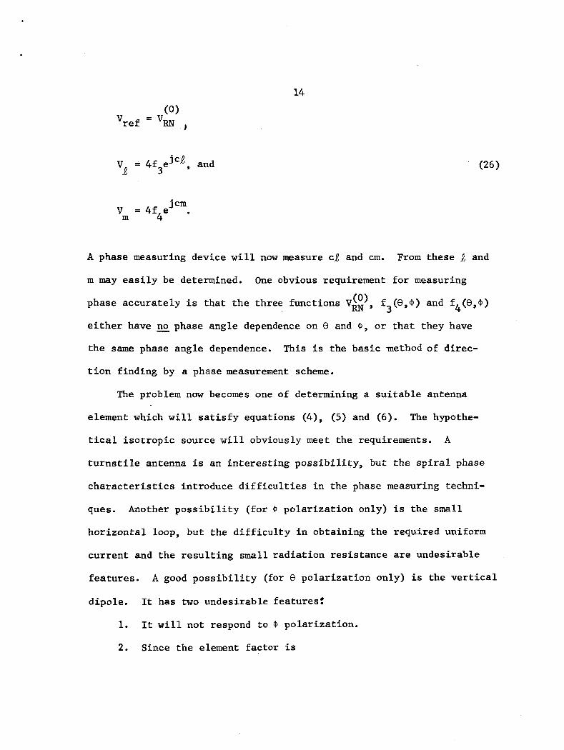
A phase measuring device will now measure ca and cm.
m may easily be determined. One obvious requirement for measuring
From these and
phase accurately is that the three functions Vm (0) , f3(8,9) and f4(8,@)
either have no phase angle dependence on 8 and @, or that they have
the same phase angle dependence.
tion finding by a phase measurement scheme.
This is the basic method of direc-
The problem now becomes one of determining a suitable antenna
element which will satisfy equations (4), (5) and (6). The hypothe-
tical isotropic source will obviously meet the requirements. A
turnstile antenna is an interesting possibility, 3ut the spiral phase
characteristics introduce difficulties in the phase measuring techni-
ques. Another possibility (for 0 polarization only) is the small
horizontal loop, but the difficulty in obtaining the required uniform
current and the resulting small radiation resistance are undesirable
features.
dipole.
1.
2. Since the element factor is
A good possibility (for 0 polarization only) is the vertical
It has two undesirable features:
It will not respond to 0 polarization.

15
i t w i l l not respond t o any polar izat ion a t 8 = 0.
The f i r s t of these def ic ienc ies may be p a r t i a l l y remedied by adding
hor izonta l elements whose phase center i s coincident with the hypo-
t h e t i c a l sources used i n the derivation. These elements must be in-
corporated i n such a way t h a t they do not i n t e r f e r e with the uncoupling
f ea tu re of the impedances upon which the phase measurement depends.
That i s t o say, equations (4), (5) and (6) must be s a t i s f i e d . Sa t i s -
fying these equations, and recognizing t h a t only Ax and A components
of vector p o t e n t i a l exist f o r horizontal elements, requi res t h a t the
f i e l d be zero along t h e polar ax i s (e = O o ) .
f i c i ency may not be overcome i n any case, and the system w i l l not
respond t o s i g n a l s from €3 = 0'.
d i f f i c u l t y as w i l l later be demonstrated.
Y
Thus, t he second de-
This is not an unsurmountable
An arrangement which appears t o incorporate the best fea tures of
t h i s type system is shown i n Figure 3.
four element a r r a y of dipoles w i t h t h e i r feed poin ts a t the same
loca t ions as those of 'the v e r t i c a l elements.
The hor izonta l p a r t i s a
The t h e o r e t i c a l performance o f such an a r r ay w i l l now be invest i -
A l l of t he previously developed equations hold symbolically, gated.
w i th the exception t h a t the angular dependence of each element
(element f ac to r ) should be examined separa te ly f o r the two types of
po lar iza t ion .

16
Fig. 3--The direction finding antenna and its image.
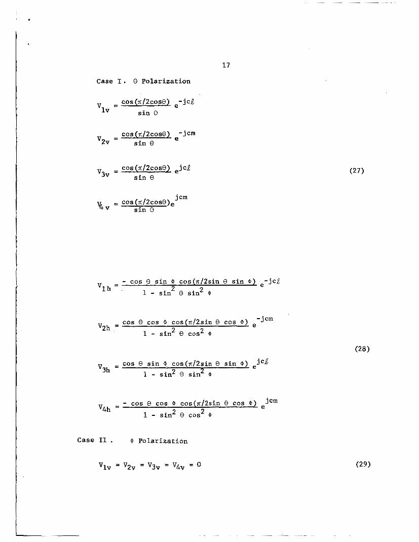
1 7
Case I . 0 Polar iza t ion
cos (sr/2cose) e- j c j v = l v s i n 8
cos (n/2cose) - j c m e - v2v - s i n 8
cos ( ~ / 2 c o s 0 ) .jca v3v = sin e
j cm - COS ( T ~ / ~ c o s O ) ~ - v4 v s i n 0
- cos e s i n @ cos(sc/2sin e s i n @ ) .-jcQ 1 - s i n 2 8 s i n 2 $ ' lh = .
-jcm cos 8 cos ~b cos(n/2sin 8 cos 'P) e V2h =
1 - s in2 e cos2
- cos e s i n a, cos(x/2sin e s i n ejcQ
1 - sin2 e s in2 Q '3h -
j cm - cos e cos @ cos(x/2sin 8 cos @ ) e
1 - s in2 e cos2 @ '4h =
Case I1 . @ Polar iza t ion
Vlv = v2v = v3v = v4v = 0

18
- - cos @ cos(sr/2sin e s i n 4) .-jcR 'lh - 1 - s in2 e s i n 2 @
- s i n cos(rr/2sin 0 cos Q i e - j c m '2h =
1 - s in2 0 COS 2 4
= s i n @ cos(lr/2sin e cos a ) ejcm 4h 1 - s in2 e cos2 @
I n these equations the numbered subscr ipts r e f e r t o the element lo-
ca t ion and the l e t t e r e d subscr ipts r e f e r t o the hor izonta l or v e r t i c a l
element.
t o y ie ld the following r e su l t s .
The sequence vol tages are formed,normalized and recombined
Case I . 0 Polar iza t ion
1 cos(n/2sin e cos 0) + cos(lrf2sin e s i n a ) - 2cos (X/2COS e) - r e f ,v s i n 8 V
= 4 COS COS e) ejca
s i n 0 '1 ,v

19 1 cos e s i n 0 cos(lr/2sin e s i n @ ) s i n ( ~ / 2 s i n e cos Q)
1 - s in2 e s i n 2 0 vref ,h = 2 j
1 - cos e cos o cos(z/2sin e cos @)sinfi/2(sin e s i n O)
1 - s in2 e cos2 0
1 - - 4 cos e s i n Q cos(n/zsin e s i n Q) e j ~ J f?,h 1 - s in2 e s in2 Q
V
I -4cos e cos Q cos(n/2sin e cos @ ) jcm v = e m, h 1 - sin2 e cos2 o
Case 11. Q Polar izat ion
cos UJ cos(z/2sin e s i n @)sin(lr/2sin e cos O) 2 1 - s in2 e s i n Q
'ref,h = 2 j
+ s i n 0 cos(n/2sin e cos @)sin(lr/2sin 8 s i n @
1 - s in2 e cos2 o
4cos O cos(n/2sin 8 s in 0 ) j c j e - - 2
v a ,h 1 - s in2 e s i n o
- 4s in o cos(n/2sin e COS 0) .jcm v - m,h 1 - s in2 e cos2
These equations,less the phase factors,have been programed and
ca lcu la ted by computer i n f i v e degree increments of 8 and O for ranges

t -
i
20
of 0 t o 90 degrees i n 0 and 0 t o 180° i n @. fo r
The da ta may be extended
ranging from 0 t o 180' through negative values by taking note @
t ha t , neglect ing the phase terms
(e,@) = + v (0, - 0) (even function of 4 ) r e f ,v r e f , v V
vm,v(e,@) = + v (0, - @ I (even function of @) m, v
I
(e,@) = - v' (0, - @ ) (odd function of 0) 'ref,h r e f , h
(odd funct ion of @ ) ( 3 4 )
(even function of @ )
(0, - 0) (even function of @ ) Vref,h'e'@) = + 'ref,h
v (e,@) = + Vref ,h (0, - @ ) (even function of @ )
vm,h(e,@) = - V (6, - $) (odd fuilction of @ )
,t,h
"9 h
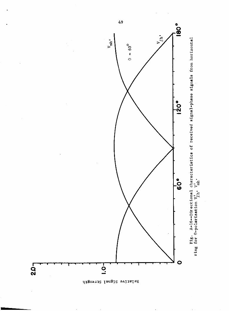
The funct ions Va and'V
are shown i n Figure 4 . The function V ' i s less than 0.02 i n
magnitude (normalized) and i s not p lo t ted . The other functions a r e
shown in Figures A-1 through A-37 .
dent va r i ab le and 0 is the parameter.
a r e t h e ordinary d ipole p a t t e r n fac tor and ,v m,v
r e f ,h
On these p l o t s @ i s the indepen-

21
I I I

22
In order to fully understand the system, one must take into
account the effects of multipath.
degradation of performance by multipath signals.
true of a direction finc’ing system in which a phase measurement de-
termines the direction of arrival of the signal.
Figure
could introduce a phase shift of thirteen degrees.
(10) it may be seen this is sufficient to cause the system to misread
Any antenna system is subject to
This is especially
An inspection of
5 shows that a multipath signal down by only thirteen db
From equation
or m by one integer, causing the beam in the S-band antenna to
point in an incorrect direction.
The most likely source of multipath signals is a reflection from
the ground surrounding the antenna. It could be anticipated that the
system would be subjected to a wide range of reflection coefficients,
depending on the exact geographical location.
tion coefficient usually lies between 0.3 and 0.7 in magnitude.
series of experimental tests were performed to determine how the
reflection coefficient could be reduced 3y placing absorbing material
under an antenna similar to the one previously described. These
tests show the reflection coefficient was reduced for some polar
angles, but nulls in the radiation patterns occured at other angles
The value of reflec-
A
which were not present without the absorbing material.
indicate when the material was used, energy was being scattered.
From the results of these tests, it was felt the only way to resolve
These tests

23
t he d i f f i c u l t y with multipath s ignals due t o ground r e f l ec t ions i n
a predic tab le manner w a s t o build the d i r ec t ion f inding system
above a meta l l ic ground plane.
r e f l e c t i o n w i l l be un i ty for a l l p rac t i ca l purposes.
I n t h i s case the coe f f i c i en t of
The use of a ground plane would o rd ina r i ly c rea t e many problems
I f a l l the v e r t i c a l elements of the array due t o the image e f f ec t s .
have phase centers i n the same horizontal plane, and a l l the hori-
zonta l elements of the a r r ay l i e in the same hor izonta l plane, then
a l l the previously developed equations are valid symbolically.
i s t o say, t he system of simultaneous equations w i l l be uncoupled
and the d e s i r e d parameters and m may be measured. Each t e r m
involving a hor izonta l element must be mult ipl ied by
That
- j 2khcos9 Fih = 1-e
t o account f o r the image array. In t h i s equation h i s the height of
t he antenna phase center above the ground plane. I n the same manner
every t e r m i n the v e r t i c a l a r r ay must be mult ipl ied by
- j 2khcos9 F = l + e
i v
t o account fo r i t s image array. ince these "image a r r ay --Lctors"
introduce t h e same phase angle var ia t ion i n t o each term, the mag-
ni tudes of these t e r m s a r e su f f i c i en t as a multiplying coef f ic ien t
f o r pa t t e rn ca lcu la t ion . This i s not t r u e i f the s igna ls from
(35)

I
24
the v e r t i c a l elements are combined with those from the hor izonta l
array. I n t h i s case the factors F and Fih must be used as they
appear above.
i v
These a r ray fac tors may be wri t ten:
- j khcose = 2jsin(khcosO) e
- jkhcose Fiv = 2cos(khcos0) e
(37)
I n order t o determine the performance of the d i r ec t ion finding
system above the ground system, equations (37) and (38) are introduced
i n t o equations (31), (32) and (33). I n addi t ion, an angle a! is in-
troduced t o d is t inguish the
po la r i za t ion ; such t h a t a! = 0 for 8 - polar iza t ion only, and a: = sr/2
f o r (0 - po la r i za t ion only.
h / 4 are:
cases of €3 - polar iza t ion and @ -
The r e su l t i ng equations f o r a height of
-i - Tc cos€+, = 4 c o ~ c o s ( ~ j 2 c o s ~ ) e - ;Z
re€ ,v V" r e f , v
j cm 3-t -j -cos@ V" = 8 c o ~ c o s ( x / 2 c o s ~ ) e 2 V e
m, V m,v
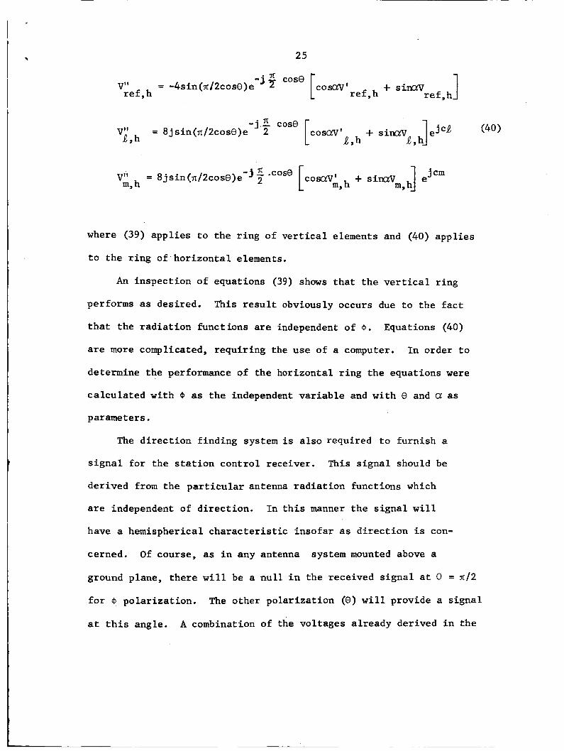
25
1 -j + case + siMuv r e f ,h r e f ,h V" = -4sin(xj2cose)e [ c o r n ' r e f , h
- j X .case V" = 8jsin(x/2cos0)e 2 m, h
where (39) appl ies t o the r ing of v e r t i c a l elements and (40) appl ies
t o the r i n g of hor izonta l elements.
An inspect ion of equations (39) shows tha t t he vertical r ing
performs as desired. This r e s u l t obviously occurs due t o the f ac t
t h a t the r ad ia t ion funct ions are independent of @. Equations (40)
are more complicated, requir ing the use of a computer. I n order t o
determine the performance of the horizontal r i ng the equations were
ca lcu la ted with @ as t h e independent var iab le and with 8 and Q! as
parameters.
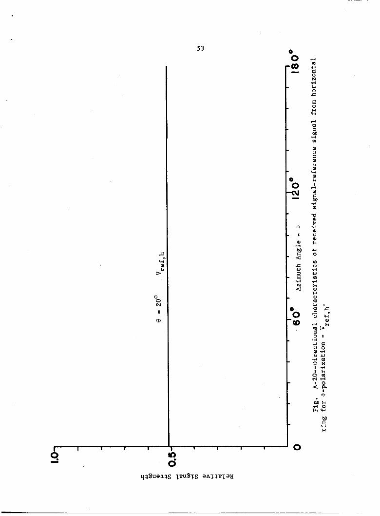
The d i r ec t ion f inding system is a l so required t o furnish a
s i g n a l for the s t a t i o n cont ro l receiver. This s igna l should be
derived from the p a r t i c u l a r antenna r ad ia t ion functions which
are independent of d i rec t ion . I n t h i s manner the s igna l w i l l
have a hemispherical cha rac t e r i s t i c insofar as d i r ec t ion i s con-
cerned. Of course, as i n any antenna system mounted above a
ground plane, there w i l l be a n u l l i n the received s igna l a t 9 = ~ / 2
f o r @ polar iza t ion .
a t t h i s angle.
The other po lar iza t ion (e) w i l l provide a s igna l
A combination of the vol tages a l ready derived i n the

26
systemwill serve as the station control receiver signal. This is
a linear combination of the zero-sequence voltage from the vertical
ring and the one-sequence voltage from the horizontal ring. The
resulting signal will approximate that described above.
A block diagram of the direction finding system is shown in
Figure 9. The signal from each antenna element is amplified in
an r.f. amplifier and divided into phase lines and combiners. This
is the matrix system which forms the sequence voltages. The sequence
voltages are normalized, as mentioned earlier, and then recombined in
another matrix system to form the signals whose phase is to be
measured. In each case the phase lines are coaxial transmission lines
whose lengths differ by one quarter wavelength at the operating fre-
quency (138mc). The combiners and dividers are actually the same
device, con.structed from passive elements. Transmission line type
diode switches are employed to switch the desired signals into the
phase measuring equipment. To insure proper operation of the phase
measuring equipment amplifier-limiters are used ahead of the converter.
In order to operate at frequencies within the bandwidth of the phase
meter, a two-channel converter-local oscillator is employed at this
point in the system.
output.
The phase meter produces the desired analog

27
. o;, 0' 0' 0' 0 ' 0 0 0 0 In * Cr) el
. 0
0 'M
.o 6 J
-0 -
0

28
0 '(P
0 'm
0

29
I
I
I
I I
U G 01 E aJ 4 aJ 4 (d U G 0 N r( Fc 0 c 4 rl =1 G
.c U
G I
3.0
0 m
0 Q)
P
0 <o
0 v)
0 * 0 rr)
0 N
0 -
0
-3 G
Fc M
M G -4 U o 3 -0
0
h rl U o a, w Fc 0, p.
2

30
Fig. 8--Photograph of the VHF direction finder prototype.

L
-I-- P U
i€
Z 0

111. CONCLUSIONS
There are several antenna forms which meet the basic require-
ments for direction finding systems. The one chosen and analyzed
in this report meets these requirements.
simple elements, i.e., half-wave dipoles. It performs satisfactorily
when used with a ground plane to overcome the troublesome multipath
reception problems.
processes whereby the desired information is extracted from the
direction finding system are overcome by simple logic circuitry.
suitable output signal is available for the station control receiver.
Further investigations in the future may be directed toward
It also consists of
The practical difficulties encountered in the
A
improving the antenna system.
realized if the number of pre-amplifiers in the system could be re-
duced from eight to four.
need for limiting (before phase measurement) were eliminated. These
suggestions siierely indicate refinements of the present scheme, and
not basic design changes.
An improvement in the system would be
Another improvement would result if the
32

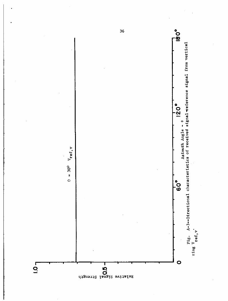
APPENDIX A
The following figures demonstrate the angular dependence of the
various received signals.
33

I I
0 -
. 34
0 0 l-l
II
a)
0
8
I
aJ l-l M 8 c U at E rl
4
rl (d V rl U k aJ ? E 0 k W rl 91 C M .I4 m aJ c) C aJ k aJ w aJ & I
l-l at C bo rl m CCI aJ ? .I4 aJ 0 9) &
w 0
c) d U m ?-I k aJ U V at k at
m
5 l-l at C 0 4 U 0 aJ & rl ca I I rl
2 s w
. a J M & 4 3 F
M C 4 &

I .
I
0 0 N
II
CD
3 w Q)
2
0 0 cv
I;
CD
35
1 I 1 ---
D
0 0
d a V rl U Fc Q) 3
E k lu
d a E: M .I4 I
Q) L) G PI Fc 01 w Q)
d al E: M rl 0
f.’
0 0 CD
0
0 0 Q) -
0 0 *a -
36
0 0 'a
0
rl & al U 0 a & nt
5 rl a C 0 rl U c) al & 4
? I
Fl
- . W M a l 4 M F . t 3
M C rl &

37
I I I I I I I I
In 0
. a J M F c
0

I .
I ' 38
? W aJ
P 0 0 In
II
a)
0
4 a 0 d U $4
$ E 0 I4 ru l-i a G M d m PI
0, $4 Q) W Q) $4 8 l-i a G M d m 73
d Q) 0 aJ $4
W 0 m c) d U m d $4 aJ U 0 a $4 a
2
$
5

39
I
3
0 0 W
II
a
rl ai u d u
3 5 Fc w rl ai c M d m
aJ 0 C aJ Fc aJ w aJ Fc I rl ai c M 1-I m 71 aJ
e ? 1-I
I a J 0 aJaJ
4 N M c u 4 0
s m u 0
1 - I m E
0 0 '(D
0

40 0
0 0 '(0
0
M G 4 Fc

41
rl a C M rl m
0

42
0 rc) n
0 0 00 -rl a
c) rl c, M
$ E 0 M W
rl a c 0 rl c, c) aJ M 4 n

43 0 0 I1
aJ 4 a U G 0 N 4 k 0 c E 0 k
rc(
m a G M 4 m aJ m al
r(
Ji a t rl a M 4 m -0
4 aJ c) al k
0
0 4 U m
9-4 k aJ U 0
$
m

44 0 0
0
a, - 4
ai U C 0 N d &I 0
D 0 cu -
0 0 m
0
z & w m rl ai C M 4 m
aJ m ([I s a I rl tu c bo 4 m m aJ > 4 aJ V aJ &
w 0 m 0 4 u m 4 & aJ u V
2 . i b c S - E v 3

0 0 CJ
II
CD
45 0 0
4 UJ U C 0 N d &I 0
JZ
E 0 &I w m rl (d C M d m
PI a UJ c a I rl UJ C bo d m
-0 : 4 aJ V aJ &I
w 0
m 0 d U m d Ll aJ U 0 UJ & I * cdc C - E u 3 a s r l r
2 5- d u c 0 0 a l d &Iu
d U J
I d l h
N U J rlrl I O
n~

46
0 0 m II
CD
rl a U c 0 N -4 Fc 0 c s Fc u-l
rn a C M 4 rn aJ rn at s a t rl at C M d rn
rl
‘cl
d Q) 0 a Fc
rer 0
rn 0 d U
-4 Fc aJ U 0 a . Fcc a - E c 3 u d a s E: --? 0 3 4 u c v o a J d M U . c ( ( o
1 4 I F c
m a drl I O
CD MFc 4 0 FrrW
M c d Fc
f
m
L
n~
v

47 0
0 0 4
I . " . I " " I " " s cu
0 Q) -
0 0 'N -
0 .o CD
0
4 (d u C 0 N d Fc 0 c
Fc W
m ri (d G M d m
aJ m (d s a I
l-4 (d C M
I O 4 ?
M E: d Fc

48
0 0 m s E
3
i \ 9 9 N
0 0 Q 0
0 0 6 J -
0 0
0
. 49
d 6 U C 0 N d k 0 c E 0 Ll
%I
m
a C M d m ai m a P a
I rl a C M d m
r(
'0
$ d ai V ai k
%I 0
m 0 d U m rl Ll ai u V a L l . cos s >E
L- r ( r a s
rl u c 0 0 a i d
4: n~ I d I &
\ D Q rld I O
aJ MLl 4 0 ku4
M C d h
v

50
- J= E
3
D 0 cu I)
0 0 'u)
0
d 4 U C 0 N d & 0 c E 0 & w m d B G M 4 m
aJ m 4 c ? I4 a! c M 4 m 'c)
d P) 0 P) &
w 0 m V d u m d & aJ u 0 4 L l .
?
k l c A - E v 3 d - 4 E c-4 0 3
drl I O
a v
M c d &

,
0 0
0 d
0 0 m
I1
0 f4 0 ic(
0
II
S E
3 'c1 G (d
.. 0 U 0 z
51
0 0 03
I1
a,

0 0
II
(D
k O
W
0
II
3 W al k
.. >
..
52
0 0
I I I I I I 1 I
u)
0 9 -
rc 0 U C O N .rl k 0 c F/ k W
rl a C M 4 m
aJ k I rl 41 C M 4 m 'cl
4 aJ 0 aJ k
IC1 O m
$
v 4 U 0
53 0
'ai
5 k
W
rl a c M 4 m aJ c) c aJ k PI q_c aJ k I 4 a c bo 4 m -0
$

54 1--( (d u c 0 N rl Fc 0 c
Fc w d (d C M .I4 rn
Fc I r( (d c M d m
Fc
W 0 rn u
M c d Fc

55 0 0 Q) - w
B 0 cu w
8
I
aJ l4 M C -4 c c, 7 E d
4
0 (0
#
0
rl a u C 0 N d &I 0 c 5 &I
u-4
4 a C M d rn aJ 0 C aJ &I aJ
u-4 aJ &I I
l-4 a C M d rn
'p aJ ? d aJ 0 aJ &I
w 0 0 0 .r( U m d &4 aJ c, c) a & I - a * E . . v w
aJ r c F c a 3 C 0 1 d U C 0 0 a J d & I - d a I d l & I
cva e l4 I O
n~
v 8
M U d o k l w
M C d Fc

56
I . I
9 U
I I I . I
0 ,a0
0 l-4 a U C 0 N d Fc 0 s E 0 Fc w r-i a C M d a aJ 0 C aJ Fc aJ w OI k I
r-i a fi M d m w
d aJ 0 aJ Fc
w 0
a 0 *-( u m d Fc aJ u 0 a F c * a s c - u w aJ
$
I4 a 2 C 0 1 4 u f i 0 0 a J d M U d a I d I F c
m a o l d I O
-3
M k d o k l w
M fi d k
n~
4 ?

57 0 0

58
c W 01
2 I 0 0 I-
ll
0
0
1 I I 1 I 1 1 I 1
0

8
59
d a U c 0 N 4
E 0 84 w
M G 4 Fc

60
1 I m J . n
I 1 I
0' 9 -

P 61
c Q?

0 0 rl
II
CD
62
2 d &
0

63 0 Q -
0 (u -
e I
9) d M
4 c
2 3 .O u)
0
rl a) U c 0 N .d &I 0 c E &I
W
m a) c bo 1.1 m 9) m a) c a I d a) c !!n 1.1 m -0
1.1 9) 0 9) &I
W 0
0 1.1
1.1 td 9) u 0 9 s c
c 0 -
l-l
d
a
t u
2 +-E
a) >- c
c 0 1 1.1 u c 0 0 411.1 & I & 1.1s Q N 1 1 . 1 I k o s
r n d 4; e
M U 1.10 k W
z r( &I

0 0 m II
0
64
Fl a u c 0 N d & 0 c E 0 & W
m I4 a C M d 0
al m 0 c a I rl a c M d a 5
d al 0 PI &
W 0 m c)
5
ri - a rl & al

0 0 .e It
(D
65
4 0 U C 0 N rl r 0 .c
r VI
m rl 6 C M rl m aJ m 6 s ? rl 6 C bG 4 m w a8 3 rl QI 0 01 r W 0

66
0 0 m 1-I
Lc 0 .c
m d
d M

67
0 0 \o

68 c
0 0 b
ll
(D
rl 6 U I= 0 N d &A 0 c
i? & w W d 91 C bo d W
01 a 6 A a
I rl 6 E M d a ‘0
d al 0 01 Lc
w 0
s

69
0 0 .a0
II
(D
L p sua Z'

0 0 *
It
(D
70
E 0 & u.r P rl 6 c bo d a al
c a I d a G bo 4 rn Q
d 9) 0 a8 &
vc 0
0 d u P d & 9)
:
$
a

APPENDIX B
The following is the computer program used to compute the nor-
malized directional characteristics of the received signal. The quan-
t i t i e s l i s t e d below are referred to by the equation number in the
body of the report.
PROGRAM SYMBOL
V1
v2
v3
v4
v5
v7
'6
71

i -
t
72