Ekinops Data Center Application Brief any mix of GbE, 1/2/4GFC, OC-12/STM-4, OC-48/STM-16 EKINOPS PM...
4
■ MARKET REQUIREMENT ■ CHALLENGES In recent years, a growing number of enterprise companies and network operators have put more emphasis on disaster recovery and business continuance. These plans call for replication and centralization of critical information within multiple data centers. This is achieved through the interconnecting of two or more on-net or off-net (Colo). In addition to being used for disaster recovery, these networks are also used to replicate localized data to improve user experience (ex: peering, content delivery). The transmission of business critical information among data centers has unique requirements and challenges which can not always be solved with transport equipment that was designed for telecommunications service providers. For example, data centers must make efficient use of floor space and power. Adding and upgrading facilities is extremely costly. Therefore, data center solutions must require minimum space, require minimum power, but provide the scalability, flexibility and simplicity to support the growth and applications of the future. ≥ Ability to leverage existing infrastructure and avoid costly facility upgrades (power, space / real-estate) ≥ Ability to easily and cost-effectively add capacity to accommodate traffic growth (10Gbps, 100Gbps, n x 100Gbps) ≥ Ability to transport and offer a variety of enterprise protocols (SAN, Gigabit Ethernet, SONET, etc.) without the introduction of multiple platforms ≥ Ability to quickly and economically adapt the network in support of future technologies and services ≥ Ability to minimize the cost of real-estate and power for co-location applications ≥ Ability to keep things simple and efficient in an attempt to control on-going operational expenses ■ EKINOPS’ SOLUTION Ekinops’ Data Center Solutions offer a number of advantages over other common data center solutions. In addition to supporting a wide variety of applications and service rates, we leverage the unique capabilities of the Ekinops 360 Multi-Protocol, Multi-Reach, Next Generation Transport System to provide many other differentiating advantages that are important to data center operators. ■ EKINOPS360 ® is a compact and operationally efficient platform that helps data center operators make the most of their existing space and power — no costly upgrades. ■ T CHIP ® technology offers all optical transport features and capabilities on a single, next-generation programmable chip — providing improved performance and flexibility. ■ DYNAFEC ® is one of Ekinops’ T CHIP ® programmable features that provides an enhanced forward error correction (FEC) — maintaining industry-leading optical performance regardless of distance. ■ Even though Ethernet and SAN protocols are the dominant data center protocols, the EKINOPS360 ® solution supports other legacy and next-generation services as well. ■ The Ekinops solution can be an economical and effective means to add capacity to any legacy transport network — proven interoperability means it can be deployed in an alien (foreign) wavelength application over your existing transport network. ■ The Ekinops’ DYNAMUX ® capability (Dynamic Multiplexing) allows for efficient multiplexing of any protocol mix over a wavelength or any service type. ■ Single fiber transport capability for fiber constrained environments or environments where fiber is expensive or being leased. ■ Fiber Channel Encryption adhering to Encryption Standards required by most Governments. > ▼ ▼ E K I N O P S P R O P R I E T A R Y I N F O R M A T I O N : : A L L R I G H T S R E S E R V E D EKINOPS DATA CENTER SOLUTIONS APPLICATION BRIEF 06 | 2014
Transcript of Ekinops Data Center Application Brief any mix of GbE, 1/2/4GFC, OC-12/STM-4, OC-48/STM-16 EKINOPS PM...

■ MARKET REQUIREMENT
■ CHALLENGES
In recent years, a growing number of enterprisecompanies and network operators have put more emphasis ondisaster recovery and business continuance.
These plans call for replication and centralization of criticalinformation within multiple data centers. This is achievedthrough the interconnecting of two or more on-net or off-net(Colo). In addition to being used for disaster recovery, thesenetworks are also used to replicate localized data to improveuser experience (ex: peering, content delivery).
The transmission of business critical information among datacenters has unique requirements and challenges which can notalways be solved with transport equipment that was designedfor telecommunications service providers. For example, datacenters must make efficient use of floor space and power.
Adding and upgrading facilities is extremely costly. Therefore,data center solutions must require minimum space, requireminimum power, but provide the scalability, flexibility andsimplicity to support the growth and applications of the future.
≥ Ability to leverage existing infrastructure and avoid costlyfacility upgrades (power, space / real-estate)
≥ Ability to easily and cost-effectively add capacityto accommodate traffic growth (10Gbps, 100Gbps, n x 100Gbps)
≥ Ability to transport and offer a variety of enterpriseprotocols (SAN, Gigabit Ethernet, SONET, etc.)
without the introduction of multiple platforms
≥ Ability to quickly and economically adapt the network in support of future technologies and services
≥ Ability to minimize the cost of real-estateand power for co-location applications
≥ Ability to keep things simple and efficientin an attempt to control on-going operational expenses
■ EKINOPS’ SOLUTIONEkinops’ Data Center Solutions offer a number of advantagesover other common data center solutions. In addition tosupporting a wide variety of applications and service rates,we leverage the unique capabilities of the Ekinops 360 Multi-Protocol, Multi-Reach, Next Generation Transport Systemto provide many other differentiating advantages that areimportant to data center operators.
■ EKINOPS360® is a compact and operationally efficient platformthat helps data center operators make the most of their existingspace and power — no costly upgrades.
■ T CHIP ® technology offers all optical transport features andcapabilities on a single, next-generation programmable chip —providing improved performance and flexibility.
■ DYNAFEC® is one of Ekinops’ T CHIP®programmable features thatprovides an enhanced forward error correction (FEC) — maintainingindustry-leading optical performance regardless of distance.
■ Even though Ethernet and SAN protocols are the dominant datacenter protocols, the EKINOPS360®solution supports other legacyand next-generation services as well.
■ The Ekinops solution can be an economical and effectivemeans to add capacity to any legacy transport network — proveninteroperability means it can be deployed in an alien (foreign)wavelength application over your existing transport network.
■ The Ekinops’ DYNAMUX® capability (Dynamic Multiplexing) allowsfor efficient multiplexing of any protocol mix over a wavelength orany service type.
■ Single fiber transport capability for fiber constrained environmentsor environments where fiber is expensive or being leased.
■ Fiber Channel Encryption adhering to Encryption Standardsrequired by most Governments.
>
▼
▼
E K I N O P S P R O P R I E T A R Y I N F O R M A T I O N : : A L L R I G H T S R E S E R V E D
EKINOPSDATA CENTER SOLUTIONS
APPLICATION BRIEF 06 |2014
REV 08 2015 Ekinops Data Center Application Brief_Mise en page 1 31/08/15 11:21 Page1

E K I N O P S P R O P R I E T A R Y I N F O R M A T I O N : : A L L R I G H T S R E S E R V E D
The following is a summary of Ekinops 360 data center platforms and service and transportmodules offered by Ekinops to support a variety of data center applications.
>
FEATURES
Height 7RU (12.25“) 2RU (3.50“) 1RU (1.75“)
Width 19.00” 19.00” 19.00”
# Slots 20 Slots 6 Slots Fixed Configuration
Power Consumption 720 W 110 W 200 W
DC Power Standard Standard Standard
AC Power Optional Optional Optional
HC
600HC 200 RRM
RMCHASSISOPTIONS
AGGREGATIONMODULES
TRANSPONDERMODULES
SERIES
EKINOPS PM 253Aggregates
2xGbE/1GFC to 2.5G
EKINOPS PM 404GbE, Fast Ethernet,
1/2/4 GFC
EKINOPS PM 801RR8GFC Transponder
EKINOPS PM 1001RR10GbE, 10GFC, OTU2,
OC192/STM64
EKINOPS PM 10001100GbE
EKINOPS PM C1008MPAggregates any mix of GbE, 1/2/4GFC,
OC-12/STM-4, OC-48/STM-16
EKINOPS PM 10010MPAggregates 10GbE, 40GbE, OTU1e, OTU2,
OTU2e, 8/10/16GFC*, OC192/STM64
* Note: Please contact your Ekinops sales representative regarding availability date for 16GFC on PM 10010MP.
■ HIGH-CAPACITY DATA CENTER INTERCONNECTThe Ekinops 360 Data Center Solution offers all features and functionality required to support a multi-data center network.
Depending on the data center environment and requirements,Ekinops provides multiple chassis systems (all of which leverage thesame hardware and software) that can be designed and configuredto meet your specific needs. So whether you facilities supportEthernet, SAN, or any other service type (video, OTN, SONET), theEkinops 360 solution has a service module that simply plugs into theselected chassis. The scalability of the systems also allows you toincrease capacity as business needs dictate — a true ‘Pay As YouGrow’ model; whether that is 10G, 40G or 100G today.
For example, the RM10010/10001 is a software programmablemuxponder and transponder in a 1RU (1.75”) footprint. So you canstart by muxing multiple 8GFC, 10GFC, or 10GbE over a 100GbEline, and then migrate the platform to a 100GE transponder in thefuture. And through the introduction of DYNAFEC®, Ekinops canmaintain best-in-class optical performance and efficiency even ifthe data centers are separated by great distance.
10G / 40G / 100G
Data Center Data Center
Ethernet
SAN
Video
OTN
SONET
| 2
REV 08 2015 Ekinops Data Center Application Brief_Mise en page 1 31/08/15 11:21 Page2
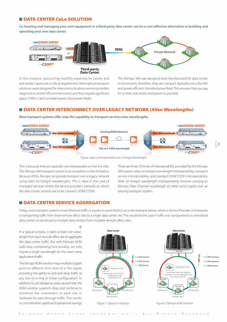
Figure 1: Typical in Industry
3 Wavelengths Point-To-Point3 Aggregation Cards
at Aggregation Site
Remote Site 1 Remote Site 3
Remote Site 2
= Aggregation Card
= 3 SAN Services
= 2 SAN Services
= 1 SAN Service
Data Center
■ DATA CENTER CoLo SOLUTIONCo-locating and managing your own equipment in a third-party data center can be a cost-effective alternative to building andoperating your own data center.
In this instance, reoccurring monthly expenses for power andreal-estate / space are a critical requirement. Most optical transportsolutions were designed for telecommunications service providers(large hub or central office environments) and thus require significantspace (14RU+) and consider power (dual power feeds).
The Ekinops 360 was designed and manufactured for data centerenvironments; therefore, they are compact (typically only a few RU)and power efficient (standard power feed). This ensures that you payfor as little real-estate and power as possible.
100G
Third-partyData Center
or
RRM
200
1RU
2RU
Private Network
Existing WDM Network
10G or a 100G wavelengthNew 10G wavelength New 10G wavelength
New 100G wavelength New 100G wavelength
200 200
RRMRM
■ DATA CENTER INTERCONNECT OVER LEGACY NETWORK (Alien Wavelengths)Most transport systems offer only the capability to transport services over wavelengths.
This is because they are typically not interoperable on the line side.The Ekinops 360 transport system is an exception to this limitation.Because of this, Ekinops can provide transport over a legacy networkusing alien (or foreign) wavelengths. This is ideal in the case ofmanaged services where the service provider’s network on whichthe data center services are to be carried is SONET/SDH.
There are three (3) levels of interoperability provided by the Ekinops360 system, alien (or foreign) wavelength interoperability, transportservice interoperability, and standard SONET/SDH interoperability.Alien (or foreign) wavelength interoperability involves carrying anEkinops Fiber Channel wavelength (or other service types) over anexisting transport system.
■ DATA CENTER SERVICE AGGREGATION
Today, most transport systems move Ethernet traffic in a point to point fashion as in the example below, where a Service Provider or Enterpriseis transporting traffic from three remote office sites to a single data center site. This would be the case if traffic was transported to a centralizeddata center (or distributed to multiple data centers) from multiple remote office sites.
>
In a typical scenario, it takes at least one wave-length from each remote office site to aggregatethe data center traffic. But with Ekinops ADM(add-drop multiplexing) functionality, we onlyrequire a single wavelength for the exact sameapplication/traffic.
The Ekinops’ ADM solution maps multiple Gigabitports to different time slots of a 10G signal;providing the ability to add and drop traffic atany site on a ring or linear configuration. Inaddition to just dropping waves at each site, theADM solution supports drop and continue tominimize the investment at each site inhardware for pass through traffic. This resultsin considerable capital and operational savings.
E K I N O P S P R O P R I E T A R Y I N F O R M A T I O N : : A L L R I G H T S R E S E R V E D
Figure: Legacy Interoperability via a Foreign Wavelength
Figure 2: Ekinops ADM Solution
= 3 SAN Services
= 2 SAN Services
= 1 SAN Service= Aggregation Card
1 Wavelength Add Drop Capability
1 Aggregation Card at Aggregation Site
50ms Ring Protected
Remote Site 1 Remote Site 3
Remote Site 2
PM C1008
Data Center
PM C1008
PM C1008
PM C1008
| 3
REV 08 2015 Ekinops Data Center Application Brief_Mise en page 1 31/08/15 11:21 Page3
© E
KIN
OPS
S.A
.- 0
8 20
15 -
V.0
02 -
All
rig
hts
rese
rved
Ekinops is a leading supplier of next generation optical transport equipmentfor telecommunications service providers. The EKINOPS360® addresses Metro,Regional, and Long-Haul applications with a single, highly-integrated platform.
Ekinops is a market-leading innovator in 100G transport with a coherent lineof products that truly optimizes optical networks and comes in 1RU, 2RU or7RU chassis. The EKINOPS360® relies on the highly-programmable Ekinops
T CHIP® (Transport-on-a-Chip) architecture that enables fast, flexible andcost-effective delivery of new services for high-speed, high-capacity transport.Using the EKINOPS360® carrier-grade system, operators can simply increasecapacity of their networks — CWDM, DWDM, Ethernet, ESCON, Fiber Channel,SONET/SDH, and uncompressed video (HD-SDI, SD-SDI, ASI).
▼
ABOUT EKINOPS
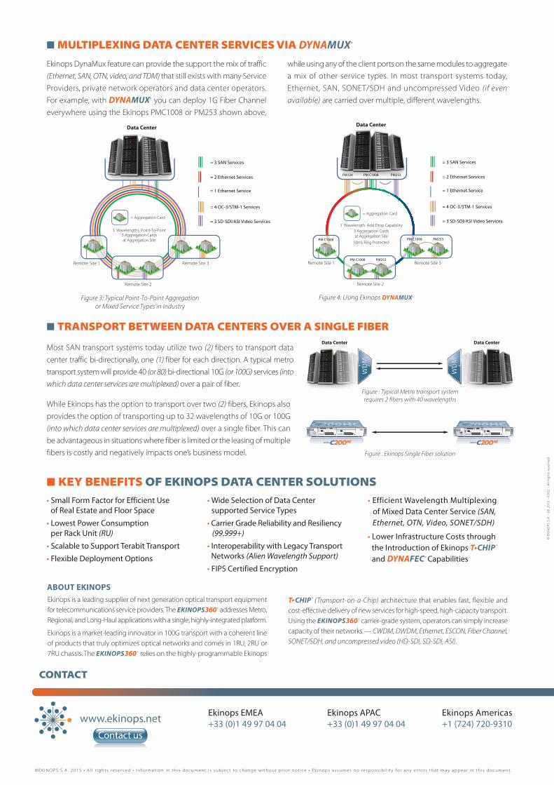
■ MULTIPLEXING DATA CENTER SERVICES VIA DYNAMUX®
Figure 3: Typical Point-To-Point Aggregationor Mixed Service Types in Industry
Figure 4: Using Ekinops DYNAMUX®
= 3 SAN Services
= 2 Ethernet Services
= 1 Ethernet Service
= 4 OC-3/STM-1 Services
= 3 SD-SDI/ASI Video Services
3 Wavelengths Point-To-Point3 Aggregation Cards
at Aggregation Site
Remote Site 1 Remote Site 3
Remote Site 2
= Aggregation Card
Data Center
Data CenterData Center
200 200
Data Center
PM124 PM C1008 PM253
= 3 SAN Services
= 2 Ethernet Services
= 1 Ethernet Service
= 4 OC-3/STM-1 Services
= 3 SD-SDI/ASI Video Services1 Wavelength Add Drop Capability
3 Aggregation Cards
at Aggregation Site
50ms Ring Protected
Remote Site 1 Remote Site 3
Remote Site 2
= Aggregation Card
PM C1008 PM C1008 PM253
PM C1008 PM253
Ekinops DynaMux feature can provide the support the mix of traffic(Ethernet, SAN, OTN, video, and TDM) that still exists with many ServiceProviders, private network operators and data center operators.For example, with DYNAMUX® you can deploy 1G Fiber Channeleverywhere using the Ekinops PMC1008 or PM253 shown above,
while using any of the client ports on the same modules to aggregatea mix of other service types. In most transport systems today,Ethernet, SAN, SONET/SDH and uncompressed Video (if evenavailable) are carried over multiple, different wavelengths.
■ TRANSPORT BETWEEN DATA CENTERS OVER A SINGLE FIBER
Most SAN transport systems today utilize two (2) fibers to transport datacenter traffic bi-directionally, one (1) fiber for each direction. A typical metrotransport system will provide 40 (or 80) bi-directional 10G (or 100G) services (intowhich data center services are multiplexed) over a pair of fiber.
■ KEY BENEFITS OF EKINOPS DATA CENTER SOLUTIONS• Small Form Factor for Efficient Use
of Real Estate and Floor Space
• Lowest Power Consumptionper Rack Unit (RU)
• Scalable to Support Terabit Transport
• Flexible Deployment Options
• Wide Selection of Data Centersupported Service Types
• Carrier Grade Reliability and Resiliency(99.999+)
• Interoperability with Legacy TransportNetworks (Alien Wavelength Support)
• FIPS Certified Encryption
• Efficient Wavelength Multiplexingof Mixed Data Center Service (SAN,Ethernet, OTN, Video, SONET/SDH)
• Lower Infrastructure Costs throughthe Introduction of Ekinops T CHIP®
and DYNAFEC® Capabilities
▼
While Ekinops has the option to transport over two (2) fibers, Ekinops alsoprovides the option of transporting up to 32 wavelengths of 10G or 100G(into which data center services are multiplexed) over a single fiber. This canbe advantageous in situations where fiber is limited or the leasing of multiplefibers is costly and negatively impacts one’s business model.
Figure : Typical Metro transport systemrequires 2 fibers with 40 wavelengths
Figure : Ekinops Single Fiber solution
www.ekinops.net Ekinops EMEA Ekinops APAC Ekinops Americas+33 (0)1 49 97 04 04 +33 (0)1 49 97 04 04 +1 (724) 720-9310
CONTACT
© E K I N O P S S . A . 2 0 1 5 • A l l r i g h t s r e s e r v e d • I n fo r m a t i o n i n t h i s d o c u m e n t i s s u b j e c t t o c h a n g e w i t h o u t p r i o r n o t i c e • E k i n o p s a s s u m e s n o r e s p o n s i b i l i t y fo r a n y e r r o r s t h a t m a y a p p e a r i n t h i s d o c u m e n t .
REV 08 2015 Ekinops Data Center Application Brief_Mise en page 1 31/08/15 11:21 Page4