Ekinops Application Note - Cost Effective ROADM Solution
7
Figure 1. Examples of 2 and 4 Degree ROADM Network Elements with local add-drop traffic Degree 1 Degree 2 Local Add/Drop Degree 2 ROADM E K I N O P S P R O P R I E T A R Y I N F O R M A T I O N : : A L L R I G H T S R E S E R V E D ••• BUILDING A COST EFFECTIVE, AFFORDABLE, AND SCALABLE ROADM BASED OPTICAL NETWORK ROADMs are a disruptive technology that have and will continue to benefit the industry in many ways. ROADM technology allows Service Providers network flexibility without major up front planning or future reconstruction of the network to accommodate unforeseen service demand. In addition, ROADM technology holds a very promising future in the realization of all optical switching and protection. ROADMs do still have one inhibitor to ubiquitous deployment in all networks however. This inhibitor is up front cost. Most ROADM solutions available in the industry today are many times more expensive than fixed filter solutions and whether or not this extra cost is worth the investment is still in debate. There are some lower cost older generation ROADM solutions available (like Planar Lightwave Circuit, PLC ROADMs for instance) but these solutions have often fallen short in scalability or functionality to the extent that newer WSS (Wave Selective Switch) based ROADMs are preferred. For instance, many of the PLC based ROADMs had limitations in the number of degrees supported or in their ability to transport and switch 40Gig wavelengths. :: So, is there a compromise between cost and flexibility that can be achieved? The answer is yes. Although, ROADMs will likely be more expensive than fixed filters for a very long time, the answer to allowing a ROADM solution to scale in cost with the service provider’s needs lies in the implementation of ROADM network elements using available off-the-shelf WSS ROADM technologies. To understand this better, let’s talk a little about WSS ROADM technology choices that ROADM solution providers offer. First to level set, let’s be clear on what we mean by a 2 degree or 3 degree ROADM network elements. The diagram below shows an example of 2 and 4 degree ROADM network elements with local add drop traffic. In the figure 1 above, a 2 degree ROADM network element is a network node that can add and drop traffic locally to or from 2 directions in the network (right and left in the diagram above). A four degree ROADM network element is a network node that can add and drop traffic locally to or from 4 directions in the network (right, left, up, and down in the diagram above). In the industry, it is now generally accepted that any ROADM network element should be able to scale to 8 degrees and drop any channel from any degree locally with no limitation. APPLICATION NOTE Degree 1 Degree 2 Degree Degree 4 Local Add/Drop gre e 1 Degre e 3 Degre e 4 Degree 4 ROADM
-
Upload
srotenstein3114 -
Category
Documents
-
view
243 -
download
3
description
App note
Transcript of Ekinops Application Note - Cost Effective ROADM Solution
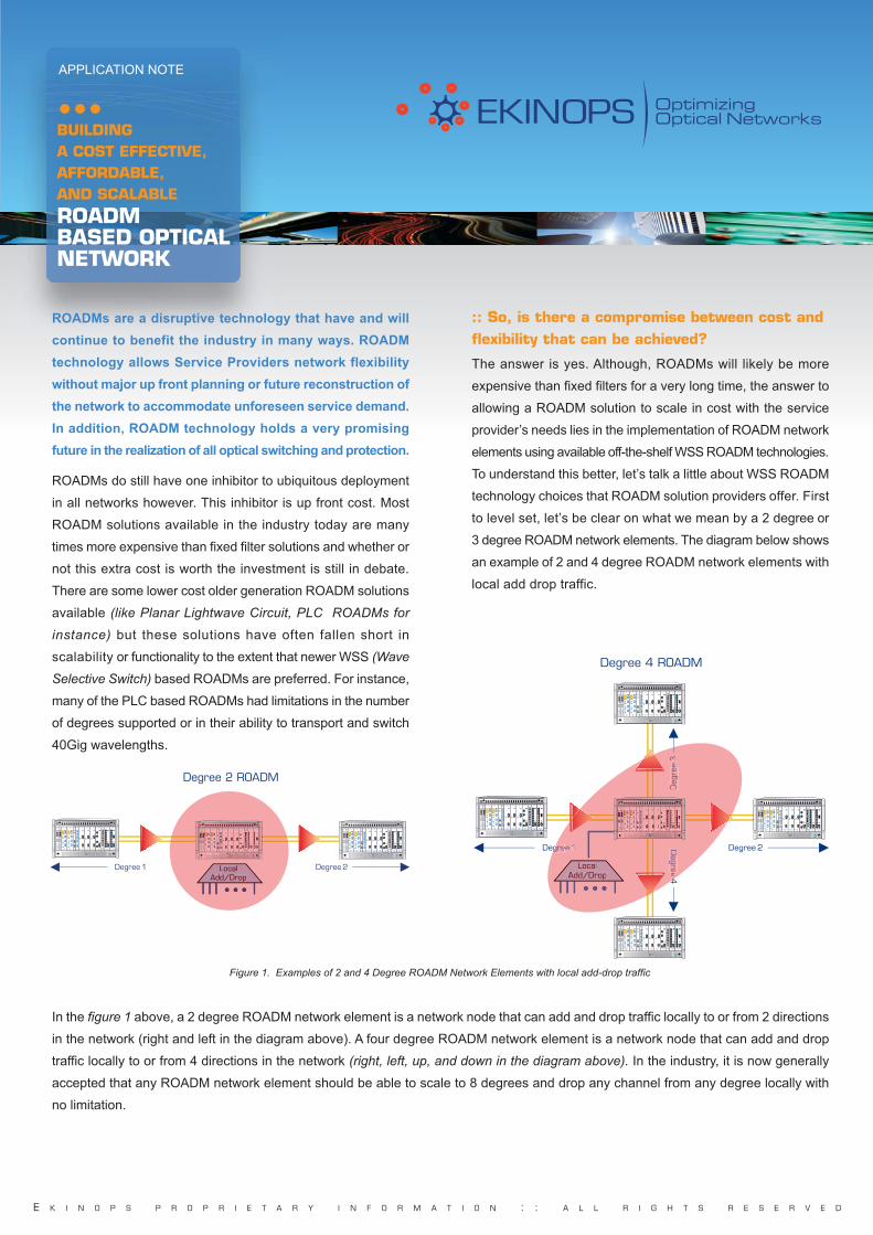
Figure 1. Examples of 2 and 4 Degree ROADM Network Elements with local add-drop traffic
LocalAdd/Drop
Degree 1 Degree 2
PM
Serie
sEK
INO
PS
PM
Serie
sEK
INO
PS
PMOA PM1001 PM1001 PM1001 PM1004 PM1008 PM1005PMOA PMOSC PMOM4 PM253
PM
Serie
sEK
INO
PS
PM
Serie
s
PM
Serie
sEK
INO
PS
PM
Serie
sEK
INO
PS
PMOA PM1001 PM1001 PM1001 PM1004 PM1008 PM1005PMOA PMOSC PMOM4 PM253
LocalAdd/Drop
PM
Serie
sEK
INO
PS
PM
Serie
s
Degree 2 ROADM
E K I N O P S P R O P R I E T A R Y I N F O R M A T I O N : : A L L R I G H T S R E S E R V E D
•••BUILDING A COST EFFECTIVE,AFFORDABLE, AND SCALABLE
ROADM BASED OPTICALNETWORK
ROADMs are a disruptive technology that have and will
continue to benefit the industry in many ways. ROADM
technology allows Service Providers network flexibility
without major up front planning or future reconstruction of
the network to accommodate unforeseen service demand.
In addition, ROADM technology holds a very promising
future in the realization of all optical switching and protection.
ROADMs do still have one inhibitor to ubiquitous deployment
in all networks however. This inhibitor is up front cost. Most
ROADM solutions available in the industry today are many
times more expensive than fixed filter solutions and whether or
not this extra cost is worth the investment is still in debate.
There are some lower cost older generation ROADM solutions
available (like Planar Lightwave Circuit, PLC ROADMs for
instance) but these solutions have often fallen short in
scalability or functionality to the extent that newer WSS (Wave
Selective Switch) based ROADMs are preferred. For instance,
many of the PLC based ROADMs had limitations in the number
of degrees supported or in their ability to transport and switch
40Gig wavelengths.
:: So, is there a compromise between cost andflexibility that can be achieved?
The answer is yes. Although, ROADMs will likely be more
expensive than fixed filters for a very long time, the answer to
allowing a ROADM solution to scale in cost with the service
provider’s needs lies in the implementation of ROADM network
elements using available off-the-shelf WSS ROADM technologies.
To understand this better, let’s talk a little about WSS ROADM
technology choices that ROADM solution providers offer. First
to level set, let’s be clear on what we mean by a 2 degree or
3 degree ROADM network elements. The diagram below shows
an example of 2 and 4 degree ROADM network elements with
local add drop traffic.
In the figure 1 above, a 2 degree ROADM network element is a network node that can add and drop traffic locally to or from 2 directions
in the network (right and left in the diagram above). A four degree ROADM network element is a network node that can add and drop
traffic locally to or from 4 directions in the network (right, left, up, and down in the diagram above). In the industry, it is now generally
accepted that any ROADM network element should be able to scale to 8 degrees and drop any channel from any degree locally with
no limitation.
APPLICATION NOTE
LocalAdd/Drop
Degree 1 Degree 2
PM
Serie
sEK
INO
PS
PM
Serie
sEK
INO
PS
PMOA PM1001 PM1001 PM1001 PM1004 PM1008 PM1005PMOA PMOSC PMOM4 PM253
PM
Serie
sEK
INO
PS
PM
Serie
sEK
INO
PS
PMOA PM1001 PM1001 PM1001 PM1004 PM1008 PM1005PMOA PMOSC PMOM4 PM253
PM
Serie
sEK
INO
PS
PM
Serie
sEK
INO
PS
PMOA PM1001 PM1001 PM1001 PM1004 PM1008 PM1005PMOA PMOSC PMOM4 PM253
PM
Serie
sEK
INO
PS
PM
Serie
sEK
INO
PS
PMOA PM1001 PM1001 PM1001 PM1004 PM1008 PM1005PMOA PMOSC PMOM4 PM253
Deg
ree
3
Degree
4
LocalAdd/Drop
gree 1
Deg
ree
3
Degree
4
Degree 4 ROADM
EKINOPS_WP_ROADM:Mise en page 1 19/01/09 12:21 Page 1

•••BUILDING A COST EFFECTIVE,AFFORDABLE, AND SCALABLE
ROADM BASED OPTICALNETWORK
APPLICATION NOTE
E K I N O P S P R O P R I E T A R Y I N F O R M A T I O N : : A L L R I G H T S R E S E R V E D
The key in scaling cost lies in the ROADM components used
by the ROADM network element manufacturer given that the
ROADM components used make up the majority of the cost of
the ROADM network element. There are a number of ROADM
optical components that could be used by transport vendors to
produce the 2 ROADM examples above. ROADM components
are classified by the number of degrees that they support.
For instance, a ROADM component that can support up to
2 degrees with local add drop of any channel coming from or
going to any of those degrees would be called a 1x2 ROADM.
Typically, one ROADM component is necessary for each
degree in a ROADM network element so, a 2 degree ROADM
network element would require 2 1x2 ROADM components.
A ROADM component that can support up to 4 degrees with
local add drop of any channels coming from or going to any of
those 4 degrees would be called a 1x4. A four degree
ROADM network element built with this component would
require 4 ROADM components, one for each degree.
As an example, the figure below shows how a 2 degree ROADM
network element is built from 1x2 ROADM components.
LocalAdd/Drop
Degree 1 Degree 2
PM
Serie
sEK
INO
PS
PM
Serie
sEK
INO
PS
PMOA PM1001 PM1001 PM1001 PM1004 PM1008 PM1005PMOA PMOSC PMOM4 PM253
PM
Serie
sEK
INO
PS
PM
Serie
s
PM
Serie
sEK
INO
PS
PM
Serie
sEK
INO
PS
PMOA PM1001 PM1001 PM1001 PM1004 PM1008 PM1005PMOA PMOSC PMOM4 PM253
LocalAdd/Drop
PM
Serie
sEK
INO
PS
PM
Serie
s
Degree 2 ROADM
LocalAdd/Drop
West Channels East Channels
LocalAdd/Drop
PM
Serie
sEK
INO
PS
PM
Serie
sEK
INO
PS
PMOA PM1001 PM1001 PM1001 PM1004 PM1008 PM1005PMOA PMOSC PMOM4 PM253
PM
Serie
sEK
INO
PS
PM
Serie
sEK
INO
PS
PMOA PM1001 PM1001 PM1001 PM1004 PM1008 PM1005PMOA PMOSC PMOM4 PM253
1 x 2 WSS1 x 2 WSS
In a ROADM network element, each ROADM component is
used to add and drop channels from a single degree. The
ROADM components are then interconnected to allow
channels to be connected from one degree to the other.
ROADM components have ports that allow for this optical inter-
connection as well as for the dropping of local channels. The
number of ports that a ROADM component has determines
how many degrees it can be interconnected with. In the example
above, the 1x2 ROADM component has 2 ports, one for local
add drop and one for interconnection to the 2nd ROADM
component necessary to support 2 degrees. So, the ROADM
network element in the example above has no more ports for
expansion and will forever be limited to 2 degrees unless traffic
is taken down and the ROADM components are replaced with
higher degree ROADM components. In order to allow for future
expansion, the above ROADM network element can be built
with 2 1x4 ROADM components that have 2 additional ports
each . This would allow for the addition of 2 more ROADM
components in the ROADM network element and upgrade the
ROADM network element from 2 degrees to 4 degrees. The
figures below show a 2 degree ROADM network element built
with 1x4 ROADM components and that same ROADM network
element upgraded to 4 degrees with the addition of two more
1x4 ROADM components.
LocalAdd/Drop
West Channels East Channels
LocalAdd/Drop
PM
Serie
sEK
INO
PS
PM
Serie
sEK
INO
PS
PMOA PM1001 PM1001 PM1001 PM1004 PM1008 PM1005PMOA PMOSC PMOM4 PM253
PM
Serie
sEK
INO
PS
PM
Serie
sEK
INO
PS
PMOA PM1001 PM1001 PM1001 PM1004 PM1008 PM1005PMOA PMOSC PMOM4 PM253
1 x 4 WSS1 x 4 WSS
Figure 2, A 2 Degree ROADM Network Element Built Using 1x2 WSS ROADM Components
Figure 3, A 2 Degree ROADM Network Element Built Using 1x4 WSS ROADM Components
LocalAdd/Drop
Degree 1 Degree 2
PM
Serie
sEK
INO
PS
PM
Serie
sEK
INO
PS
PMOA PM1001 PM1001 PM1001 PM1004 PM1008 PM1005PMOA PMOSC PMOM4 PM253
PM
Serie
sEK
INO
PS
PM
Serie
s
PM
Serie
sEK
INO
PS
PM
Serie
sEK
INO
PS
PMOA PM1001 PM1001 PM1001 PM1004 PM1008 PM1005PMOA PMOSC PMOM4 PM253
LocalAdd/Drop
PM
Serie
sEK
INO
PS
PM
Serie
s
Degree 2 ROADM
EKINOPS_WP_ROADM:Mise en page 1 19/01/09 12:23 Page 2

•••BUILDING A COST EFFECTIVE,AFFORDABLE, AND SCALABLE
ROADM BASED OPTICALNETWORK
APPLICATION NOTE
E K I N O P S P R O P R I E T A R Y I N F O R M A T I O N : : A L L R I G H T S R E S E R V E D
Notice that in the 4 Degree ROADM network element, each
ROADM component uses all 4 of its ports. One port for local
add drop and the other 3 ports to interconnect with the other
ROADM components representing the other degrees of the
ROADM network element. So, why would one ever build a
2 degree ROADM network element with 1x2 ROADMs as
shown in figure 2 when the ROADM network element could
be built to be scalable as shown in figure 3 by using 1x4
ROADM components? This is where the dilemma arises when
designing ROADM network elements. The tradeoff is cost vs.
scalability. Of course, a 1x2 ROADM component is cheaper
than a 1x4 ROADM component so, scalability comes with a
price. The 2 degree ROADM network element is cheaper when
built with 1x2 ROADM components than it is when built with
1x4 ROADM components but, the 2 Degree ROADM network
element is scalable to 4 degrees when built with 1x4 ROADM
components whereas the 2 degree ROADM network element
built with 1x2 ROADM components is not.
Because the primary benefit of a ROADM network element is
to allow flexibility and scalability without planning, most transport
system vendors default to utilizing larger ROADM components
to build even lower degree ROADMs. The generally accepted
requirement for a ROADM network element is to allow for
8 degrees or more of expansion without traffic interruption.
Because of this, many system suppliers opt for utilizing 1x8
or larger ROADM components for all of their ROADM network
elements. This means that lower degree ROADM network
elements are more expensive than they need to be as most
ROADM network elements will always remain 4 degrees or
fewer and in fact many will always remain 2 degrees.
Another alternative would be to allow the service provider to
pick from a number of different ROADM network element
choices that are built from various degree ROADM components
allowing the customer to choose his own price vs. scalability
tradeoff. There is, however, a better solution. A solution that
allows for an optimal tradeoff of flexibility and price, regardless
of the size of the ROADM network element. What one can do
is utilize optical splitters/couplers to allow for the addition of
new ROADM components even if the ROADM component
initially used does not have any remaining ports. What an optical
splitter/coupler does is replicate all of the channels on a fiber
onto another fiber that can then be used to transfer all channels
to another ROADM component. The optical splitter is placed
in front of the existing ROADM component allowing for all
channels being received by that ROADM component to be
replicated and fed to a future ROADM component that will be
used to accommodate future degrees in the ROADM network
element. The figure below shows an example of a 1x2 network
element with optical Couplers/Splitters.
PM
Serie
sEK
INO
PS
PM
Serie
sEK
INO
PS
PMOA PM1001 PM1001 PM1001 PM1004 PM1008 PM1005PMOA PMOSC PMOM4 PM253
PM
Serie
sEK
INO
PS
PM
Serie
sEK
INO
PS
PMOA PM1001 PM1001 PM1001 PM1004 PM1008 PM1005PMOA PMOSC PMOM4 PM253
PM
Serie
sEK
INO
PS
PM
Serie
sEK
INO
PS
PMOA PM1001 PM1001 PM1001 PM1004 PM1008 PM1005PMOA PMOSC PMOM4 PM253
PM
Serie
sEK
INO
PS
PM
Serie
sEK
INO
PS
PMOA PM1001 PM1001 PM1001 PM1004 PM1008 PM1005PMOA PMOSC PMOM4 PM253
LocalAdd/
Drop
North C
hannels
1 x 4
WSS
LocalAdd/Drop
East Channels
1 x 4 WSS
LocalAdd/Drop
West Channels
1 x 4 WSS
1 x
4 W
SS
Loca
lAdd
/D
rop
Sou
th C
hann
els
Figure 4, A 4 Degree ROADM Network Element Built Using 1x4 WSS ROADM Components
Figure 5, A 2 Degree ROADM Network Element BuiltUsing 1x2 WSS ROADM Components with a Splitter/Coupler
for future expansion
LocalAdd/Drop
Degree 1 Degree 2
PM
Series
EK
INO
PS
PM
Series
EK
INO
PS
PMOA PM1001 PM1001 PM1001 PM1004 PM1008 PM1005PMOA PMOSC PMOM4 PM253
PM
Series
EK
INO
PS
PM
Series
EK
INO
PS
PMOA PM1001 PM1001 PM1001 PM1004 PM1008 PM1005PMOA PMOSC PMOM4 PM253
PM
Series
EK
INO
PS
PM
Series
EK
INO
PS
PMOA PM1001 PM1001 PM1001 PM1004 PM1008 PM1005PMOA PMOSC PMOM4 PM253
PM
Series
EK
INO
PS
PM
Series
EK
INO
PS
PMOA PM1001 PM1001 PM1001 PM1004 PM1008 PM1005PMOA PMOSC PMOM4 PM253
Deg
ree
3
Degree
4
LocalAdd/Drop
gree 1
Deg
ree
3
Degree
4
Degree 4 ROADM
LocalAdd/Drop
West Channels East Channels
LocalAdd/Drop
PM
Serie
sEK
INO
PS
PM
Serie
sEK
INO
PS
PMOA PM1001 PM1001 PM1001 PM1004 PM1008 PM1005PMOA PMOSC PMOM4 PM253
PM
Serie
sEK
INO
PS
PM
Serie
sEK
INO
PS
PMOA PM1001 PM1001 PM1001 PM1004 PM1008 PM1005PMOA PMOSC PMOM4 PM253
Cou
pler
Cou
pler
1 x 2 WSS1 x 2 WSS
LocalAdd/Drop
Degree 1 Degree 2
PM
Serie
sEK
INO
PS
PM
Serie
sEK
INO
PS
PMOA PM1001 PM1001 PM1001 PM1004 PM1008 PM1005PMOA PMOSC PMOM4 PM253
PM
Serie
sEK
INO
PS
PM
Serie
s
PM
Serie
sEK
INO
PS
PM
Serie
sEK
INO
PS
PMOA PM1001 PM1001 PM1001 PM1004 PM1008 PM1005PMOA PMOSC PMOM4 PM253
LocalAdd/Drop
PM
Serie
sEK
INO
PS
PM
Serie
s
Degree 2 ROADM
EKINOPS_WP_ROADM:Mise en page 1 19/01/09 12:24 Page 3

•••BUILDING A COST EFFECTIVE,AFFORDABLE, AND SCALABLE
ROADM BASED OPTICALNETWORK
APPLICATION NOTE
E K I N O P S P R O P R I E T A R Y I N F O R M A T I O N : : A L L R I G H T S R E S E R V E D
The figure below shows how additional 1x2 ROADM components
can be coupled into the ROADM network element to provide
additional ROADM ports for connectivity to future ROADM
network element degrees. The coupler replicates all channels
to this additional ROADM component so it can be used to
switch any channels to future degrees.
And finally, the figure below shows how the additional 1x2
ROADM components can be used to interconnect the existing
2 degrees to an additional 2 degrees making this ROADM
network element 4 degrees.
Note that the 2 1x2 WSS ROADM components coupled together
for each degree now have a combined 4 ports allowing them
to act as a virtual 1x4 ROADM component. The first 1x2
ROADM component of each degree is used to add and drop
channels for that degree as well as connect to one other
degree and the second 1x2 ROADM component is used to
provide a path for all channels to the other 2 degrees not
connected to by the first 1x2 ROADM component. In a real
system, each ROADM component would be encapsulated in
a module and the Splitter/Coupler would be encapsulated in
a module. This architecture allows Service Providers to
incrementally add these components and the ability to scale
their ROADM capability and cost as necessary to accommodate
revenue bearing traffic.
This technique of coupling together ROADM components
works quite well but there is a point where the number of smaller
ROADM components necessary to emulate a larger ROADM
component costs more than the larger ROADM component.
But in most cases the benefits of being able to scale cost far
outweigh that risk. The figures 8 and 9 show an example (using
the Ekinops 360 scalable ROADM architecture) of the number
of ROADM components needed to achieve 1 through 8 degree
ROADM network elements as it relates to the type of ROADM
component used and the relative cost of each solution
(1 through 8 degree ROADM network elements).
BuildModules Modules Modules Modules Modules Modules Modules
Usingneeded at needed at needed at needed at needed at needed at needed at
2 degrees 3 degrees 4 degrees 5 degrees 6 degrees 7 degrees 8 degrees
ROADM 1x2 2 6 8 15 18 28 32
ROADM 1x4 2 3 4 10 12 14 16
ROADM 1x8 2 3 4 5 6 7 8
LocalAdd/Drop
West Channels East Channels
LocalAdd/Drop
PM
Serie
sEK
INO
PS
PM
Serie
sEK
INO
PS
PMOA PM1001 PM1001 PM1001 PM1004 PM1008 PM1005PMOA PMOSC PMOM4 PM253
PM
Serie
sEK
INO
PS
PM
Serie
sEK
INO
PS
PMOA PM1001 PM1001 PM1001 PM1004 PM1008 PM1005PMOA PMOSC PMOM4 PM253
Cou
pler
Cou
pler
1 x 2 WSS1 x 2 WSS
1 x 2 WSS1 x 2 WSS
Figure 6, A 2 Degree ROADM Network Element BuiltUsing 1x2 WSS ROADM Components with additional 1x2 ROAD
components coupled in for future expansion
Figure 8, Scalability of ROADM, Number of components necessary to construct various size ROADM network elements
LocalAdd/Drop
Degree 1 Degree 2
PM
Serie
sEK
INO
PS
PM
Serie
sEK
INO
PS
PMOA PM1001 PM1001 PM1001 PM1004 PM1008 PM1005PMOA PMOSC PMOM4 PM253
PM
Serie
sEK
INO
PS
PM
Serie
s
PM
Serie
sEK
INO
PS
PM
Serie
sEK
INO
PS
PMOA PM1001 PM1001 PM1001 PM1004 PM1008 PM1005PMOA PMOSC PMOM4 PM253
LocalAdd/Drop
PM
Serie
sEK
INO
PS
PM
Serie
s
Degree 2 ROADM
LocalAdd/Drop
West Channels
PM
Serie
sEK
INO
PS
PM
Serie
sEK
INO
PS
PMOA PM1001 PM1001 PM1001 PM1004 PM1008 PM1005PMOA PMOSC PMOM4 PM253
PM
Serie
sEK
INO
PS
PM
Serie
sEK
INO
PS
PMOA PM1001 PM1001 PM1001 PM1004 PM1008 PM1005PMOA PMOSC PMOM4 PM253
Cou
pler
1 x 2 WSS
1 x 2 WSS
Loca
lAdd
/D
rop
Nor
th C
hann
els
1 x
2 W
SS
1 x
2 W
SS
LocalAdd/Drop
East Channels
1 x 2 WSS
1 x 2 WSS
PM
Serie
sEK
INO
PS
PM
Serie
sEK
INO
PS
PMOA PM1001 PM1001 PM1001 PM1004 PM1008 PM1005PMOA PMOSC PMOM4 PM253
Cou
pler
PM
Serie
sEK
INO
PS
PM
Serie
sEK
INO
PS
PMOA PM1001 PM1001 PM1001 PM1004 PM1008 PM1005PMOA PMOSC PMOM4 PM253
Coupler
Loca
lAdd
/D
rop
Sou
th C
hann
els
Coupler
1 x
2 W
SS
1 x
2 W
SS
LocalAdd/Drop
Degree 1 Degree 2
PM
Series
EK
INO
PS
PM
Series
EK
INO
PS
PMOA PM1001 PM1001 PM1001 PM1004 PM1008 PM1005PMOA PMOSC PMOM4 PM253
PM
Series
EK
INO
PS
PM
Series
EK
INO
PS
PMOA PM1001 PM1001 PM1001 PM1004 PM1008 PM1005PMOA PMOSC PMOM4 PM253
PM
Series
EK
INO
PS
PM
Series
EK
INO
PS
PMOA PM1001 PM1001 PM1001 PM1004 PM1008 PM1005PMOA PMOSC PMOM4 PM253
PM
Series
EK
INO
PS
PM
Series
EK
INO
PS
PMOA PM1001 PM1001 PM1001 PM1004 PM1008 PM1005PMOA PMOSC PMOM4 PM253
Deg
ree
3
Degree
4
LocalAdd/Drop
gree 1
Deg
ree
3
Degree
4
Degree 4 ROADM
Figure 7, A 4 Degree ROADM Network Element BuiltUsing 1x2 WSS ROADM Components
EKINOPS_WP_ROADM:Mise en page 1 19/01/09 12:26 Page 4

E K I N O P S P R O P R I E T A R Y I N F O R M A T I O N : : A L L R I G H T S R E S E R V E D
•••BUILDING A COST EFFECTIVE,AFFORDABLE, AND SCALABLE
ROADM BASED OPTICALNETWORK
APPLICATION NOTE
When looking at the cost of a single ROADM network element
as depicted in the chart above, one might deduce that it is best
to always use 1x2 ROADM components to build a network. It
scales the most incrementally and only presents risk if the
ROADM network element is more than 6 degrees which will
likely be a small percentage of the time. What the chart does
not show however is that with the splitter/coupler technique,
different ROADM components can be mixed. So for instance,
based on the data above, one might want to start with a 1x4
ROADM component and scale it using 1x2 ROADM components
in the case that the ROADM network element is initially
4 degrees. In addition, one must consider the average ROADM
network element size in a network when selecting the ROADM
component to build with. The following chart shows how different
distributions of ROADM network elements of different degrees
effect cost of ROADM components in the network:
One can see from the figure 10 that if the network leans heavily
toward lower degree, ROADM network elements, one should
build with 1x2 ROADM components, if the network leans
toward higher degree network elements, one should build with
1x4 degree ROADM network elements. It is also apparent that
building with 1x8 ROADM components will rarely make sense.
When making the decision to build out a network, one must
also consider how long it will take to build ROADM network
elements to higher degrees and therefore how long it will take
for having utilized a higher degree ROADM component to pay-
off (i.e. to get to the size where having utilized the larger
ROADM component is cheaper than having built with smaller
ROADM components). This is particularly important given that
cost of money declines over time (which is not reflected in the
chart) meaning that if one chooses to build more incrementally
using smaller ROADM components, incremental ROADM
components actually cost less at a later date even if the price
remains the same given that the value of money declines.
In addition, differed payment means the money can be used
for other investments that provide return or money can sit in
the bank and earn interest. One can see that the 1x2 and 1x4
ROADM components provide a far better incremental growth
strategy. The splitter/coupler technique for building ROADMs
is clearly a “Pay as you Grow” strategy. Even if there is some
risk that the network will in the end have a larger distribution of
high degree ROADM network elements than expected causing
additional cost, the benefit of the ability to invest incrementally as
the network returns revenue and the ability to defer purchases
to a later date far outweigh the risk. This type of incremental
investment certainly makes sense from the stand point of
return on investment in your business.
Figure 9, Relative cost of ROADM components in different degree ROADM network elements
when using various ROADM components to build them
Figure 10, Comparative cost of ROADM components based on distribution of ROADM Network Elements
Degrees
ROADM 1x2
ROADM 1x4
ROADM 1x8
2 3 4 5 6 7 8
Co
st o
f R
OA
DM
Co
mp
on
en
ts
Mix of ROADM network elements
Using 1x2 ROADMComponents
Using 1x4 ROADMComponents
Using 1x8 ROADMComponents
5% at 8 degrees, 15% at 8 degrees, 40% at 8 degrees,25% at 4 degrees, 45% at 4 degrees, 50% at 4 degrees,70% at 2 degrees, 40% at 2 degrees, 10% at 2 degrees,
Co
st o
f R
OA
DM
Co
mp
on
en
ts
EKINOPS_WP_ROADM:Mise en page 1 21/01/09 14:56 Page 5

E K I N O P S P R O P R I E T A R Y I N F O R M A T I O N : : A L L R I G H T S R E S E R V E D
•••BUILDING A COST EFFECTIVE,AFFORDABLE, AND SCALABLE
ROADM BASED OPTICALNETWORK
APPLICATION NOTE
And finally, the splitter/coupler technique can also be optimized
per ROADM network element given that different size ROADM
components can be mixed and that one can tactically make
decisions on what ROADM component to use next as ROADM
network elements add degrees based on the cost of adding the
incremental degree vs. the latest knowledge on how big the
ROADM network element is likely to grow.
Another implementation of the splitter/coupler technique is for
future proofing fixed filter and fixed OADM drop sites so that
they can later be upgraded, in service, to ROADM sites. This
is useful if the use of ROADMs is cost prohibitive for a service
provider but the service provider wants the option to install
them in the future, perhaps when the price comes down. The
figure below shows a fixed filter site and that same fixed filter
site upgraded to a ROADM network element utilizing our
splitter/coupler design.
The above figure 12 provides a service provider the option to upgrade to a ROADM network element at a later date deferring the cost of
installing the expensive ROADM components. This upgrade is not service-disruptive and is particularly useful if the route is not protected.
In this example, 1x2 ROADM components are utilized to upgrade a fixed filter to a 2 Degree ROADM. Higher degree ROADM components
could have been utilized to make this a higher degree ROADM network element if desired. Just like in the previous examples, ROADM
components can also be built with splitters/couplers in order to allow this ROADM network element to be upgraded to a higher number of
degrees in the future.
Figure 11, Add Drop Site using fixed filters with Splitter/Couplersin place for future ROADM upgrade
Figure 12, Add Drop Site upgraded to 2 degree ROADM using Splitter/Couplers
LocalAdd/Drop
West Channels East Channels
LocalAdd/Drop
PM
Serie
sEK
INO
PS
PM
Serie
sEK
INO
PS
PMOA PM1001 PM1001 PM1001 PM1004 PM1008 PM1005PMOA PMOSC PMOM4 PM253
PM
Serie
sEK
INO
PS
PM
Serie
sEK
INO
PS
PMOA PM1001 PM1001 PM1001 PM1004 PM1008 PM1005PMOA PMOSC PMOM4 PM253
Cou
pler
Cou
pler
LocalAdd/Drop
Degree 1 Degree 2
PM
Serie
sEK
INO
PS
PM
Serie
sEK
INO
PS
PMOA PM1001 PM1001 PM1001 PM1004 PM1008 PM1005PMOA PMOSC PMOM4 PM253
PM
Serie
sEK
INO
PS
PM
Serie
s
PM
Serie
sEK
INO
PS
PM
Serie
sEK
INO
PS
PMOA PM1001 PM1001 PM1001 PM1004 PM1008 PM1005PMOA PMOSC PMOM4 PM253
LocalAdd/Drop
PM
Serie
sEK
INO
PS
PM
Serie
s
Degree 2 ROADM
2 degree Fixed Filter Site
LocalAdd/Drop
West Channels East Channels
LocalAdd/Drop
PM
Serie
sEK
INO
PS
PM
Serie
sEK
INO
PS
PMOA PM1001 PM1001 PM1001 PM1004 PM1008 PM1005PMOA PMOSC PMOM4 PM253
PM
Serie
sEK
INO
PS
PM
Serie
sEK
INO
PS
PMOA PM1001 PM1001 PM1001 PM1004 PM1008 PM1005PMOA PMOSC PMOM4 PM253
Cou
pler
Cou
pler
1 x 2 WSS1 x 2 WSS
Balance of channels not droppeddiverted to 1 x 2 ROADM components
LocalAdd/Drop
Degree 1 Degree 2
PM
Serie
sEK
INO
PS
PM
Serie
sEK
INO
PS
PMOA PM1001 PM1001 PM1001 PM1004 PM1008 PM1005PMOA PMOSC PMOM4 PM253
PM
Serie
sEK
INO
PS
PM
Serie
s
PM
Serie
sEK
INO
PS
PM
Serie
sEK
INO
PS
PMOA PM1001 PM1001 PM1001 PM1004 PM1008 PM1005PMOA PMOSC PMOM4 PM253
LocalAdd/Drop
PM
Serie
sEK
INO
PS
PM
Serie
s
Degree 2 ROADM
2 degree Fixed Filter SiteUpgraded to ROADM network element
EKINOPS_WP_ROADM:Mise en page 1 19/01/09 12:30 Page 6

•••BUILDING A COST EFFECTIVE,AFFORDABLE, AND SCALABLE
ROADM BASED OPTICALNETWORK
APPLICATION NOTE
C O P Y R I G H T © 2 0 0 9 E K I N O P S S . A . S . : : A L L R I G H T S R E S E R V E D
IN CONCLUSIONROADM technology is extremely flexible and offers a number of values such as eliminating up front complex planning and the
future promise for true optical mesh protection. But while it offers these benefits, ROADM technology is still relatively expensive
compared to traditional add drop technology. It is important for Service Providers to be able to scale their investment in technology
as revenue bearing traffic pays for it. In addition, by implementing the splitter/combiner technique, Service Providers can easily
maintain the option to deploy and benefit from ROADMs even if they choose not to deploy them initially. This technique offers a
remarkable balance of cost vs. flexibility with virtually no limit on scalability ■
Applic
ation N
ote
: R
OA
DM
based O
ptical N
etw
ork
• ©
EK
INO
PS
SA
S
01/2
009
About EkinopsEkinops is a leading designer and supplier of next generation
optical transport equipment for service providers and
enterprise customers. The Ekinops 360 Dynamic, Multi-
Reach Transport System provides DWDM and CWDM on
a single platform that addresses Metro, Regional, and Long
Haul applications. The Ekinops 360 system relies on the
innovative, programmable Ekinops T-Chip® (TRANSPORT ON A
CHIP TECHNOLOGY) that enables Fast, Flexible, and Cost-effective
service delivery for building high speed optical networks.
Using the Ekinops 360 carrier-grade system, operators can
increase transport capacity of their networks — CWDM,
DWDM, Ethernet, ESCON, Fiber Channel, SONET/SDH, and
uncompressed video (HD-SDI, SD-SDI, ASI) – through the
industry’s most efficient aggregation of services.
The company is headquartered in Lannion, France, with
offices in Europe, the USA and Asia.
Ekinops EMEA Ekinops APAC Ekinops Americas+33 (0) 149 970 404 +65 6829 2156 +1 (310) 494 [email protected] [email protected] [email protected]
:: To learn more about Ekinops solutions, please visit www.ekinops.net
EKINOPS_WP_ROADM:Mise en page 1 19/01/09 12:31 Page 7