EIO0000000584 10/2010 Modicon M258 Logic...
94
EIO0000000584.02 www.schneider-electric.com EIO0000000584 10/2010 Modicon M258 Logic Controller System Functions and Variables Modicon M258 PLCSystem Library Guide 10/2010
Transcript of EIO0000000584 10/2010 Modicon M258 Logic...
EIO0000000584 10/2010
EIO
0000
0005
84.0
2
www.schneider-electric.com
Modicon M258 Logic ControllerSystem Functions and VariablesModicon M258 PLCSystem Library Guide
10/2010
The information provided in this documentation contains general descriptions and/or technical characteristics of the performance of the products contained herein. This documentation is not intended as a substitute for and is not to be used for determining suitability or reliability of these products for specific user applications. It is the duty of any such user or integrator to perform the appropriate and complete risk analysis, evaluation and testing of the products with respect to the relevant specific application or use thereof. Neither Schneider Electric nor any of its affiliates or subsidiaries shall be responsible or liable for misuse of the information contained herein. If you have any suggestions for improvements or amendments or have found errors in this publication, please notify us.
No part of this document may be reproduced in any form or by any means, electronic or mechanical, including photocopying, without express written permission of Schneider Electric.
All pertinent state, regional, and local safety regulations must be observed when installing and using this product. For reasons of safety and to help ensure compliance with documented system data, only the manufacturer should perform repairs to components.
When devices are used for applications with technical safety requirements, the relevant instructions must be followed.
Failure to use Schneider Electric software or approved software with our hardware products may result in injury, harm, or improper operating results.
Failure to observe this information can result in injury or equipment damage.
© 2010 Schneider Electric. All rights reserved.
2 EIO0000000584 10/2010

Table of Contents
Safety Information . . . . . . . . . . . . . . . . . . . . . . . . . . . . . . 5About the Book . . . . . . . . . . . . . . . . . . . . . . . . . . . . . . . . . 7
Chapter 1 M258 System Variables . . . . . . . . . . . . . . . . . . . . . . . . . . 91.1 System Variables: Definition and Use. . . . . . . . . . . . . . . . . . . . . . . . . . . . 10
Understanding System Variables . . . . . . . . . . . . . . . . . . . . . . . . . . . . . . . 11Using System Variables . . . . . . . . . . . . . . . . . . . . . . . . . . . . . . . . . . . . . . 13
1.2 PLC_R and PLC_W Structures . . . . . . . . . . . . . . . . . . . . . . . . . . . . . . . . . 15PLC_R: Controller Read Only System Variables . . . . . . . . . . . . . . . . . . . 16PLC_W: Controller Read / Write System Variables . . . . . . . . . . . . . . . . . 20
1.3 SERIAL_R and SERIAL_W Structures . . . . . . . . . . . . . . . . . . . . . . . . . . . 21SERIAL_R[0..1]: Serial Line Read Only System Variables . . . . . . . . . . . . 22SERIAL_W[0..1]: Serial Line Read / Write System Variables . . . . . . . . . . 23
1.4 ETH_R and ETH_W Structures. . . . . . . . . . . . . . . . . . . . . . . . . . . . . . . . . 24ETH_R: Ethernet Port Read Only System Variables . . . . . . . . . . . . . . . . 25ETH_W: Ethernet Port Read / Write System Variables. . . . . . . . . . . . . . . 29
1.5 TM5_MODULE_R Structure . . . . . . . . . . . . . . . . . . . . . . . . . . . . . . . . . . . 30TM5_MODULE_R[1..254]: TM5 Modules Read Only System Variables . 30
Chapter 2 M258 System Functions. . . . . . . . . . . . . . . . . . . . . . . . . . 312.1 M258 Read Functions . . . . . . . . . . . . . . . . . . . . . . . . . . . . . . . . . . . . . . . . 32
DM72FGetImmediateInput: Read Input of an Embedded Expert I/O . . . . 33getTM5Delay: Number of TM5 bus cycles without valid exchange. . . . . . 34IsFirstMastColdCycle: Indicates if Cycle is the First MAST Cold Start Cycle . . . . . . . . . . . . . . . . . . . . . . . . . . . . . . . . . . . . . . . . . . . . . . . . . . . . . 36IsFirstMastCycle: Indicates if Cycle is the First MAST Cycle . . . . . . . . . . 37IsFirstMastWarmCycle: Indicates if Cycle is the First MAST Warm Start Cycle . . . . . . . . . . . . . . . . . . . . . . . . . . . . . . . . . . . . . . . . . . . . . . . . . . . . 39
2.2 M258 Write Functions . . . . . . . . . . . . . . . . . . . . . . . . . . . . . . . . . . . . . . . . 40SetLEDBehaviour: Determines the Behavior of a LED . . . . . . . . . . . . . . . 41SetRTCDrift: Adjust the Real Time Clock Each Week . . . . . . . . . . . . . . . 43
EIO0000000584 10/2010 3

Chapter 3 M258 PLCSystem Library Data Types . . . . . . . . . . . . . . . 453.1 PLC_R/W System Variables Data Types. . . . . . . . . . . . . . . . . . . . . . . . . 46
PLC_R_APPLICATION_ERROR: Detected Application Error Status Codes . . . . . . . . . . . . . . . . . . . . . . . . . . . . . . . . . . . . . . . . . . . . . . . . . . . 47PLC_R_BOOT_PROJECT_STATUS: Boot Project Status Codes . . . . . 48PLC_R_IO_STATUS: I/O Status Codes . . . . . . . . . . . . . . . . . . . . . . . . . 49PLC_R_STATUS: Controller Status Codes. . . . . . . . . . . . . . . . . . . . . . . 50PLC_R_STOP_CAUSE: RUN to Other State Transition Cause Codes . 51PLC_R_TERMINAL_PORT_STATUS: Programming Port Connection Status Codes . . . . . . . . . . . . . . . . . . . . . . . . . . . . . . . . . . . . . . . . . . . . . . 52PLC_R_USB_HOST_STATUS: USB Host Port Connection Status Codes 53PLC_W_COMMAND: Control Command Codes. . . . . . . . . . . . . . . . . . . 54
3.2 ETH_R/W System Variables Data Types . . . . . . . . . . . . . . . . . . . . . . . . 55ETH_R_IP_MODE: IP Address Source Codes . . . . . . . . . . . . . . . . . . . . 56ETH_R_FRAME_PROTOCOL: Frame Transmission Protocol Codes . . 57ETH_R_PORT_DUPLEX_STATUS: Transmission Mode Codes . . . . . . 58ETH_R_PORT_LINK_STATUS: Communication Link Direction Codes . 59ETH_R_PORT_SPEED: Communication Speed of the Ethernet Port Codes . . . . . . . . . . . . . . . . . . . . . . . . . . . . . . . . . . . . . . . . . . . . . . . . . . . 60ETH_R_PORT_IP_STATUS: Ethernet TCP/IP Port Status Codes . . . . . 61ETH_R_RUN_IDLE: Ethernet/IP Run and Idle States Codes . . . . . . . . . 62
3.3 TM5_MODULE_R/W System Variables Data Types . . . . . . . . . . . . . . . . 63TM5_MODULE_STATE: TM5 Expansion Module Status Codes . . . . . . 63
3.4 System Functions Data Types. . . . . . . . . . . . . . . . . . . . . . . . . . . . . . . . . 64LED_ID: SetLEDBehaviour Function LedId Parameter Codes . . . . . . 65LED_BHV: SetLEDBehaviour Function LedBhv Parameter Codes . . . 66LED_BHV_ERROR: Detected SetLEDBehaviour Function Error Codes 67LED_COLOR: SetLEDBehaviour Function LedColor Parameter Codes 68RTCSETDRIFT_ERROR: Detected SetRTCDrift Function Error Codes 69DAY_OF_WEEK: SetRTCDrift Function Day Parameter Codes. . . . . 70HOUR: SetRTCDrift Function Hour Parameter Type . . . . . . . . . . . . . 71MINUTE: SetRTCDrift Function Minute Parameter Type . . . . . . . . . . 72
Appendices . . . . . . . . . . . . . . . . . . . . . . . . . . . . . . . . . . . . . . . . . . . 73Appendix A Function and Function Block Representation . . . . . . . . 75
Differences Between a Function and a Function Block . . . . . . . . . . . . . . 76How to Use a Function or a Function Block in IL Language . . . . . . . . . . 77How to Use a Function or a Function Block in ST Language . . . . . . . . . 80
Glossary . . . . . . . . . . . . . . . . . . . . . . . . . . . . . . . . . . . . . . . . . . . 83Index . . . . . . . . . . . . . . . . . . . . . . . . . . . . . . . . . . . . . . . . . . . 91
4 EIO0000000584 10/2010

§
Safety InformationImportant Information
NOTICE
Read these instructions carefully, and look at the equipment to become familiar with the device before trying to install, operate, or maintain it. The following special messages may appear throughout this documentation or on the equipment to warn of potential hazards or to call attention to information that clarifies or simplifies a procedure.
EIO0000000584 10/2010 5
PLEASE NOTE
Electrical equipment should be installed, operated, serviced, and maintained only by qualified personnel. No responsibility is assumed by Schneider Electric for any consequences arising out of the use of this material.
A qualified person is one who has skills and knowledge related to the construction and operation of electrical equipment and the installation, and has received safety training to recognize and avoid the hazards involved.
6 EIO0000000584 10/2010
About the Book
At a Glance
Document Scope
This document will acquaint you with the system functions and variables offered within the Modicon M258 Logic Controller. The M258 PLCSystem library contains functions and variables to get information and send commands to the controller system.
This document describes the data types functions and variables of the M258 PLCSystem library.
The following basic knowledge is required:basic information on functionality, structure and configuration of the M258programming in the FBD, LD, ST, IL or CFC languageSystem Variables (globales variables)
Validity Note
This document has been updated with the release of SoMachine V2.0.
Related Documents
You can download these technical publications and other technical information from our website at www.schneider-electric.com.
Title of Documentation Reference Number
Modicon M258 Logic Controller Programming Guide EIO0000000402 (Eng), EIO0000000403 (Fre), EIO0000000404 (Ger), EIO0000000405 (Spa), EIO0000000406 (Ita), EIO0000000407 (Chs)
EIO0000000584 10/2010 7

Product Related Information
1 For additional information, refer to NEMA ICS 1.1 (latest edition), "Safety Guidelines for the Application, Installation, and Maintenance of Solid State Control" and to NEMA ICS 7.1 (latest edition), "Safety Standards for Construction and Guide for Selection, Installation and Operation of Adjustable-Speed Drive Systems" or their equivalent governing your particular location.
User Comments
We welcome your comments about this document. You can reach us by e-mail at [email protected].
WARNINGLOSS OF CONTROL
The designer of any control scheme must consider the potential failure modes of control paths and, for certain critical control functions, provide a means to achieve a safe state during and after a path failure. Examples of critical control functions are emergency stop and overtravel stop, power outage and restart.Separate or redundant control paths must be provided for critical control functions.System control paths may include communication links. Consideration must be given to the implications of unanticipated transmission delays or failures of the link.
Observe all accident prevention regulations and local safety guidelines.1
Each implementation of this equipment must be individually and thoroughly tested for proper operation before being placed into service.
Failure to follow these instructions can result in death, serious injury, or equipment damage.
WARNINGUNINTENDED EQUIPMENT OPERATION
Only use software approved by Schneider Electric for use with this equipment.Update your application program every time you change the physical hardware configuration.
Failure to follow these instructions can result in death, serious injury, or equipment damage.
8 EIO0000000584 10/2010

EIO0000000584 10/2010
1
M258 System Variables
EIO0000000584 10/2010
M258 System Variables
Overview
This chapter:gives an introduction to the System Variables (see page 10)describes the System Variables (see page 16) included with the M258 PLCSystem library
What's in this Chapter?
This chapter contains the following sections:
Section Topic Page
1.1 System Variables: Definition and Use 10
1.2 PLC_R and PLC_W Structures 15
1.3 SERIAL_R and SERIAL_W Structures 21
1.4 ETH_R and ETH_W Structures 24
1.5 TM5_MODULE_R Structure 30
9

M258 System Variables
1.1 System Variables: Definition and Use
Overview
This section defines System Variables and how to implement them in the Modicon M258 Logic Controller.
What's in this Section?
This section contains the following topics:
Topic Page
Understanding System Variables 11
Using System Variables 13
10 EIO0000000584 10/2010
M258 System Variables
Understanding System Variables
Introduction
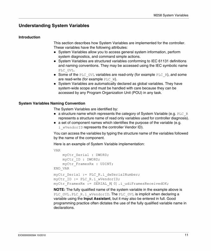
This section describes how System Variables are implemented for the controller. These variables have the following attributes:
System Variables allow you to access general system information, perform system diagnostics, and command simple actions.System Variables are structured variables conforming to IEC 61131 definitions and naming conventions. They may be accessed using the IEC symbolic name PLC_GVL.Some of the PLC_GVL variables are read-only (for example PLC_R), and some are read-write (for example PLC_W).System Variables are automatically declared as global variables. They have system-wide scope and must be handled with care because they can be accessed by any Program Organization Unit (POU) in any task.
System Variables Naming Convention
The System Variables are identified by:a structure name which represents the category of System Variable (e.g. PLC_R represents a structure name of read only variables used for controller diagnosis).a set of component names which identifies the purpose of the variable (e.g. i_wVendorID represents the controller Vendor ID).
You can access the variables by typing the structure name of the variables followed by the name of the component.
Here is an example of System Variable implementation:
VAR myCtr_Serial : DWORD; myCtr_ID : DWORD; myCtr_FramesRx : UDINT;END_VAR
myCtr_Serial := PLC_R.i_dwSerialNumber;myCtr_ID := PLC_R.i_wVendorID;myCtr_FramesRx := SERIAL_R[0].i_udiFramesReceivedOK;
NOTE: The fully qualified name of the system variable in the example above is PLC_GVL.PLC_R.i_wVendorID. The PLC_GVL is implicit when declaring a variable using the Input Assistant, but it may also be entered in full. Good programming practice often dictates the use of the fully qualified variable name in declarations.
EIO0000000584 10/2010 11
M258 System Variables
System Variables Location
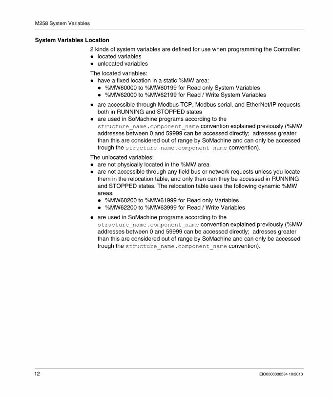
2 kinds of system variables are defined for use when programming the Controller:located variablesunlocated variables
The located variables:have a fixed location in a static %MW area:
%MW60000 to %MW60199 for Read only System Variables%MW62000 to %MW62199 for Read / Write System Variables
are accessible through Modbus TCP, Modbus serial, and EtherNet/IP requests both in RUNNING and STOPPED statesare used in SoMachine programs according to the structure_name.component_name convention explained previously (%MW addresses between 0 and 59999 can be accessed directly; adresses greater than this are considered out of range by SoMachine and can only be accessed trough the structure_name.component_name convention).
The unlocated variables:are not physically located in the %MW areaare not accessible through any field bus or network requests unless you locate them in the relocation table, and only then can they be accessed in RUNNING and STOPPED states. The relocation table uses the following dynamic %MW areas:
%MW60200 to %MW61999 for Read only Variables%MW62200 to %MW63999 for Read / Write Variables
are used in SoMachine programs according to the structure_name.component_name convention explained previously (%MW addresses between 0 and 59999 can be accessed directly; adresses greater than this are considered out of range by SoMachine and can only be accessed trough the structure_name.component_name convention).
12 EIO0000000584 10/2010

M258 System Variables
Using System Variables
Introduction
This topic describes the steps required to program and use System Variables in SoMachine.
System Variables can be used in all the Program Organization Units (POUs) of the application.
System Variables do not need to be declared in the GVL. They are automatically declared from the controller System Library.
Using System Variables in a POU
In the POU, start by entering the system variable structure name (PLC_R, PLC_W...) followed by a dot. The System Variables appear in the Input Assistant. You can select the desired variable or enter the full name manually.
NOTE: SoMachine has an auto completion feature. In the example above, once you have typed the structure name PLC_R., SoMachine offers a pop-up menu of possible component names/variables.
EIO0000000584 10/2010 13

M258 System Variables
Example
The following example shows the use of some System Variables:
VAR myCtr_Serial : DWORD; myCtr_ID : WORD; myCtr_FramesRx : UDINT;END_VAR
myCtr_Serial := PLC_R.i_dwSerialNumber;myCtr_ID := PLC_R.i_wVendorID;myCtr_FramesRx := SERIAL_R[0].i_udiFramesReceivedOK;
14 EIO0000000584 10/2010

M258 System Variables
1.2 PLC_R and PLC_W Structures
Overview
This section lists and describes the different System Variables included in the PLC_R and PLC_W structures.
What's in this Section?
This section contains the following topics:
Topic Page
PLC_R: Controller Read Only System Variables 16
PLC_W: Controller Read / Write System Variables 20
EIO0000000584 10/2010 15

M258 System Variables
PLC_R: Controller Read Only System Variables
Variable Structure
The following table describes the parameters of the PLC_R System Variable (PLC_R_STRUCT type):
%MW Var Name Type Comment
60000 i_wVendorID WORD Controller Vendor ID.101A hex = Schneider Electric
60001 i_wProductID WORD Controller Reference ID.NOTE: Vendor ID and Reference ID are the components of the Target ID of the Controller displayed in the Communication Settings view (Target ID = 101A XXXX hex).
60002 i_dwSerialNumber DWORD Controller Serial Number
60004 i_byFirmVersion[0..3] ARRAY[0..3] OF BYTE Controller Firmware Version [aa.bb.cc.dd]:
i_byFirmVersion[0] = aa...i_byFirmVersion[3] = dd
60006 i_byBootVersion[0..3] ARRAY[0..3] OF BYTE Controller Boot Version [aa.bb.cc.dd]:
i_byBootVersion[0] = aa...i_byBootVersion[3] = dd
60008 i_dwHardVersion DWORD Controller Hardware Version.
60010 i_dwChipVersion DWORD Controller Coprocessor Version.
60012 i_wStatus PLC_R_STATUS (see page 50)
State of the controller.
60013 i_wBootProjectStatus PLC_R_BOOT_PROJECT_STATUS (see page 48)
Returns information about the boot application stored in FLASH memory.
60014 i_wLastStopCause PLC_R_STOP_CAUSE (see page 51)
Cause of the last transition from RUN to another state.
60015 i_wLastApplicationError PLC_R_APPLICATION_ERROR (see page 47)
Cause of the last Controller Exception.
16 EIO0000000584 10/2010

M258 System Variables
60016 i_lwSystemFault_1 LWORD Bit field FFFF FFFF FFFF FFFF hex indicates no detected error.A bit at low level means that an error has been detected:
bit 0 = Embedded Expert detected error. See i_wIOStatus1 for diagnosticbit 1 = TM5 I/O detected error. See i_wIOStatus2 for diagnosticbit 2 = Ethernet 0 detected errorbit 3 = Serial 0 detected errorbit 4 = CAN 0 detected errorbit 5 = CAN 1 detected errorbit 6 = Interface bus Module 0 detected errorbit 7 = Interface bus Module 1 detected error
60020 i_lwSystemFault_2 LWORD Not used.
60024 i_wIOStatus1 PLC_R_IO_STATUS (see page 49)
Embedded Expert I/O status.
60025 i_wIOStatus2 PLC_R_IO_STATUS (see page 49)
TM5 I/O status.
60026 i_wClockBatteryStatus WORD Status of the Real Time Clock battery charge:
0000 hex = Battery charge is lowFFFF hex = Battery charge is okay
60028 i_dwAppliSignature1 DWORD 1st DWORD of 4 DWORD signature (16 bytes total).The Application Signature is generated by the software during build.
60030 i_dwAppliSignature2 DWORD 2nd DWORD of 4 DWORD signature (16 bytes total).The Application Signature is generated by the software during build.
%MW Var Name Type Comment
EIO0000000584 10/2010 17

M258 System Variables
60032 i_dwAppliSignature3 DWORD 3rd DWORD of 4 DWORD signature (16 bytes total).The Application Signature is generated by the software during build.
60034 i_dwAppliSignature4 DWORD 4th DWORD of 4 DWORD signature (16 bytes total).The Application Signature is generated by the software during build.
%MW Var Name Type Comment
n/a i_sVendorName STRING(31) Name of the vendor: “Schneider Electric”.
n/a i_sProductRef STRING(31) Reference of the Controller.
n/a i_sNodeName STRING(31) Node Name on SoMachine Network
n/a i_dwiLastStopTime DWORD The time of the last detected STOP in seconds beginning with January 1, 1970 at 00:00.
n/a i_dwLastPowerOffDate DWORD The date and time of the last detected power off in seconds beginning with January 1, 1970 at 00:00.NOTE: You can convert this value into date and time by using the function SysTimeRtcConvertUtcToDate. For more information about Time and Date conversion, refer to the Systime Library Guide (see SoMachine, Getting & Setting Real Time Clock, SysTime Library Guide).
n/a i_uiEventsCounter UINT Number of external events detected on inputs configured for external event detection since the last cold start.Reset by a Cold Start or by the PLC_W.q_wResetCounterEvent command.
n/a i_wTerminalPortStatus PLC_R_TERMINAL_PORT_STATUS (see page 52)
Status of the USB Programming Port (USB Mini-B).
n/a i_wUSBHostStatus PLC_R_USB_HOST_STATUS (see page 53)
Status of the USB Host port (USB A).
n/a i_wUsrFreeFileHdl WORD Number of File Handle free to open.A File Handle is the resources allocated by the system when you open a file.
n/a i_udiUsrFsTotalBytes UDINT User FileSystem total memory size (in bytes).It is the size of the flash memory for the directory "/usr/".
n/a i_udiUsrFsFreeBytes UDINT User FileSystem free memory size (in bytes).
18 EIO0000000584 10/2010

M258 System Variables
NOTE: n/a means that there is no predefined %MW mapping for this System Variable.
n/a i_uiTM5BusState UINT TM5 bus state BitField:bits 0..3 = not usedbit 4 = TM5 bus driver availablebit 5 = TM5 bus hardware foundbit 6 = TM5 bus configuration done successfullybits 7 = TM5 bus is operationalbits 8 = not usedbit 9 = error detected during TM5 bus configurationbit 10..15 = not used
n/a i_uiTM5SyncErrCnt UINT Number of invalid synchronous frames detected on TM5 bus. Reset with the PLC_W.q_wResetTM5Counters command and at Power Off.
n/a i_uiTM5AsynErrCnt UINT Number of invalid asynchronous frames detected on TM5 bus. Reset with the PLC_W.q_wResetTM5Counters command and at Power Off.
n/a i_uiTM5BreakCnt UINT Number of TM5 bus resets detected. Reset with the PLC_W.q_wResetTM5Counters command and at Power Off.
n/a i_uiTM5TopoChangedCnt UINT Number of changes in the TM5 bus topology. Reset with the PLC_W.q_wResetTM5Counters command and at Power Off.
n/a i_uiTM5BusCycleCnt UINT Number of TM5 bus cycles from Cold Start. Reset with the PLC_W.q_wResetTM5Counters command and at Power Off.
n/a i_wTM5BrokendownSlot WORD 00..FE hex = Slot number of an inoperative TM5 module.FF hex = All TM5 modules report they are operational.
EIO0000000584 10/2010 19

M258 System Variables
PLC_W: Controller Read / Write System Variables
Variable Structure
The following table describes the parameters of the PLC_W System Variable (PLC_W_STRUCT type):
NOTE: n/a means that there is no predefined %MW mapping for this System Variable.
%MW Var Name Type Comment
n/a q_wResetCounterEvent WORD Transition from 0 to 1 resets the events counter (PLC_R.i_uiEventsCounter).To reset the counter again, it is necessary to write this register to 0 before another transition from 0 to 1 can take place.
n/a q_wResetTM5counters WORD Transition from 0 to 1 resets all TM5 counters of PLC_R Structured System Variables (PLC_R.i_uiTM5SyncErrCnt to PLC_R.i_uiTM5BusCycleCnt)To reset the counters again, it is necessary to write this register to 0 before another transition from 0 to 1 can take place.
n/a q_uiOpenPLCControl UINT When Value pass from 0 to 6699, The command previously written in the following PLC_W.q_wPLCControl is executed.
n/a q_wPLCControl PLC_W_COMMAND (see page 54)
Controller RUN / STOP command executed when the system variable PLC_R.q_uiOpenPLCControl value pass from 0 to 6699.
20 EIO0000000584 10/2010
M258 System Variables
1.3 SERIAL_R and SERIAL_W Structures
Overview
This section lists and describes the different System Variables included in the SERIAL_R and SERIAL_W structures.
What's in this Section?
This section contains the following topics:
Topic Page
SERIAL_R[0..1]: Serial Line Read Only System Variables 22
SERIAL_W[0..1]: Serial Line Read / Write System Variables 23
EIO0000000584 10/2010 21

M258 System Variables
SERIAL_R[0..1]: Serial Line Read Only System Variables
Introduction
SERIAL_R is an array of 2 SERIAL_R_STRUCT type. Each element of the array returns diagnostic System Variables for the corresponding Serial Line.
For M258:Serial_R[0] refers to the Embedded Serial LineSerial_R[1] refers to the optional Serial Line PCI module if installed
Variable Structure
The following table describes the parameters of the SERIAL_R[0..1] System Variable:
NOTE: n/a means that there is no predefined %MW mapping for this System Variable.
NOTE:
The SERIAL_R Counters are reset on:Download.Controller Reset.SERIAL_W[x].q_wResetCounter command.Reset command by Modbus request function code #8.
%MW Var Name Type Comment
Serial Line
n/a i_udiFramesTransmittedOK UDINT Number of frames successfully transmitted.
n/a i_udiFramesReceivedOK UDINT Number of frames received without any detected errors.
n/a i_udiRX_MessagesError UDINT Number of frames received with detected errors (checksum, parity).
Modbus Specific
n/a i_uiSlaveExceptionCount UINT Number of Modbus exception responses returned by the Controller.
n/a i_udiSlaveMsgCount UINT Number of messages received from the Master and addressed to the Controller.
n/a i_uiSlaveNoRespCount UINT Number of Modbus Broadcast requests received by the Controller.
n/a i_uiSlaveNakCount UINT Not used
n/a i_uiSlaveBusyCount UINT Not used
n/a i_uiCharOverrunCount UINT Number of Character overrun.
22 EIO0000000584 10/2010

M258 System Variables
SERIAL_W[0..1]: Serial Line Read / Write System Variables
Introduction
SERIAL_W is an array of 2 SERIAL_W_STRUCT type. Each element of the array forces the SERIAL_R System Variables for the corresponding Serial Line to be reset.
For M258:Serial_W[0] refers to the Embedded Serial LineSerial_W[1] refers to the PCI Serial Line
Variable Structure
The following table describes the parameters of the SERIAL_W[0..1] System Variable:
NOTE: n/a means that there is no predefined %MW mapping for this System Variable.
%MW Var Name Type Comment
n/a q_wResetCounter WORD Transition from 0 to 1 resets all SERIAL_R[0..1] counters.To reset the counters again, it is necessary to write this register to 0 before another transition from 0 to 1 can take place.
EIO0000000584 10/2010 23
M258 System Variables
1.4 ETH_R and ETH_W Structures
Overview
This section lists and describes the different System Variables included in the ETH_R and ETH_W structures.
What's in this Section?
This section contains the following topics:
Topic Page
ETH_R: Ethernet Port Read Only System Variables 25
ETH_W: Ethernet Port Read / Write System Variables 29
24 EIO0000000584 10/2010

M258 System Variables
ETH_R: Ethernet Port Read Only System Variables
Variable Structure
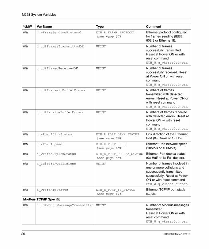
The following table describes the parameters of the ETH_R System Variable (ETH_R_STRUCT type):
%MW Var Name Type Comment
60050 i_byIPAddress[0..3] ARRAY[0..3] OF BYTE IP address [aaa.bbb.ccc.ddd]:
i_byIPAddress[0]= aaa...i_byIPAddress[3]= ddd
60052 i_bySubNetMask[0..3] ARRAY[0..3] OF BYTE Subnet Mask [aaa.bbb.ccc.ddd]:
i_bySub-netMask[0]= aaa...i_bySub-netMask[3]= ddd
60054 i_byGateway[0..3] ARRAY[0..3] OF BYTE Gateway address [aaa.bbb.ccc.ddd]:
i_byGateway[0]= aaa...i_byGateway[3]= ddd
60056 i_byMACAddress[0..5] ARRAY[0..5] OF BYTE MAC address [aa.bb.cc.dd.ee.ff]:
i_byMACAddress[0]= aa...i_byMACAddress[5]= ff
60059 i_sDeviceName STRING(16) Name used to get IP address from server.
n/a i_wIpMode ETH_R_IP_MODE (see page 56)
Method used to obtain an IP adress
n/a i_byFDRServerIPAddress[0..3] ARRAY[0..3] OF BYTE The IP address [aaa.bbb.ccc.ddd] of the DHCP or BootP server:
i_byFDRServerIPAddress[0]= aaa...i_byFDRServerIPAddress[3]= ddd
Equals 0.0.0.0 if Stored IP or Default IP used.
n/a i_udiOpenTcpConnections UDINT Number of open TCP connections.
EIO0000000584 10/2010 25
M258 System Variables
n/a i_wFrameSendingProtocol ETH_R_FRAME_PROTOCOL (see page 57)
Ethernet protocol configured for frames sending (IEEE 802.3 or Ethernet II).
n/a i_udiFramesTransmittedOK UDINT Number of frames successfully transmitted. Reset at Power ON or with reset command ETH_W.q_wResetCounter.
n/a i_udiFramedReceivedOK UDINT Number of frames successfully received. Reset at Power ON or with reset command ETH_W.q_wResetCounter.
n/a i_udiTransmitBufferErrors UDINT Numbers of frames transmitted with detected errors. Reset at Power ON or with reset command ETH_W.q_wResetCounter.
n/a i_udiReceiveBufferErrors UDINT Numbers of frames received with detected errors. Reset at Power ON or with reset command ETH_W.q_wResetCounter.
n/a i_wPortALinkStatus ETH_R_PORT_LINK_STATUS (see page 59)
Link direction of the Ethernet Port (0= Down or 1= Up).
n/a i_wPortASpeed ETH_R_PORT_SPEED (see page 60)
Ethernet Port network speed (10Mb/s or 100Mb/s).
n/a i_wPortADuplexStatus ETH_R_PORT_DUPLEX_STATUS (see page 58)
Ethernet Port duplex status (0= Half or 1= Full duplex).
n/a i_udiPortACollisions UDINT Number of frames involved in one or more collisions and subsequently transmitted successfully. Reset at Power ON or with reset command ETH_W.q_wResetCounter.
n/a i_wPortAIpStatus ETH_R_PORT_IP_STATUS (see page 61)
Ethernet TCP/IP port stack status.
Modbus TCP/IP Specific
n/a i_udiModbusMessageTransmitted UDINT Number of Modbus messages transmitted.Reset at Power ON or with reset command ETH_W.q_wResetCounter.
%MW Var Name Type Comment
26 EIO0000000584 10/2010

M258 System Variables
n/a i_udiModbusMessageReceived UDINT Number of Modbus messages received.Reset at Power ON or with reset command ETH_W.q_wResetCounter.
n/a i_udiModbusErrorMessage UDINT Modbus detected error messages transmitted and received.Reset at Power ON or with reset command ETH_W.q_wResetCounter.
n/a i_byMasterIpTimeouts BYTE Ethernet Modbus TCP Master timeout events counter.Reset at Power ON or with reset command ETH_W.q_wResetCounter.
n/a i_byMasterIpLost BYTE Ethernet Modbus TCP Master link status: 0 = link OK, 1 = link lost.
%MW Var Name Type Comment
EtherNet/IP Specific
n/a i_udiETHIP_IOMessagingTransmitted UDINT EtherNet/IP Class 1 frames transmitted.Reset at Power ON or with reset command ETH_W.q_wResetCounter.
n/a i_udiETHIP_IOMessagingReceived UDINT EtherNet/IP Class 1 frames received.Reset at Power ON or with reset command ETH_W.q_wResetCounter.
n/a i_udiUCMM_Request UDINT EtherNet/IP Unconnected Messages received.Reset at Power ON or with reset command ETH_W.q_wResetCounter.
n/a i_udiUCMM_Error UDINT EtherNet/IP invalid Unconnected Messages received.Reset at Power ON or with reset command ETH_W.q_wResetCounter.
EIO0000000584 10/2010 27

M258 System Variables
NOTE: n/a means that there is no predefined %MW mapping for this System Variable.
n/a i_udiClass3_Request UDINT EtherNet/IP Class 3 requests received.Reset at Power ON or with reset command ETH_W.q_wResetCounter.
n/a i_udiClass3_Error UDINT EtherNet/IP invalid class 3 requests received.Reset at Power ON or with reset command ETH_W.q_wResetCounter.
n/a i_uiAssemblyInstanceInput UINT Input Assembly Instance number. See the appropriate Programming Guide for your controller for more informatrion.
n/a i_uiAssemblyInstanceInputSize UINT Input Assembly Instance size. See the appropriate Programming Guide for your controller for more informatrion.
n/a i_uiAssemblyInstanceOutput UINT Output Assembly Instance number. See the appropriate Programming Guide for your controller for more informatrion.
n/a i_uiAssemblyInstanceOutputSize UINT Output Assembly Instance size. See the appropriate Programming Guide for your controller for more informatrion.
n/a i_uiETHIP_ConnectionTimeouts UINT Number of connection timeouts. Reset at Power ON or with reset command ETH_W.q_wResetCounter.
n/a i_ucEipRunldle ETH_R_RUN_IDLE (see page 62)
Run (value=1)/Idle(value=0) flag for EtherNet/IP class 1 connection.
28 EIO0000000584 10/2010
M258 System Variables
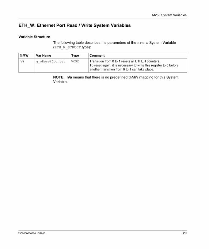
ETH_W: Ethernet Port Read / Write System Variables
Variable Structure
The following table describes the parameters of the ETH_W System Variable (ETH_W_STRUCT type):
NOTE: n/a means that there is no predefined %MW mapping for this System Variable.
%MW Var Name Type Comment
n/a q_wResetCounter WORD Transition from 0 to 1 resets all ETH_R counters.To reset again, it is necessary to write this register to 0 before another transition from 0 to 1 can take place.
EIO0000000584 10/2010 29

M258 System Variables
1.5 TM5_MODULE_R Structure
TM5_MODULE_R[1..254]: TM5 Modules Read Only System Variables
Introduction
TM5_MODULE_R is an array of 254 TM5_MODULE_R_STRUCT type. Each element of the array returns diagnostic System Variables for the corresponding TM5 Module.
For M258:TM5_MODULE_R[1] refer to the TM5 Module 1...TM5_MODULE_R[254] refer to the TM5 Module 254
Variable Structure
The following table describes the parameters of the TM5_MODULE_R[1..254] System Variable:
NOTE: n/a means that there is no predefined %MW mapping for this System Variable.
%MW Var Name Type Comment
n/a i_wVendorID WORD TM5 Module Vendor ID of the target.
n/a i_wProductID WORD TM5 Module Type ID of the target.
n/a i_dwSerialNumber DWORD TM5 Module Serial Number.
n/a i_wFirmVersion WORD TM5 Module Firmware version.
n/a i_wBootVersion WORD TM5 Module Boot version.
n/a i_wModuleState TM5_MODULE_STATE (see page 63)
Describes the state of the TM5 module. The module is operational when TM5_ACTIVE is returned.
30 EIO0000000584 10/2010

EIO0000000584 10/2010
2
M258 System Functions
EIO0000000584 10/2010
M258 System Functions
Overview
This chapter describes the functions included in the M258 PLCSystem library.
What's in this Chapter?
This chapter contains the following sections:
Section Topic Page
2.1 M258 Read Functions 32
2.2 M258 Write Functions 40
31

M258 System Functions
2.1 M258 Read Functions
Overview
This section describes the read functions included in the M258 PLCSystem library.
What's in this Section?
This section contains the following topics:
Topic Page
DM72FGetImmediateInput: Read Input of an Embedded Expert I/O 33
getTM5Delay: Number of TM5 bus cycles without valid exchange 34
IsFirstMastColdCycle: Indicates if Cycle is the First MAST Cold Start Cycle 36
IsFirstMastCycle: Indicates if Cycle is the First MAST Cycle 37
IsFirstMastWarmCycle: Indicates if Cycle is the First MAST Warm Start Cycle 39
32 EIO0000000584 10/2010

M258 System Functions
DM72FGetImmediateInput: Read Input of an Embedded Expert I/O
Function Description
This function is applicable to the Embedded Expert I/O Block DM72F0 and DM72F1. It returns the current physical value of the input, which may be different from the current logical value of that input. The value of the variable for that input does not change until the next bus cycle.
Graphical Representation
IL and ST Representation
To see the general representation in IL or ST language, refer to the chapter Function and Function Block Representation (see page 75).
I/O Variable Description
The following table describes the input variables:
The following table describes the output variables
Input Type Comment
Block INT Targeted block:0= DM72F01= DM72F1
Input INT Targeted input of the block.0..6= DI0..DI6
Output Type Comment
DM72FGetImmediateInput BOOL Value of the input <Input> of the block <block>= FALSE/TRUE.
Error BOOL FALSE= operation is okay.TRUE= detected operation error, the function returns an invalid value.
ErrID IMMEDIATE_FUNC_ERR_TYPE Detected operation error code when Error is TRUE.
EIO0000000584 10/2010 33

M258 System Functions
getTM5Delay: Number of TM5 bus cycles without valid exchange
Function Description
This function will return the number of TM5 bus cycles without valid exchange with a targeted TM5 module.
NOTE: For TM5 module diagnostic, see System Variable TM5_MODULE_R (see page 30).
Graphical Representation
IL and ST Representation
To see the general representation in IL or ST language, refer to the chapter Function and Function Block Representation (see page 75).
I/O Variable Description
The following table describes the input variables:
The following table describes the output variables
Input Type Comment
NodeId DINT Targeted TM5 Module NodeNumber (to get the NodeNumber, check the value in the TM5 Module editor under the IO Conf screen).
Output Type Comment
getTM5Delay USINT The variable can take the following values:0= OK[1..3]= 1 to 3 cycles without valid exchange]-1= more than 3 cycles without valid exchange or invalid parameter
34 EIO0000000584 10/2010
M258 System Functions
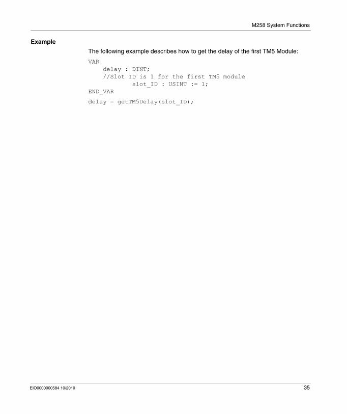
Example
The following example describes how to get the delay of the first TM5 Module:
VAR delay : DINT; //Slot ID is 1 for the first TM5 module slot_ID : USINT := 1;END_VAR
delay = getTM5Delay(slot_ID);
EIO0000000584 10/2010 35

M258 System Functions
IsFirstMastColdCycle: Indicates if Cycle is the First MAST Cold Start Cycle
Function Description
This function returns TRUE during the 1st MAST cycle after a cold start (first cycle after download or reset cold).
Graphical Representation
IL and ST Representation
To see the general representation in IL or ST language, refer to the chapter Function and Function Block Representation (see page 75).
I/O Variable Description
The following table describes the output variable:
Example
Refer to the function IsFirstMastCycle (see page 37).
Output Type Comment
IsFirstMastColdCycle BOOL TRUE during the first MAST task cycle after a cold start.
36 EIO0000000584 10/2010
M258 System Functions
IsFirstMastCycle: Indicates if Cycle is the First MAST Cycle
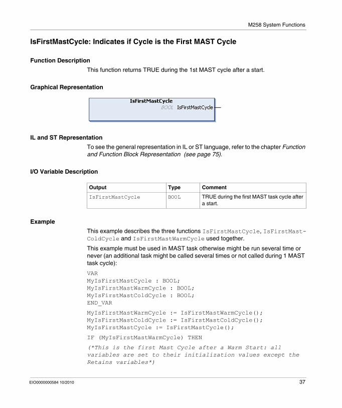
Function Description
This function returns TRUE during the 1st MAST cycle after a start.
Graphical Representation
IL and ST Representation
To see the general representation in IL or ST language, refer to the chapter Function and Function Block Representation (see page 75).
I/O Variable Description
Example
This example describes the three functions IsFirstMastCycle, IsFirstMast-ColdCycle and IsFirstMastWarmCycle used together.
This example must be used in MAST task otherwise might be run several time or never (an additional task might be called several times or not called during 1 MAST task cycle):
VARMyIsFirstMastCycle : BOOL;MyIsFirstMastWarmCycle : BOOL;MyIsFirstMastColdCycle : BOOL;END_VAR
MyIsFirstMastWarmCycle := IsFirstMastWarmCycle();MyIsFirstMastColdCycle := IsFirstMastColdCycle();MyIsFirstMastCycle := IsFirstMastCycle();
IF (MyIsFirstMastWarmCycle) THEN
(*This is the first Mast Cycle after a Warm Start: all variables are set to their initialization values except the Retains variables*)
Output Type Comment
IsFirstMastCycle BOOL TRUE during the first MAST task cycle after a start.
EIO0000000584 10/2010 37

M258 System Functions
(*=> initialize the needed variables in order your application to run as expected in this case*)
END_IF;
IF (MyIsFirstMastColdCycle) THEN
(*This is the first Mast Cycle after a Cold Start: all variables are set to their initialization values including the Retains Variables*)
(*=> initialize the needed variables in order your application to run as expected in this case*)
END_IF;
IF (MyIsFirstMastCycle) THEN
(*This is the first Mast Cycle after a Start, i.e. after a Warm or Cold Start as well as STOP/RUN commands*)
(*=> initialize the needed variables in order your application to run as expected in this case*)
END_IF;
38 EIO0000000584 10/2010
M258 System Functions
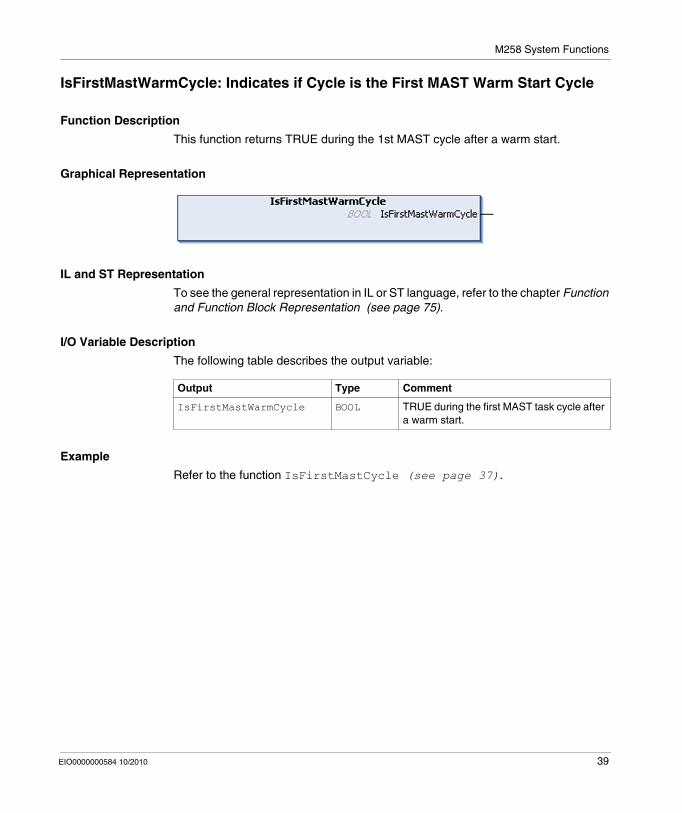
IsFirstMastWarmCycle: Indicates if Cycle is the First MAST Warm Start Cycle
Function Description
This function returns TRUE during the 1st MAST cycle after a warm start.
Graphical Representation
IL and ST Representation
To see the general representation in IL or ST language, refer to the chapter Function and Function Block Representation (see page 75).
I/O Variable Description
The following table describes the output variable:
Example
Refer to the function IsFirstMastCycle (see page 37).
Output Type Comment
IsFirstMastWarmCycle BOOL TRUE during the first MAST task cycle after a warm start.
EIO0000000584 10/2010 39

M258 System Functions
2.2 M258 Write Functions
Overview
This section describes the write functions included in the M258 PLCSystem library.
What's in this Section?
This section contains the following topics:
Topic Page
SetLEDBehaviour: Determines the Behavior of a LED 41
SetRTCDrift: Adjust the Real Time Clock Each Week 43
40 EIO0000000584 10/2010

M258 System Functions
SetLEDBehaviour: Determines the Behavior of a LED
Function Description
This function controls the diagnostic LEDs APP0 and APP1.
The following figure shows the LEDs on the front panel display:
Graphical Representation
IL and ST Representation
To see the general representation in IL or ST language, refer to the chapter Function and Function Block Representation (see page 75).
I/O Variables Description
The following table describes the input parameters:
The following table describes the output variable:
MS
Eth NS
BATTERY
APP1APP0
Eth LAEth ST
USB HostMBS COMCAN0 STS
Inputs Type Comment
LedId LED_ID (see page 65)
ID of the application LED.
LedColor LED_COLOR (see page 68)
Color of the application LED.
LedBhv LED_BHV (see page 66)
Mode of the application LED.
Output Type Comment
SetLEDBehaviour LED_BHV_ERROR (see page 67)
Returns NO_ERROR (00 hex) if command is okay otherwise returns the ID code of the detected error.
EIO0000000584 10/2010 41

M258 System Functions
Example
This example shows how to command LED APP0 to illuminate green:
VAR myLEDStatus : LED_BHV_ERROR; myLED : LED_ID := LED_0; myLEDColor : LED_COLOR := LED_GREEN; myLEDMode : LED_BHV := LED_ON;END_VAR
myLEDStatus := SetLedBehaviour(myLED, myLEDColor, myLEDMode);
NOTE: LED colors are controlled separately and can be mixed, therefor turn off the current color before lighting the new one. The table below shows an example of SetLedBehaviour commands sequence with associated LED behaviour:
step LedId LedColor LedBhv GREEN flashing mode
RED flashing mode
1 LED_0 - - OFF OFF
2 LED_0 LED_GREEN LED_ON ON OFF
3 LED_0 LED_GREEN LED_OFF OFF OFF
4 LED_0 LED_RED LED_ON OFF ON
42 EIO0000000584 10/2010

M258 System Functions
SetRTCDrift: Adjust the Real Time Clock Each Week
Function Description
This function adds or subtracts to the Real Time Clock a specified amount of seconds, each week, at the specified day of the week, hour:minute
NOTE: The SetRTCDrift function needs to be programmed to be executed only during the First Mast Cycle.
Graphical Representation
IL and ST Representation
To see the general representation in IL or ST language, refer to the chapter Function and Function Block Representation (see page 75).
I/O Variables Description
The following table describes the input parameters:
NOTE: If the values entered for RTCDrift, Day, Hour, Minute exceed the limit values, the controller Firmware will set all values to their maximum values.
The following table describes the output variable:
Inputs Type Comment
RTCDrift SINT(-29..29) Correction in seconds (-29 ... +29)
Day DAY_OF_WEEK (see page 70)
Day of the week the day will be executed.
Hour HOUR (see page 71) Hour of change.
Minute MINUTE (see page 72) Minute of change.
Output Type Comment
SetRTCDrift RTCSETDRIFT_ERROR (see page 69)
Returns RTC_OK (00 hex) if command is okay otherwise returns the ID code of the detected error.
EIO0000000584 10/2010 43

M258 System Functions
Example
In this example, the function is called only once during the first MAST task cycle, 20 seconds is added to the RTC every Tuesday at 5:45 a.m.:
VAR MyRTCDrift : SINT (-29..29) := 0; MyDay : DAY_OF_WEEK; MyHour : HOUR; MyMinute : MINUTE;END_VAR
IF IsFirstMastCycle() THEN MyRTCDrift := 20; MyDay := TUESDAY; MyHour := 5; MyMinute := 45; SetRTCDrift(MyRTCDrift, MyDay, MyHour, MyMinute);END_IF
44 EIO0000000584 10/2010
EIO0000000584 10/2010
3
M258 PLC System Library Data Types
EIO0000000584 10/2010
M258 PLCSystem Library Data Types
Overview
This chapter describes the DataTypes of the M258 PLCSystem Library.
Two kinds of Data Types are available:System Variable Data types are used by the System Variables (see page 9) of the M258 PLCSystem Library (PLC_R, PLC_W,...).System Function Data Types are used by the read/write System Functions (see page 31) of the M258 PLCSystem Library.
What's in this Chapter?
This chapter contains the following sections:
Section Topic Page
3.1 PLC_R/W System Variables Data Types 46
3.2 ETH_R/W System Variables Data Types 55
3.3 TM5_MODULE_R/W System Variables Data Types 63
3.4 System Functions Data Types 64
45
M258 PLC System Library Data Types
3.1 PLC_R/W System Variables Data Types
Overview
This section lists and describes the System Variables Data Types included in the PLC_R and PLC_W structures.
What's in this Section?
This section contains the following topics:
Topic Page
PLC_R_APPLICATION_ERROR: Detected Application Error Status Codes 47
PLC_R_BOOT_PROJECT_STATUS: Boot Project Status Codes 48
PLC_R_IO_STATUS: I/O Status Codes 49
PLC_R_STATUS: Controller Status Codes 50
PLC_R_STOP_CAUSE: RUN to Other State Transition Cause Codes 51
PLC_R_TERMINAL_PORT_STATUS: Programming Port Connection Status Codes
52
PLC_R_USB_HOST_STATUS: USB Host Port Connection Status Codes 53
PLC_W_COMMAND: Control Command Codes 54
46 EIO0000000584 10/2010
M258 PLC System Library Data Types
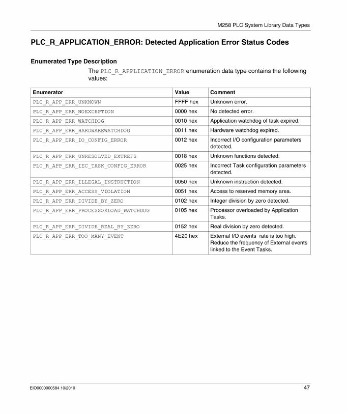
PLC_R_APPLICATION_ERROR: Detected Application Error Status Codes
Enumerated Type Description
The PLC_R_APPLICATION_ERROR enumeration data type contains the following values:
Enumerator Value Comment
PLC_R_APP_ERR_UNKNOWN FFFF hex Unknown error.
PLC_R_APP_ERR_NOEXCEPTION 0000 hex No detected error.
PLC_R_APP_ERR_WATCHDOG 0010 hex Application watchdog of task expired.
PLC_R_APP_ERR_HARDWAREWATCHDOG 0011 hex Hardware watchdog expired.
PLC_R_APP_ERR_IO_CONFIG_ERROR 0012 hex Incorrect I/O configuration parameters detected.
PLC_R_APP_ERR_UNRESOLVED_EXTREFS 0018 hex Unknown functions detected.
PLC_R_APP_ERR_IEC_TASK_CONFIG_ERROR 0025 hex Incorrect Task configuration parameters detected.
PLC_R_APP_ERR_ILLEGAL_INSTRUCTION 0050 hex Unknown instruction detected.
PLC_R_APP_ERR_ACCESS_VIOLATION 0051 hex Access to reserved memory area.
PLC_R_APP_ERR_DIVIDE_BY_ZERO 0102 hex Integer division by zero detected.
PLC_R_APP_ERR_PROCESSORLOAD_WATCHDOG 0105 hex Processor overloaded by Application Tasks.
PLC_R_APP_ERR_DIVIDE_REAL_BY_ZERO 0152 hex Real division by zero detected.
PLC_R_APP_ERR_TOO_MANY_EVENT 4E20 hex External I/O events rate is too high. Reduce the frequency of External events linked to the Event Tasks.
EIO0000000584 10/2010 47

M258 PLC System Library Data Types
PLC_R_BOOT_PROJECT_STATUS: Boot Project Status Codes
Enumerated Type Description
The PLC_R_BOOT_PROJECT_STATUS enumeration data type contains the following values:
Enumerator Value Comment
PLC_R_NO_BOOT_PROJECT 0000 hex Boot project does not exist in Flash memory.
PLC_R_BOOT_PROJECT_CREATION_IN_PROGRESS 0001 hex Boot project is being created.
PLC_R_DIFFERENT_BOOT_PROJECT 0002 hex Boot project in Flash is different from the project loaded in RAM.
PLC_R_VALID_BOOT_PROJECT FFFF hex Boot project in Flash is the same as the project loaded in RAM.
48 EIO0000000584 10/2010
M258 PLC System Library Data Types
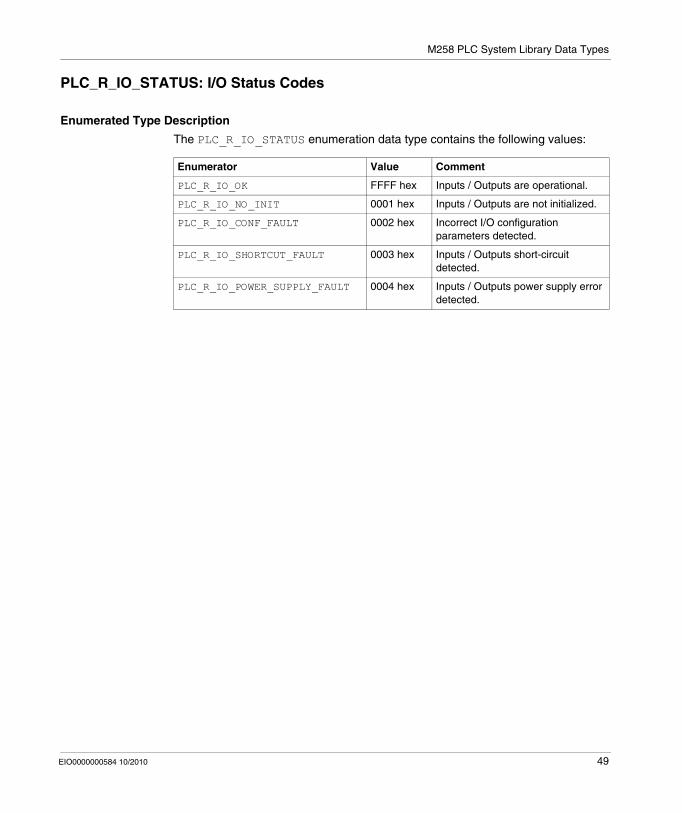
PLC_R_IO_STATUS: I/O Status Codes
Enumerated Type Description
The PLC_R_IO_STATUS enumeration data type contains the following values:
Enumerator Value Comment
PLC_R_IO_OK FFFF hex Inputs / Outputs are operational.
PLC_R_IO_NO_INIT 0001 hex Inputs / Outputs are not initialized.
PLC_R_IO_CONF_FAULT 0002 hex Incorrect I/O configuration parameters detected.
PLC_R_IO_SHORTCUT_FAULT 0003 hex Inputs / Outputs short-circuit detected.
PLC_R_IO_POWER_SUPPLY_FAULT 0004 hex Inputs / Outputs power supply error detected.
EIO0000000584 10/2010 49
M258 PLC System Library Data Types
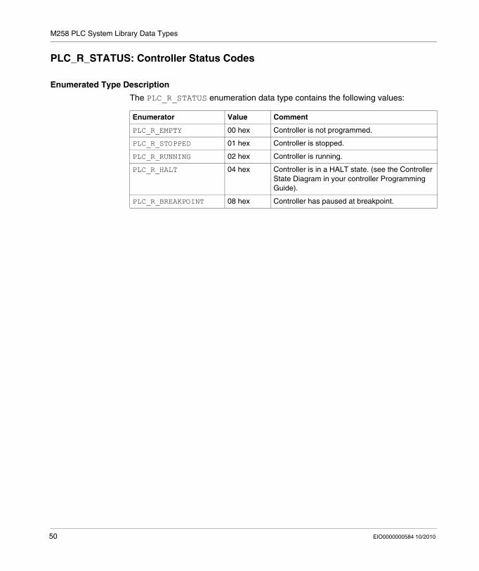
PLC_R_STATUS: Controller Status Codes
Enumerated Type Description
The PLC_R_STATUS enumeration data type contains the following values:
Enumerator Value Comment
PLC_R_EMPTY 00 hex Controller is not programmed.
PLC_R_STOPPED 01 hex Controller is stopped.
PLC_R_RUNNING 02 hex Controller is running.
PLC_R_HALT 04 hex Controller is in a HALT state. (see the Controller State Diagram in your controller Programming Guide).
PLC_R_BREAKPOINT 08 hex Controller has paused at breakpoint.
50 EIO0000000584 10/2010
M258 PLC System Library Data Types
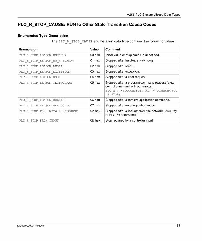
PLC_R_STOP_CAUSE: RUN to Other State Transition Cause Codes
Enumerated Type Description
The PLC_R_STOP_CAUSE enumeration data type contains the following values:
Enumerator Value Comment
PLC_R_STOP_REASON_UNKNOWN 00 hex Initial value or stop cause is undefined.
PLC_R_STOP_REASON_HW_WATCHDOG 01 hex Stopped after hardware watchdog.
PLC_R_STOP_REASON_RESET 02 hex Stopped after reset.
PLC_R_STOP_REASON_EXCEPTION 03 hex Stopped after exception.
PLC_R_STOP_REASON_USER 04 hex Stopped after a user request.
PLC_R_STOP_REASON_IECPROGRAM 05 hex Stopped after a program command request (e.g.: control command with parameter PLC_W.q_wPLCControl:=PLC_W_COMMAND.PLC_W_STOP;).
PLC_R_STOP_REASON_DELETE 06 hex Stopped after a remove application command.
PLC_R_STOP_REASON_DEBUGGING 07 hex Stopped after entering debug mode.
PLC_R_STOP_FROM_NETWORK_REQUEST 0A hex Stopped after a request from the network (USB key or PLC_W command).
PLC_R_STOP_FROM_INPUT 0B hex Stop required by a controller input.
EIO0000000584 10/2010 51
M258 PLC System Library Data Types
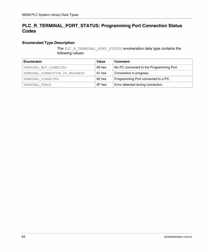
PLC_R_TERMINAL_PORT_STATUS: Programming Port Connection Status Codes
Enumerated Type Description
The PLC_R_TERMINAL_PORT_STATUS enumeration data type contains the following values:
Enumerator Value Comment
TERMINAL_NOT_CONNECTED 00 hex No PC connected to the Programming Port.
TERMINAL_CONNECTION_IN_PROGRESS 01 hex Connection in progress.
TERMINAL_CONNECTED 02 hex Programming Port connected to a PC.
TERMINAL_ERROR 0F hex Error detected during connection.
52 EIO0000000584 10/2010

M258 PLC System Library Data Types
PLC_R_USB_HOST_STATUS: USB Host Port Connection Status Codes
Enumerated Type Description
The PLC_R_USB_HOST_STATUS enumeration data type contains the following values:
Enumerator Value Comment
USB_NOT_CONNECTED 00 hex No device (Memory Key) connected to the USB Host Port.
USB_CONNECTION_IN_PROGRESS 01 hex Connection in progress.
USB_CONNECTED 02 hex USB Host port connected to a device (Memory Key).
USB_ERROR 0F hex Error detected during connection.
EIO0000000584 10/2010 53

M258 PLC System Library Data Types
PLC_W_COMMAND: Control Command Codes
Enumerated Type Description
The PLC_W_COMMAND enumeration data type contains the following values:
Enumerator Value Comment
PLC_W_STOP 01 hex Command to stop the controller.
PLC_W_RUN 02 hex Command to run the controller.
PLC_W_RESET_COLD 04 hex Command to initiate a Controller cold reset.
PLC_W_RESET_WARM 08 hex Command to initiate a Controller warm reset.
54 EIO0000000584 10/2010

M258 PLC System Library Data Types
3.2 ETH_R/W System Variables Data Types
Overview
This section lists and describes the System Data Types included in the ETH_R and ETH_W structures.
What's in this Section?
This section contains the following topics:
Topic Page
ETH_R_IP_MODE: IP Address Source Codes 56
ETH_R_FRAME_PROTOCOL: Frame Transmission Protocol Codes 57
ETH_R_PORT_DUPLEX_STATUS: Transmission Mode Codes 58
ETH_R_PORT_LINK_STATUS: Communication Link Direction Codes 59
ETH_R_PORT_SPEED: Communication Speed of the Ethernet Port Codes 60
ETH_R_PORT_IP_STATUS: Ethernet TCP/IP Port Status Codes 61
ETH_R_RUN_IDLE: Ethernet/IP Run and Idle States Codes 62
EIO0000000584 10/2010 55
M258 PLC System Library Data Types
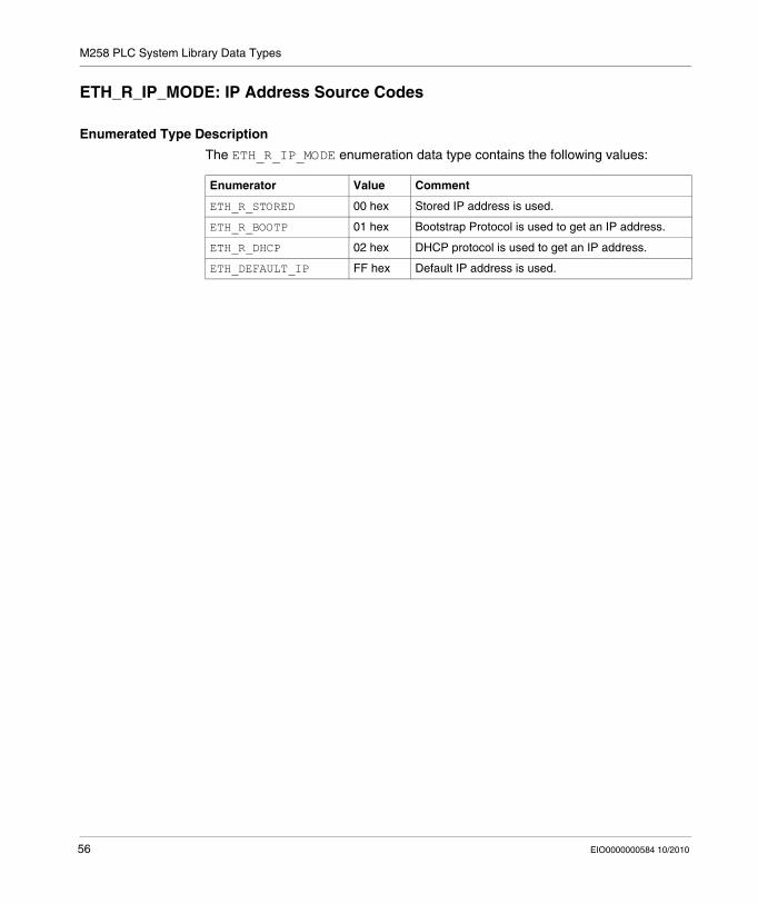
ETH_R_IP_MODE: IP Address Source Codes
Enumerated Type Description
The ETH_R_IP_MODE enumeration data type contains the following values:
Enumerator Value Comment
ETH_R_STORED 00 hex Stored IP address is used.
ETH_R_BOOTP 01 hex Bootstrap Protocol is used to get an IP address.
ETH_R_DHCP 02 hex DHCP protocol is used to get an IP address.
ETH_DEFAULT_IP FF hex Default IP address is used.
56 EIO0000000584 10/2010

M258 PLC System Library Data Types
ETH_R_FRAME_PROTOCOL: Frame Transmission Protocol Codes
Enumerated Type Description
The ETH_R_FRAME_PROTOCOL enumeration data type contains the following values:
Enumerator Value Comment
ETH_R_802_3 00 hex The protocol used for frame transmission is 802.3.
ETH_R_ETHERNET_II 01 hex The protocol used for frame transmission is Ethernet II.
EIO0000000584 10/2010 57

M258 PLC System Library Data Types
ETH_R_PORT_DUPLEX_STATUS: Transmission Mode Codes
Enumerated Type Description
The ETH_R_PORT_DUPLEX_STATUS enumeration data type contains the following values:
Enumerator Value Comment
ETH_R_PORT_HALF_DUPLEX 00 hex Half duplex transmission mode is used.
ETH_R_FULL_DUPLEX 01 hex Full duplex transmission mode is used.
58 EIO0000000584 10/2010

M258 PLC System Library Data Types
ETH_R_PORT_LINK_STATUS: Communication Link Direction Codes
Enumerated Type Description
The ETH_R_PORT_LINK_STATUS enumeration data type contains the following values:
Enumerator Value Comment
ETH_R_LINK_DOWN 00 hex Communication link from server to device.
ETH_R_LINK_UP 01 hex Communication link from device to server.
EIO0000000584 10/2010 59

M258 PLC System Library Data Types
ETH_R_PORT_SPEED: Communication Speed of the Ethernet Port Codes
Enumerated Type Description
The ETH_R_PORT_SPEED enumeration data type contains the following values:
Enumerator Value Comment
ETH_R_SPEED_10_MB 10 dec Network speed is 10 megabits per second.
ETH_R_100_MB 100 dec Network speed is 100 megabits per second.
60 EIO0000000584 10/2010
M258 PLC System Library Data Types
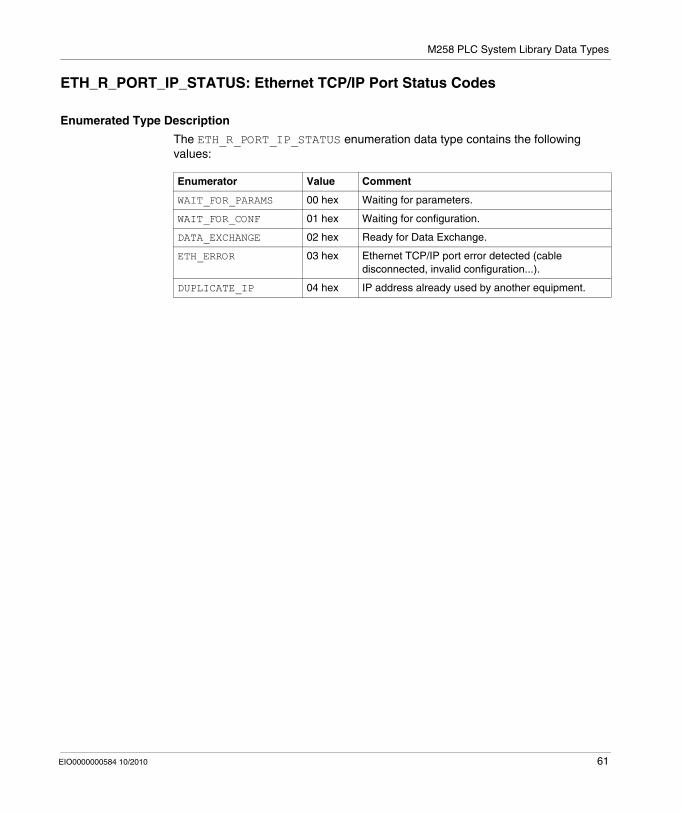
ETH_R_PORT_IP_STATUS: Ethernet TCP/IP Port Status Codes
Enumerated Type Description
The ETH_R_PORT_IP_STATUS enumeration data type contains the following values:
Enumerator Value Comment
WAIT_FOR_PARAMS 00 hex Waiting for parameters.
WAIT_FOR_CONF 01 hex Waiting for configuration.
DATA_EXCHANGE 02 hex Ready for Data Exchange.
ETH_ERROR 03 hex Ethernet TCP/IP port error detected (cable disconnected, invalid configuration...).
DUPLICATE_IP 04 hex IP address already used by another equipment.
EIO0000000584 10/2010 61
M258 PLC System Library Data Types
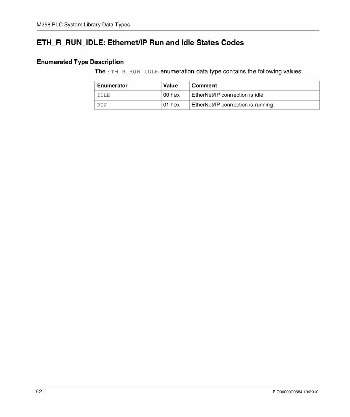
ETH_R_RUN_IDLE: Ethernet/IP Run and Idle States Codes
Enumerated Type Description
The ETH_R_RUN_IDLE enumeration data type contains the following values:
Enumerator Value Comment
IDLE 00 hex EtherNet/IP connection is idle.
RUN 01 hex EtherNet/IP connection is running.
62 EIO0000000584 10/2010

M258 PLC System Library Data Types
3.3 TM5_MODULE_R/W System Variables Data Types
TM5_MODULE_STATE: TM5 Expansion Module Status Codes
Enumerated Type Description
The TM5_MODULE_STATE enumeration data type contains the following values:
Enumerator Value Comment
TM5_INACTIVE 00 hex State machine inactive.
TM5_BOOT 0A hex Boot in progress.
TM5_FWDNLD 0B hex Firmware download in progress.
TM5_PREOP 14 hex Basic initialization.
TM5_OPERATE 1E hex Register initialization.
TM5_ACTIVE 64 hex Module communication is active.
TM5_ERROR C8 hex Module in Detected Error state.
TM5_UNSUP C9 hex TM5 Module not supported.
TM5_NOCFG CA hex No configuration available.
EIO0000000584 10/2010 63

M258 PLC System Library Data Types
3.4 System Functions Data Types
Overview
This section describes the different System Function Data Types of the M258 PLCSystem library.
What's in this Section?
This section contains the following topics:
Topic Page
LED_ID: SetLEDBehaviour Function LedId Parameter Codes 65
LED_BHV: SetLEDBehaviour Function LedBhv Parameter Codes 66
LED_BHV_ERROR: Detected SetLEDBehaviour Function Error Codes 67
LED_COLOR: SetLEDBehaviour Function LedColor Parameter Codes 68
RTCSETDRIFT_ERROR: Detected SetRTCDrift Function Error Codes 69
DAY_OF_WEEK: SetRTCDrift Function Day Parameter Codes 70
HOUR: SetRTCDrift Function Hour Parameter Type 71
MINUTE: SetRTCDrift Function Minute Parameter Type 72
64 EIO0000000584 10/2010
M258 PLC System Library Data Types
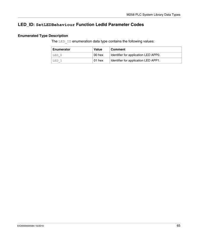
LED_ID: SetLEDBehaviour Function LedId Parameter Codes
Enumerated Type Description
The LED_ID enumeration data type contains the following values:
Enumerator Value Comment
LED_0 00 hex Identifier for application LED APP0.
LED_1 01 hex Identifier for application LED APP1.
EIO0000000584 10/2010 65
M258 PLC System Library Data Types
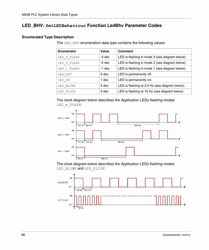
LED_BHV: SetLEDBehaviour Function LedBhv Parameter Codes
Enumerated Type Description
The LED_BHV enumeration data type contains the following values:
The clock diagram below describes the Application LEDs flashing modes LED_x_FLASH:
The clock diagram below describes the Application LEDs flashing modes LED_BLINK and LED_FLICK:
Enumerator Value Comment
LED_3_FLASH -3 dec LED is flashing in mode 3 (see diagram below).
LED_2_FLASH -2 dec LED is flashing in mode 2 (see diagram below).
LED_1_FLASH -1 dec LED is flashing in mode 1 (see diagram below).
LED_OFF 0 dec LED is permanently off.
LED_ON 1 dec LED is permanently on.
LED_BLINK 2 dec LED is flashing at 2.5 Hz (see diagram below).
LED_FLICK 3 dec LED is flashing at 10 Hz (see diagram below).
66 EIO0000000584 10/2010

M258 PLC System Library Data Types
LED_BHV_ERROR: Detected SetLEDBehaviour Function Error Codes
Enumerated Type Description
The LED_BHV_ERROR enumeration data type contains the following values:
Enumerator Value Comment
NO_ERROR 00 hex LED behavior setting function executed without detected error.
UNKNOWN_LED 01 hex LED_ID parameter is unknown.
UNKNOWN_COLOR 02 hex LED_COLOR parameter is unknown.
UNKNOWN_STATE 03 hex LED status, as contained in LED_BHV parameter is unknown.
FIRMWARE_ERROR 04 hex Command rejected by FW on detected error.
EIO0000000584 10/2010 67

M258 PLC System Library Data Types
LED_COLOR: SetLEDBehaviour Function LedColor Parameter Codes
Enumerated Type Description
The LED_COLOR enumeration data type contains the following values:
Enumerator Value Comment
LED_RED 00 hex LED color is red.
LED_GREEN 01 hex LED color is green.
68 EIO0000000584 10/2010
M258 PLC System Library Data Types
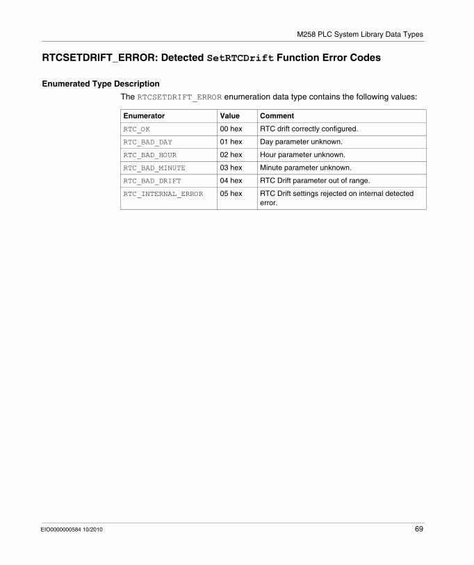
RTCSETDRIFT_ERROR: Detected SetRTCDrift Function Error Codes
Enumerated Type Description
The RTCSETDRIFT_ERROR enumeration data type contains the following values:
Enumerator Value Comment
RTC_OK 00 hex RTC drift correctly configured.
RTC_BAD_DAY 01 hex Day parameter unknown.
RTC_BAD_HOUR 02 hex Hour parameter unknown.
RTC_BAD_MINUTE 03 hex Minute parameter unknown.
RTC_BAD_DRIFT 04 hex RTC Drift parameter out of range.
RTC_INTERNAL_ERROR 05 hex RTC Drift settings rejected on internal detected error.
EIO0000000584 10/2010 69

M258 PLC System Library Data Types
DAY_OF_WEEK: SetRTCDrift Function Day Parameter Codes
Enumerated Type Description
The enumeration data type contains the following values:
Enumerator Value Comment
MONDAY 01 hex Set the day of week to Monday
TUESDAY 02 hex Set the day of week to Tuesday
WEDNESDAY 03 hex Set the day of week to Wednesday
THURSDAY 04 hex Set the day of week to Thursday
FRIDAY 05 hex Set the day of week to Friday
SATURDAY 06 hex Set the day of week to Saturday
SUNDAY 07 hex Set the day of week to Sunday
70 EIO0000000584 10/2010

M258 PLC System Library Data Types
HOUR: SetRTCDrift Function Hour Parameter Type
Data Type Description
The data type contains the hour values from 0 to 23.
EIO0000000584 10/2010 71
M258 PLC System Library Data Types
MINUTE: SetRTCDrift Function Minute Parameter Type
Data Type Description
The data type contains the minute values from 0 to 59.
72 EIO0000000584 10/2010

EIO0000000584 10/2010
Appendices
EIO0000000584 10/2010 73

74 EIO0000000584 10/2010

EIO0000000584 10/2010
A
Function and Function Block Representation
EIO0000000584 10/2010
Function and Function Block Representation
Overview
Each function can be represented in the following languages:IL: Instruction ListST: Structured TextLD: Ladder DiagramFBD: Function Block DiagramCFC: Continuous Function Chart
This chapter provides functions and function blocks representation examples and explains how to use them for IL and ST languages.
What's in this Chapter?
This chapter contains the following topics:
Topic Page
Differences Between a Function and a Function Block 76
How to Use a Function or a Function Block in IL Language 77
How to Use a Function or a Function Block in ST Language 80
75

Function and Function Block Representation
Differences Between a Function and a Function Block
Function
A function:is a POU (Program Organization Unit) that returns one immediate resultis directly called with its name (not through an Instance)has no persistent state from one call to the othercan be used as an operand in other expressions
Examples: boolean operators (AND), calculations, conversion (BYTE_TO_INT)
Function Block
A function block:is a POU (Program Organization Unit) that returns one or more outputsis always called through an Instance (function block copy with dedicated name and variables)each Instance has a persistent state (outputs and internal variables) from one call to the other
Examples: timers, counters
In the example below, Timer_ON is an instance of the Function Block TON:
76 EIO0000000584 10/2010
Function and Function Block Representation
How to Use a Function or a Function Block in IL Language
General Information
This part explains how to implement a Function and a Function Block in IL language.
Functions IsFirstMastCycle and SetRTCDrift and Function Block TON are used as examples to show implementations.
Using a Function in IL Language
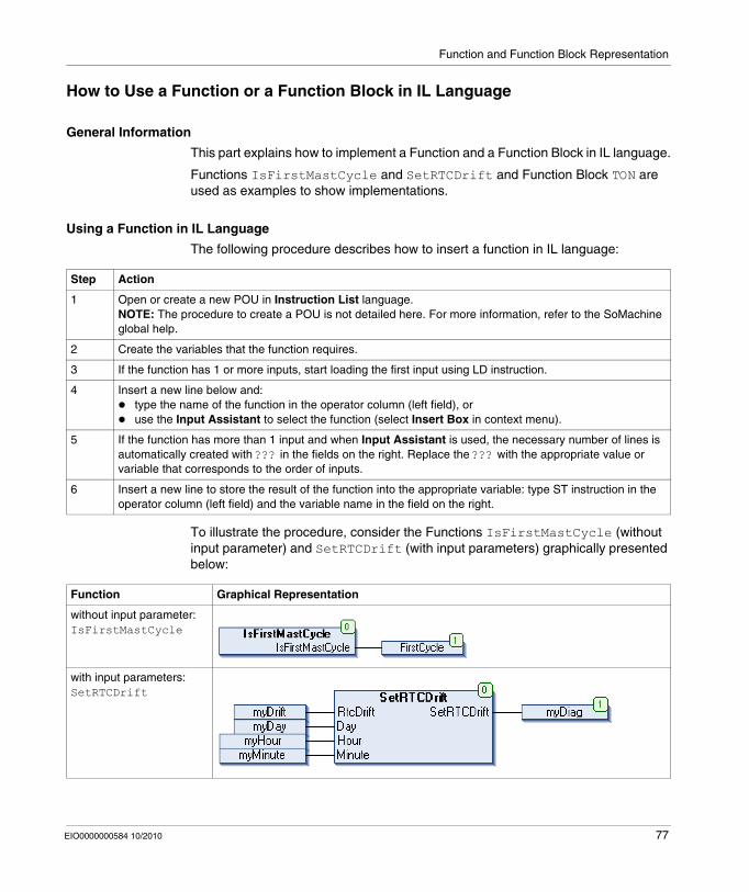
The following procedure describes how to insert a function in IL language:
To illustrate the procedure, consider the Functions IsFirstMastCycle (without input parameter) and SetRTCDrift (with input parameters) graphically presented below:
Step Action
1 Open or create a new POU in Instruction List language.NOTE: The procedure to create a POU is not detailed here. For more information, refer to the SoMachine global help.
2 Create the variables that the function requires.
3 If the function has 1 or more inputs, start loading the first input using LD instruction.
4 Insert a new line below and:type the name of the function in the operator column (left field), oruse the Input Assistant to select the function (select Insert Box in context menu).
5 If the function has more than 1 input and when Input Assistant is used, the necessary number of lines is automatically created with ??? in the fields on the right. Replace the ??? with the appropriate value or variable that corresponds to the order of inputs.
6 Insert a new line to store the result of the function into the appropriate variable: type ST instruction in the operator column (left field) and the variable name in the field on the right.
Function Graphical Representation
without input parameter:IsFirstMastCycle
with input parameters:SetRTCDrift
EIO0000000584 10/2010 77

Function and Function Block Representation
In IL language, the function name is used directly in the Operator Column:
Using a Function Block in IL language
The following procedure describes how to insert a function block in IL language:
Function Representation in SoMachine POU IL Editor
IL example of a function without input parameter:IsFirstMastCycle
IL example of a function with input parameters:SetRTCDrift
Step Action
1 Open or create a new POU in Instruction List language.NOTE: The procedure to create a POU is not detailed here. For more information, refer to the SoMachine global help.
2 Create the variables that the function block requires, including the instance name.
78 EIO0000000584 10/2010
Function and Function Block Representation
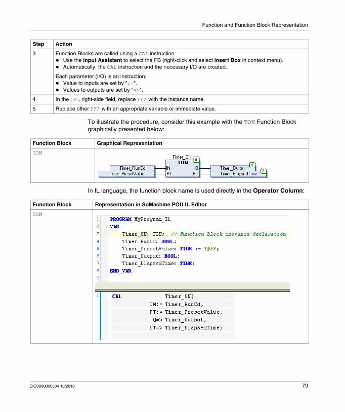
To illustrate the procedure, consider this example with the TON Function Block graphically presented below:
In IL language, the function block name is used directly in the Operator Column:
3 Function Blocks are called using a CAL instruction:Use the Input Assistant to select the FB (right-click and select Insert Box in context menu).Automatically, the CAL instruction and the necessary I/O are created.
Each parameter (I/O) is an instruction:Value to inputs are set by ":=".Values to outputs are set by "=>".
4 In the CAL right-side field, replace ??? with the instance name.
5 Replace other ??? with an appropriate variable or immediate value.
Step Action
Function Block Graphical Representation
TON
Function Block Representation in SoMachine POU IL Editor
TON
EIO0000000584 10/2010 79

Function and Function Block Representation
How to Use a Function or a Function Block in ST Language
General Information
This part explains how to implement a Function and a Function Block in ST language.
Function SetRTCDrift and Function Block TON are used as examples to show implementations.
Using a Function in ST Language
The following procedure describes how to insert a function in ST language:
To illustrate the procedure, consider the function SetRTCDrift graphically presented below:
The ST language of this function is the following:
Step Action
1 Open or create a new POU in Structured Text language.NOTE: The procedure to create a POU is not detailed here. For more information, refer to the SoMachine global help.
2 Create the variables that the function requires.
3 Use the general syntax in the POU ST Editor for the ST language of a function. The general syntax is:FunctionResult:= FunctionName(VarInput1, VarInput2,.. VarInputx);
Function Graphical Representation
SetRTCDrift
Function Representation in SoMachine POU ST Editor
SetRTCDrift PROGRAM MyProgram_STVAR myDrift: SINT(-29..29) := 5;myDay: DAY_OF_WEEK := SUNDAY;myHour: HOUR := 12;myMinute: MINUTE;myRTCAdjust: RTCDRIFT_ERROR;END_VAR
myRTCAdjust:= SetRTCDrift(myDrift, myDay, myHour, myMinute);
80 EIO0000000584 10/2010

Function and Function Block Representation
Using a Function Block in ST Language
The following procedure describes how to insert a function block in ST language:
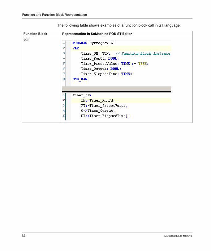
To illustrate the procedure, consider this example with the TON function block graphically presented below:
Step Action
1 Open or create a new POU in Structured Text language.NOTE: The procedure to create a POU is not detailed here. For more information, refer to the SoMachine global help.
2 Create the input and output variables and the instance required for the function block:Input variables are the input parameters required by the function blockOutput variables receive the value returned by the function block
3 Use the general syntax in the POU ST Editor for the ST language of a Function Block. The general syntax is:FunctionBlock_InstanceName(Input1:=VarInput1, Input2:=VarInput2,... Ouput1=>VarOutput1, Ouput2=>VarOutput2,...);
Function Block Graphical Representation
TON
EIO0000000584 10/2010 81
Function and Function Block Representation
The following table shows examples of a function block call in ST language:
Function Block Representation in SoMachine POU ST Editor
TON
82 EIO0000000584 10/2010

Glossary
EIO0000000584 10/2010
Glossary
0-9
1-phase counterA 1-phase counter uses 1 hardware input as counter input. It usually counts up or counts down when there is pulse signal in the input.
2-phase counterA 2-phase counter uses the phase difference between 2 input counter signals to count up or count down.
B
BOOLA Boolean type is the basic data type in computing. A BOOL variable can have one of these values: 0 (FALSE), 1 (TRUE). A bit that is extracted from a word is of type BOOL, for example: %MW10.4 is a fifth bit a memory word number 10.
Boot applicationFiles that contain machine dependent parameters:
machine namedevice name or IP addressModbus Serial Line addressRouting table
EIO0000000584 10/2010 83

Glossary
BOOTPThe Bootstrap Protocol is a UDP network protocol that can be used by a network client to automatically obtain an IP address (and possibly other data) from a server. The client identifies itself to the server using the client’s MAC address. The server—which maintains a pre-configured table of client device MAC addresses and associated IP addresses—sends the client its pre-configured IP address. BOOTP was originally used as a method that enabled diskless hosts to be remotely booted over a network. The BOOTP process assigns an infinite lease of an IP address. The BOOTP service utilizes UDP ports 67 and 68.
BYTEWhen 8 bits are grouped together, they are called a BYTE. You can enter a BYTE either in binary mode or in base 8. The BYTE type is encoded in an 8-bit format that ranges from 16#00 to 16#FF (in hexadecimal format).
C
CANThe Controller Area Network protocol (ISO 11898) for serial bus networks is designed for the interconnection of smart devices (from multiple manufacturers) in smart systems for real-time industrial applications. CAN multi-master systems ensure high data integrity through the implementation of broadcast messaging and advanced diagnostic mechanisms. Originally developed for use in automobiles, CAN is now used in a variety of industrial automation control environments.
CANopenCANopen is an open industry-standard communication protocol and device profile specification.
CFCThe Continuous Function Chart (an extension of the IEC61131-3 standard) is a graphical programming language that works like a flowchart. By adding simple logicals blocks (AND, OR, etc.), each function or function block in the program is represented in this graphical format. For each block, the inputs are on the left and the outputs on the right. Block outputs can be linked to inputs of other blocks in order to create complex expressions.
controllerA controller (or “programmable logic controller,” or “programmable controller”) is used to automate industrial processes.
84 EIO0000000584 10/2010

Glossary
E
expansion busThe expansion bus is an electronic communication bus between expansion modules and a CPU.
expansion I/O moduleAn expansion input or output module is either a digital or analog module that adds additional I/O to the base controller.
F
FBDA Function Block Diagram is a graphically oriented programming language, compliant with IEC 61131-3. It works with a list of networks whereby each network contains a graphical structure of boxes and connection lines which represents either a logical or arithmetic expression, the call of a function block, a jump, or a return instruction.
firmwareThe firmware represents the operating system on a controller.
Function Block(FB) A Program unit of inputs and variables organized to calculate values for outputs based on a defined function such as a timer or a counter.
Function Block Diagram language(FBD) A function block diagram describes a function between input variables and output variables. A function is described as a set of elementary blocks. Input and output variables are connected to blocks by connection lines. An output of a block may also be connected to an input of another block.
G
GVLThe Global Variable List manages global variables that are available in every application POU.
EIO0000000584 10/2010 85

Glossary
H
HMIA human-machine interface is an operator interface (usually graphical) for industrial equipment.
HSChigh-speed counter
I
IEC 61131-3The IEC 61131-3 is an international electrotechnical commission standard for industrial automation equipment (like controllers). IEC 61131-3 deals with controller programming languages and defines 2 graphical and 2 textual programming language standards:
graphical: ladder diagram, function block diagramtextual: structured text, instruction list
ILA program written in the Instruction List language is composed of a series of instructions executed sequentially by the controller. Each instruction includes a line number, an instruction code, and an operand. (IL is IEC 61131-3 compliant.)
L
LDA program in the Ladder Diagram language includes a graphical representation of instructions of a controller program with symbols for contacts, coils, and blocks in a series of rungs executed sequentially by a controller. IEC 61131-3 compliant.
located variableA located variable has an address. (See unlocated variable.)
86 EIO0000000584 10/2010
Glossary
M
ModbusThe Modbus communication protocol allows communications between many devices connected to the same network.
N
NEMAThe National Electrical Manufacturers Association publishes standards for the performance of various classes of electrical enclosures. The NEMA standards cover corrosion resistance, ability to protect from rain and submersion, etc. For IEC member countries, the IEC 60529 standard classifies the ingress protection rating for enclosures.
P
PLCThe Programmable Logic Controller is the “brain” of an industrial manufacturing process. It automates a process, used instead of relay control systems. PLCs are computers suited to survive the harsh conditions of the industrial environment.
PLIPulse Latch Input
POUA Program Organization Unit includes a variable declaration in source code and the corresponding instruction set. POUs facilitate the modular reuse of software programs, functions, and function blocks. Once declared, POUs are available to one another. SoMachine programming requires the utilization of POUs.
PTOPulse Train Outputs are used to control for instance stepper motors in open loop.
EIO0000000584 10/2010 87
Glossary
PWMPulse Width Modulation is used for regulation processes (e.g. actuators for temperature control) where a pulse signal is modulated in its length. For these kind of signals, transistor outputs are used.
R
reflex outputIn a counting mode, the high speed counter’s current value is measured against its configured thresholds to determine the state of these dedicated outputs.
retained dataA retained data value is used in the next power-on or warm start. The value is retained even after an uncontrolled shutdown of the controller or a normal switch-off of the controller.
RTCThe real-time clock option keeps the time for a limited amount of time even when the controller is not powered.
S
SFCA program written in the Sequential Function Chart language can be used for processes that can be split into steps. SFC is composed of steps with associated actions, transitions with associated logic condition, and directed links between steps and transitions. (The SFC standard is defined in IEC 848. It is IEC 61131-3 compliant.)
Structured TextA program written in the structured text (ST) language includes complex statements and nested instructions (such as iteration loops, conditional executions, or functions). ST is compliant with IEC 61131-3.
system variableA system variable structure provides controller data and diagnostic information and allows sending commands to the controller.
88 EIO0000000584 10/2010

Glossary
U
unlocated variableAn unlocated variable does not have an address. (See located variable.)
EIO0000000584 10/2010 89

Glossary
90 EIO0000000584 10/2010

Index
EIO0000000584 10/2010
CBA
IndexDData Types
DAY_OF_WEEK, 70ETH_R_FRAME_PROTOCOL, 57ETH_R_IP_MODE, 56ETH_R_PORT_DUPLEX_STATUS, 58ETH_R_PORT_IP_STATUS, 61ETH_R_PORT_LINK_STATUS, 59ETH_R_PORT_SPEED, 60ETH_R_RUN_IDLE, 62HOUR, 71LED_BHV, 66LED_BHV_ERROR, 67LED_COLOR, 68LED_ID, 65MINUTE, 72PLC_R_APPLICATION_ERROR, 47PLC_R_BOOT_PROJECT_STATUS, 48PLC_R_IO_STATUS, 49PLC_R_STATUS, 50PLC_R_STOP_CAUSE, 51PLC_R_TERMINAL_PORT_STATUS, 52PLC_R_USB_HOST_STATUS, 53PLC_W_COMMAND, 54RTCSETDRIFT_ERROR, 69TM5_MODULE_STATE, 63
DAY_OF_WEEKData Types, 70
DM72FGetImmediateInputFunctions, 33
EIO0000000584 10/2010
EETH_R
System Variable, 25ETH_R_FRAME_PROTOCOL
Data Types, 57ETH_R_IP_MODE
Data Types, 56ETH_R_PORT_DUPLEX_STATUS
Data Types, 58ETH_R_PORT_LINK_STATUS
Data Types, 59ETH_R_PORT_SPEED
Data Types, 60ETH_W
System Variable, 29
FFunctions
Differences Between a Function and a Function Block, 76DM72FGetImmediateInput, 33getTM5Delay, 34How to Use a Function or a Function Block in IL Language, 77How to Use a Function or a Function Block in ST Language, 80IsFirstMastColdCycle, 36IsFirstMastCycle, 37IsFirstMastWarmCycle, 39SetLEDBehaviour, 41SetRTCDrift, 43
91

Index
GgetTM5Delay
Functions, 34
HHOUR
Data Types, 71
IIsFirstMastColdCycle
Functions, 36IsFirstMastCycle
Functions, 37IsFirstMastWarmCycle
Functions, 39
LLED_BHV
Data Types, 66LED_BHV_ERROR
Data Types, 67LED_COLOR
Data Types, 68LED_ID
Data Types, 65
MMINUTE
Data Types, 72
PPLC_R
System Variable, 16PLC_R_APPLICATION_ERROR
Data Types, 47PLC_R_BOOT_PROJECT_STATUS
Data Types, 48PLC_R_IO_STATUS
Data Types, 49
92
PLC_R_STATUSData Types, 50
PLC_R_STOP_CAUSEData Types, 51
PLC_R_TERMINAL_PORT_STATUSData Types, 52
PLC_R_USB_HOST_STATUSData Types, 53
PLC_WSystem Variable, 20
PLC_W_COMMANDData Types, 54
RRTCSETDRIFT_ERROR
Data Types, 69
SSERIAL_R
System Variable, 22SERIAL_W
System Variable, 23SetLEDBehaviour
Functions, 41SetRTCDrift
Functions, 43System Variable
ETH_R, 25ETH_W, 29PLC_R, 16PLC_W, 20SERIAL_R, 22SERIAL_W, 23TM5_MODULE_R, 30
System VariablesDefinition, 11Using, 13
EIO0000000584 10/2010
Index
TTM5_MODULE_R
System Variable, 30TM5_MODULE_STATE
Data Types, 63
EIO0000000584 10/2010
93
Index
94 EIO0000000584 10/2010