Modicon Ladder Logic Block Library User Guide Volume 4 Documents/PLC Modicon... · 043505766 79...
462
Modicon Ladder Logic Block Library User Guide Volume 4 840USE10100 Version 5.0 043505766 79
Transcript of Modicon Ladder Logic Block Library User Guide Volume 4 Documents/PLC Modicon... · 043505766 79...

0435
0576
6 79
ModiconLadder Logic Block LibraryUser GuideVolume 4840USE10100 Version 5.0
0435
0576
6 79

ii 840USE10100 April 2004

Document Set
At a Glance This manual consists of four volumes.
Volume 1� General Information and Instruction Descriptions (A - D)
Volume 2� Instruction Descriptions (E)
Volume 3� Instruction Descriptions (F - N)
Volume 4� General Information and Instruction Descriptions (O - X) and Appendix
840USE10100 April 2004 iii

iv 840USE10100 April 2004

Table of Contents
Safety Information . . . . . . . . . . . . . . . . . . . . . . . . . . . . . . . . . xxxi
About the Book . . . . . . . . . . . . . . . . . . . . . . . . . . . . . . . . . . . xxxiii
Part I General Information . . . . . . . . . . . . . . . . . . . . . . . . . . . . . . 1Introduction . . . . . . . . . . . . . . . . . . . . . . . . . . . . . . . . . . . . . . . . . . . . . . . . . . . . . . 1
Chapter 1 Ladder Logic Overview . . . . . . . . . . . . . . . . . . . . . . . . . . . . . . . .3At a Glance . . . . . . . . . . . . . . . . . . . . . . . . . . . . . . . . . . . . . . . . . . . . . . . . . . . . . . 3Segments and Networks in Ladder Logic . . . . . . . . . . . . . . . . . . . . . . . . . . . . . . . 4How a PLC Solves Ladder Logic. . . . . . . . . . . . . . . . . . . . . . . . . . . . . . . . . . . . . . 7Ladder Logic Elements and Instructions . . . . . . . . . . . . . . . . . . . . . . . . . . . . . . . . 8
Chapter 2 Memory Allocation in a PLC . . . . . . . . . . . . . . . . . . . . . . . . . . . 15At a Glance . . . . . . . . . . . . . . . . . . . . . . . . . . . . . . . . . . . . . . . . . . . . . . . . . . . . . 15User Memory. . . . . . . . . . . . . . . . . . . . . . . . . . . . . . . . . . . . . . . . . . . . . . . . . . . . 16State RAM Values. . . . . . . . . . . . . . . . . . . . . . . . . . . . . . . . . . . . . . . . . . . . . . . . 18State RAM Structure . . . . . . . . . . . . . . . . . . . . . . . . . . . . . . . . . . . . . . . . . . . . . . 20The Configuration Table . . . . . . . . . . . . . . . . . . . . . . . . . . . . . . . . . . . . . . . . . . . 22The I/O Map Table . . . . . . . . . . . . . . . . . . . . . . . . . . . . . . . . . . . . . . . . . . . . . . . 27
Chapter 3 Ladder Logic Opcodes. . . . . . . . . . . . . . . . . . . . . . . . . . . . . . . . 29At a Glance . . . . . . . . . . . . . . . . . . . . . . . . . . . . . . . . . . . . . . . . . . . . . . . . . . . . . 29Translating Ladder Logic Elements in the System Memory Database . . . . . . . . 30Translating DX Instructions in the System Memory Database . . . . . . . . . . . . . . 33Opcode Defaults for Loadables. . . . . . . . . . . . . . . . . . . . . . . . . . . . . . . . . . . . . . 37
Chapter 4 Instructions . . . . . . . . . . . . . . . . . . . . . . . . . . . . . . . . . . . . . . . . . 39Parameter Assignment of Instuctions . . . . . . . . . . . . . . . . . . . . . . . . . . . . . . . . . 39
Chapter 5 Instruction Groups . . . . . . . . . . . . . . . . . . . . . . . . . . . . . . . . . . .41At a Glance . . . . . . . . . . . . . . . . . . . . . . . . . . . . . . . . . . . . . . . . . . . . . . . . . . . . . 41Instruction Groups. . . . . . . . . . . . . . . . . . . . . . . . . . . . . . . . . . . . . . . . . . . . . . . . 42ASCII Functions . . . . . . . . . . . . . . . . . . . . . . . . . . . . . . . . . . . . . . . . . . . . . . . . . 43Counters and Timers Instructions . . . . . . . . . . . . . . . . . . . . . . . . . . . . . . . . . . . . 44Fast I/O Instructions . . . . . . . . . . . . . . . . . . . . . . . . . . . . . . . . . . . . . . . . . . . . . . 45
840USE10100 April 2004 v

Loadable DX . . . . . . . . . . . . . . . . . . . . . . . . . . . . . . . . . . . . . . . . . . . . . . . . . . . . 46Math Instructions . . . . . . . . . . . . . . . . . . . . . . . . . . . . . . . . . . . . . . . . . . . . . . . . . 47Matrix Instructions . . . . . . . . . . . . . . . . . . . . . . . . . . . . . . . . . . . . . . . . . . . . . . . . 49Miscellaneous . . . . . . . . . . . . . . . . . . . . . . . . . . . . . . . . . . . . . . . . . . . . . . . . . . . 50Move Instructions. . . . . . . . . . . . . . . . . . . . . . . . . . . . . . . . . . . . . . . . . . . . . . . . . 51Skips/Specials . . . . . . . . . . . . . . . . . . . . . . . . . . . . . . . . . . . . . . . . . . . . . . . . . . . 52Special Instructions . . . . . . . . . . . . . . . . . . . . . . . . . . . . . . . . . . . . . . . . . . . . . . . 53Coils, Contacts and Interconnects . . . . . . . . . . . . . . . . . . . . . . . . . . . . . . . . . . . . 54
Chapter 6 Equation Networks . . . . . . . . . . . . . . . . . . . . . . . . . . . . . . . . . . 55At a Glance . . . . . . . . . . . . . . . . . . . . . . . . . . . . . . . . . . . . . . . . . . . . . . . . . . . . . 55Equation Network Structure. . . . . . . . . . . . . . . . . . . . . . . . . . . . . . . . . . . . . . . . . 56Mathematical Equations in Equation Networks . . . . . . . . . . . . . . . . . . . . . . . . . . 59Mathematical Operations in Equation Networks . . . . . . . . . . . . . . . . . . . . . . . . . 64Mathematical Functions in Equation Networks . . . . . . . . . . . . . . . . . . . . . . . . . . 69Data Conversions in an Equation Network . . . . . . . . . . . . . . . . . . . . . . . . . . . . . 72Roundoff Differences in PLCs without a Math Coprocessor . . . . . . . . . . . . . . . . 74Benchmark Performance . . . . . . . . . . . . . . . . . . . . . . . . . . . . . . . . . . . . . . . . . . . 75
Chapter 7 Closed Loop Control / Analog Values . . . . . . . . . . . . . . . . . . . 77At a Glance . . . . . . . . . . . . . . . . . . . . . . . . . . . . . . . . . . . . . . . . . . . . . . . . . . . . . 77Closed Loop Control / Analog Values . . . . . . . . . . . . . . . . . . . . . . . . . . . . . . . . . 78PCFL Subfunctions . . . . . . . . . . . . . . . . . . . . . . . . . . . . . . . . . . . . . . . . . . . . . . . 79A PID Example. . . . . . . . . . . . . . . . . . . . . . . . . . . . . . . . . . . . . . . . . . . . . . . . . . . 83PID2 Level Control Example . . . . . . . . . . . . . . . . . . . . . . . . . . . . . . . . . . . . . . . . 87
Chapter 8 Formatting Messages for ASCII READ/WRIT Operations . . . 91At a Glance . . . . . . . . . . . . . . . . . . . . . . . . . . . . . . . . . . . . . . . . . . . . . . . . . . . . . 91Formatting Messages for ASCII READ/WRIT Operations. . . . . . . . . . . . . . . . . . 92Format Specifiers. . . . . . . . . . . . . . . . . . . . . . . . . . . . . . . . . . . . . . . . . . . . . . . . . 93Special Set-up Considerations for Control/Monitor Signals Format. . . . . . . . . . . 96
Chapter 9 Coils, Contacts and Interconnects. . . . . . . . . . . . . . . . . . . . . . 99At a Glance . . . . . . . . . . . . . . . . . . . . . . . . . . . . . . . . . . . . . . . . . . . . . . . . . . . . . 99Coils . . . . . . . . . . . . . . . . . . . . . . . . . . . . . . . . . . . . . . . . . . . . . . . . . . . . . . . . . . 100Contacts. . . . . . . . . . . . . . . . . . . . . . . . . . . . . . . . . . . . . . . . . . . . . . . . . . . . . . . 102Interconnects (Shorts) . . . . . . . . . . . . . . . . . . . . . . . . . . . . . . . . . . . . . . . . . . . . 104
Chapter 10 Interrupt Handling . . . . . . . . . . . . . . . . . . . . . . . . . . . . . . . . . . 105Interrupt Handling . . . . . . . . . . . . . . . . . . . . . . . . . . . . . . . . . . . . . . . . . . . . . . . 105
Chapter 11 Subroutine Handling . . . . . . . . . . . . . . . . . . . . . . . . . . . . . . . . 107Subroutine Handling . . . . . . . . . . . . . . . . . . . . . . . . . . . . . . . . . . . . . . . . . . . . . 107
Chapter 12 Installation of DX Loadables. . . . . . . . . . . . . . . . . . . . . . . . . . 109Installation of DX Loadables . . . . . . . . . . . . . . . . . . . . . . . . . . . . . . . . . . . . . . . 109
vi 840USE10100 April 2004

Part II Instruction Descriptions (A to D) . . . . . . . . . . . . . . . . . 111At a Glance . . . . . . . . . . . . . . . . . . . . . . . . . . . . . . . . . . . . . . . . . . . . . . . . . . . . 111
Chapter 13 1X3X - Input Simulation . . . . . . . . . . . . . . . . . . . . . . . . . . . . . .113At A Glance . . . . . . . . . . . . . . . . . . . . . . . . . . . . . . . . . . . . . . . . . . . . . . . . . . . . 113Short Description: 1X3X - Input Simulation. . . . . . . . . . . . . . . . . . . . . . . . . . . . 114Representation: 1X3X - Input Simulation . . . . . . . . . . . . . . . . . . . . . . . . . . . . . 115
Chapter 14 AD16: Ad 16 Bit. . . . . . . . . . . . . . . . . . . . . . . . . . . . . . . . . . . . .117At a Glance . . . . . . . . . . . . . . . . . . . . . . . . . . . . . . . . . . . . . . . . . . . . . . . . . . . . 117Short Description. . . . . . . . . . . . . . . . . . . . . . . . . . . . . . . . . . . . . . . . . . . . . . . . 118Representation: AD16 - 16-bit Addition. . . . . . . . . . . . . . . . . . . . . . . . . . . . . . . 119
Chapter 15 ADD: Addition . . . . . . . . . . . . . . . . . . . . . . . . . . . . . . . . . . . . . . 121At a Glance . . . . . . . . . . . . . . . . . . . . . . . . . . . . . . . . . . . . . . . . . . . . . . . . . . . . 121Short Description. . . . . . . . . . . . . . . . . . . . . . . . . . . . . . . . . . . . . . . . . . . . . . . . 122Representation: ADD - Single Precision Add . . . . . . . . . . . . . . . . . . . . . . . . . . 123
Chapter 16 AND: Logical And . . . . . . . . . . . . . . . . . . . . . . . . . . . . . . . . . . .125At a Glance . . . . . . . . . . . . . . . . . . . . . . . . . . . . . . . . . . . . . . . . . . . . . . . . . . . . 125Short Description. . . . . . . . . . . . . . . . . . . . . . . . . . . . . . . . . . . . . . . . . . . . . . . . 126Representation: AND - Logical And . . . . . . . . . . . . . . . . . . . . . . . . . . . . . . . . . 127Parameter Description. . . . . . . . . . . . . . . . . . . . . . . . . . . . . . . . . . . . . . . . . . . . 129
Chapter 17 BCD: Binary to Binary Code . . . . . . . . . . . . . . . . . . . . . . . . . . 131At a Glance . . . . . . . . . . . . . . . . . . . . . . . . . . . . . . . . . . . . . . . . . . . . . . . . . . . . 131Short Description. . . . . . . . . . . . . . . . . . . . . . . . . . . . . . . . . . . . . . . . . . . . . . . . 132Representation: BCD - Binary Coded Decimal Conversion . . . . . . . . . . . . . . . 133
Chapter 18 BLKM: Block Move . . . . . . . . . . . . . . . . . . . . . . . . . . . . . . . . . .135At a Glance . . . . . . . . . . . . . . . . . . . . . . . . . . . . . . . . . . . . . . . . . . . . . . . . . . . . 135Short Description. . . . . . . . . . . . . . . . . . . . . . . . . . . . . . . . . . . . . . . . . . . . . . . . 136Representation: BLKM - Block Move . . . . . . . . . . . . . . . . . . . . . . . . . . . . . . . . 137
Chapter 19 BLKT: Block to Table . . . . . . . . . . . . . . . . . . . . . . . . . . . . . . . . 139At a Glance . . . . . . . . . . . . . . . . . . . . . . . . . . . . . . . . . . . . . . . . . . . . . . . . . . . . 139Short Description. . . . . . . . . . . . . . . . . . . . . . . . . . . . . . . . . . . . . . . . . . . . . . . . 140Representation: BLKT - Block-to-Table Move. . . . . . . . . . . . . . . . . . . . . . . . . . 141Parameter Description. . . . . . . . . . . . . . . . . . . . . . . . . . . . . . . . . . . . . . . . . . . . 142
Chapter 20 BMDI: Block Move with Interrupts Disabled . . . . . . . . . . . . . 143At a Glance . . . . . . . . . . . . . . . . . . . . . . . . . . . . . . . . . . . . . . . . . . . . . . . . . . . . 143Short Description: BMDI - Block Move Interrupts Disabled. . . . . . . . . . . . . . . . 144Representation: BMDI - Block Move Interrupts Disabled . . . . . . . . . . . . . . . . . 145
Chapter 21 BROT: Bit Rotate . . . . . . . . . . . . . . . . . . . . . . . . . . . . . . . . . . . 147At a Glance . . . . . . . . . . . . . . . . . . . . . . . . . . . . . . . . . . . . . . . . . . . . . . . . . . . . 147
840USE10100 April 2004 vii

Short Description . . . . . . . . . . . . . . . . . . . . . . . . . . . . . . . . . . . . . . . . . . . . . . . . 148Representation: BROT - Bit Rotate . . . . . . . . . . . . . . . . . . . . . . . . . . . . . . . . . . 149Parameter Description . . . . . . . . . . . . . . . . . . . . . . . . . . . . . . . . . . . . . . . . . . . . 150
Chapter 22 CALL: Activate Immediate or Deferred DX Function . . . . . . 151AT A GLANCE . . . . . . . . . . . . . . . . . . . . . . . . . . . . . . . . . . . . . . . . . . . . . . . . . . 151Short Description: CALL - Activate Immediate or Deferred DX Function. . . . . . 152Representation: CALL - Activate Immediate DX Function. . . . . . . . . . . . . . . . . 153Representation: CALL - Activate Deferred DX Function . . . . . . . . . . . . . . . . . . 156
Chapter 23 CANT - Interpret Coils, Contacts, Timers, Counters, and the SUB Block. . . . . . . . . . . . . . . . . . . . . . . . . . . . . . . . . . . . . . . . . 159At A Glance . . . . . . . . . . . . . . . . . . . . . . . . . . . . . . . . . . . . . . . . . . . . . . . . . . . . 159Short Description: CANT - Interpret Coils, Contacts, Timers, Counters, and the SUB Block. . . . . . . . . . . . . . . . . . . . . . . . . . . . . . . . . . . . . . . . . . . . . . . 160Representation: CANT - Interpret Coils, Contacts, Timers, Counters, and the SUB Block. . . . . . . . . . . . . . . . . . . . . . . . . . . . . . . . . . . . . . . . . . . . . . . 161Parameter Description: CANT - Interpret Coils, Contacts, Timers, Counters, and the SUB Block. . . . . . . . . . . . . . . . . . . . . . . . . . . . . . . . . . . . . . . . . . . . . . . 162
Chapter 24 CHS: Configure Hot Standby . . . . . . . . . . . . . . . . . . . . . . . . . 165At a Glance . . . . . . . . . . . . . . . . . . . . . . . . . . . . . . . . . . . . . . . . . . . . . . . . . . . . 165Short Description . . . . . . . . . . . . . . . . . . . . . . . . . . . . . . . . . . . . . . . . . . . . . . . . 166Representation: CHS - Configure Hot Standby . . . . . . . . . . . . . . . . . . . . . . . . . 167Detailed Description. . . . . . . . . . . . . . . . . . . . . . . . . . . . . . . . . . . . . . . . . . . . . . 169
Chapter 25 CKSM: Check Sum. . . . . . . . . . . . . . . . . . . . . . . . . . . . . . . . . . 173At a Glance . . . . . . . . . . . . . . . . . . . . . . . . . . . . . . . . . . . . . . . . . . . . . . . . . . . . 173Short Description . . . . . . . . . . . . . . . . . . . . . . . . . . . . . . . . . . . . . . . . . . . . . . . . 174Representation: CKSM - Checksum . . . . . . . . . . . . . . . . . . . . . . . . . . . . . . . . . 175Parameter Description . . . . . . . . . . . . . . . . . . . . . . . . . . . . . . . . . . . . . . . . . . . . 177
Chapter 26 CMPR: Compare Register . . . . . . . . . . . . . . . . . . . . . . . . . . . . 179At a Glance . . . . . . . . . . . . . . . . . . . . . . . . . . . . . . . . . . . . . . . . . . . . . . . . . . . . 179Short Description . . . . . . . . . . . . . . . . . . . . . . . . . . . . . . . . . . . . . . . . . . . . . . . . 180Representation: CMPR - Logical Compare . . . . . . . . . . . . . . . . . . . . . . . . . . . . 181Parameter Description . . . . . . . . . . . . . . . . . . . . . . . . . . . . . . . . . . . . . . . . . . . . 182
Chapter 27 Coils . . . . . . . . . . . . . . . . . . . . . . . . . . . . . . . . . . . . . . . . . . . . . 183At A Glance . . . . . . . . . . . . . . . . . . . . . . . . . . . . . . . . . . . . . . . . . . . . . . . . . . . . 183Short Description: Coils . . . . . . . . . . . . . . . . . . . . . . . . . . . . . . . . . . . . . . . . . . . 184General Usage Guidelines: Coils. . . . . . . . . . . . . . . . . . . . . . . . . . . . . . . . . . . . 185
Chapter 28 COMM - ASCII Communications Function . . . . . . . . . . . . . . 187At A Glance . . . . . . . . . . . . . . . . . . . . . . . . . . . . . . . . . . . . . . . . . . . . . . . . . . . . 187Short Description: COMM - ASCII Communications Block . . . . . . . . . . . . . . . . 188Representation: COMM - ASCII Communications Function . . . . . . . . . . . . . . . 189
viii 840USE10100 April 2004

Chapter 29 COMP: Complement a Matrix . . . . . . . . . . . . . . . . . . . . . . . . . 191At a Glance . . . . . . . . . . . . . . . . . . . . . . . . . . . . . . . . . . . . . . . . . . . . . . . . . . . . 191Short Description. . . . . . . . . . . . . . . . . . . . . . . . . . . . . . . . . . . . . . . . . . . . . . . . 192Representation: COMP - Logical Compliment . . . . . . . . . . . . . . . . . . . . . . . . . 193Parameter Description. . . . . . . . . . . . . . . . . . . . . . . . . . . . . . . . . . . . . . . . . . . . 195
Chapter 30 Contacts . . . . . . . . . . . . . . . . . . . . . . . . . . . . . . . . . . . . . . . . . .197At A Glance . . . . . . . . . . . . . . . . . . . . . . . . . . . . . . . . . . . . . . . . . . . . . . . . . . . . 197Short Description: Contacts. . . . . . . . . . . . . . . . . . . . . . . . . . . . . . . . . . . . . . . . 198Representation: Contacts . . . . . . . . . . . . . . . . . . . . . . . . . . . . . . . . . . . . . . . . . 199
Chapter 31 CONV - Convert Data . . . . . . . . . . . . . . . . . . . . . . . . . . . . . . . . 201At A Glance . . . . . . . . . . . . . . . . . . . . . . . . . . . . . . . . . . . . . . . . . . . . . . . . . . . . 201Short Description: CONV - Convert Data . . . . . . . . . . . . . . . . . . . . . . . . . . . . . 202Representation: CONV - Convert Data . . . . . . . . . . . . . . . . . . . . . . . . . . . . . . . 203
Chapter 32 CTIF - Counter, Timer, and Interrupt Function. . . . . . . . . . . . 205At A Glance . . . . . . . . . . . . . . . . . . . . . . . . . . . . . . . . . . . . . . . . . . . . . . . . . . . . 205Short Description: CTIF - Counter, Timer, and Interrupt Function . . . . . . . . . . 206Representation: CTIF - Counter, Timer, Interrupt Function. . . . . . . . . . . . . . . . 207Parameter Description: CTIF - Register Usage Table (Top Node) . . . . . . . . . . 208
Chapter 33 DCTR: Down Counter . . . . . . . . . . . . . . . . . . . . . . . . . . . . . . . . 215At a Glance . . . . . . . . . . . . . . . . . . . . . . . . . . . . . . . . . . . . . . . . . . . . . . . . . . . . 215Short Description. . . . . . . . . . . . . . . . . . . . . . . . . . . . . . . . . . . . . . . . . . . . . . . . 216Representation: DCTR - Down Counter . . . . . . . . . . . . . . . . . . . . . . . . . . . . . . 217
Chapter 34 DIOH: Distributed I/O Health . . . . . . . . . . . . . . . . . . . . . . . . . . 219At a Glance . . . . . . . . . . . . . . . . . . . . . . . . . . . . . . . . . . . . . . . . . . . . . . . . . . . . 219Short Description. . . . . . . . . . . . . . . . . . . . . . . . . . . . . . . . . . . . . . . . . . . . . . . . 220Representation: DIOH - Distributed I/O Health . . . . . . . . . . . . . . . . . . . . . . . . . 221Parameter Description. . . . . . . . . . . . . . . . . . . . . . . . . . . . . . . . . . . . . . . . . . . . 223
Chapter 35 DISA - Disabled Discrete Monitor. . . . . . . . . . . . . . . . . . . . . . 225At A Glance . . . . . . . . . . . . . . . . . . . . . . . . . . . . . . . . . . . . . . . . . . . . . . . . . . . . 225Short Description: DISA - Disabled Discrete Monitor . . . . . . . . . . . . . . . . . . . . 226Representation: DISA - Disabled Discrete Monitor . . . . . . . . . . . . . . . . . . . . . . 227
Chapter 36 DIV: Divide. . . . . . . . . . . . . . . . . . . . . . . . . . . . . . . . . . . . . . . . . 229At a Glance . . . . . . . . . . . . . . . . . . . . . . . . . . . . . . . . . . . . . . . . . . . . . . . . . . . . 229Short Description. . . . . . . . . . . . . . . . . . . . . . . . . . . . . . . . . . . . . . . . . . . . . . . . 230Representation: DIV - Single Precision Division . . . . . . . . . . . . . . . . . . . . . . . . 231Example . . . . . . . . . . . . . . . . . . . . . . . . . . . . . . . . . . . . . . . . . . . . . . . . . . . . . . 233
Chapter 37 DLOG: Data Logging for PCMCIA Read/Write Support. . . . .235At a Glance . . . . . . . . . . . . . . . . . . . . . . . . . . . . . . . . . . . . . . . . . . . . . . . . . . . . 235Short Description. . . . . . . . . . . . . . . . . . . . . . . . . . . . . . . . . . . . . . . . . . . . . . . . 236
840USE10100 April 2004 ix

Representation: DLOG . . . . . . . . . . . . . . . . . . . . . . . . . . . . . . . . . . . . . . . . . . . 237Parameter Description . . . . . . . . . . . . . . . . . . . . . . . . . . . . . . . . . . . . . . . . . . . . 238Run Time Error Handling . . . . . . . . . . . . . . . . . . . . . . . . . . . . . . . . . . . . . . . . . . 240
Chapter 38 DMTH - Double Precision Math. . . . . . . . . . . . . . . . . . . . . . . . 241At a Glance . . . . . . . . . . . . . . . . . . . . . . . . . . . . . . . . . . . . . . . . . . . . . . . . . . . . 241Short Description: DMTH - Double Precision Math - Addition, Subtraction, Multiplication, and Division. . . . . . . . . . . . . . . . . . . . . . . . . . . . . . . . . . . . . . . . . 242Representation: DMTH - Double Precision Math - Addition, Subtraction, Multiplication, and Division. . . . . . . . . . . . . . . . . . . . . . . . . . . . . . . . . . . . . . . . . 243
Chapter 39 DRUM: DRUM Sequencer . . . . . . . . . . . . . . . . . . . . . . . . . . . . 251At a Glance . . . . . . . . . . . . . . . . . . . . . . . . . . . . . . . . . . . . . . . . . . . . . . . . . . . . 251Short Description . . . . . . . . . . . . . . . . . . . . . . . . . . . . . . . . . . . . . . . . . . . . . . . . 252Representation: DRUM . . . . . . . . . . . . . . . . . . . . . . . . . . . . . . . . . . . . . . . . . . . 253Parameter Description . . . . . . . . . . . . . . . . . . . . . . . . . . . . . . . . . . . . . . . . . . . . 254
Chapter 40 DV16: Divide 16 Bit . . . . . . . . . . . . . . . . . . . . . . . . . . . . . . . . . 257At a Glance . . . . . . . . . . . . . . . . . . . . . . . . . . . . . . . . . . . . . . . . . . . . . . . . . . . . 257Short Description . . . . . . . . . . . . . . . . . . . . . . . . . . . . . . . . . . . . . . . . . . . . . . . . 258Representation: DV16 - 16-bit Division . . . . . . . . . . . . . . . . . . . . . . . . . . . . . . . 259Example. . . . . . . . . . . . . . . . . . . . . . . . . . . . . . . . . . . . . . . . . . . . . . . . . . . . . . . 260
Part III Instruction Descriptions (E) . . . . . . . . . . . . . . . . . . . . . . 261At a Glance . . . . . . . . . . . . . . . . . . . . . . . . . . . . . . . . . . . . . . . . . . . . . . . . . . . . 261
Chapter 41 EARS - Event/Alarm Recording System . . . . . . . . . . . . . . . . 263At A Glance . . . . . . . . . . . . . . . . . . . . . . . . . . . . . . . . . . . . . . . . . . . . . . . . . . . . 263Short Description: EARS - Event/Alarm Recording System . . . . . . . . . . . . . . . 264Representation: EARS - Event/Alarm Recording System . . . . . . . . . . . . . . . . . 265Parameter Description: EARS - Event/Alarm Recording System . . . . . . . . . . . 267
Chapter 42 EMTH: Extended Math . . . . . . . . . . . . . . . . . . . . . . . . . . . . . . . 271At a Glance . . . . . . . . . . . . . . . . . . . . . . . . . . . . . . . . . . . . . . . . . . . . . . . . . . . . 271Short Description . . . . . . . . . . . . . . . . . . . . . . . . . . . . . . . . . . . . . . . . . . . . . . . . 272Representation: EMTH - Extended Math Functions . . . . . . . . . . . . . . . . . . . . . 273Parameter Description . . . . . . . . . . . . . . . . . . . . . . . . . . . . . . . . . . . . . . . . . . . . 274Floating Point EMTH Functions . . . . . . . . . . . . . . . . . . . . . . . . . . . . . . . . . . . . . 276
Chapter 43 EMTH-ADDDP: Double Precision Addition . . . . . . . . . . . . . . 277At a Glance . . . . . . . . . . . . . . . . . . . . . . . . . . . . . . . . . . . . . . . . . . . . . . . . . . . . 277Short Description . . . . . . . . . . . . . . . . . . . . . . . . . . . . . . . . . . . . . . . . . . . . . . . . 278Representation: EMTH - ADDDP - Double Precision Math - Addition . . . . . . . . 279Parameter Description . . . . . . . . . . . . . . . . . . . . . . . . . . . . . . . . . . . . . . . . . . . . 281
Chapter 44 EMTH-ADDFP: Floating Point Addition . . . . . . . . . . . . . . . . . 283At a Glance . . . . . . . . . . . . . . . . . . . . . . . . . . . . . . . . . . . . . . . . . . . . . . . . . . . . 283
x 840USE10100 April 2004
Short Description. . . . . . . . . . . . . . . . . . . . . . . . . . . . . . . . . . . . . . . . . . . . . . . . 284Representation: EMTH - ADDFP - Floating Point Math - Addition . . . . . . . . . . 285Parameter Description. . . . . . . . . . . . . . . . . . . . . . . . . . . . . . . . . . . . . . . . . . . . 286
Chapter 45 EMTH-ADDIF: Integer + Floating Point Addition . . . . . . . . . .287At a Glance . . . . . . . . . . . . . . . . . . . . . . . . . . . . . . . . . . . . . . . . . . . . . . . . . . . . 287Short Description. . . . . . . . . . . . . . . . . . . . . . . . . . . . . . . . . . . . . . . . . . . . . . . . 288Representation: EMTH - ADDIF - Integer + Floating Point Addition . . . . . . . . . 289Parameter Description. . . . . . . . . . . . . . . . . . . . . . . . . . . . . . . . . . . . . . . . . . . . 290
Chapter 46 EMTH-ANLOG: Base 10 Antilogarithm . . . . . . . . . . . . . . . . . . 291At a Glance . . . . . . . . . . . . . . . . . . . . . . . . . . . . . . . . . . . . . . . . . . . . . . . . . . . . 291Short Description. . . . . . . . . . . . . . . . . . . . . . . . . . . . . . . . . . . . . . . . . . . . . . . . 292Representation: EMTH - ANLOG - integer Base 10 Antilogarithm . . . . . . . . . . 293Parameter Description. . . . . . . . . . . . . . . . . . . . . . . . . . . . . . . . . . . . . . . . . . . . 295
Chapter 47 EMTH-ARCOS: Floating Point Arc Cosine of an Angle (in Radians) . . . . . . . . . . . . . . . . . . . . . . . . . . . . . . . . . . . . . . . . 297At a Glance . . . . . . . . . . . . . . . . . . . . . . . . . . . . . . . . . . . . . . . . . . . . . . . . . . . . 297Short Description. . . . . . . . . . . . . . . . . . . . . . . . . . . . . . . . . . . . . . . . . . . . . . . . 298Representation: EMTH - ARCOS - Floating Point Math - Arc Cosine of an Angle (in Radians) . . . . . . . . . . . . . . . . . . . . . . . . . . . . . . . . . . . . . . . . . . . . . . . . . . . . 299Parameter Description. . . . . . . . . . . . . . . . . . . . . . . . . . . . . . . . . . . . . . . . . . . . 301
Chapter 48 EMTH-ARSIN: Floating Point Arcsine of an Angle (in Radians) . . . . . . . . . . . . . . . . . . . . . . . . . . . . . . . . . . . . . . . . 303At a Glance . . . . . . . . . . . . . . . . . . . . . . . . . . . . . . . . . . . . . . . . . . . . . . . . . . . . 303Short Description. . . . . . . . . . . . . . . . . . . . . . . . . . . . . . . . . . . . . . . . . . . . . . . . 304Representation: EMTH - ARSIN - Arcsine of an Angle (in Radians). . . . . . . . . 305Parameter Description. . . . . . . . . . . . . . . . . . . . . . . . . . . . . . . . . . . . . . . . . . . . 306
Chapter 49 EMTH-ARTAN: Floating Point Arc Tangent of an Angle (in Radians) . . . . . . . . . . . . . . . . . . . . . . . . . . . . . . . . . . . . . . . . 307At a Glance . . . . . . . . . . . . . . . . . . . . . . . . . . . . . . . . . . . . . . . . . . . . . . . . . . . . 307Short Description. . . . . . . . . . . . . . . . . . . . . . . . . . . . . . . . . . . . . . . . . . . . . . . . 308Representation: Floating Point Math - Arc Tangent of an Angle (in Radians). . 309Parameter Description. . . . . . . . . . . . . . . . . . . . . . . . . . . . . . . . . . . . . . . . . . . . 311
Chapter 50 EMTH-CHSIN: Changing the Sign of a Floating Point Number . . . . . . . . . . . . . . . . . . . . . . . . . . . . . . . . . . . . . . . . . . . 313At a Glance . . . . . . . . . . . . . . . . . . . . . . . . . . . . . . . . . . . . . . . . . . . . . . . . . . . . 313Short Description. . . . . . . . . . . . . . . . . . . . . . . . . . . . . . . . . . . . . . . . . . . . . . . . 314Representation: EMTH - CHSIN - Change the Sign of a Floating Point Number315Parameter Description. . . . . . . . . . . . . . . . . . . . . . . . . . . . . . . . . . . . . . . . . . . . 317
840USE10100 April 2004 xi

Chapter 51 EMTH-CMPFP: Floating Point Comparison. . . . . . . . . . . . . . 319At a Glance . . . . . . . . . . . . . . . . . . . . . . . . . . . . . . . . . . . . . . . . . . . . . . . . . . . . 319Short Description . . . . . . . . . . . . . . . . . . . . . . . . . . . . . . . . . . . . . . . . . . . . . . . . 320Representation: EMTH - CMFPF - Floating Point Math Comparison . . . . . . . . 321Parameter Description . . . . . . . . . . . . . . . . . . . . . . . . . . . . . . . . . . . . . . . . . . . . 323
Chapter 52 EMTH-CMPIF: Integer-Floating Point Comparison . . . . . . . . 325At a Glance . . . . . . . . . . . . . . . . . . . . . . . . . . . . . . . . . . . . . . . . . . . . . . . . . . . . 325Short Description . . . . . . . . . . . . . . . . . . . . . . . . . . . . . . . . . . . . . . . . . . . . . . . . 326Representation: EMTH - CMPIF - Floating Point Math - Integer/Floating Point Comparison . . . . . . . . . . . . . . . . . . . . . . . . . . . . . . . . . . 327Parameter Description . . . . . . . . . . . . . . . . . . . . . . . . . . . . . . . . . . . . . . . . . . . . 329
Chapter 53 EMTH-CNVDR: Floating Point Conversion of Degrees to Radians . . . . . . . . . . . . . . . . . . . . . . . . . . . . . . . . . . . . . . . . . . . 331At a Glance . . . . . . . . . . . . . . . . . . . . . . . . . . . . . . . . . . . . . . . . . . . . . . . . . . . . 331Short Description . . . . . . . . . . . . . . . . . . . . . . . . . . . . . . . . . . . . . . . . . . . . . . . . 332Representation: EMTH - CNVDR - Conversion of Degrees to Radians . . . . . . 333Parameter Description . . . . . . . . . . . . . . . . . . . . . . . . . . . . . . . . . . . . . . . . . . . . 335
Chapter 54 EMTH-CNVFI: Floating Point to Integer Conversion . . . . . . 337At a Glance . . . . . . . . . . . . . . . . . . . . . . . . . . . . . . . . . . . . . . . . . . . . . . . . . . . . 337Short Description . . . . . . . . . . . . . . . . . . . . . . . . . . . . . . . . . . . . . . . . . . . . . . . . 338Representation: EMTH - CNVFI - Floating Point to Integer Conversion . . . . . . 339Parameter Description . . . . . . . . . . . . . . . . . . . . . . . . . . . . . . . . . . . . . . . . . . . . 341Runtime Error Handling . . . . . . . . . . . . . . . . . . . . . . . . . . . . . . . . . . . . . . . . . . . 342
Chapter 55 EMTH-CNVIF: Integer-to-Floating Point Conversion . . . . . . 343At a Glance . . . . . . . . . . . . . . . . . . . . . . . . . . . . . . . . . . . . . . . . . . . . . . . . . . . . 343Short Description . . . . . . . . . . . . . . . . . . . . . . . . . . . . . . . . . . . . . . . . . . . . . . . . 344Representation: EMTH - CNVIF - Integer to Floating Point Conversion . . . . . . 345Parameter Description . . . . . . . . . . . . . . . . . . . . . . . . . . . . . . . . . . . . . . . . . . . . 347Runtime Error Handling . . . . . . . . . . . . . . . . . . . . . . . . . . . . . . . . . . . . . . . . . . . 348
Chapter 56 EMTH-CNVRD: Floating Point Conversion of Radians to Degrees. . . . . . . . . . . . . . . . . . . . . . . . . . . . . . . . . . . . . . . . . . . 349At a Glance . . . . . . . . . . . . . . . . . . . . . . . . . . . . . . . . . . . . . . . . . . . . . . . . . . . . 349Short Description . . . . . . . . . . . . . . . . . . . . . . . . . . . . . . . . . . . . . . . . . . . . . . . . 350Representation: EMTH - CNVRD - Conversion of Radians to Degrees . . . . . . 351Parameter Description . . . . . . . . . . . . . . . . . . . . . . . . . . . . . . . . . . . . . . . . . . . . 353
Chapter 57 EMTH-COS: Floating Point Cosine of an Angle (in Radians)355At a Glance . . . . . . . . . . . . . . . . . . . . . . . . . . . . . . . . . . . . . . . . . . . . . . . . . . . . 355Short Description . . . . . . . . . . . . . . . . . . . . . . . . . . . . . . . . . . . . . . . . . . . . . . . . 356Representation: EMTH - COS - Cosine of an Angle (in Radians) . . . . . . . . . . . 357Parameter Description . . . . . . . . . . . . . . . . . . . . . . . . . . . . . . . . . . . . . . . . . . . . 358
xii 840USE10100 April 2004

Chapter 58 EMTH-DIVDP: Double Precision Division. . . . . . . . . . . . . . . .359At a Glance . . . . . . . . . . . . . . . . . . . . . . . . . . . . . . . . . . . . . . . . . . . . . . . . . . . . 359Short Description. . . . . . . . . . . . . . . . . . . . . . . . . . . . . . . . . . . . . . . . . . . . . . . . 360Representation: EMTH - DIVDP - Double Precision Math - Division . . . . . . . . 361Parameter Description. . . . . . . . . . . . . . . . . . . . . . . . . . . . . . . . . . . . . . . . . . . . 363Runtime Error Handling. . . . . . . . . . . . . . . . . . . . . . . . . . . . . . . . . . . . . . . . . . . 364
Chapter 59 EMTH-DIVFI: Floating Point Divided by Integer. . . . . . . . . . . 365At a Glance . . . . . . . . . . . . . . . . . . . . . . . . . . . . . . . . . . . . . . . . . . . . . . . . . . . . 365Short Description. . . . . . . . . . . . . . . . . . . . . . . . . . . . . . . . . . . . . . . . . . . . . . . . 366Representation: EMTH - DIVFI - Floating Point Divided by Integer . . . . . . . . . 367Parameter Description. . . . . . . . . . . . . . . . . . . . . . . . . . . . . . . . . . . . . . . . . . . . 368
Chapter 60 EMTH-DIVFP: Floating Point Division. . . . . . . . . . . . . . . . . . . 369At a Glance . . . . . . . . . . . . . . . . . . . . . . . . . . . . . . . . . . . . . . . . . . . . . . . . . . . . 369Short Description. . . . . . . . . . . . . . . . . . . . . . . . . . . . . . . . . . . . . . . . . . . . . . . . 370Representation: EMTH - DIVFP - Floating Point Division . . . . . . . . . . . . . . . . . 371Parameter Description. . . . . . . . . . . . . . . . . . . . . . . . . . . . . . . . . . . . . . . . . . . . 372
Chapter 61 EMTH-DIVIF: Integer Divided by Floating Point. . . . . . . . . . . 373At a Glance . . . . . . . . . . . . . . . . . . . . . . . . . . . . . . . . . . . . . . . . . . . . . . . . . . . . 373Short Description. . . . . . . . . . . . . . . . . . . . . . . . . . . . . . . . . . . . . . . . . . . . . . . . 374Representation: EMTH - DIVIF - Integer Divided by Floating Point . . . . . . . . . 375Parameter Description. . . . . . . . . . . . . . . . . . . . . . . . . . . . . . . . . . . . . . . . . . . . 376
Chapter 62 EMTH-ERLOG: Floating Point Error Report Log . . . . . . . . . . 377At a Glance . . . . . . . . . . . . . . . . . . . . . . . . . . . . . . . . . . . . . . . . . . . . . . . . . . . . 377Short Description. . . . . . . . . . . . . . . . . . . . . . . . . . . . . . . . . . . . . . . . . . . . . . . . 378Representation: EMTH - ERLOG - Floating Point Math - Error Report Log . . . 379Parameter Description. . . . . . . . . . . . . . . . . . . . . . . . . . . . . . . . . . . . . . . . . . . . 381
Chapter 63 EMTH-EXP: Floating Point Exponential Function . . . . . . . . . 383At a Glance . . . . . . . . . . . . . . . . . . . . . . . . . . . . . . . . . . . . . . . . . . . . . . . . . . . . 383Short Description. . . . . . . . . . . . . . . . . . . . . . . . . . . . . . . . . . . . . . . . . . . . . . . . 384Representation: EMTH - EXP - Floating Point Math - Exponential Function . . 385Parameter Description. . . . . . . . . . . . . . . . . . . . . . . . . . . . . . . . . . . . . . . . . . . . 387
Chapter 64 EMTH-LNFP: Floating Point Natural Logarithm. . . . . . . . . . . 389At a Glance . . . . . . . . . . . . . . . . . . . . . . . . . . . . . . . . . . . . . . . . . . . . . . . . . . . . 389Short Description. . . . . . . . . . . . . . . . . . . . . . . . . . . . . . . . . . . . . . . . . . . . . . . . 390Representation: EMTH - LNFP - Natural Logarithm . . . . . . . . . . . . . . . . . . . . . 391Parameter Description. . . . . . . . . . . . . . . . . . . . . . . . . . . . . . . . . . . . . . . . . . . . 393
Chapter 65 EMTH-LOG: Base 10 Logarithm . . . . . . . . . . . . . . . . . . . . . . . 395At a Glance . . . . . . . . . . . . . . . . . . . . . . . . . . . . . . . . . . . . . . . . . . . . . . . . . . . . 395Short Description. . . . . . . . . . . . . . . . . . . . . . . . . . . . . . . . . . . . . . . . . . . . . . . . 396Representation: EMTH - LOG - Integer Math - Base 10 Logarithm . . . . . . . . . 397
840USE10100 April 2004 xiii

Parameter Description . . . . . . . . . . . . . . . . . . . . . . . . . . . . . . . . . . . . . . . . . . . . 399
Chapter 66 EMTH-LOGFP: Floating Point Common Logarithm . . . . . . . 401At a Glance . . . . . . . . . . . . . . . . . . . . . . . . . . . . . . . . . . . . . . . . . . . . . . . . . . . . 401Short Description . . . . . . . . . . . . . . . . . . . . . . . . . . . . . . . . . . . . . . . . . . . . . . . . 402Representation: EMTH - LOGFP - Common Logarithm . . . . . . . . . . . . . . . . . . 403Parameter Description . . . . . . . . . . . . . . . . . . . . . . . . . . . . . . . . . . . . . . . . . . . . 405
Chapter 67 EMTH-MULDP: Double Precision Multiplication . . . . . . . . . . 407At a Glance . . . . . . . . . . . . . . . . . . . . . . . . . . . . . . . . . . . . . . . . . . . . . . . . . . . . 407Short Description . . . . . . . . . . . . . . . . . . . . . . . . . . . . . . . . . . . . . . . . . . . . . . . . 408Representation: EMTH - MULDP - Double Precision Math - Multiplication . . . . 409Parameter Description . . . . . . . . . . . . . . . . . . . . . . . . . . . . . . . . . . . . . . . . . . . . 411
Chapter 68 EMTH-MULFP: Floating Point Multiplication. . . . . . . . . . . . . 413At a Glance . . . . . . . . . . . . . . . . . . . . . . . . . . . . . . . . . . . . . . . . . . . . . . . . . . . . 413Short Description . . . . . . . . . . . . . . . . . . . . . . . . . . . . . . . . . . . . . . . . . . . . . . . . 414Representation: EMTH - MULFP - Floating Point - Multiplication . . . . . . . . . . . 415Parameter Description . . . . . . . . . . . . . . . . . . . . . . . . . . . . . . . . . . . . . . . . . . . . 416
Chapter 69 EMTH-MULIF: Integer x Floating Point Multiplication . . . . . 417At a Glance . . . . . . . . . . . . . . . . . . . . . . . . . . . . . . . . . . . . . . . . . . . . . . . . . . . . 417Short Description . . . . . . . . . . . . . . . . . . . . . . . . . . . . . . . . . . . . . . . . . . . . . . . . 418Representation: EMTH - MULIF - Integer Multiplied by Floating Point . . . . . . . 419Parameter Description . . . . . . . . . . . . . . . . . . . . . . . . . . . . . . . . . . . . . . . . . . . . 421
Chapter 70 EMTH-PI: Load the Floating Point Value of "Pi" . . . . . . . . . . 423At a Glance . . . . . . . . . . . . . . . . . . . . . . . . . . . . . . . . . . . . . . . . . . . . . . . . . . . . 423Short Description . . . . . . . . . . . . . . . . . . . . . . . . . . . . . . . . . . . . . . . . . . . . . . . . 424Representation: EMTH - PI - Floating Point Math - Load the Floating Point Value of PI . . . . . . . . . . . . . . . . . . . . . . . . . . . . . . . . . . 425Parameter Description . . . . . . . . . . . . . . . . . . . . . . . . . . . . . . . . . . . . . . . . . . . . 426
Chapter 71 EMTH-POW: Raising a Floating Point Number to an Integer Power . . . . . . . . . . . . . . . . . . . . . . . . . . . . . . . . . . . . . . . . . . . . 427At a Glance . . . . . . . . . . . . . . . . . . . . . . . . . . . . . . . . . . . . . . . . . . . . . . . . . . . . 427Short Description . . . . . . . . . . . . . . . . . . . . . . . . . . . . . . . . . . . . . . . . . . . . . . . . 428Representation: EMTH - POW - Raising a Floating Point Number to an Integer Power. . . . . . . . . . . . . . . . . . . . . . . . . . . . . . . . . . . . . . . . . . . . . . . . . . . . . . . . . 429Parameter Description . . . . . . . . . . . . . . . . . . . . . . . . . . . . . . . . . . . . . . . . . . . . 430
Chapter 72 EMTH-SINE: Floating Point Sine of an Angle (in Radians) . 431At a Glance . . . . . . . . . . . . . . . . . . . . . . . . . . . . . . . . . . . . . . . . . . . . . . . . . . . . 431Short Description . . . . . . . . . . . . . . . . . . . . . . . . . . . . . . . . . . . . . . . . . . . . . . . . 432Representation: EMTH - SINE - Floating Point Math - Sine of an Angle (in Radians) . . . . . . . . . . . . . . . . . . . . . . . . . . . . . . . . . . . . . . 433Parameter Description . . . . . . . . . . . . . . . . . . . . . . . . . . . . . . . . . . . . . . . . . . . . 435
xiv 840USE10100 April 2004

Chapter 73 EMTH-SQRFP: Floating Point Square Root . . . . . . . . . . . . . .437At a Glance . . . . . . . . . . . . . . . . . . . . . . . . . . . . . . . . . . . . . . . . . . . . . . . . . . . . 437Short Description. . . . . . . . . . . . . . . . . . . . . . . . . . . . . . . . . . . . . . . . . . . . . . . . 438Representation: EMTH - SQRFP - Square Root. . . . . . . . . . . . . . . . . . . . . . . . 439Parameter Description. . . . . . . . . . . . . . . . . . . . . . . . . . . . . . . . . . . . . . . . . . . . 440
Chapter 74 EMTH-SQRT: Floating Point Square Root . . . . . . . . . . . . . . . 441At a Glance . . . . . . . . . . . . . . . . . . . . . . . . . . . . . . . . . . . . . . . . . . . . . . . . . . . . 441Short Description. . . . . . . . . . . . . . . . . . . . . . . . . . . . . . . . . . . . . . . . . . . . . . . . 442Representation: EMTH - SQRT - Square Root . . . . . . . . . . . . . . . . . . . . . . . . . 443Parameter Description. . . . . . . . . . . . . . . . . . . . . . . . . . . . . . . . . . . . . . . . . . . . 445
Chapter 75 EMTH-SQRTP: Process Square Root . . . . . . . . . . . . . . . . . . . 447At a Glance . . . . . . . . . . . . . . . . . . . . . . . . . . . . . . . . . . . . . . . . . . . . . . . . . . . . 447Short Description. . . . . . . . . . . . . . . . . . . . . . . . . . . . . . . . . . . . . . . . . . . . . . . . 448Representation: EMTH - SQRTP - Double Precision Math - Process Square Root . . . . . . . . . . . . . . . . . . . . . . . . . . . . . . . . . . . . . . . . . . . . 449Parameter Description. . . . . . . . . . . . . . . . . . . . . . . . . . . . . . . . . . . . . . . . . . . . 451Example . . . . . . . . . . . . . . . . . . . . . . . . . . . . . . . . . . . . . . . . . . . . . . . . . . . . . . 452
Chapter 76 EMTH-SUBDP: Double Precision Subtraction . . . . . . . . . . . . 453At a Glance . . . . . . . . . . . . . . . . . . . . . . . . . . . . . . . . . . . . . . . . . . . . . . . . . . . . 453Short Description. . . . . . . . . . . . . . . . . . . . . . . . . . . . . . . . . . . . . . . . . . . . . . . . 454Representation: EMTH - SUBDP - Double Precision Math - Subtraction . . . . . 455Parameter Description. . . . . . . . . . . . . . . . . . . . . . . . . . . . . . . . . . . . . . . . . . . . 457
Chapter 77 EMTH-SUBFI: Floating Point - Integer Subtraction . . . . . . . . 459At a Glance . . . . . . . . . . . . . . . . . . . . . . . . . . . . . . . . . . . . . . . . . . . . . . . . . . . . 459Short Description. . . . . . . . . . . . . . . . . . . . . . . . . . . . . . . . . . . . . . . . . . . . . . . . 460Representation: EMTH - SUBFI - Floating Point minus Integer . . . . . . . . . . . . 461Parameter Description. . . . . . . . . . . . . . . . . . . . . . . . . . . . . . . . . . . . . . . . . . . . 462
Chapter 78 EMTH-SUBFP: Floating Point Subtraction . . . . . . . . . . . . . . .463At a Glance . . . . . . . . . . . . . . . . . . . . . . . . . . . . . . . . . . . . . . . . . . . . . . . . . . . . 463Short Description. . . . . . . . . . . . . . . . . . . . . . . . . . . . . . . . . . . . . . . . . . . . . . . . 464Representation: EMTH - SUBFP - Floating Point - Subtraction . . . . . . . . . . . . 465Parameter Description. . . . . . . . . . . . . . . . . . . . . . . . . . . . . . . . . . . . . . . . . . . . 466
Chapter 79 EMTH-SUBIF: Integer - Floating Point Subtraction . . . . . . . . 467At a Glance . . . . . . . . . . . . . . . . . . . . . . . . . . . . . . . . . . . . . . . . . . . . . . . . . . . . 467Short Description. . . . . . . . . . . . . . . . . . . . . . . . . . . . . . . . . . . . . . . . . . . . . . . . 468Representation: EMTH - SUBIF - Integer minus Floating Point . . . . . . . . . . . . 469Parameter Description. . . . . . . . . . . . . . . . . . . . . . . . . . . . . . . . . . . . . . . . . . . . 470
Chapter 80 EMTH-TAN: Floating Point Tangent of an Angle (in Radians) . . . . . . . . . . . . . . . . . . . . . . . . . . . . . . . . . . . . . . . . 471At a Glance . . . . . . . . . . . . . . . . . . . . . . . . . . . . . . . . . . . . . . . . . . . . . . . . . . . . 471
840USE10100 April 2004 xv

Short Description . . . . . . . . . . . . . . . . . . . . . . . . . . . . . . . . . . . . . . . . . . . . . . . . 472Representation: EMTH - TAN - Tangent of an Angle (in Radians) . . . . . . . . . . 473Parameter Description . . . . . . . . . . . . . . . . . . . . . . . . . . . . . . . . . . . . . . . . . . . . 474
Chapter 81 ESI: Support of the ESI Module . . . . . . . . . . . . . . . . . . . . . . . 475At a Glance . . . . . . . . . . . . . . . . . . . . . . . . . . . . . . . . . . . . . . . . . . . . . . . . . . . . 475Short Description . . . . . . . . . . . . . . . . . . . . . . . . . . . . . . . . . . . . . . . . . . . . . . . . 476Representation. . . . . . . . . . . . . . . . . . . . . . . . . . . . . . . . . . . . . . . . . . . . . . . . . . 477Parameter Description . . . . . . . . . . . . . . . . . . . . . . . . . . . . . . . . . . . . . . . . . . . . 478READ ASCII Message (Subfunction 1) . . . . . . . . . . . . . . . . . . . . . . . . . . . . . . . 481WRITE ASCII Message (Subfunction 2) . . . . . . . . . . . . . . . . . . . . . . . . . . . . . . 485GET DATA (Subfunction 3) . . . . . . . . . . . . . . . . . . . . . . . . . . . . . . . . . . . . . . . . 486PUT DATA (Subfunction 4) . . . . . . . . . . . . . . . . . . . . . . . . . . . . . . . . . . . . . . . . 488ABORT (Middle Input ON) . . . . . . . . . . . . . . . . . . . . . . . . . . . . . . . . . . . . . . . . . 492Run Time Errors. . . . . . . . . . . . . . . . . . . . . . . . . . . . . . . . . . . . . . . . . . . . . . . . . 493
Chapter 82 EUCA: Engineering Unit Conversion and Alarms . . . . . . . . 495At a Glance . . . . . . . . . . . . . . . . . . . . . . . . . . . . . . . . . . . . . . . . . . . . . . . . . . . . 495Short Description . . . . . . . . . . . . . . . . . . . . . . . . . . . . . . . . . . . . . . . . . . . . . . . . 496Representation: EUCA - Engineering Unit and Alarm . . . . . . . . . . . . . . . . . . . . 497Parameter Description . . . . . . . . . . . . . . . . . . . . . . . . . . . . . . . . . . . . . . . . . . . . 498Examples . . . . . . . . . . . . . . . . . . . . . . . . . . . . . . . . . . . . . . . . . . . . . . . . . . . . . . 500
Part IV Instruction Descriptions (F to N) . . . . . . . . . . . . . . . . . . 507At a Glance . . . . . . . . . . . . . . . . . . . . . . . . . . . . . . . . . . . . . . . . . . . . . . . . . . . . 507
Chapter 83 FIN: First In . . . . . . . . . . . . . . . . . . . . . . . . . . . . . . . . . . . . . . . . 509At a Glance . . . . . . . . . . . . . . . . . . . . . . . . . . . . . . . . . . . . . . . . . . . . . . . . . . . . 509Short Description . . . . . . . . . . . . . . . . . . . . . . . . . . . . . . . . . . . . . . . . . . . . . . . . 510Representation: FIN - First in. . . . . . . . . . . . . . . . . . . . . . . . . . . . . . . . . . . . . . . 511Parameter Description . . . . . . . . . . . . . . . . . . . . . . . . . . . . . . . . . . . . . . . . . . . . 512
Chapter 84 FOUT: First Out . . . . . . . . . . . . . . . . . . . . . . . . . . . . . . . . . . . . 513At a Glance . . . . . . . . . . . . . . . . . . . . . . . . . . . . . . . . . . . . . . . . . . . . . . . . . . . . 513Short Description . . . . . . . . . . . . . . . . . . . . . . . . . . . . . . . . . . . . . . . . . . . . . . . . 514Representation: FOUT - First Out . . . . . . . . . . . . . . . . . . . . . . . . . . . . . . . . . . . 515Parameter Description . . . . . . . . . . . . . . . . . . . . . . . . . . . . . . . . . . . . . . . . . . . . 517
Chapter 85 FTOI: Floating Point to Integer . . . . . . . . . . . . . . . . . . . . . . . . 519At a Glance . . . . . . . . . . . . . . . . . . . . . . . . . . . . . . . . . . . . . . . . . . . . . . . . . . . . 519Short Description . . . . . . . . . . . . . . . . . . . . . . . . . . . . . . . . . . . . . . . . . . . . . . . . 520Representation: FTOI - Floating Point to Integer Conversion . . . . . . . . . . . . . . 521
Chapter 86 GD92 - Gas Flow Function Block . . . . . . . . . . . . . . . . . . . . . . 523At A Glance . . . . . . . . . . . . . . . . . . . . . . . . . . . . . . . . . . . . . . . . . . . . . . . . . . . . 523Short Description: GD92 - Gas Flow Function Block . . . . . . . . . . . . . . . . . . . . 524Representation: GD92 - Gas Flow Function Block . . . . . . . . . . . . . . . . . . . . . . 525
xvi 840USE10100 April 2004

Parameter Description - Inputs: GD92 - Gas Flow Function Block . . . . . . . . . . 527Parameter Description - Outputs: GD92 - Gas Flow Function Block . . . . . . . . 533Parameter Description - Optional Outputs: GD92 - Gas Flow Function Block . 534
Chapter 87 GFNX AGA#3 ‘85 and NX19 ‘68 Gas Flow Function Block . .535At A Glance . . . . . . . . . . . . . . . . . . . . . . . . . . . . . . . . . . . . . . . . . . . . . . . . . . . . 535Short Description: GFNX - Gas Flow Function Block . . . . . . . . . . . . . . . . . . . . 536Representation: GFNX - Gas Flow Function Block . . . . . . . . . . . . . . . . . . . . . . 537Parameter Description - Inputs: GFNX - Gas Flow Function Block. . . . . . . . . . 539Parameter Description - Outputs: GFNX - Gas Flow Function Block . . . . . . . . 546Parameter Description - Optional Outputs: GFNX - Gas Flow Function Block . 547
Chapter 88 GG92 AGA #3 1992 Gross Method Gas Flow Function Block . . . . . . . . . . . . . . . . . . . . . . . . . . . . . . . . . . . . . . . . . . . . . . . . . .549At A Glance . . . . . . . . . . . . . . . . . . . . . . . . . . . . . . . . . . . . . . . . . . . . . . . . . . . . 549Short Description: GG92 - Gas Flow Function Block . . . . . . . . . . . . . . . . . . . . 550Representation: GG92 - Gas Flow Function Block . . . . . . . . . . . . . . . . . . . . . . 551Parameter Description - Inputs: GG92 - Gas Flow Function Block. . . . . . . . . . 553Parameter Description - Outputs: GG92 - Gas Flow Function Block . . . . . . . . 558Parameter Description - Optional Outputs: GG92 - Gas Flow Function Block . 559
Chapter 89 GM92 AGA #3 and #8 1992 Detail Method Gas Flow Function Block . . . . . . . . . . . . . . . . . . . . . . . . . . . . . . . . . . . . . . . . . . . . . 561At A Glance . . . . . . . . . . . . . . . . . . . . . . . . . . . . . . . . . . . . . . . . . . . . . . . . . . . . 561Short Description: GM92 - Gas Flow Function Block . . . . . . . . . . . . . . . . . . . . 562Representation: GM92 - Gas Flow Function Block . . . . . . . . . . . . . . . . . . . . . . 563Parameter Description - Inputs: GM92 - Gas Flow Function Block. . . . . . . . . . 565Parameter Description - Outputs: GM92 - Gas Flow Function Block . . . . . . . . 571Parameter Description - Optional Outputs: GM92 - Gas Flow Function Block . 572
Chapter 90 G392 AGA #3 1992 Gas Flow Function Block . . . . . . . . . . . . 573At A Glance . . . . . . . . . . . . . . . . . . . . . . . . . . . . . . . . . . . . . . . . . . . . . . . . . . . . 573Short Description: G392 - Gas Flow Function Block . . . . . . . . . . . . . . . . . . . . 574Representation: G392 - Gas Flow Function Block . . . . . . . . . . . . . . . . . . . . . . 575Parameter Description - Inputs: G392 - Gas Flow Function Block . . . . . . . . . . 577Parameter Description - Outputs: G392 - Gas Flow Function Block. . . . . . . . . 582Parameter Description - Optional Outputs: G392 - Gas Flow Function Block. . 583
Chapter 91 HLTH: History and Status Matrices. . . . . . . . . . . . . . . . . . . . . 585At a Glance . . . . . . . . . . . . . . . . . . . . . . . . . . . . . . . . . . . . . . . . . . . . . . . . . . . . 585Short Description. . . . . . . . . . . . . . . . . . . . . . . . . . . . . . . . . . . . . . . . . . . . . . . . 586Representation: HLTH - System Health . . . . . . . . . . . . . . . . . . . . . . . . . . . . . . 587Parameter Description. . . . . . . . . . . . . . . . . . . . . . . . . . . . . . . . . . . . . . . . . . . . 588Parameter Description Top Node (History Matrix) . . . . . . . . . . . . . . . . . . . . . . 589Parameter Description Middle Node (Status Matrix) . . . . . . . . . . . . . . . . . . . . . 594Parameter Description Bottom Node (Length) . . . . . . . . . . . . . . . . . . . . . . . . . 599
840USE10100 April 2004 xvii

Chapter 92 HSBY - Hot Standby. . . . . . . . . . . . . . . . . . . . . . . . . . . . . . . . . 601At A Glance . . . . . . . . . . . . . . . . . . . . . . . . . . . . . . . . . . . . . . . . . . . . . . . . . . . . 601Short Description: HSBY - Hot Standby. . . . . . . . . . . . . . . . . . . . . . . . . . . . . . . 602Representation: HSBY - Hot Standby . . . . . . . . . . . . . . . . . . . . . . . . . . . . . . . . 603Parameter Description Top Node: HSBY - Hot Standby . . . . . . . . . . . . . . . . . . 605Parameter Description Middle Node: HSBY - Hot Standby . . . . . . . . . . . . . . . . 606
Chapter 93 IBKR: Indirect Block Read . . . . . . . . . . . . . . . . . . . . . . . . . . . 607At a Glance . . . . . . . . . . . . . . . . . . . . . . . . . . . . . . . . . . . . . . . . . . . . . . . . . . . . 607Short Description . . . . . . . . . . . . . . . . . . . . . . . . . . . . . . . . . . . . . . . . . . . . . . . . 608Representation: IBKR - Indirect Block Read . . . . . . . . . . . . . . . . . . . . . . . . . . . 609
Chapter 94 IBKW: Indirect Block Write . . . . . . . . . . . . . . . . . . . . . . . . . . . 611At a Glance . . . . . . . . . . . . . . . . . . . . . . . . . . . . . . . . . . . . . . . . . . . . . . . . . . . . 611Short Description . . . . . . . . . . . . . . . . . . . . . . . . . . . . . . . . . . . . . . . . . . . . . . . . 612Representation: IBKW - Indirect Block Write . . . . . . . . . . . . . . . . . . . . . . . . . . . 613
Chapter 95 ICMP: Input Compare . . . . . . . . . . . . . . . . . . . . . . . . . . . . . . . 615At a Glance . . . . . . . . . . . . . . . . . . . . . . . . . . . . . . . . . . . . . . . . . . . . . . . . . . . . 615Short Description . . . . . . . . . . . . . . . . . . . . . . . . . . . . . . . . . . . . . . . . . . . . . . . . 616Representation: ICMP - Input Compare. . . . . . . . . . . . . . . . . . . . . . . . . . . . . . . 617Parameter Description . . . . . . . . . . . . . . . . . . . . . . . . . . . . . . . . . . . . . . . . . . . . 618Cascaded DRUM/ICMP Blocks . . . . . . . . . . . . . . . . . . . . . . . . . . . . . . . . . . . . . 621
Chapter 96 ID: Interrupt Disable. . . . . . . . . . . . . . . . . . . . . . . . . . . . . . . . . 623At a Glance . . . . . . . . . . . . . . . . . . . . . . . . . . . . . . . . . . . . . . . . . . . . . . . . . . . . 623Short Description: ID - Interrupt Disable . . . . . . . . . . . . . . . . . . . . . . . . . . . . . . 624Representation: ID - Interrupt Disable . . . . . . . . . . . . . . . . . . . . . . . . . . . . . . . . 625Parameter Description: ID - Interrupt Disable . . . . . . . . . . . . . . . . . . . . . . . . . . 626
Chapter 97 IE: Interrupt Enable . . . . . . . . . . . . . . . . . . . . . . . . . . . . . . . . . 627At a Glance . . . . . . . . . . . . . . . . . . . . . . . . . . . . . . . . . . . . . . . . . . . . . . . . . . . . 627Short Description: IE - Interrupt Enable . . . . . . . . . . . . . . . . . . . . . . . . . . . . . . . 628Representation: IE - Interrupt Enable . . . . . . . . . . . . . . . . . . . . . . . . . . . . . . . . 629Parameter Description: IE - Interrupt Enable. . . . . . . . . . . . . . . . . . . . . . . . . . . 630
Chapter 98 IMIO: Immediate I/O . . . . . . . . . . . . . . . . . . . . . . . . . . . . . . . . . 631At a Glance . . . . . . . . . . . . . . . . . . . . . . . . . . . . . . . . . . . . . . . . . . . . . . . . . . . . 631Short Description: IMIO - Immediate I/O . . . . . . . . . . . . . . . . . . . . . . . . . . . . . . 632Representation: IMIO - Immediate I/O. . . . . . . . . . . . . . . . . . . . . . . . . . . . . . . . 633Parameter Description: IMIO - Immediate I/O . . . . . . . . . . . . . . . . . . . . . . . . . . 634Run Time Error Handling: IMIO - Immediate I/O . . . . . . . . . . . . . . . . . . . . . . . . 636
Chapter 99 IMOD: Interrupt Module Instruction . . . . . . . . . . . . . . . . . . . . 637At a Glance . . . . . . . . . . . . . . . . . . . . . . . . . . . . . . . . . . . . . . . . . . . . . . . . . . . . 637Short Description: IMOD - Interrupt Module. . . . . . . . . . . . . . . . . . . . . . . . . . . . 638Representation: IMOD - Interrupt Module . . . . . . . . . . . . . . . . . . . . . . . . . . . . . 639
xviii 840USE10100 April 2004

Parameter Description: IMOD - Interrupt Module . . . . . . . . . . . . . . . . . . . . . . . 641
Chapter 100 ITMR: Interrupt Timer . . . . . . . . . . . . . . . . . . . . . . . . . . . . . . . . 647At a Glance . . . . . . . . . . . . . . . . . . . . . . . . . . . . . . . . . . . . . . . . . . . . . . . . . . . . 647Short Description: ITMR - Interval Timer Interrupt . . . . . . . . . . . . . . . . . . . . . . 648Representation: ITMR - Interval Timer Interrupt . . . . . . . . . . . . . . . . . . . . . . . . 649Parameter Description: ITMR - Interval Timer Interrupt . . . . . . . . . . . . . . . . . . 651
Chapter 101 ITOF: Integer to Floating Point . . . . . . . . . . . . . . . . . . . . . . . . 653At a Glance . . . . . . . . . . . . . . . . . . . . . . . . . . . . . . . . . . . . . . . . . . . . . . . . . . . . 653Short Description. . . . . . . . . . . . . . . . . . . . . . . . . . . . . . . . . . . . . . . . . . . . . . . . 654Representation: ITOF - integer to Floating Point Conversion . . . . . . . . . . . . . . 655
Chapter 102 JSR: Jump to Subroutine. . . . . . . . . . . . . . . . . . . . . . . . . . . . . 657At a Glance . . . . . . . . . . . . . . . . . . . . . . . . . . . . . . . . . . . . . . . . . . . . . . . . . . . . 657Short Description. . . . . . . . . . . . . . . . . . . . . . . . . . . . . . . . . . . . . . . . . . . . . . . . 658Representation: JSR - Jump to Subroutine. . . . . . . . . . . . . . . . . . . . . . . . . . . . 659
Chapter 103 LAB: Label for a Subroutine . . . . . . . . . . . . . . . . . . . . . . . . . . 661At a Glance . . . . . . . . . . . . . . . . . . . . . . . . . . . . . . . . . . . . . . . . . . . . . . . . . . . . 661Short Description. . . . . . . . . . . . . . . . . . . . . . . . . . . . . . . . . . . . . . . . . . . . . . . . 662Representation: LAB - Label . . . . . . . . . . . . . . . . . . . . . . . . . . . . . . . . . . . . . . . 663Parameter Description. . . . . . . . . . . . . . . . . . . . . . . . . . . . . . . . . . . . . . . . . . . . 664
Chapter 104 LOAD: Load Flash . . . . . . . . . . . . . . . . . . . . . . . . . . . . . . . . . . 665At a Glance . . . . . . . . . . . . . . . . . . . . . . . . . . . . . . . . . . . . . . . . . . . . . . . . . . . . 665Short Description. . . . . . . . . . . . . . . . . . . . . . . . . . . . . . . . . . . . . . . . . . . . . . . . 666Representation: LOAD - Load. . . . . . . . . . . . . . . . . . . . . . . . . . . . . . . . . . . . . . 667Parameter Description. . . . . . . . . . . . . . . . . . . . . . . . . . . . . . . . . . . . . . . . . . . . 668
Chapter 105 MAP 3: MAP Transaction . . . . . . . . . . . . . . . . . . . . . . . . . . . . . 669At a Glance . . . . . . . . . . . . . . . . . . . . . . . . . . . . . . . . . . . . . . . . . . . . . . . . . . . . 669Short Description. . . . . . . . . . . . . . . . . . . . . . . . . . . . . . . . . . . . . . . . . . . . . . . . 670Representation: MAP 3 - Map Transaction . . . . . . . . . . . . . . . . . . . . . . . . . . . . 671Parameter Description. . . . . . . . . . . . . . . . . . . . . . . . . . . . . . . . . . . . . . . . . . . . 672
Chapter 106 MATH - Integer Operations . . . . . . . . . . . . . . . . . . . . . . . . . . . 677At A Glance . . . . . . . . . . . . . . . . . . . . . . . . . . . . . . . . . . . . . . . . . . . . . . . . . . . . 677Short Description: MATH - Integer Operations - Decimal Square Root, Process Square Root, Logarithm (base 10), and Antilogarithm (base 10). . . . . . . . . . . 678Representation: MATH - Integer Operations - Decimal Square Root, Process Square Root, Logarithm (base 10), and Antilogarithm (base 10). . . . . . . . . . . 679
Chapter 107 MBIT: Modify Bit . . . . . . . . . . . . . . . . . . . . . . . . . . . . . . . . . . . .685At a Glance . . . . . . . . . . . . . . . . . . . . . . . . . . . . . . . . . . . . . . . . . . . . . . . . . . . . 685Short Description. . . . . . . . . . . . . . . . . . . . . . . . . . . . . . . . . . . . . . . . . . . . . . . . 686Representation: MBIT - Logical Bit Modify . . . . . . . . . . . . . . . . . . . . . . . . . . . . 687
840USE10100 April 2004 xix
Parameter Description . . . . . . . . . . . . . . . . . . . . . . . . . . . . . . . . . . . . . . . . . . . . 688
Chapter 108 MBUS: MBUS Transaction . . . . . . . . . . . . . . . . . . . . . . . . . . . 689At a Glance . . . . . . . . . . . . . . . . . . . . . . . . . . . . . . . . . . . . . . . . . . . . . . . . . . . . 689Short Description . . . . . . . . . . . . . . . . . . . . . . . . . . . . . . . . . . . . . . . . . . . . . . . . 690Representation: MBUS - Modbus II Transfer. . . . . . . . . . . . . . . . . . . . . . . . . . . 691Parameter Description . . . . . . . . . . . . . . . . . . . . . . . . . . . . . . . . . . . . . . . . . . . . 692The MBUS Get Statistics Function . . . . . . . . . . . . . . . . . . . . . . . . . . . . . . . . . . 694
Chapter 109 MRTM: Multi-Register Transfer Module . . . . . . . . . . . . . . . . . 699At a Glance . . . . . . . . . . . . . . . . . . . . . . . . . . . . . . . . . . . . . . . . . . . . . . . . . . . . 699Short Description . . . . . . . . . . . . . . . . . . . . . . . . . . . . . . . . . . . . . . . . . . . . . . . . 700Representation: MRTM - Multi-Register Transfer Module . . . . . . . . . . . . . . . . . 701Parameter Description . . . . . . . . . . . . . . . . . . . . . . . . . . . . . . . . . . . . . . . . . . . . 702
Chapter 110 MSPX (Seriplex) . . . . . . . . . . . . . . . . . . . . . . . . . . . . . . . . . . . . 705At A Glance . . . . . . . . . . . . . . . . . . . . . . . . . . . . . . . . . . . . . . . . . . . . . . . . . . . . 705Short Description: MSPX (Seriplex). . . . . . . . . . . . . . . . . . . . . . . . . . . . . . . . . . 706Representation: MSPX (Seriplex) . . . . . . . . . . . . . . . . . . . . . . . . . . . . . . . . . . . 707
Chapter 111 MSTR: Master . . . . . . . . . . . . . . . . . . . . . . . . . . . . . . . . . . . . . . 709At a Glance . . . . . . . . . . . . . . . . . . . . . . . . . . . . . . . . . . . . . . . . . . . . . . . . . . . . 709Short Description . . . . . . . . . . . . . . . . . . . . . . . . . . . . . . . . . . . . . . . . . . . . . . . . 711Representation: MSTR - Master Instruction. . . . . . . . . . . . . . . . . . . . . . . . . . . . 712Parameter Description . . . . . . . . . . . . . . . . . . . . . . . . . . . . . . . . . . . . . . . . . . . . 713Write MSTR Operation. . . . . . . . . . . . . . . . . . . . . . . . . . . . . . . . . . . . . . . . . . . . 717READ MSTR Operation. . . . . . . . . . . . . . . . . . . . . . . . . . . . . . . . . . . . . . . . . . . 719Get Local Statistics MSTR Operation . . . . . . . . . . . . . . . . . . . . . . . . . . . . . . . . 721Clear Local Statistics MSTR Operation . . . . . . . . . . . . . . . . . . . . . . . . . . . . . . . 723Write Global Data MSTR Operation. . . . . . . . . . . . . . . . . . . . . . . . . . . . . . . . . . 725Read Global Data MSTR Operation . . . . . . . . . . . . . . . . . . . . . . . . . . . . . . . . . 726Get Remote Statistics MSTR Operation . . . . . . . . . . . . . . . . . . . . . . . . . . . . . . 727Clear Remote Statistics MSTR Operation . . . . . . . . . . . . . . . . . . . . . . . . . . . . . 729Peer Cop Health MSTR Operation . . . . . . . . . . . . . . . . . . . . . . . . . . . . . . . . . . 731Reset Option Module MSTR Operation . . . . . . . . . . . . . . . . . . . . . . . . . . . . . . . 734Read CTE (Config Extension Table) MSTR Operation . . . . . . . . . . . . . . . . . . . 736Write CTE (Config Extension Table) MSTR Operation . . . . . . . . . . . . . . . . . . . 738Modbus Plus Network Statistics. . . . . . . . . . . . . . . . . . . . . . . . . . . . . . . . . . . . . 740TCP/IP Ethernet Statistics . . . . . . . . . . . . . . . . . . . . . . . . . . . . . . . . . . . . . . . . . 745Run Time Errors . . . . . . . . . . . . . . . . . . . . . . . . . . . . . . . . . . . . . . . . . . . . . . . . 746Modbus Plus and SY/MAX Ethernet Error Codes . . . . . . . . . . . . . . . . . . . . . . . 747SY/MAX-specific Error Codes . . . . . . . . . . . . . . . . . . . . . . . . . . . . . . . . . . . . . . 749TCP/IP Ethernet Error Codes . . . . . . . . . . . . . . . . . . . . . . . . . . . . . . . . . . . . . . 751CTE Error Codes for SY/MAX and TCP/IP Ethernet . . . . . . . . . . . . . . . . . . . . . 754
Chapter 112 MU16: Multiply 16 Bit. . . . . . . . . . . . . . . . . . . . . . . . . . . . . . . . 755At a Glance . . . . . . . . . . . . . . . . . . . . . . . . . . . . . . . . . . . . . . . . . . . . . . . . . . . . 755
xx 840USE10100 April 2004

Short Description. . . . . . . . . . . . . . . . . . . . . . . . . . . . . . . . . . . . . . . . . . . . . . . . 756Representation: MU16 - 16-Bit Multiplication . . . . . . . . . . . . . . . . . . . . . . . . . . 757
Chapter 113 MUL: Multiply . . . . . . . . . . . . . . . . . . . . . . . . . . . . . . . . . . . . . . 759At a Glance . . . . . . . . . . . . . . . . . . . . . . . . . . . . . . . . . . . . . . . . . . . . . . . . . . . . 759Short Description. . . . . . . . . . . . . . . . . . . . . . . . . . . . . . . . . . . . . . . . . . . . . . . . 760Representation: MUL - Single Precision Multiplication . . . . . . . . . . . . . . . . . . . 761Example . . . . . . . . . . . . . . . . . . . . . . . . . . . . . . . . . . . . . . . . . . . . . . . . . . . . . . 762
Chapter 114 NBIT: Bit Control. . . . . . . . . . . . . . . . . . . . . . . . . . . . . . . . . . . .763At a Glance . . . . . . . . . . . . . . . . . . . . . . . . . . . . . . . . . . . . . . . . . . . . . . . . . . . . 763Short Description. . . . . . . . . . . . . . . . . . . . . . . . . . . . . . . . . . . . . . . . . . . . . . . . 764Representation: NBIT - Normal Bit . . . . . . . . . . . . . . . . . . . . . . . . . . . . . . . . . . 765
Chapter 115 NCBT: Normally Closed Bit . . . . . . . . . . . . . . . . . . . . . . . . . . .767At a Glance . . . . . . . . . . . . . . . . . . . . . . . . . . . . . . . . . . . . . . . . . . . . . . . . . . . . 767Short Description. . . . . . . . . . . . . . . . . . . . . . . . . . . . . . . . . . . . . . . . . . . . . . . . 768Representation: NCBT - Bit Normally Closed . . . . . . . . . . . . . . . . . . . . . . . . . . 769
Chapter 116 NOBT: Normally Open Bit . . . . . . . . . . . . . . . . . . . . . . . . . . . .771At a Glance . . . . . . . . . . . . . . . . . . . . . . . . . . . . . . . . . . . . . . . . . . . . . . . . . . . . 771Short Description. . . . . . . . . . . . . . . . . . . . . . . . . . . . . . . . . . . . . . . . . . . . . . . . 772Representation: NOBT - Bit Normally Open . . . . . . . . . . . . . . . . . . . . . . . . . . . 773
Chapter 117 NOL: Network Option Module for Lonworks . . . . . . . . . . . . . 775At a Glance . . . . . . . . . . . . . . . . . . . . . . . . . . . . . . . . . . . . . . . . . . . . . . . . . . . . 775Short Description. . . . . . . . . . . . . . . . . . . . . . . . . . . . . . . . . . . . . . . . . . . . . . . . 776Representation: NOL - Network Option Module for Lonworks . . . . . . . . . . . . . 777Detailed Description . . . . . . . . . . . . . . . . . . . . . . . . . . . . . . . . . . . . . . . . . . . . . 778
Part V Instruction Descriptions (O to Q) . . . . . . . . . . . . . . . . . 781At a Glance . . . . . . . . . . . . . . . . . . . . . . . . . . . . . . . . . . . . . . . . . . . . . . . . . . . . 781
Chapter 118 OR: Logical OR . . . . . . . . . . . . . . . . . . . . . . . . . . . . . . . . . . . . .783At a Glance . . . . . . . . . . . . . . . . . . . . . . . . . . . . . . . . . . . . . . . . . . . . . . . . . . . . 783Short Description. . . . . . . . . . . . . . . . . . . . . . . . . . . . . . . . . . . . . . . . . . . . . . . . 784Representation: OR - Logical Or . . . . . . . . . . . . . . . . . . . . . . . . . . . . . . . . . . . . 785Parameter Description. . . . . . . . . . . . . . . . . . . . . . . . . . . . . . . . . . . . . . . . . . . . 787
Chapter 119 PCFL: Process Control Function Library . . . . . . . . . . . . . . . .789At a Glance . . . . . . . . . . . . . . . . . . . . . . . . . . . . . . . . . . . . . . . . . . . . . . . . . . . . 789Short Description. . . . . . . . . . . . . . . . . . . . . . . . . . . . . . . . . . . . . . . . . . . . . . . . 790Representation: PCFL - Process Control Function Library . . . . . . . . . . . . . . . . 791Parameter Description. . . . . . . . . . . . . . . . . . . . . . . . . . . . . . . . . . . . . . . . . . . . 792
Chapter 120 PCFL-AIN: Analog Input. . . . . . . . . . . . . . . . . . . . . . . . . . . . . . 797At a Glance . . . . . . . . . . . . . . . . . . . . . . . . . . . . . . . . . . . . . . . . . . . . . . . . . . . . 797
840USE10100 April 2004 xxi
Short Description . . . . . . . . . . . . . . . . . . . . . . . . . . . . . . . . . . . . . . . . . . . . . . . . 798Representation: PCFL - AIN - Convert Inputs to Scaled Engineering Units . . . 799Parameter Description . . . . . . . . . . . . . . . . . . . . . . . . . . . . . . . . . . . . . . . . . . . . 800
Chapter 121 PCFL-ALARM: Central Alarm Handler . . . . . . . . . . . . . . . . . . 803At a Glance . . . . . . . . . . . . . . . . . . . . . . . . . . . . . . . . . . . . . . . . . . . . . . . . . . . . 803Short Description . . . . . . . . . . . . . . . . . . . . . . . . . . . . . . . . . . . . . . . . . . . . . . . . 804Representation: PCFL - ALRM - Central Alarm Handler for a P(v) Input. . . . . . 805Parameter Description . . . . . . . . . . . . . . . . . . . . . . . . . . . . . . . . . . . . . . . . . . . . 806
Chapter 122 PCFL-AOUT: Analog Output . . . . . . . . . . . . . . . . . . . . . . . . . . 809At a Glance . . . . . . . . . . . . . . . . . . . . . . . . . . . . . . . . . . . . . . . . . . . . . . . . . . . . 809Short Description . . . . . . . . . . . . . . . . . . . . . . . . . . . . . . . . . . . . . . . . . . . . . . . . 810Representation: PCFL - AOUT - Convert Outputs to Values in the 0 through 4095 Range . . . . . . . . . . . . . . . . . . . . . . . . . . . . . . . . . . . . . . . . . . . . 811Parameter Description . . . . . . . . . . . . . . . . . . . . . . . . . . . . . . . . . . . . . . . . . . . . 812
Chapter 123 PCFL-AVER: Average Weighted Inputs Calculate . . . . . . . . 813At a Glance . . . . . . . . . . . . . . . . . . . . . . . . . . . . . . . . . . . . . . . . . . . . . . . . . . . . 813Short Description . . . . . . . . . . . . . . . . . . . . . . . . . . . . . . . . . . . . . . . . . . . . . . . . 814Representation: PCFL - AVER - Average Weighted Inputs. . . . . . . . . . . . . . . . 815Parameter Description . . . . . . . . . . . . . . . . . . . . . . . . . . . . . . . . . . . . . . . . . . . . 816
Chapter 124 PCFL-CALC: Calculated preset formula . . . . . . . . . . . . . . . . 819At a Glance . . . . . . . . . . . . . . . . . . . . . . . . . . . . . . . . . . . . . . . . . . . . . . . . . . . . 819Short Description . . . . . . . . . . . . . . . . . . . . . . . . . . . . . . . . . . . . . . . . . . . . . . . . 820Representation: PCFL - CALC - Calculate Present Formula. . . . . . . . . . . . . . . 821Parameter Description . . . . . . . . . . . . . . . . . . . . . . . . . . . . . . . . . . . . . . . . . . . . 822
Chapter 125 PCFL-DELAY: Time Delay Queue. . . . . . . . . . . . . . . . . . . . . . 825At a Glance . . . . . . . . . . . . . . . . . . . . . . . . . . . . . . . . . . . . . . . . . . . . . . . . . . . . 825Short Description . . . . . . . . . . . . . . . . . . . . . . . . . . . . . . . . . . . . . . . . . . . . . . . . 826Representation: PCFL - DELY - Time Delay Queue . . . . . . . . . . . . . . . . . . . . . 827Parameter Description . . . . . . . . . . . . . . . . . . . . . . . . . . . . . . . . . . . . . . . . . . . . 828
Chapter 126 PCFL-EQN: Formatted Equation Calculator . . . . . . . . . . . . . 829At a Glance . . . . . . . . . . . . . . . . . . . . . . . . . . . . . . . . . . . . . . . . . . . . . . . . . . . . 829Short Description . . . . . . . . . . . . . . . . . . . . . . . . . . . . . . . . . . . . . . . . . . . . . . . . 830Representation: PCFL - EQN - Formatted Equation Calculator . . . . . . . . . . . . 831Parameter Description . . . . . . . . . . . . . . . . . . . . . . . . . . . . . . . . . . . . . . . . . . . . 832
Chapter 127 PCFL-INTEG: Integrate Input at Specified Interval . . . . . . . . 835At a Glance . . . . . . . . . . . . . . . . . . . . . . . . . . . . . . . . . . . . . . . . . . . . . . . . . . . . 835Short Description . . . . . . . . . . . . . . . . . . . . . . . . . . . . . . . . . . . . . . . . . . . . . . . . 836Representation: PCFL - INTG - Integrate Input at Specified Interval. . . . . . . . . 837Parameter Description . . . . . . . . . . . . . . . . . . . . . . . . . . . . . . . . . . . . . . . . . . . . 838
xxii 840USE10100 April 2004

Chapter 128 PCFL-KPID: Comprehensive ISA Non Interacting PID . . . . . 839At a Glance . . . . . . . . . . . . . . . . . . . . . . . . . . . . . . . . . . . . . . . . . . . . . . . . . . . . 839Short Description. . . . . . . . . . . . . . . . . . . . . . . . . . . . . . . . . . . . . . . . . . . . . . . . 840Representation: PCFL - KPID - Comprehensive ISA Non-Interacting Proportional-Integral-Derivative. . . . . . . . . . . . . . . . . . . . . . . . . . . . . . . . . . . . . 841Parameter Description. . . . . . . . . . . . . . . . . . . . . . . . . . . . . . . . . . . . . . . . . . . . 842
Chapter 129 PCFL-LIMIT: Limiter for the Pv . . . . . . . . . . . . . . . . . . . . . . . . 845At a Glance . . . . . . . . . . . . . . . . . . . . . . . . . . . . . . . . . . . . . . . . . . . . . . . . . . . . 845Short Description. . . . . . . . . . . . . . . . . . . . . . . . . . . . . . . . . . . . . . . . . . . . . . . . 846Representation: PCFL - LIMIT - Limiter for the P(v) . . . . . . . . . . . . . . . . . . . . . 847Parameter Description. . . . . . . . . . . . . . . . . . . . . . . . . . . . . . . . . . . . . . . . . . . . 848
Chapter 130 PCFL-LIMV: Velocity Limiter for Changes in the Pv . . . . . . .849At a Glance . . . . . . . . . . . . . . . . . . . . . . . . . . . . . . . . . . . . . . . . . . . . . . . . . . . . 849Short Description. . . . . . . . . . . . . . . . . . . . . . . . . . . . . . . . . . . . . . . . . . . . . . . . 850Representation: PCFL - LIMV - Velocity Limiter for Changes in the P(v) . . . . . 851Parameter Description. . . . . . . . . . . . . . . . . . . . . . . . . . . . . . . . . . . . . . . . . . . . 852
Chapter 131 PCFL-LKUP: Look-up Table. . . . . . . . . . . . . . . . . . . . . . . . . . .853At a Glance . . . . . . . . . . . . . . . . . . . . . . . . . . . . . . . . . . . . . . . . . . . . . . . . . . . . 853Short Description. . . . . . . . . . . . . . . . . . . . . . . . . . . . . . . . . . . . . . . . . . . . . . . . 854Representation: PCFL - LKUP - Look-up Table . . . . . . . . . . . . . . . . . . . . . . . . 855Parameter Description. . . . . . . . . . . . . . . . . . . . . . . . . . . . . . . . . . . . . . . . . . . . 856
Chapter 132 PCFL-LLAG: First-order Lead/Lag Filter . . . . . . . . . . . . . . . . 859At a Glance . . . . . . . . . . . . . . . . . . . . . . . . . . . . . . . . . . . . . . . . . . . . . . . . . . . . 859Short Description. . . . . . . . . . . . . . . . . . . . . . . . . . . . . . . . . . . . . . . . . . . . . . . . 860Representation: PCFL - LLAG - First-Order Lead/Lag Filter. . . . . . . . . . . . . . . 861Parameter Description. . . . . . . . . . . . . . . . . . . . . . . . . . . . . . . . . . . . . . . . . . . . 862
Chapter 133 PCFL-MODE: Put Input in Auto or Manual Mode. . . . . . . . . . 863At a Glance . . . . . . . . . . . . . . . . . . . . . . . . . . . . . . . . . . . . . . . . . . . . . . . . . . . . 863Short Description. . . . . . . . . . . . . . . . . . . . . . . . . . . . . . . . . . . . . . . . . . . . . . . . 864Representation: PCFL - MODE - Put Input in Auto or Manual Mode . . . . . . . . 865Parameter Description. . . . . . . . . . . . . . . . . . . . . . . . . . . . . . . . . . . . . . . . . . . . 866
Chapter 134 PCFL-ONOFF: ON/OFF Values for Deadband . . . . . . . . . . . . 867At a Glance . . . . . . . . . . . . . . . . . . . . . . . . . . . . . . . . . . . . . . . . . . . . . . . . . . . . 867Short Description. . . . . . . . . . . . . . . . . . . . . . . . . . . . . . . . . . . . . . . . . . . . . . . . 868Representation: PCFL - ONOFF - Specifies ON/OFF Values for Deadband . . 869Parameter Description. . . . . . . . . . . . . . . . . . . . . . . . . . . . . . . . . . . . . . . . . . . . 870
Chapter 135 PCFL-PI: ISA Non Interacting PI . . . . . . . . . . . . . . . . . . . . . . . 873At a Glance . . . . . . . . . . . . . . . . . . . . . . . . . . . . . . . . . . . . . . . . . . . . . . . . . . . . 873Short Description. . . . . . . . . . . . . . . . . . . . . . . . . . . . . . . . . . . . . . . . . . . . . . . . 874Representation: PCFL - PI . . . . . . . . . . . . . . . . . . . . . . . . . . . . . . . . . . . . . . . . 875
840USE10100 April 2004 xxiii
Parameter Description . . . . . . . . . . . . . . . . . . . . . . . . . . . . . . . . . . . . . . . . . . . . 876
Chapter 136 PCFL-PID: PID Algorithms . . . . . . . . . . . . . . . . . . . . . . . . . . . 879At a Glance . . . . . . . . . . . . . . . . . . . . . . . . . . . . . . . . . . . . . . . . . . . . . . . . . . . . 879Short Description . . . . . . . . . . . . . . . . . . . . . . . . . . . . . . . . . . . . . . . . . . . . . . . . 880Representation: PCFL - PID - Algorithms . . . . . . . . . . . . . . . . . . . . . . . . . . . . . 881Parameter Description . . . . . . . . . . . . . . . . . . . . . . . . . . . . . . . . . . . . . . . . . . . . 882
Chapter 137 PCFL-RAMP: Ramp to Set Point at a Constant Rate . . . . . . 885At a Glance . . . . . . . . . . . . . . . . . . . . . . . . . . . . . . . . . . . . . . . . . . . . . . . . . . . . 885Short Description . . . . . . . . . . . . . . . . . . . . . . . . . . . . . . . . . . . . . . . . . . . . . . . . 886Representation: PCFL - RAMP - Ramp to Set Point at Constant Rate . . . . . . . 887Parameter Description . . . . . . . . . . . . . . . . . . . . . . . . . . . . . . . . . . . . . . . . . . . . 888
Chapter 138 PCFL-RATE: Derivative Rate Calculation over a Specified Timeme . . . . . . . . . . . . . . . . . . . . . . . . . . . . . . . . . . . . . . . . . . . 891At a Glance . . . . . . . . . . . . . . . . . . . . . . . . . . . . . . . . . . . . . . . . . . . . . . . . . . . . 891Short Description . . . . . . . . . . . . . . . . . . . . . . . . . . . . . . . . . . . . . . . . . . . . . . . . 892Representation: PCFL - RATE - Derivative Rate Calculation Over a Specified Time . . . . . . . . . . . . . . . . . . . . . . . . . . . . . . . . . . . . . . . . . . . . . . . . . . 893Parameter Description . . . . . . . . . . . . . . . . . . . . . . . . . . . . . . . . . . . . . . . . . . . . 894
Chapter 139 PCFL-RATIO: Four Station Ratio Controller . . . . . . . . . . . . . 895At a Glance . . . . . . . . . . . . . . . . . . . . . . . . . . . . . . . . . . . . . . . . . . . . . . . . . . . . 895Short Description . . . . . . . . . . . . . . . . . . . . . . . . . . . . . . . . . . . . . . . . . . . . . . . . 896Representation: PCFL - RATIO - Four-Station Ratio Controller . . . . . . . . . . . . 897Parameter Description . . . . . . . . . . . . . . . . . . . . . . . . . . . . . . . . . . . . . . . . . . . . 898
Chapter 140 PCFL-RMPLN: Logarithmic Ramp to Set Point. . . . . . . . . . . 901At a Glance . . . . . . . . . . . . . . . . . . . . . . . . . . . . . . . . . . . . . . . . . . . . . . . . . . . . 901Short Description . . . . . . . . . . . . . . . . . . . . . . . . . . . . . . . . . . . . . . . . . . . . . . . . 902Representation: PCFL - RMPLN - Logarithmic Ramp to Set Point . . . . . . . . . . 903Parameter Description . . . . . . . . . . . . . . . . . . . . . . . . . . . . . . . . . . . . . . . . . . . . 904
Chapter 141 PCFL-SEL: Input Selection . . . . . . . . . . . . . . . . . . . . . . . . . . . 905At a Glance . . . . . . . . . . . . . . . . . . . . . . . . . . . . . . . . . . . . . . . . . . . . . . . . . . . . 905Short Description . . . . . . . . . . . . . . . . . . . . . . . . . . . . . . . . . . . . . . . . . . . . . . . . 906Representation: PCFL - SEL - High/Low/Average Input Selection . . . . . . . . . . 907Parameter Description . . . . . . . . . . . . . . . . . . . . . . . . . . . . . . . . . . . . . . . . . . . . 908
Chapter 142 PCFL-TOTAL: Totalizer for Metering Flow . . . . . . . . . . . . . . 911At a Glance . . . . . . . . . . . . . . . . . . . . . . . . . . . . . . . . . . . . . . . . . . . . . . . . . . . . 911Short Description . . . . . . . . . . . . . . . . . . . . . . . . . . . . . . . . . . . . . . . . . . . . . . . . 912Representation: PCFL - TOTAL - Totalizer for Metering Flow. . . . . . . . . . . . . . 913Parameter Description . . . . . . . . . . . . . . . . . . . . . . . . . . . . . . . . . . . . . . . . . . . . 914
xxiv 840USE10100 April 2004

Chapter 143 PEER: PEER Transaction. . . . . . . . . . . . . . . . . . . . . . . . . . . . . 917At a Glance . . . . . . . . . . . . . . . . . . . . . . . . . . . . . . . . . . . . . . . . . . . . . . . . . . . . 917Short Description. . . . . . . . . . . . . . . . . . . . . . . . . . . . . . . . . . . . . . . . . . . . . . . . 918Representation: PEER - Modbus II Identical Transfer . . . . . . . . . . . . . . . . . . . 919Parameter Description. . . . . . . . . . . . . . . . . . . . . . . . . . . . . . . . . . . . . . . . . . . . 920
Chapter 144 PID2: Proportional Integral Derivative . . . . . . . . . . . . . . . . . .921At a Glance . . . . . . . . . . . . . . . . . . . . . . . . . . . . . . . . . . . . . . . . . . . . . . . . . . . . 921Short Description. . . . . . . . . . . . . . . . . . . . . . . . . . . . . . . . . . . . . . . . . . . . . . . . 922Representation: PID2 - Proportional/Integral/Derivative . . . . . . . . . . . . . . . . . . 923Detailed Description . . . . . . . . . . . . . . . . . . . . . . . . . . . . . . . . . . . . . . . . . . . . . 924Parameter Description. . . . . . . . . . . . . . . . . . . . . . . . . . . . . . . . . . . . . . . . . . . . 927Run Time Errors . . . . . . . . . . . . . . . . . . . . . . . . . . . . . . . . . . . . . . . . . . . . . . . . 932
Part VI Instruction Descriptions (R to Z) . . . . . . . . . . . . . . . . . 935At a Glance . . . . . . . . . . . . . . . . . . . . . . . . . . . . . . . . . . . . . . . . . . . . . . . . . . . . 935
Chapter 145 R --> T: Register to Table . . . . . . . . . . . . . . . . . . . . . . . . . . . . . 937At a Glance . . . . . . . . . . . . . . . . . . . . . . . . . . . . . . . . . . . . . . . . . . . . . . . . . . . . 937Short Description. . . . . . . . . . . . . . . . . . . . . . . . . . . . . . . . . . . . . . . . . . . . . . . . 938Representation: R → T - Register to Table Move . . . . . . . . . . . . . . . . . . . . . . . 939Parameter Description. . . . . . . . . . . . . . . . . . . . . . . . . . . . . . . . . . . . . . . . . . . . 940
Chapter 146 RBIT: Reset Bit . . . . . . . . . . . . . . . . . . . . . . . . . . . . . . . . . . . . . 941At a Glance . . . . . . . . . . . . . . . . . . . . . . . . . . . . . . . . . . . . . . . . . . . . . . . . . . . . 941Short Description. . . . . . . . . . . . . . . . . . . . . . . . . . . . . . . . . . . . . . . . . . . . . . . . 942Representation: RBIT - Reset Bit . . . . . . . . . . . . . . . . . . . . . . . . . . . . . . . . . . . 943
Chapter 147 READ: Read. . . . . . . . . . . . . . . . . . . . . . . . . . . . . . . . . . . . . . . . 945At a Glance . . . . . . . . . . . . . . . . . . . . . . . . . . . . . . . . . . . . . . . . . . . . . . . . . . . . 945Short Description. . . . . . . . . . . . . . . . . . . . . . . . . . . . . . . . . . . . . . . . . . . . . . . . 946Representation: READ - Read ASCII Port . . . . . . . . . . . . . . . . . . . . . . . . . . . . 947Parameter Description. . . . . . . . . . . . . . . . . . . . . . . . . . . . . . . . . . . . . . . . . . . . 948
Chapter 148 RET: Return from a Subroutine. . . . . . . . . . . . . . . . . . . . . . . .951At a Glance . . . . . . . . . . . . . . . . . . . . . . . . . . . . . . . . . . . . . . . . . . . . . . . . . . . . 951Short Description. . . . . . . . . . . . . . . . . . . . . . . . . . . . . . . . . . . . . . . . . . . . . . . . 952Representation: RET - Return to Scheduled Logic . . . . . . . . . . . . . . . . . . . . . . 953
Chapter 149 RTTI - Register to Input Table . . . . . . . . . . . . . . . . . . . . . . . . . 955At A Glance . . . . . . . . . . . . . . . . . . . . . . . . . . . . . . . . . . . . . . . . . . . . . . . . . . . . 955Short Description: RTTI - Register to Input Table . . . . . . . . . . . . . . . . . . . . . . . 956Representation: RTTI - Register to Input Table . . . . . . . . . . . . . . . . . . . . . . . . 957
Chapter 150 RTTO - Register to Output Table. . . . . . . . . . . . . . . . . . . . . . . 959At A Glance . . . . . . . . . . . . . . . . . . . . . . . . . . . . . . . . . . . . . . . . . . . . . . . . . . . . 959Short Description: RTTO - Register to Output Table. . . . . . . . . . . . . . . . . . . . . 960
840USE10100 April 2004 xxv

Representation: RTTO - Register to Output Table . . . . . . . . . . . . . . . . . . . . . . 961
Chapter 151 RTU - Remote Terminal Unit . . . . . . . . . . . . . . . . . . . . . . . . . . 963At A Glance . . . . . . . . . . . . . . . . . . . . . . . . . . . . . . . . . . . . . . . . . . . . . . . . . . . . 963Short Description: RTU - Remote Terminal Unit . . . . . . . . . . . . . . . . . . . . . . . . 964Representation: RTU - Remote Terminal Unit . . . . . . . . . . . . . . . . . . . . . . . . . . 965
Chapter 152 SAVE: Save Flash . . . . . . . . . . . . . . . . . . . . . . . . . . . . . . . . . . 969At a Glance . . . . . . . . . . . . . . . . . . . . . . . . . . . . . . . . . . . . . . . . . . . . . . . . . . . . 969Short Description . . . . . . . . . . . . . . . . . . . . . . . . . . . . . . . . . . . . . . . . . . . . . . . . 970Representation: SAVE - Save . . . . . . . . . . . . . . . . . . . . . . . . . . . . . . . . . . . . . . 971Parameter Description . . . . . . . . . . . . . . . . . . . . . . . . . . . . . . . . . . . . . . . . . . . . 972
Chapter 153 SBIT: Set Bit . . . . . . . . . . . . . . . . . . . . . . . . . . . . . . . . . . . . . . . 973At a Glance . . . . . . . . . . . . . . . . . . . . . . . . . . . . . . . . . . . . . . . . . . . . . . . . . . . . 973Short Description . . . . . . . . . . . . . . . . . . . . . . . . . . . . . . . . . . . . . . . . . . . . . . . . 974Representation: SBIT - Set Bit. . . . . . . . . . . . . . . . . . . . . . . . . . . . . . . . . . . . . . 975
Chapter 154 SCIF: Sequential Control Interfaces. . . . . . . . . . . . . . . . . . . . 977At a Glance . . . . . . . . . . . . . . . . . . . . . . . . . . . . . . . . . . . . . . . . . . . . . . . . . . . . 977Short Description . . . . . . . . . . . . . . . . . . . . . . . . . . . . . . . . . . . . . . . . . . . . . . . . 978Representation: SCIF - Sequential Control Interface. . . . . . . . . . . . . . . . . . . . . 979Parameter Description . . . . . . . . . . . . . . . . . . . . . . . . . . . . . . . . . . . . . . . . . . . . 981
Chapter 155 SENS: Sense . . . . . . . . . . . . . . . . . . . . . . . . . . . . . . . . . . . . . . 983At a Glance . . . . . . . . . . . . . . . . . . . . . . . . . . . . . . . . . . . . . . . . . . . . . . . . . . . . 983Short Description . . . . . . . . . . . . . . . . . . . . . . . . . . . . . . . . . . . . . . . . . . . . . . . . 984Representation: SENS - Logical Bit-Sense . . . . . . . . . . . . . . . . . . . . . . . . . . . . 985Parameter Description . . . . . . . . . . . . . . . . . . . . . . . . . . . . . . . . . . . . . . . . . . . . 986
Chapter 156 Shorts . . . . . . . . . . . . . . . . . . . . . . . . . . . . . . . . . . . . . . . . . . . . 987At A Glance . . . . . . . . . . . . . . . . . . . . . . . . . . . . . . . . . . . . . . . . . . . . . . . . . . . . 987Short Description: Shorts . . . . . . . . . . . . . . . . . . . . . . . . . . . . . . . . . . . . . . . . . . 988Representation: Shorts . . . . . . . . . . . . . . . . . . . . . . . . . . . . . . . . . . . . . . . . . . . 989
Chapter 157 SKP - Skipping Networks . . . . . . . . . . . . . . . . . . . . . . . . . . . . 991At A Glance . . . . . . . . . . . . . . . . . . . . . . . . . . . . . . . . . . . . . . . . . . . . . . . . . . . . 991Short Description: SKP - Skipping Networks . . . . . . . . . . . . . . . . . . . . . . . . . . . 992Representation: SKP - Skipping Networks . . . . . . . . . . . . . . . . . . . . . . . . . . . . 993
Chapter 158 SRCH: Search. . . . . . . . . . . . . . . . . . . . . . . . . . . . . . . . . . . . . . 995At a Glance . . . . . . . . . . . . . . . . . . . . . . . . . . . . . . . . . . . . . . . . . . . . . . . . . . . . 995Short Description . . . . . . . . . . . . . . . . . . . . . . . . . . . . . . . . . . . . . . . . . . . . . . . . 996Representation: SRCH - Search . . . . . . . . . . . . . . . . . . . . . . . . . . . . . . . . . . . . 997Parameter Description . . . . . . . . . . . . . . . . . . . . . . . . . . . . . . . . . . . . . . . . . . . . 999
Chapter 159 STAT: Status . . . . . . . . . . . . . . . . . . . . . . . . . . . . . . . . . . . . . 1001At a Glance . . . . . . . . . . . . . . . . . . . . . . . . . . . . . . . . . . . . . . . . . . . . . . . . . . . 1001
xxvi 840USE10100 April 2004

Short Description. . . . . . . . . . . . . . . . . . . . . . . . . . . . . . . . . . . . . . . . . . . . . . . 1002Representation: STAT - Status . . . . . . . . . . . . . . . . . . . . . . . . . . . . . . . . . . . . 1003Parameter Description. . . . . . . . . . . . . . . . . . . . . . . . . . . . . . . . . . . . . . . . . . . 1004Description of the Status Table . . . . . . . . . . . . . . . . . . . . . . . . . . . . . . . . . . . . 1005Controller Status Words 1 - 11 for Quantum and Momentum. . . . . . . . . . . . . 1009I/O Module Health Status Words 12 - 20 for Momentum . . . . . . . . . . . . . . . . 1014I/O Module Health Status Words 12 - 171 for Quantum . . . . . . . . . . . . . . . . . 1016Communication Status Words 172 - 277 for Quantum . . . . . . . . . . . . . . . . . . 1018Controller Status Words 1 - 11 for TSX Compact and Atrium. . . . . . . . . . . . . 1023I/O Module Health Status Words 12 - 15 for TSX Compact . . . . . . . . . . . . . . 1026Global Health and Communications Retry Status Words 182 ... 184 for TSX Compact . . . . . . . . . . . . . . . . . . . . . . . . . . . . . . . . . . . . . . . . . . . . . . . . . . . . . 1027
Chapter 160 SU16: Subtract 16 Bit . . . . . . . . . . . . . . . . . . . . . . . . . . . . . . . 1029At a Glance . . . . . . . . . . . . . . . . . . . . . . . . . . . . . . . . . . . . . . . . . . . . . . . . . . . 1029Short Description. . . . . . . . . . . . . . . . . . . . . . . . . . . . . . . . . . . . . . . . . . . . . . . 1030Representation: SU16 - 16-bit Subtraction . . . . . . . . . . . . . . . . . . . . . . . . . . . 1031
Chapter 161 SUB: Subtraction . . . . . . . . . . . . . . . . . . . . . . . . . . . . . . . . . . 1033At a Glance . . . . . . . . . . . . . . . . . . . . . . . . . . . . . . . . . . . . . . . . . . . . . . . . . . . 1033Short Description. . . . . . . . . . . . . . . . . . . . . . . . . . . . . . . . . . . . . . . . . . . . . . . 1034Representation: SUB - Subtraction . . . . . . . . . . . . . . . . . . . . . . . . . . . . . . . . . 1035
Chapter 162 SWAP - VME Bit Swap . . . . . . . . . . . . . . . . . . . . . . . . . . . . . .1037At A Glance . . . . . . . . . . . . . . . . . . . . . . . . . . . . . . . . . . . . . . . . . . . . . . . . . . . 1037Short Description: SWAP - VME Bit Swap . . . . . . . . . . . . . . . . . . . . . . . . . . . 1038Representation: SWAP - VME Bit Swap . . . . . . . . . . . . . . . . . . . . . . . . . . . . . 1039
Chapter 163 TTR - Table to Register . . . . . . . . . . . . . . . . . . . . . . . . . . . . .1041At A Glance . . . . . . . . . . . . . . . . . . . . . . . . . . . . . . . . . . . . . . . . . . . . . . . . . . . 1041Short Description: TTR - Table to Register . . . . . . . . . . . . . . . . . . . . . . . . . . . 1042Representation: TTR - Table to Register . . . . . . . . . . . . . . . . . . . . . . . . . . . . 1043
Chapter 164 T --> R Table to Register . . . . . . . . . . . . . . . . . . . . . . . . . . . .1045At a Glance . . . . . . . . . . . . . . . . . . . . . . . . . . . . . . . . . . . . . . . . . . . . . . . . . . . 1045Short Description. . . . . . . . . . . . . . . . . . . . . . . . . . . . . . . . . . . . . . . . . . . . . . . 1046Representation: T → R - Table to Register Move . . . . . . . . . . . . . . . . . . . . . . 1047Parameter Description. . . . . . . . . . . . . . . . . . . . . . . . . . . . . . . . . . . . . . . . . . . 1049
Chapter 165 T --> T: Table to Table. . . . . . . . . . . . . . . . . . . . . . . . . . . . . . . 1051At a Glance . . . . . . . . . . . . . . . . . . . . . . . . . . . . . . . . . . . . . . . . . . . . . . . . . . . 1051Short Description. . . . . . . . . . . . . . . . . . . . . . . . . . . . . . . . . . . . . . . . . . . . . . . 1052Representation: T → T - Table to Table Move . . . . . . . . . . . . . . . . . . . . . . . . 1053Parameter Description. . . . . . . . . . . . . . . . . . . . . . . . . . . . . . . . . . . . . . . . . . . 1055
Chapter 166 T.01 Timer: One Hundredth Second Timer. . . . . . . . . . . . . .1057At a Glance . . . . . . . . . . . . . . . . . . . . . . . . . . . . . . . . . . . . . . . . . . . . . . . . . . . 1057
840USE10100 April 2004 xxvii
Short Description . . . . . . . . . . . . . . . . . . . . . . . . . . . . . . . . . . . . . . . . . . . . . . . 1058Representation: T.01 - One Hundredth of a Second Timer . . . . . . . . . . . . . . . 1059
Chapter 167 T0.1 Timer: One Tenth Second Timer . . . . . . . . . . . . . . . . . 1061At a Glance . . . . . . . . . . . . . . . . . . . . . . . . . . . . . . . . . . . . . . . . . . . . . . . . . . . 1061Short Description . . . . . . . . . . . . . . . . . . . . . . . . . . . . . . . . . . . . . . . . . . . . . . . 1062Representation: T0.1 - One Tenth of a Second Timer. . . . . . . . . . . . . . . . . . . 1063
Chapter 168 T1.0 Timer: One Second Timer . . . . . . . . . . . . . . . . . . . . . . . 1065At a Glance . . . . . . . . . . . . . . . . . . . . . . . . . . . . . . . . . . . . . . . . . . . . . . . . . . . 1065Short Description . . . . . . . . . . . . . . . . . . . . . . . . . . . . . . . . . . . . . . . . . . . . . . . 1066Representation: T1.0 - One Second Timer . . . . . . . . . . . . . . . . . . . . . . . . . . . 1067
Chapter 169 T1MS Timer: One Millisecond Timer . . . . . . . . . . . . . . . . . . 1069At a Glance . . . . . . . . . . . . . . . . . . . . . . . . . . . . . . . . . . . . . . . . . . . . . . . . . . . 1069Short Description . . . . . . . . . . . . . . . . . . . . . . . . . . . . . . . . . . . . . . . . . . . . . . . 1070Representation: T1MS - One Millisecond Timer . . . . . . . . . . . . . . . . . . . . . . . 1071Example. . . . . . . . . . . . . . . . . . . . . . . . . . . . . . . . . . . . . . . . . . . . . . . . . . . . . . 1072
Chapter 170 TBLK: Table to Block. . . . . . . . . . . . . . . . . . . . . . . . . . . . . . . 1073At a Glance . . . . . . . . . . . . . . . . . . . . . . . . . . . . . . . . . . . . . . . . . . . . . . . . . . . 1073Short Description . . . . . . . . . . . . . . . . . . . . . . . . . . . . . . . . . . . . . . . . . . . . . . . 1074Representation: TBLK - Table-to-Block Move . . . . . . . . . . . . . . . . . . . . . . . . . 1075Parameter Description . . . . . . . . . . . . . . . . . . . . . . . . . . . . . . . . . . . . . . . . . . . 1077
Chapter 171 TEST: Test of 2 Values . . . . . . . . . . . . . . . . . . . . . . . . . . . . . 1079At a Glance . . . . . . . . . . . . . . . . . . . . . . . . . . . . . . . . . . . . . . . . . . . . . . . . . . . 1079Short Description . . . . . . . . . . . . . . . . . . . . . . . . . . . . . . . . . . . . . . . . . . . . . . . 1080Representation: TEST - Test of 2 Values . . . . . . . . . . . . . . . . . . . . . . . . . . . . 1081
Chapter 172 UCTR: Up Counter . . . . . . . . . . . . . . . . . . . . . . . . . . . . . . . . . 1083At a Glance . . . . . . . . . . . . . . . . . . . . . . . . . . . . . . . . . . . . . . . . . . . . . . . . . . . 1083Short Description . . . . . . . . . . . . . . . . . . . . . . . . . . . . . . . . . . . . . . . . . . . . . . . 1084Representation: UCTR - Up Counter . . . . . . . . . . . . . . . . . . . . . . . . . . . . . . . 1085
Chapter 173 VMER - VME Read . . . . . . . . . . . . . . . . . . . . . . . . . . . . . . . . . 1087At A Glance . . . . . . . . . . . . . . . . . . . . . . . . . . . . . . . . . . . . . . . . . . . . . . . . . . . 1087Short Description: VMER - VME Read . . . . . . . . . . . . . . . . . . . . . . . . . . . . . . 1088Representation: VMER - VME Read . . . . . . . . . . . . . . . . . . . . . . . . . . . . . . . . 1089Parameter Description: VMER - VME Read . . . . . . . . . . . . . . . . . . . . . . . . . . 1090
Chapter 174 VMEW - VME Write. . . . . . . . . . . . . . . . . . . . . . . . . . . . . . . . . 1091At A Glance . . . . . . . . . . . . . . . . . . . . . . . . . . . . . . . . . . . . . . . . . . . . . . . . . . . 1091Short Description: VMEW - VME Write . . . . . . . . . . . . . . . . . . . . . . . . . . . . . . 1092Representation: VMEW - VME Write . . . . . . . . . . . . . . . . . . . . . . . . . . . . . . . . 1093Parameter Description: VMEW - VME Write . . . . . . . . . . . . . . . . . . . . . . . . . . 1095
xxviii 840USE10100 April 2004

Chapter 175 WRIT: Write . . . . . . . . . . . . . . . . . . . . . . . . . . . . . . . . . . . . . . . 1097At a Glance . . . . . . . . . . . . . . . . . . . . . . . . . . . . . . . . . . . . . . . . . . . . . . . . . . . 1097Short Description. . . . . . . . . . . . . . . . . . . . . . . . . . . . . . . . . . . . . . . . . . . . . . . 1098Representation: WRIT - Write ASCII Port . . . . . . . . . . . . . . . . . . . . . . . . . . . . 1099Parameter Description. . . . . . . . . . . . . . . . . . . . . . . . . . . . . . . . . . . . . . . . . . . 1100
Chapter 176 XMIT - Transmit. . . . . . . . . . . . . . . . . . . . . . . . . . . . . . . . . . . .1103At A Glance . . . . . . . . . . . . . . . . . . . . . . . . . . . . . . . . . . . . . . . . . . . . . . . . . . . 1103General Description: XMIT - Transmit. . . . . . . . . . . . . . . . . . . . . . . . . . . . . . . 1104XMIT Modbus Functions . . . . . . . . . . . . . . . . . . . . . . . . . . . . . . . . . . . . . . . . . 1105
Chapter 177 XMIT Communication Block . . . . . . . . . . . . . . . . . . . . . . . . . 1111At A Glance . . . . . . . . . . . . . . . . . . . . . . . . . . . . . . . . . . . . . . . . . . . . . . . . . . . 1111Short Description: XMIT Communication Block . . . . . . . . . . . . . . . . . . . . . . . 1112Representation: XMIT Communication Block . . . . . . . . . . . . . . . . . . . . . . . . . 1113Parameter Description: Middle Node - Communication Control Table . . . . . . 1115Parameter Description: XMIT Communication Block . . . . . . . . . . . . . . . . . . . 1119Parameter Description: XMIT Communications Block . . . . . . . . . . . . . . . . . . 1121
Chapter 178 XMIT Port Status Block . . . . . . . . . . . . . . . . . . . . . . . . . . . . .1123At A Glance . . . . . . . . . . . . . . . . . . . . . . . . . . . . . . . . . . . . . . . . . . . . . . . . . . . 1123Short Description: XMIT Port Status Block . . . . . . . . . . . . . . . . . . . . . . . . . . . 1124Representation: XMIT Port Status Block. . . . . . . . . . . . . . . . . . . . . . . . . . . . . 1125Parameter Description: Middle Node - XMIT Conversion Block . . . . . . . . . . . 1127
Chapter 179 XMIT Conversion Block . . . . . . . . . . . . . . . . . . . . . . . . . . . . .1131At A Glance . . . . . . . . . . . . . . . . . . . . . . . . . . . . . . . . . . . . . . . . . . . . . . . . . . . 1131Short Description: XMIT Conversion Block . . . . . . . . . . . . . . . . . . . . . . . . . . . 1132Representation: XMIT Conversion Block . . . . . . . . . . . . . . . . . . . . . . . . . . . . 1133Parameter Description: XMIT Conversion Block. . . . . . . . . . . . . . . . . . . . . . . 1135
Chapter 180 XMRD: Extended Memory Read . . . . . . . . . . . . . . . . . . . . . . 1139At a Glance . . . . . . . . . . . . . . . . . . . . . . . . . . . . . . . . . . . . . . . . . . . . . . . . . . . 1139Short Description. . . . . . . . . . . . . . . . . . . . . . . . . . . . . . . . . . . . . . . . . . . . . . . 1140Representation: XMRD - Extended Memory Read . . . . . . . . . . . . . . . . . . . . . 1141Parameter Description. . . . . . . . . . . . . . . . . . . . . . . . . . . . . . . . . . . . . . . . . . . 1142
Chapter 181 XMWT: Extended Memory Write . . . . . . . . . . . . . . . . . . . . . . 1145At a Glance . . . . . . . . . . . . . . . . . . . . . . . . . . . . . . . . . . . . . . . . . . . . . . . . . . . 1145Short Description. . . . . . . . . . . . . . . . . . . . . . . . . . . . . . . . . . . . . . . . . . . . . . . 1146Representation: XMWT - Extended Memory Write . . . . . . . . . . . . . . . . . . . . . 1147Parameter Description. . . . . . . . . . . . . . . . . . . . . . . . . . . . . . . . . . . . . . . . . . . 1148
Chapter 182 XOR: Exclusive OR. . . . . . . . . . . . . . . . . . . . . . . . . . . . . . . . .1151At a Glance . . . . . . . . . . . . . . . . . . . . . . . . . . . . . . . . . . . . . . . . . . . . . . . . . . . 1151Short Description. . . . . . . . . . . . . . . . . . . . . . . . . . . . . . . . . . . . . . . . . . . . . . . 1152Representation: XOR - Boolean Exclusive Or. . . . . . . . . . . . . . . . . . . . . . . . . 1153
840USE10100 April 2004 xxix

Parameter Description . . . . . . . . . . . . . . . . . . . . . . . . . . . . . . . . . . . . . . . . . . . 1155
Appendices . . . . . . . . . . . . . . . . . . . . . . . . . . . . . . . . . . . . . . . . . . . . .1157Optimizing RIO Performance with the Segment Scheduler . . . . . . . . . . . . . . . 1157
Appendix A Appendix A . . . . . . . . . . . . . . . . . . . . . . . . . . . . . . . . . . . . . . . 1159Optimizing RIO Peformance with the Segment Scheduler . . . . . . . . . . . . . . . 1159Scan Time . . . . . . . . . . . . . . . . . . . . . . . . . . . . . . . . . . . . . . . . . . . . . . . . . . . . 1160How to Measure Scan Time. . . . . . . . . . . . . . . . . . . . . . . . . . . . . . . . . . . . . . . 1164Maximizing Throughput . . . . . . . . . . . . . . . . . . . . . . . . . . . . . . . . . . . . . . . . . . 1165Order of Solve . . . . . . . . . . . . . . . . . . . . . . . . . . . . . . . . . . . . . . . . . . . . . . . . . 1167Using Segment Scheduler to Improve Critical I/O Throughput . . . . . . . . . . . . 1168Using Segment Scheduler to Improve System Performance. . . . . . . . . . . . . . 1169Using Segment Scheduler to Improve Communication Port Servicing . . . . . . 1170Sweep Functions . . . . . . . . . . . . . . . . . . . . . . . . . . . . . . . . . . . . . . . . . . . . . . . 1171
Glossary . . . . . . . . . . . . . . . . . . . . . . . . . . . . . . . . . . . . . . . . . . . . .xxxv
Index . . . . . . . . . . . . . . . . . . . . . . . . . . . . . . . . . . . . . . . . . . . . . . lvii
xxx 840USE10100 April 2004

§
Safety InformationImportant Information
NOTICE Read these instructions carefully, and look at the equipment to become familiar with the device before trying to install, operate, or maintain it. The following special messages may appear throughout this documentation or on the equipment to warn of potential hazards or to call attention to information that clarifies or simplifies a procedure.
The addition of this symbol to a Danger or Warning safety label indicatesthat an electrical hazard exists, which will result in personal injury if theinstructions are not followed.This is the safety alert symbol. It is used to alert you to potential personalinjury hazards. Obey all safety messages that follow this symbol to avoidpossible injury or death.
DANGER indicates an imminently hazardous situation, which, if not avoided, will result in death, serious injury, or equipment damage.
DANGER
WARNINGWARNING indicates a potentially hazardous situation, which, if not avoided, can result in death, serious injury, or equipment damage.
CAUTIONCAUTION indicates a potentially hazardous situation, which, if not avoided, can result in injury or equipment damage.
840USE10100 April 2004 xxxi

Safety Information
PLEASE NOTE Electrical equipment should be serviced only by qualified personnel. No responsi-bility is assumed by Schneider Electric for any consequences arising out of the use of this material. This document is not intended as an instruction manual for untrained persons.© 2004 Schneider Electric. All Rights Reserved.
xxxii 840USE10100 April 2004

About the Book
At a Glance
Document Scope This documentation will help you configure LL 984 instructions to any controller using ProWorx NxT, ProWorx 32 or Modbus Plus. Examples in this book are used with ProWorx 32. For LL 984 using Concept software, see Concept Block Library LL984 (840USE49600).
Validity Note The data and illustrations found in this book are not binding. We reserve the right to modify our products in line with our policy of continuous product development. The information in this document is subject to change without notice and should not be construed as a commitment by Schneider Electric.
Related Documents
Title of Documentation Reference Number
Concept Block Library LL 984 840USE49600
840USE10100 April 2004 xxxiii

About the Book
Product Related Warnings
Schneider Electric assumes no responsibility for any errors that may appear in this document. If you have any suggestions for improvements or amendments or have found errors in this publication, please notify us.No part of this document may be reproduced in any form or by any means, electronic or mechanical, including photocopying, without express written permission of Schneider Electric. All pertinent state, regional, and local safety regulations must be observed when installing and using this product. For reasons of safety and to ensure compliance with documented system data, only the manufacturer should perform repairs to components.When controllers are used for applications with technical safety requirements, please follow the relevant instructions.Failure to use Schneider Electric software or approved software with our hardware products may result in injury, harm, or improper operating results.Failure to observe this product related warning can result in injury or equipment damage.
User Comments We welcome your comments about this document. You can reach us by e-mail at [email protected]
xxxiv 840USE10100 April 2004

840USE10100 April 2004
V
Instruction Descriptions (O to Q)At a Glance
Introduction In this part instruction descriptions are arranged alphabetically from O to Q.
781

Instruction Descriptions (O to Q)
What's in this Part?
This part contains the following chapters:
Chapter Chapter Name Page
118 OR: Logical OR 783
119 PCFL: Process Control Function Library 789
120 PCFL-AIN: Analog Input 797
121 PCFL-ALARM: Central Alarm Handler 803
122 PCFL-AOUT: Analog Output 809
123 PCFL-AVER: Average Weighted Inputs Calculate 813
124 PCFL-CALC: Calculated preset formula 819
125 PCFL-DELAY: Time Delay Queue 825
126 PCFL-EQN: Formatted Equation Calculator 829
127 PCFL-INTEG: Integrate Input at Specified Interval 835
128 PCFL-KPID: Comprehensive ISA Non Interacting PID 839
129 PCFL-LIMIT: Limiter for the Pv 845
130 PCFL-LIMV: Velocity Limiter for Changes in the Pv 849
131 PCFL-LKUP: Look-up Table 853
132 PCFL-LLAG: First-order Lead/Lag Filter 859
133 PCFL-MODE: Put Input in Auto or Manual Mode 863
134 PCFL-ONOFF: ON/OFF Values for Deadband 867
135 PCFL-PI: ISA Non Interacting PI 873
136 PCFL-PID: PID Algorithms 879
137 PCFL-RAMP: Ramp to Set Point at a Constant Rate 885
138 PCFL-RATE: Derivative Rate Calculation over a Specified Timeme 891
139 PCFL-RATIO: Four Station Ratio Controller 895
140 PCFL-RMPLN: Logarithmic Ramp to Set Point 901
141 PCFL-SEL: Input Selection 905
142 PCFL-TOTAL: Totalizer for Metering Flow 911
143 PEER: PEER Transaction 917
144 PID2: Proportional Integral Derivative 921
782 840USE10100 April 2004
840USE10100 April 2004
118
OR: Logical ORAt a Glance
Introduction This chapter describes the instruction OR.
What's in this Chapter?
This chapter contains the following topics:
Topic Page
Short Description 784
Representation: OR - Logical Or 785
Parameter Description 787
783

OR: Logical OR
Short Description
Function Description
The OR instruction performs a Boolean OR operation on the bit patterns in the source and destination matrices.The ORed bit pattern is then posted in the destination matrix, overwriting its previous contents.
WARNING
Overriding of any disabled coils within the destination matrix without enabling them
OR will override any disabled coils within the destination matrix without enabling them. This can cause personal injury if a coil has disabled an operation for maintenance or repair because the coil’s state can be changed by the OR operation.
Failure to follow this precaution can result in death, serious injury, or equipment damage.
0 1 1 0
0 0
OR
0 1
OR
1 1
OR
1 1
ORdestination
bits
sourcebits
784 840USE10100 April 2004

OR: Logical OR
Representation: OR - Logical Or
Symbol Representation of the instruction
Parameter Description
CONTROL INPUT ACTIVE
Source matrix
Source bit: 0 0 1 1Compare bit: 0 1 0 1Result bit: 0 1 1 1
sourcematrix
destinationmatrix
OR
lengthLength: 1 to 100 registers(16 to 1600 bits)
Parameters State RAM Reference
Data Type Meaning
Top input 0x, 1x None Initiates OR
source matrix(top node)
0x, 1x, 3x, 4x ANY_BIT First reference in the source matrix.
destination matrix(middle node)
0x, 4x ANY_BIT First reference in the destination matrix
length(bottom node)
INT, UINT Matrix length, range: 1 ... 100.
Top output 0x None Echoes state of the top input
840USE10100 April 2004 785

OR: Logical OR
An OR Example Whenever contact 10001 passes power, the source matrix formed by the bit pattern in registers 40600 and 40601 is ORed with the destination matrix formed by the bit pattern in registers 40606 and 40607. The ORed bit pattern is then copied into registers 40606 and 40607, overwriting the original destination bit pattern.
CAUTION
Outputs and coils cannot be turned off with the OR instruction.
Failure to follow this precaution can result in injury or equipment damage.
Note: If you want to retain the original destination bit pattern of registers 40606 and 40607, copy the information into another table using the BLKM instruction before performing the OR operation.
source matrix40600 = 1111111100000000 40601 = 1111111100000000
Original destination matrix40606 = 1111111111111111 40607 = 0000000000000000
ORed destination matrix40606 = 1111111111111111 40607 = 1111111100000000
40600
40606
00002
10001
OR
786 840USE10100 April 2004

OR: Logical OR
Parameter Description
Matrix Length (Bottom Node)
The integer entered in the bottom node specifies the matrix length, i.e. the number of registers or 16-bit words in the two matrices. The matrix length can be in the range 1 ... 100. A length of 2 indicates that 32 bits in each matrix will be ORed.
840USE10100 April 2004 787

OR: Logical OR
788 840USE10100 April 2004

840USE10100 April 2004
119
PCFL: Process Control Function LibraryAt a Glance
Introduction This chapter describes the instruction PCFL.
What's in this Chapter?
This chapter contains the following topics:
Topic Page
Short Description 790
Representation: PCFL - Process Control Function Library 791
Parameter Description 792
789

PCFL: Process Control Function Library
Short Description
Function Description
The PCFL instruction gives you access to a library of process control functions utilizing analog values.PCFL operations fall into three major categories.� Advanced Calculations� Signal Processing� Regulatory ControlA PCFL function is selected from a list of alphabetical subfunctions in a pulldown menu in the panel software, and the subfunction is displayed in the top node of the instruction (see Function (Top Node), p. 792 for a list of subfunctions and descriptions).PCFL uses the same FP library as EMTH. If the PLC that you are using for PCFL does not have the onboard 80x87 math coprocessor chip, calculations take a comparatively long time to execute. PLCs with the math coprocessor can solve PCFL calculations ten times faster than PLCs without the chip. Speed, however, should not be an issue for most traditional process control applications where solution times are measured in seconds, not milliseconds.
790 840USE10100 April 2004

PCFL: Process Control Function Library
Representation: PCFL - Process Control Function Library
Symbol Representation of the instruction
Parameter Description
CONTROL INPUT OPERATION SUCCESSFUL
ERROR
function
parameterblock
PCFL
lengthLength: 1 - 255
Parameters State RAM Reference
Data Type Meaning
Top input 0x, 1x None ON = enables specified process control function
function(top node)
Selection of process control functionAn indicator for the selected PCFL library function is specified in the top node.(For more information, see Function (Top Node), p. 792.)
parameter block(middle node)
4x INT, UINT, WORD
First in a block of contiguous holding registers where the parameters for the specified subfunction are stored
length(bottom node)
INT, UINT Length of parameter block (depending on selected subfunction
Top output 0x None ON = operation successful
Bottom output 0x None ON = error
840USE10100 April 2004 791

PCFL: Process Control Function Library
Parameter Description
Function (Top Node)
A subfunction for the selected PCFL library function is specified in the top node.
Operation Subfunction Description Time-dependent Operations
Advanced Calculations
AVER Average weighted inputs no
CALC Calculate preset formula no
EQN Formatted equation calculator no
Signal Processing
ALARM Central alarm handler for a PV input no
AIN Convert inputs to scaled engineering units no
AOUT Convert outputs to values in the 0 ... 4095 range no
DELAY Time delay queue yes
LKUP Look-up table no
INTEG Integrate input at specified interval yes
LLAG First-order lead/lag filter yes
LIMIT Limiter for the PV (low/low, low, high, high/high) no
LIMV Velocity limiter for changes in the PV (low, high) yes
MODE Put input in auto or manual mode no
RAMP Ramp to set point at a constant rate yes
RMPLN Logarithmic ramp to set point (~2/3 closer to set point for each time constant)
yes
RATE Derivative rate calculation over a specified time yes
SEL High/low/average input selection no
Regulatory Control
KPID Comprehensive ISA non-interacting proportional-integral-derivative (PID)
yes
ONOFF Specifies ON/OFF values for deadband no
PID PID algorithms yes
PI ISA non-interacting PI (with halt/manual/auto operation features)
yes
RATIO Four-station ratio controller no
TOTAL Totalizer for metering flow yes
792 840USE10100 April 2004

PCFL: Process Control Function Library
Advanced Calculations
Advanced calculations are used for general mathematical purposes and are not limited to process control applications. With advanced calculations, you can create custom signal processing algorithms, derive states of the controlled process, derive statistical measures of the process, etc.
Simple math routines have already been offered in the EMTH instruction. The calculation capability included in PCFL is a textual equation calculator for writing custom equations instead of programming a series of math operations one by one.
Signal Processing
Signal processing functions are used to manipulate process and derived process signals. They can do this in a variety of ways; they linearize, filter, delay, and otherwise modify a signal. This category would include functions such as an Analog Input/Output, Limiters, Lead/Lag, and Ramp generators.
Regulatory Control
Regulatory functions perform closed loop control in a variety of applications. Typically, this is a PID (proportional integral derivative) negative feedback control loop. The PID functions in PCFL offer varying degrees of functionality. Function 75, PID, has the same general functionality as the PID2 instruction but uses floating point math and represents some options differently. PID is beneficial in cases where PID2 is not suitable because of numerical concerns such as round-off.For more information, see PCFL Subfunctions, p. 79.
Parameter Block (Middle Node)
The 4x register entered in the middle node is the first in a block of contiguous holding register where the parameters for the specified PCFL operation are stored.
The ways that the various PCFL operations implement the parameter block are described in the description of the various subfunctions (PCFL operations).
Within the parameter block of each PCFL function are two registers used for input and output status.
840USE10100 April 2004 793

PCFL: Process Control Function Library
Output Flags In all PCFL functions, bits 12 ... 16 of the output status register define the following standard output flags:
For time-dependent PCFL functions, bits 9 and 11 are also used as follows:
Bit Function
1 - 11 Not used
12 1 = Math error - invalid floating point or output
13 1 = Unknown PCFL function
14 not used
15 1 = Size of the allocated register table is too small
16 1 = Error has occurred - pass power to the bottom output
Bit Function
1 - 8 Not used
9 1 = Initialization working
10 Not used
11 1 = Illegal solution interval
12 1 = Math error - invalid floating point or output
13 1 = Unknown PCFL function
14 not used
15 1 = Size of the allocated register table is too small
16 1 = Error has occurred - pass power to the bottom output
1 2 3 4 5 6 7 8 9 10 11 12 13 14 15 16
1 2 3 4 5 6 7 8 9 10 11 12 13 14 15 16
794 840USE10100 April 2004

PCFL: Process Control Function Library
Input Flags In all PCFL functions, bits 1 and 3 of the input status register define the following standard input flags:
Length (Bottom Node)
The integer value entered in the bottom node specifies the length, i.e. the number of registers, of the PCFL parameter block. The maximum allowable length will vary depending on the function you specify.
Bit Function
1 1 = Function initialization complete or in progress0 = Initialize the function
2 not used
3 1 = Timer override
4 -16 not used
1 2 3 4 5 6 7 8 9 10 11 12 13 14 15 16
840USE10100 April 2004 795

PCFL: Process Control Function Library
796 840USE10100 April 2004

840USE10100 April 2004
120
PCFL-AIN: Analog InputAt a Glance
Introduction This chapter describes the subfunction PCFL-AIN.
What's in this Chapter?
This chapter contains the following topics:
Topic Page
Short Description 798
Representation: PCFL - AIN - Convert Inputs to Scaled Engineering Units 799
Parameter Description 800
797

PCFL-AIN: Analog Input
Short Description
Function Description
The AIN function scales the raw input produced by analog input modules to engineering values that can be used in the subsequent calculations.Three scaling options are available.� Auto input scaling� Manual input scaling� Implementing process square root on the input to linearize the signal before
scaling
Note: This instruction is a subfunction of the PCFL instruction. It belongs to the category Signal Processing.
798 840USE10100 April 2004

PCFL-AIN: Analog Input
Representation: PCFL - AIN - Convert Inputs to Scaled Engineering Units
Symbol Representation of the instruction
Parameter Description
CONTROL INPUT OPERATION SUCCESSFUL
ERROR
AIN
parameterblock
PCFL
#14
Parameters State RAM Reference
Data Type Meaning
Top input 0x, 1x None ON = enables specified process control function
AIN(top node)
Selection of the subfunction AIN
parameter block(middle node)
4x INT, UINT First in a block of contiguous holding registers where the parameters for the specified subfunction are storedFor more information, see Parameter Block (Middle Node), p. 801.
14(bottom node)
INT, UINT Length of parameter block for subfunction AIN (can not be changed)
Top output 0x None ON = operation successful
Bottom output 0x None ON = error
840USE10100 April 2004 799
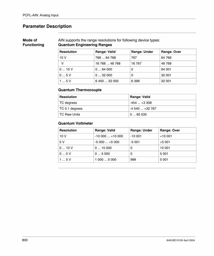
PCFL-AIN: Analog Input
Parameter Description
Mode of Functioning
AIN supports the range resolutions for following device types:Quantum Engineering Ranges
Quantum Thermocouple
Quantum Voltmeter
Resolution Range: Valid Range: Under Range: Over
10 V 768 ... 64 768 767 64 769
V 16 768 ... 48 768 16 767 48 769
0 ... 10 V 0 ... 64 000 0 64 001
0 ... 5 V 0 ... 32 000 0 32 001
1 ... 5 V 6 400 ... 32 000 6 399 32 001
Resolution Range: Valid
TC degrees -454 ... +3 308
TC 0.1 degrees -4 540 ... +32 767
TC Raw Units 0 ... 65 535
Resolution Range: Valid Range: Under Range: Over
10 V -10 000 ... +10 000 -10 001 +10 001
5 V -5 000 ... +5 000 -5 001 +5 001
0 ... 10 V 0 ... 10 000 0 10 001
0 ... 5 V 0 ... 5 000 0 5 001
1 ... 5 V 1 000 ... 5 000 999 5 001
800 840USE10100 April 2004

PCFL-AIN: Analog Input
Parameter Block (Middle Node)
The length of the AIN parameter block is 14 registers.
Output Status
Register Content
Displayed Input from a 3x register
First implied Reserved
Second implied Output status
Third implied Input status
Fourth and fifth implied Scale 100% engineering units
Sixth and seventh implied Scale 0% engineering units
Eighth and ninth implied Manual input
10th and 11th implied Auto input
12th and 13th implied Output
Bit Function
1...5 Not used
6 1 = with TC PSQRT, invalid: in extrapolation range, PSQRT not used
7 1 = input out of range
8 1 = echo under range from input module
9 1 = echo over range from input module
10 1 = invalid output mode selected
11 1 = invalid Engineering Units
12 ... 16 Standard output bits (flags)
840USE10100 April 2004 801

PCFL-AIN: Analog Input
Input Status
Quantum Engineering Ranges
Quantum Thermocouple
Quantum Voltmeter
Bit Function
1 ... 3 Standard input bits (flags)
4 ... 8 Ranges (see following tables)
9 1 = process square root on raw input
10 1 = manual scaling mode0 = auto scaling mode
11 1 = extrapolate over-/under-range for auto mode0 = clamp over-/under-range for auto mode
12 ... 16 Not used
Bit
4 5 6 7 8 Range
0 1 0 0 0 +/- 10V
0 1 0 0 1 +/- 5V
0 1 0 1 0 0 ... 10 V
0 1 0 1 1 0 ... 5 V
0 1 1 0 0 1 ... 5 V
Bit
4 5 6 7 8 Range
0 1 1 0 1 TC degrees
0 1 1 1 0 TC 0.1 degrees
0 1 1 1 1 TC raw units
Bit
4 5 6 7 8 Range
1 0 0 0 0 +/- 10V
1 0 0 1 0 +/- 5V
1 0 1 0 0 0 ... 10 V
1 0 1 1 0 0 ... 5 V
1 1 0 0 0 1 ... 5 V
Note: Bit 4 in this register is nonstandard use.
802 840USE10100 April 2004

840USE10100 April 2004
121
PCFL-ALARM: Central Alarm HandlerAt a Glance
Introduction This chapter describes the subfunction PCFL-Alarm.
What's in this Chapter?
This chapter contains the following topics:
Topic Page
Short Description 804
Representation: PCFL - ALRM - Central Alarm Handler for a P(v) Input 805
Parameter Description 806
803

PCFL-ALARM: Central Alarm Handler
Short Description
Function Description
The ALARM function gives you a central block for alarm handling where you can set high (H), low (L), high high (HH), and low low (LL) limits on a process variable.ALARM lets you specify� A choice of normal or deviation operating mode� Whether to use H/L or both H/L and HH/LL limits� Whether or not to use deadband (DB) around the limits
Note: This instruction is a subfunction of the PCFL instruction. It belongs to the category Signal Processing.
804 840USE10100 April 2004

PCFL-ALARM: Central Alarm Handler
Representation: PCFL - ALRM - Central Alarm Handler for a P(v) Input
Symbol Representation of the instruction
Parameter Description
CONTROL INPUT OPERATION SUCCESSFUL
ERROR
ALRM
parameterblock
PCFL
#16
Parameters State RAM Reference
Data Type Meaning
Top input 0x, 1x None ON = enables specified process control function
ALRM(top node)
Selection of the subfunction ALARM
parameter block(middle node)
4x INT, UINT, WORD
First in a block of contiguous holding registers where the parameters for the specified subfunction are storedFor more information, see Parameter Block (Middle Node), p. 806.
16(bottom node)
INT, UINT Length of parameter block for subfunction ALARM (can not be changed)
Top output 0x None ON = operation successful
Bottom output 0x None ON = error
840USE10100 April 2004 805

PCFL-ALARM: Central Alarm Handler
Parameter Description
Mode of Functioning
The following operating modes are available.
Parameter Block (Middle Node)
The length of the ALARM parameter block is 16 registers.
Mode Meaning
Normal Operating Mode ALARM operates directly on the input. Normal is the default condition
Deviation Operating Mode
ALARM operates on the change between the current input and the last input.
Deadband When enabled, the DB option is incorporated into the HH/H/LL/L limits. These calculated limits are inclusive of the more extreme range, e.g. if the input has been in the high range, the output remains high and does not transition when the input hits the calculated H limit.
Operations A flag is set when the input or deviation equals or crosses the corresponding limit. If the DB option is used, the HH, H, LL, L limits are adjusted internally for crossed-limit checking and hysteresis.
Note: ALARM automatically tracks the last input, even when you specify normal mode, to facilitate a smooth transition to deviation mode.
Register Content
Displayed and first implied Input registers
Second implied Output status
Third implied Input status
Fourth and fifth implied HH limit value
Sixth and seventh implied H limit value
Eighth and ninth implied L limit value
10th and 11th implied LL limit value
12th and 13th implied Deadband (DB) around limit
14th and 15th implied Last input
806 840USE10100 April 2004

PCFL-ALARM: Central Alarm Handler
Output Status
Input Status
Bit Function
1 ... 4 Not used
5 1 = DB set to negative number
6 1 = deviation mode chosen with DB option
7 1 = LL crossed (x ≤ LL
8 1 = L crossed (x ≤ L or LL < x ≤ L) with HH/LL option set
9 1 = H crossed (x ≥ H or H ≤ x < HH) with HH/LL option set
10 1 = HH crossed (x ≥ HH)
11 1 = invalid limits specified
12 ... 16 Standard output bits (flags)
Bit Function
1 ... 4 Standard input bits (flags)
5 1 = deviation mode0 = normal mode
6 1 = both H/L and HH/LL limits apply
7 1 = DB enabled
8 1 = retain H/L flag when HH/LL limits crossed
9 ... 16 Not used
840USE10100 April 2004 807

PCFL-ALARM: Central Alarm Handler
808 840USE10100 April 2004

840USE10100 April 2004
122
PCFL-AOUT: Analog OutputAt a Glance
Introduction This chapter describes the subfunction PCFL-AOUT.
What's in this Chapter?
This chapter contains the following topics:
Topic Page
Short Description 810
Representation: PCFL - AOUT - Convert Outputs to Values in the 0 through 4095 Range
811
Parameter Description 812
809

PCFL-AOUT: Analog Output
Short Description
Function Description
The AOUT function is an interface for calculated signals for output modules. It converts the signal to a value in the range 0 ... 4 096.
Formula Formula of the AOUT function:
The meaning of the elements:
Note: This instruction is a subfunction of the PCFL instruction. It belongs to the category Signal Processing.
Element Meaning
HEU High Engineering Unit
IN Input
LEU Low Engineering Unit
OUT Output
scale Scale
OUTscale IN LEU–( )×
HEU LEU–( )-------------------------------------------------=
810 840USE10100 April 2004

PCFL-AOUT: Analog Output
Representation: PCFL - AOUT - Convert Outputs to Values in the 0 through 4095 Range
Symbol Representation of the instruction
Parameter Description
CONTROL INPUT OPERATION SUCCESSFUL
ERROR
AOUT
parameterblock
PCFL
#9
Parameters State RAM Reference
Data Type Meaning
Top input 0x, 1x None ON = enables specified process control function
AOUT(top node)
Selection of the subfunction AOUT
parameter block(middle node)
4x INT, UINT First in a block of contiguous holding registers where the parameters for the specified subfunction are storedFor more information, see Parameter Block (Middle Node), p. 812.
9(bottom node)
INT, UINT Length of parameter block for subfunction AOUT (can not be changed)
Top output 0x None ON = operation successful
Bottom output 0x None ON = error
840USE10100 April 2004 811

PCFL-AOUT: Analog Output
Parameter Description
Parameter Block (Middle Node)
The length of the AOUT parameter block is 9 registers.
Output Status
Input Status
Register Content
Displayed and first implied Input in engineering units
Second implied Output status
Third implied Input status
Fourth and fifth implied High engineering units
Sixth and seventh implied Low engineering units
Eighth and ninth implied Output
Bit Function
1 ... 7 Not used
8 1 = clamped low
9 1 = clamped high
10 not used
11 1 = invalid H/L limits
12 ... 16 Standard output bits (flags)
Bit Function
1 ... 4 Standard input bits (flags)
5 ... 16 Not used
812 840USE10100 April 2004

840USE10100 April 2004
123
PCFL-AVER: Average Weighted Inputs CalculateAt a Glance
Introduction This chapter describes the subfunction PCFL-AVER.
What's in this Chapter?
This chapter contains the following topics:
Topic Page
Short Description 814
Representation: PCFL - AVER - Average Weighted Inputs 815
Parameter Description 816
813

PCFL-AVER: Average Weighted Inputs Calculate
Short Description
Function Description
The AVER function calculates the average of up to four weighted inputs.
Formula Formula of the AVER function:
The meaning of the elements:
Note: This instruction is a subfunction of the PCFL instruction. It belongs to the category Advanced Calculation.
Element Meaning
In1 ... In4 Inputs
k Constant
RES Result
w1 ... w4 Weights
RESk w1 In1×( ) w2 In2×( ) w3 In3×( ) w4 In4×( )+ + + +( )
1 w1 w2 w3 w4+ + + +-----------------------------------------------------------------------------------------------------------------------------------------=
814 840USE10100 April 2004

PCFL-AVER: Average Weighted Inputs Calculate
Representation: PCFL - AVER - Average Weighted Inputs
Symbol Representation of the instruction
Parameter Description
CONTROL INPUT OPERATION SUCCESSFUL
ERROR
AVER
parameterblock
PCFL
#24
Parameters State RAM Reference
Data Type Meaning
Top input 0x, 1x None ON = enables specified process control function
AVER(top node)
Selection of the subfunction AVER
parameter block(middle node)
4x INT, UINT First in a block of contiguous holding registers where the parameters for the specified subfunction are storedFor more information, see Parameter Block (Middle Node), p. 816.
24(bottom node)
INT, UINT Length of parameter block for subfunction AVER (can not be changed)
Top output 0x None ON = operation successful
Bottom output 0x None ON = error
840USE10100 April 2004 815

PCFL-AVER: Average Weighted Inputs Calculate
Parameter Description
Parameter Block (Middle Node)
The length of the AVER parameter block is 24 registers.
Output Status
Register Content
Displayed and first implied reserved
Second implied Output status
Third implied Input status
Fourth and fifth implied Value of In1
Sixth and seventh implied Value of Inv2
Eighth and ninth implied Value of In3
10th and 11th implied Value of In4
12th and 13th implied Value of k
14th and 15th implied Value of wv1
16th and 17th implied Value of wv2
18th and 19th implied Value of wv3
20th and 21st implied Value of wv4
22nd and 23rd implied Value of result
Bit Function
1 ... 9 Not used
10 1 = no inputs activated
11 1 = result negative0 = result positive
12 ... 16 Standard output bits (flags)
1 2 3 4 5 6 7 8 9 10 11 12 13 14 15 16
816 840USE10100 April 2004

PCFL-AVER: Average Weighted Inputs Calculate
Input Status
A weight can be used only when its corresponding input is enabled, e.g. the 20th and 21st implied registers (which contain the value of w4) can be used only when the 10th and 11th implied registers (which contain In4) are enabled. The I in the denominator is used only when the constant is enabled.
Bit Function
1 ... 4 Standard input bits (flags)
5 1 = In4 and w4 are used
6 1 = In3 and w3 are used
7 1 = In2 and w2 are used
8 1 = In1 and w1 are used
9 1 = k is active
10 ... 16 Not used
1 2 3 4 5 6 7 8 9 10 11 12 13 14 15 16
840USE10100 April 2004 817

PCFL-AVER: Average Weighted Inputs Calculate
818 840USE10100 April 2004

840USE10100 April 2004
124
PCFL-CALC: Calculated preset formulaAt a Glance
Introduction This chapter describes the subfunction PCFL-CALC.
What's in this Chapter?
This chapter contains the following topics:
Topic Page
Short Description 820
Representation: PCFL - CALC - Calculate Present Formula 821
Parameter Description 822
819
PCFL-CALC: Calculated preset formula
Short Description
Function Description
The CALC function calculates a preset formula with up to four inputs, each characterized in a separate register of the parameter block.
Note: This instruction is a subfunction of the PCFL instruction. It belongs to the category Advanced Calculation.
820 840USE10100 April 2004

PCFL-CALC: Calculated preset formula
Representation: PCFL - CALC - Calculate Present Formula
Symbol Representation of the instruction
Parameter Description
CONTROL INPUT OPERATION SUCCESSFUL
ERROR
CALC
parameterblock
PCFL
#14
Parameters State RAM Reference
Data Type Meaning
Top input 0x, 1x None ON = enables specified process control function
CALC(top node)
Selection of the subfunction CALC
parameter block(middle node)
4x INT, UINT First in a block of contiguous holding registers where the parameters for the specified subfunction are storedFor more information, see Parameter Block (Middle Node), p. 822.
14(bottom node)
INT, UINT Length of parameter block for subfunction CALC (can not be changed)
Top output 0x None ON = operation successful
Bottom output 0x None ON = error
840USE10100 April 2004 821

PCFL-CALC: Calculated preset formula
Parameter Description
Parameter Block (Middle Node)
The length of the CALC parameter block is 14 registers.
Output Status
Register Content
Displayed and first implied Reserved
Second implied Output status
Third implied Input status
Fourth and fifth implied Value of input A
Sixth and seventh implied Value of input B
Eighth and ninth implied Value of input C
10th and 11th implied Value of input D
12th and 13th implied Value of the output
Bit Function
1...10 Not used
11 1 = bad input code chosen
12 ... 16 Standard output bits (flags)
1 2 3 4 5 6 7 8 9 10 11 12 13 14 15 16
822 840USE10100 April 2004

PCFL-CALC: Calculated preset formula
Input Status
Formula Code
Bit Function
1 ... 4 Standard input bits (flags)
5 ... 6 not used
7 ... 10 Formula Code
11 ... 16 Not used
Bit Formula Code
7 8 9 10
0 0 0 1
0 0 1 1
0 1 0 0
0 1 0 1
0 1 1 0
0 1 1 1
1 0 0 0
1 0 0 1
1 0 1 0
1 0 1 1
1 1 0 0
1 1 0 1
1 2 3 4 5 6 7 8 9 10 11 12 13 14 15 16
A B×( ) C D×( )–
A B×( ) C D×( )⁄
A B C× D×( )⁄
A B× C×( ) D⁄
A B× C× D×
A B C D+ + +
A B C D–( )×
A B C⁄( )D
[ ]
A LN× B C⁄( )
A B–( ) C D–( ) LN A B–( ) C D–( )⁄[ ]⁄–
A B⁄( )C D⁄–( )
A B–( ) C D–( )⁄
840USE10100 April 2004 823

PCFL-CALC: Calculated preset formula
824 840USE10100 April 2004

840USE10100 April 2004
125
PCFL-DELAY: Time Delay QueueAt a Glance
Introduction This chapter describes the subfunction PCFL-DELAY.
What's in this Chapter?
This chapter contains the following topics:
Topic Page
Short Description 826
Representation: PCFL - DELY - Time Delay Queue 827
Parameter Description 828
825

PCFL-DELAY: Time Delay Queue
Short Description
Function Description
The DELAY function can be used to build a series of readings for time-delay compensation in the logic. Up to 10 sampling instances can be used to delay an input.
All values are carried along in registers, where register x[0] contains the current sampled input. The 10th delay period does not need to be stored. When the 10th instance in the sequence takes place, the value in register x[9] can be moved directly to the output
A DXDONE message is returned when the calculation is complete. The function can be reset by toggling the first-scan bit.
Note: This instruction is a subfunction of the PCFL instruction. It belongs to the category Signal Processing.
826 840USE10100 April 2004

PCFL-DELAY: Time Delay Queue
Representation: PCFL - DELY - Time Delay Queue
Symbol Representation of the instruction
Parameter Description
CONTROL INPUT OPERATION SUCCESSFUL
ERROR
DELY
parameterblock
PCFL
#32
Parameters State RAM Reference
Data Type Meaning
Top input 0x, 1x None ON = enables specified process control function
DELY(top node)
Selection of the subfunction DELY
parameter block(middle node)
4x INT, UINT First in a block of contiguous holding registers where the parameters for the specified subfunction are storedFor more information, see Parameter Block (Middle Node), p. 828.
32(bottom node)
INT, UINT Length of parameter block for subfunction DELY (can not be changed)
Top output 0x None ON = operation successful
Bottom output 0x None ON = error
840USE10100 April 2004 827

PCFL-DELAY: Time Delay Queue
Parameter Description
Parameter Block (Middle Node)
The length of the DELAY parameter block is 32 registers.
Output Status
Input Status
Register Content
Displayed and first implied Input at time n
Second implied Output status
Third implied Input status
Fourth implied Time register
Fifth implied Reserved
Sixth and seventh implied ∆t (in ms) since last solve
Eighth and ninth implied Solution interval (in ms)
10th and 11th implied x[0] delay
12th and 13th implied x[1] delay
14th and 15th implied x[2] delay
... ...
28th and 29th implied x[9] delay
30th and 31st implied Output registers
Bit Function
1...3 Not used
4 1 = k out of range
5 ... 8 Count of registers left to be initialized
9 ... 16 Standard output bits (flags)
1 2 3 4 5 6 7 8 9 10 11 12 13 14 15 16
Bit Function
1 ... 4 Standard input bits (flags)
5 ... 8 Time Delay ≤ 10
9 ... 11 Echo number of registers left to be initialized
12 ... 16 Not used
1 2 3 4 5 6 7 8 9 10 11 12 13 14 15 16
828 840USE10100 April 2004

840USE10100 April 2004
126
PCFL-EQN: Formatted Equation CalculatorAt a Glance
Introduction This chapter describes the subfunction PCFL-EQN.
What's in this Chapter?
This chapter contains the following topics:
Topic Page
Short Description 830
Representation: PCFL - EQN - Formatted Equation Calculator 831
Parameter Description 832
829

PCFL-EQN: Formatted Equation Calculator
Short Description
Function Description
The EQN function is a formatted equation calculator. You must define the equation in the parameter block with various codes that specify operators, input selection and inputs.EQN is used for equations that have four or fewer variables but do not fit into the CALC format. It complements the CALC function by letting you input an equation with floating point and integer inputs as well as operators.
Note: This instruction is a subfunction of the PCFL instruction. It belongs to the category Advanced Calculation.
830 840USE10100 April 2004
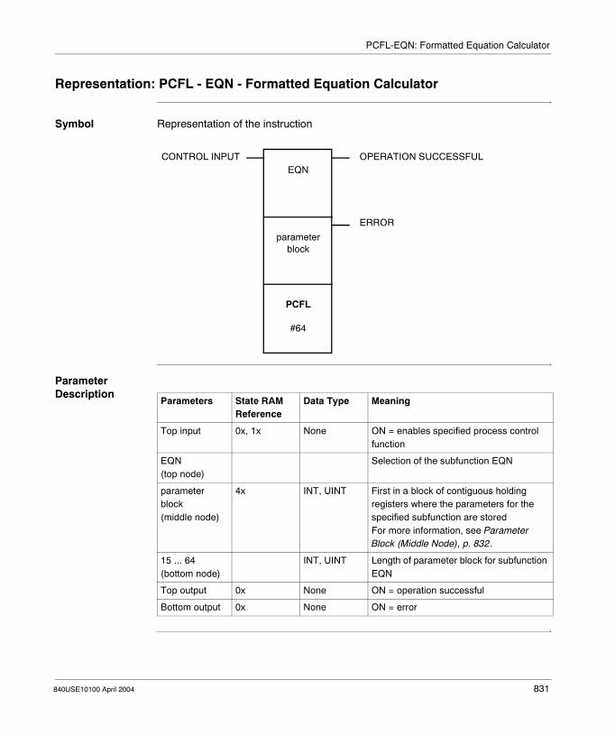
PCFL-EQN: Formatted Equation Calculator
Representation: PCFL - EQN - Formatted Equation Calculator
Symbol Representation of the instruction
Parameter Description
CONTROL INPUT OPERATION SUCCESSFUL
ERROR
EQN
parameterblock
PCFL
#64
Parameters State RAM Reference
Data Type Meaning
Top input 0x, 1x None ON = enables specified process control function
EQN(top node)
Selection of the subfunction EQN
parameter block(middle node)
4x INT, UINT First in a block of contiguous holding registers where the parameters for the specified subfunction are storedFor more information, see Parameter Block (Middle Node), p. 832.
15 ... 64(bottom node)
INT, UINT Length of parameter block for subfunction EQN
Top output 0x None ON = operation successful
Bottom output 0x None ON = error
840USE10100 April 2004 831

PCFL-EQN: Formatted Equation Calculator
Parameter Description
Parameter Block (Middle Node)
The length of the EQN parameter block can be as high as 64 registers.
Output Status
Register Content
Displayed and first implied Reserved
Second implied Output status
Third implied Input status
Fourth and fifth implied Variable A
Sixth and seventh implied Variable B
Eighth and ninth implied Variable C
10th and 11th implied Variable D
12th and 13th implied Output
14th implied First formula code
15th implied Second possible formula code
... ...
63rd implied Last possible formula code
Bit Function
1 Stack error
2...3 Not used
4 ... 8 Code of last error logged
9 1 = bad operator selection code
10 1 = EQN not fully programmed
11 1 = bad input code chosen
12 ... 16 Standard output bits (flags)
1 2 3 4 5 6 7 8 9 10 11 12 13 14 15 16
832 840USE10100 April 2004

PCFL-EQN: Formatted Equation Calculator
Input Status
Formula Code Each formula code in the EQN function defines either an input selection code or an operator selection code.Formula Code (Parameter Block)
Input Selection
Bit Function
1 ... 4 Standard input bits (flags)
5 1 = Degree/radian option for trigonometry
6 ... 8 not used
9 ... 16 Equation size for display in Concept
1 2 3 4 5 6 7 8 9 10 11 12 13 14 15 16
Bit Function
1 ... 4 Not used
5 ... 8 Definition of input selection
9 ... 11 Not used
12 ... 16 Definition of operator selection
Bit Input Selection
5 6 7 8
0 0 0 0 Use operator selection
0 0 0 1 Float input
0 0 1 1 16-bit integer
1 0 0 0 Variable A
1 0 0 1 Variable B
1 0 1 0 Variable C
1 0 1 1 Variable D
1 2 3 4 5 6 7 8 9 10 11 12 13 14 15 16
840USE10100 April 2004 833

PCFL-EQN: Formatted Equation Calculator
Operator Selection
Bit Operator Selection
12 13 14 15 16
0 0 0 0 0 No operation
0 0 0 0 1 Absolute value
0 0 0 1 0 Addition
0 0 0 1 1 Division
0 0 1 0 0 Exponent
0 0 1 1 1 LN (natural logarithm)
0 1 0 0 0 G (logarithm)
0 1 0 0 1 Multiplication
0 1 0 1 0 Negation
0 1 0 1 1 Power
0 1 1 0 0 Square root
0 1 1 0 1 Subtraction
0 1 1 1 0 Sine
0 1 1 1 1 Cosine
1 0 0 0 0 Tangent
1 0 0 0 1 Arcsine
1 0 0 1 0 Arccosine
1 0 0 1 1 Arctangent
834 840USE10100 April 2004

840USE10100 April 2004
127
PCFL-INTEG: Integrate Input at Specified IntervalAt a Glance
Introduction This chapter describes the subfunction PCFL-INTEG.
What's in this Chapter?
This chapter contains the following topics:
Topic Page
Short Description 836
Representation: PCFL - INTG - Integrate Input at Specified Interval 837
Parameter Description 838
835

PCFL-INTEG: Integrate Input at Specified Interval
Short Description
Function Description
The INTEG function is used to integrate over a specified time interval. No protection against integral wind-up is provided in this function. INTEG is time-dependent, e.g. if you are integrating at an input value of 1/sec, it matters whether it operates over one second (in which case the result is 1) or over one minute (in which case the result is 60).You can set flags to either initialize or restart the function after an undetermined down-time, and you can reset the integral sum if you wish. If you set the initialize flag, you must specify a reset value (zero or the last output in case of power failure), and calculations will be skipped for one sample.The function returns a DXDONE message when the operation is complete.
Note: This instruction is a subfunction of the PCFL instruction. It belongs to the category Signal Processing.
836 840USE10100 April 2004

PCFL-INTEG: Integrate Input at Specified Interval
Representation: PCFL - INTG - Integrate Input at Specified Interval
Symbol Representation of the instruction
Parameter Description
CONTROL INPUT OPERATION SUCCESSFUL
ERROR
INTG
parameterblock
PCFL
#16
Parameters State RAM Reference
Data Type Meaning
Top input 0x, 1x None ON = enables specified process control function
INTG(top node)
Selection of the subfunction INTEG
parameter block(middle node)
4x INT, UINT First in a block of contiguous holding registers where the parameters for the specified subfunction are storedFor more information, see Parameter Block (Middle Node), p. 838.
16(bottom node)
INT, UINT Length of parameter block for subfunction INTEG (can not be changed)
Top output 0x None ON = operation successful
Bottom output 0x None ON = error
840USE10100 April 2004 837

PCFL-INTEG: Integrate Input at Specified Interval
Parameter Description
Parameter Block (Middle Node)
The length of the INTEG parameter block is 16 registers.
Output Status
Input Status
Register Content
Displayed and first implied Current Input
Second implied Output status
Third implied Input status
Fourth implied Time register
Fifth implied Reserved
Sixth and seventh implied ∆t (in ms) since last solve
Eighth and ninth implied Solution interval (in ms)
10th and 11th implied Last input
12th and 13th implied Reset value
14th and 15th implied Result
Bit Function
1...8 Not used
9 ... 16 Standard output bits (flags)
1 2 3 4 5 6 7 8 9 10 11 12 13 14 15 16
Bit Function
1 ... 4 Standard input bits (flags)
5 Reset sum
6 ... 16 Not used
1 2 3 4 5 6 7 8 9 10 11 12 13 14 15 16
838 840USE10100 April 2004

840USE10100 April 2004
128
PCFL-KPID: Comprehensive ISA Non Interacting PIDAt a Glance
Introduction This chapter describes the subfunction PCFL-KPID.
What's in this Chapter?
This chapter contains the following topics:
Topic Page
Short Description 840
Representation: PCFL - KPID - Comprehensive ISA Non-Interacting Proportional-Integral-Derivative
841
Parameter Description 842
839

PCFL-KPID: Comprehensive ISA Non Interacting PID
Short Description
Function Description
The KPID function offers a superset of the functionality of the PID function, with additional features that include:� A gain reduction zone� A separate register for bumpless transfer when the integral term is not used� A reset mode� An external set point for cascade control� Built-in velocity limiters for set point changes and changes to a manual output� A variable derivative filter constant� Optional expansion of anti-reset wind-up limits
Note: This instruction is a subfunction of the PCFL instruction. It belongs to the category Regulatory Control.
840 840USE10100 April 2004

PCFL-KPID: Comprehensive ISA Non Interacting PID
Representation: PCFL - KPID - Comprehensive ISA Non-Interacting Proportional-Integral-Derivative
Symbol Representation of the instruction
Parameter Description
CONTROL INPUT OPERATION SUCCESSFUL
ERROR
KPID
parameterblock
PCFL
#64
Parameters State RAM Reference
Data Type Meaning
Top input 0x, 1x None ON = enables specified process control function
KPID(top node)
Selection of the subfunction KPID
parameter block(middle node)
4x INT, UINT First in a block of contiguous holding registers where the parameters for the specified subfunction are storedFor more information, see Parameter Block (Middle Node), p. 842.
64(bottom node)
INT, UINT Length of parameter block for subfunction KPID (can not be changed)
Top output 0x None ON = operation successful
Bottom output 0x None ON = error
840USE10100 April 2004 841

PCFL-KPID: Comprehensive ISA Non Interacting PID
Parameter Description
Parameter Block (Middle Node)
The length of the KPID parameter block is 64 registers.
Register Content
General Parameters
Displayed and first implied Live input, x
Second implied Output Status, Register 1
Third implied Output Status, Register 2
Fourth implied Reserved
Fifth implied Input Status
Input Parameters
Sixth and seventh implied Proportional rate, KP
Eighth and ninth implied Reset time, TI
10th and 11th implied Derivative action time, TD
12th and 13th implied Delay time constant, TD1
14th and 15th implied Gain reduction zone, GRZ
16th and 17th implied Gain reduction in GRZ, KGRZ
18th and 19th implied Limit rise of manual set point value
20th and 21st implied Limit rise of manual output
22nd and 23rd implied High limit for Y
24th and 25th implied Low limit for Y
26th and 27th implied Expansion for anti-reset wind-up limits
Inputs 28th and 29th implied External set point for cascade
30th and 31st implied Manual set point
32nd and 33rd implied Manual Y
34th and 35th implied Reset for Y
36th and 37th implied Bias
842 840USE10100 April 2004
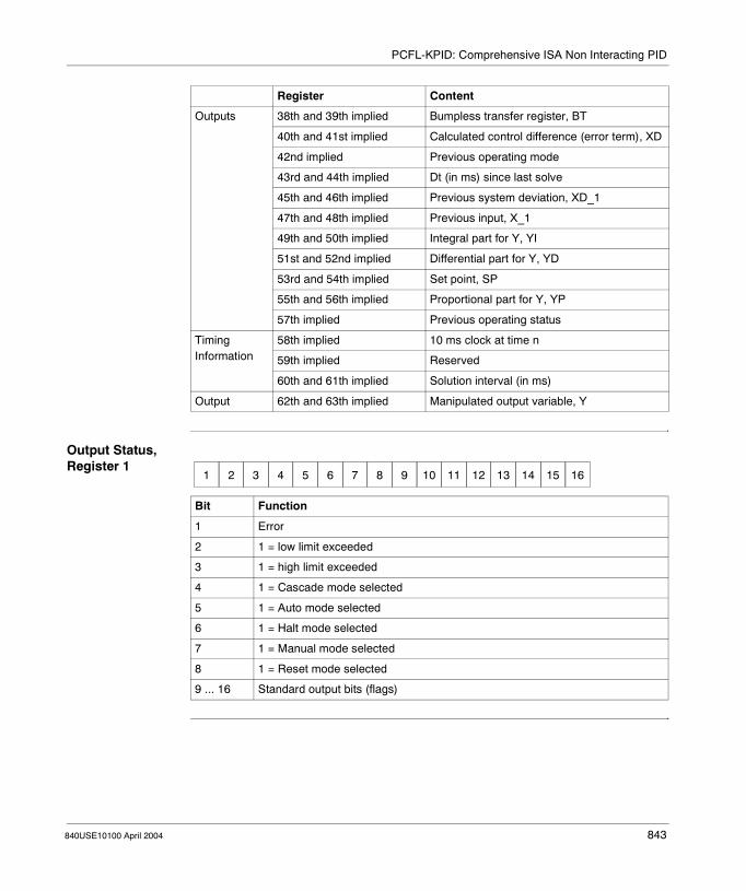
PCFL-KPID: Comprehensive ISA Non Interacting PID
Output Status, Register 1
Outputs 38th and 39th implied Bumpless transfer register, BT
40th and 41st implied Calculated control difference (error term), XD
42nd implied Previous operating mode
43rd and 44th implied Dt (in ms) since last solve
45th and 46th implied Previous system deviation, XD_1
47th and 48th implied Previous input, X_1
49th and 50th implied Integral part for Y, YI
51st and 52nd implied Differential part for Y, YD
53rd and 54th implied Set point, SP
55th and 56th implied Proportional part for Y, YP
57th implied Previous operating status
Timing Information
58th implied 10 ms clock at time n
59th implied Reserved
60th and 61th implied Solution interval (in ms)
Output 62th and 63th implied Manipulated output variable, Y
Register Content
Bit Function
1 Error
2 1 = low limit exceeded
3 1 = high limit exceeded
4 1 = Cascade mode selected
5 1 = Auto mode selected
6 1 = Halt mode selected
7 1 = Manual mode selected
8 1 = Reset mode selected
9 ... 16 Standard output bits (flags)
1 2 3 4 5 6 7 8 9 10 11 12 13 14 15 16
840USE10100 April 2004 843
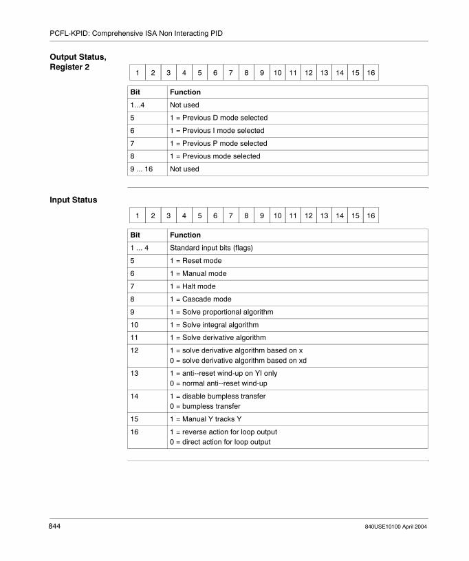
PCFL-KPID: Comprehensive ISA Non Interacting PID
Output Status, Register 2
Input Status
Bit Function
1...4 Not used
5 1 = Previous D mode selected
6 1 = Previous I mode selected
7 1 = Previous P mode selected
8 1 = Previous mode selected
9 ... 16 Not used
1 2 3 4 5 6 7 8 9 10 11 12 13 14 15 16
Bit Function
1 ... 4 Standard input bits (flags)
5 1 = Reset mode
6 1 = Manual mode
7 1 = Halt mode
8 1 = Cascade mode
9 1 = Solve proportional algorithm
10 1 = Solve integral algorithm
11 1 = Solve derivative algorithm
12 1 = solve derivative algorithm based on x0 = solve derivative algorithm based on xd
13 1 = anti--reset wind-up on YI only0 = normal anti--reset wind-up
14 1 = disable bumpless transfer0 = bumpless transfer
15 1 = Manual Y tracks Y
16 1 = reverse action for loop output0 = direct action for loop output
1 2 3 4 5 6 7 8 9 10 11 12 13 14 15 16
844 840USE10100 April 2004

840USE10100 April 2004
129
PCFL-LIMIT: Limiter for the PvAt a Glance
Introduction This chapter describes the subfunction PCFL-LIMIT.
What's in this Chapter?
This chapter contains the following topics:
Topic Page
Short Description 846
Representation: PCFL - LIMIT - Limiter for the P(v) 847
Parameter Description 848
845

PCFL-LIMIT: Limiter for the Pv
Short Description
Function Description
The LIMIT function limits the input to a range between a specified high and low value. If the high or low limit is reached, the function sets an H or L flag and clamps the output.
LIMIT returns a DXDONE message when the operation is complete.
Note: This instruction is a subfunction of the PCFL instruction. It belongs to the category Signal Processing.
846 840USE10100 April 2004

PCFL-LIMIT: Limiter for the Pv
Representation: PCFL - LIMIT - Limiter for the P(v)
Symbol Representation of the instruction
Parameter Description
CONTROL INPUT OPERATION SUCCESSFUL
ERROR
LIMIT
parameterblock
PCFL
#9
Parameters State RAM Reference
Data Type Meaning
Top input 0x, 1x None ON = enables specified process control function
LIMIT(top node)
Selection of the subfunction LIMIT
parameter block(middle node)
4x INT, UINT First in a block of contiguous holding registers where the parameters for the specified subfunction are storedFor more information, see Parameter Block (Middle Node), p. 848.
9(bottom node)
INT, UINT Length of parameter block for subfunction LIMIT (can not be changed)
Top output 0x None ON = operation successful
Bottom output 0x None ON = error
840USE10100 April 2004 847

PCFL-LIMIT: Limiter for the Pv
Parameter Description
Parameter Block (Middle Node)
The length of the LIMIT parameter block is 9 registers.
Output Status
Input Status
Register Content
Displayed and first implied Current input
Second implied Output status
Third implied Input status
Fourth and fifth implied Low limit
Sixth and seventh implied High Limit
Eighth implied Output register
Bit Function
1...8 Not used
9 1 = input < low limit
10 1 = input > high limit
11 1 = invalid high/low limits (e.g., low ≥ high
12 ... 16 Standard output bits (flags)
1 2 3 4 5 6 7 8 9 10 11 12 13 14 15 16
Bit Function
1 ... 4 Standard input bits (flags)
5 ... 16 Not used
1 2 3 4 5 6 7 8 9 10 11 12 13 14 15 16
848 840USE10100 April 2004

840USE10100 April 2004
130
PCFL-LIMV: Velocity Limiter for Changes in the PvAt a Glance
Introduction This chapter describes the subfunction PCFL-LIMV.
What's in this Chapter?
This chapter contains the following topics:
Topic Page
Short Description 850
Representation: PCFL - LIMV - Velocity Limiter for Changes in the P(v) 851
Parameter Description 852
849

PCFL-LIMV: Velocity Limiter for Changes in the Pv
Short Description
Function Description
The LIMV function limits the velocity of change in the input variable between a specified high and low value. If the high or low limit is reached, the function sets an H or L flag and clamps the output.LIMV returns a DXDONE message when the operation is complete.
Note: This instruction is a subfunction of the PCFL instruction. It belongs to the category Signal Processing.
850 840USE10100 April 2004

PCFL-LIMV: Velocity Limiter for Changes in the Pv
Representation: PCFL - LIMV - Velocity Limiter for Changes in the P(v)
Symbol Representation of the instruction
Parameter Description
CONTROL INPUT OPERATION SUCCESSFUL
ERROR
LIMV
parameterblock
PCFL
#14
Parameters State RAM Reference
Data Type Meaning
Top input 0x, 1x None ON = enables specified process control function
LIMV(top node)
Selection of the subfunction LIMV
parameter block(middle node)
4x INT, UINT First in a block of contiguous holding registers where the parameters for the specified subfunction are stored(For expanded and detailed information please see Parameter Block (Middle Node), p. 852.)
14(bottom node)
INT, UINT Length of parameter block for subfunction LIMV (can not be changed)
Top output 0x None ON = operation successful
Bottom output 0x None ON = error
840USE10100 April 2004 851

PCFL-LIMV: Velocity Limiter for Changes in the Pv
Parameter Description
Parameter Block (Middle Node)
The length of the LIMV parameter block is 14 registers.
Output Status
Input Status
Register Content
Displayed and first implied Input register
Second implied Output status
Third implied Input status
Fourth implied Time register
Fifth implied Reserved
Sixth and seventh implied ∆t (in ms) since last solve
Eighth and ninth implied Solution interval (in ms)
10th and 11th implied Velocity limit / sec
12th and 13th implied Result
Bit Function
1...5 Not used
6 1 = negative velocity limit
7 1 = input < low limit
8 1 = input > high limit
9 ... 16 Standard output bits (flags)
1 2 3 4 5 6 7 8 9 10 11 12 13 14 15 16
Bit Function
1 ... 4 Standard input bits (flags)
5 ... 16 Not used
1 2 3 4 5 6 7 8 9 10 11 12 13 14 15 16
852 840USE10100 April 2004

840USE10100 April 2004
131
PCFL-LKUP: Look-up TableAt a Glance
Introduction This chapter describes the subfunction PCFL-LKUP.
What's in this Chapter?
This chapter contains the following topics:
Topic Page
Short Description 854
Representation: PCFL - LKUP - Look-up Table 855
Parameter Description 856
853
PCFL-LKUP: Look-up Table
Short Description
Function Description
The LKUP function establishes a look-up table using a linear algorithm to interpolate between points. LKUP can handle variable point intervals and variable numbers of points.
Note: This instruction is a subfunction of the PCFL instruction. It belongs to the category Signal Processing.
854 840USE10100 April 2004

PCFL-LKUP: Look-up Table
Representation: PCFL - LKUP - Look-up Table
Symbol Representation of the instruction
Parameter Description
CONTROL INPUT OPERATION SUCCESSFUL
ERROR
LKUP
parameterblock
PCFL
#39
Parameters State RAM Reference
Data Type Meaning
Top input 0x, 1x None ON = enables specified process control function
LKUP(top node)
Selection of the subfunction LKUP
parameter block(middle node)
4x INT, UINT First in a block of contiguous holding registers where the parameters for the specified subfunction are stored(For more information, please see Parameter Block (Middle Node), p. 857.)
39(bottom node)
INT, UINT Length of parameter block for subfunction LKUP (can not be changed)
Top output 0x None ON = operation successful
Bottom output 0x None ON = error
840USE10100 April 2004 855

PCFL-LKUP: Look-up Table
Parameter Description
Mode of Functioning
The LKUP function establishes a look-up table using a linear algorithm to interpolate between points. LKUP can handle variable point intervals and variable numbers of points.
If the input (x) is outside the specified range of points, the output (y) is clamped to the corresponding output y0 or yn. If the specified parameter block length is too small or if the number of points is out of range, the function does not check the xn because the information from that pointer is invalid.
Points to be interpolated are determined by a binary search algorithm starting near the center of x data. The search is valid for x1 < x < xn. The variable x may occur multiple times with the same value, the value chosen from the look-up table is the first instance found.For example, if the table is:
then an input of 30.0 finds the first instance of 30.0 and assigns 3.0 as the output. An input of 31.0 would assign the value 3.55 as the output.No sorting is done on the contents of the lookup table. Independent variable table values should be entered in ascending order to prevent unreachable gaps in the table.
The function returns a DXDONE message when the operation is complete.
x y
10.0 1.0
20.0 2.0
30.0 3.0
30.0 3.5
40.0 4.0
856 840USE10100 April 2004

PCFL-LKUP: Look-up Table
Parameter Block (Middle Node)
The length of the LKUP parameter block is 39 registers.
Output Status
Input Status
Register Content
Displayed and first implied Input
Second implied Output status
Third implied Input status
Fourth implied Number of point pairs
Fifth and sixth implied Point x1
Seventh and eighth implied Point y1
Ninth and tenth implied Point x2
11th and 12th implied Point y2
. . . . . .
33rd and 34th implied Point x8
35th and 36th implied Point y8
37th and 38th implied Output
Bit Function
1 ... 9 Not used
10 1 = input clamped, i.e. out of table’s range
11 ! = invalid number of points
12 ... 16 Standard output bits (flags)
1 2 3 4 5 6 7 8 9 10 11 12 13 14 15 16
Bit Function
1 ... 4 Standard input bits (flags)
5 ... 16 Not used
1 2 3 4 5 6 7 8 9 10 11 12 13 14 15 16
840USE10100 April 2004 857

PCFL-LKUP: Look-up Table
858 840USE10100 April 2004

840USE10100 April 2004
132
PCFL-LLAG: First-order Lead/Lag FilterAt a Glance
Introduction This chapter describes the subfunction PCFL-LLAG.
What's in this Chapter?
This chapter contains the following topics:
Topic Page
Short Description 860
Representation: PCFL - LLAG - First-Order Lead/Lag Filter 861
Parameter Description 862
859

PCFL-LLAG: First-order Lead/Lag Filter
Short Description
Function Description
The LLAG function provides dynamic compensation for a known disturbance. It usually appears in a feed-forward algorithm or as a dynamic filter. LLAG passes the input through a filter comprising a lead term (a numerator) and a lag term (a denominator) in the frequency domain, then multiplies it by a gain. Lead, lag, gain, and solution interval must be user-specified.
For best results, use lead and lag terms that are ≥ 4 *∆t. This will ensure sufficient granularity in the output response.
LLAG returns a DXDONE message when the operation completes
Note: This instruction is a subfunction of the PCFL instruction. It belongs to the category Signal Processing.
860 840USE10100 April 2004

PCFL-LLAG: First-order Lead/Lag Filter
Representation: PCFL - LLAG - First-Order Lead/Lag Filter
Symbol Representation of the instruction
Parameter Description
CONTROL INPUT OPERATION SUCCESSFUL
ERROR
LLAG
parameterblock
PCFL
#20
Parameters State RAM Reference
Data Type Meaning
Top input 0x, 1x None ON = enables specified process control function
LLAG(top node)
Selection of the subfunction LLAG
parameter block(middle node)
4x INT, UINT First in a block of contiguous holding registers where the parameters for the specified subfunction are stored(For more information, please see Parameter Block (Middle Node), p. 862.)
20(bottom node)
INT, UINT Length of parameter block for subfunction LLAG (can not be changed)
Top output 0x None ON = operation successful
Bottom output 0x None ON = error
840USE10100 April 2004 861

PCFL-LLAG: First-order Lead/Lag Filter
Parameter Description
Parameter Block (Middle Node)
The length of the LLAG parameter block is 20 registers.
Output Status
Input Status
Register Content
Displayed and first implied Current Input
Second implied Output status
Third implied Input status
Fourth implied Time register
Fifth implied Reserved
Sixth and seventh implied ∆t (in ms) since last solve
Eighth and ninth implied Solution interval (in ms)
10th and 11th implied Last input
12th and 13th implied Lead term
14th and 15th implied Lag term
16th and 17th implied Filter gain
18th and 19th implied Result
Bit Function
1...8 Not used
9 ... 16 Standard output bits (flags)
1 2 3 4 5 6 7 8 9 10 11 12 13 14 15 16
Bit Function
1 ... 4 Standard input bits (flags)
5 ... 16 Not used
1 2 3 4 5 6 7 8 9 10 11 12 13 14 15 16
862 840USE10100 April 2004

840USE10100 April 2004
133
PCFL-MODE: Put Input in Auto or Manual ModeAt a Glance
Introduction This chapter describes the subfunction PCFL-MODE.
What's in this Chapter?
This chapter contains the following topics:
Topic Page
Short Description 864
Representation: PCFL - MODE - Put Input in Auto or Manual Mode 865
Parameter Description 866
863

PCFL-MODE: Put Input in Auto or Manual Mode
Short Description
Function Description
The MODE function sets up a manual or automatic station for enabling and disabling data transfers to the next block. The function acts like a BLKM instruction, moving a value to the output register.
In auto mode, the input is copied to the output. In manual mode, the output is overwritten by a user entry.
MODE returns a DXDONE message when the operation completes.
Note: This instruction is a subfunction of the PCFL instruction. It belongs to the category Signal Processing.
864 840USE10100 April 2004

PCFL-MODE: Put Input in Auto or Manual Mode
Representation: PCFL - MODE - Put Input in Auto or Manual Mode
Symbol Representation of the instruction
Parameter Description
CONTROL INPUT OPERATION SUCCESSFUL
ERROR
MODE
parameterblock
PCFL
#8
Parameters State RAM Reference
Data Type Meaning
Top input 0x, 1x None ON = enables specified process control function
MODE(top node)
Selection of the subfunction MODE
parameter block(middle node)
4x INT, UINT First in a block of contiguous holding registers where the parameters for the specified subfunction are stored(For more information, please see Parameter Block (Middle Node), p. 866.)
8(bottom node)
INT, UINT Length of parameter block for subfunction MODE (can not be changed)
Top output 0x None ON = operation successful
Bottom output 0x None ON = error
840USE10100 April 2004 865

PCFL-MODE: Put Input in Auto or Manual Mode
Parameter Description
Parameter Block (Middle Node)
The length of the MODE parameter block is 8 registers.
Output Status
Input Status
Register Content
Displayed and first implied Input
Second implied Output status
Third implied Input status
Fourth and fifth implied Manual input
Sixth and seventh implied Output register
Bit Function
1 ... 10 Not used
11 Echo mode:1 = manual mode0 = auto mode
12 ... 16 Standard output bits (flags)
1 2 3 4 5 6 7 8 9 10 11 12 13 14 15 16
Bit Function
1 ... 4 Standard input bits (flags)
5 1 = manual mode0 = auto mode
6 ... 16 Not used
1 2 3 4 5 6 7 8 9 10 11 12 13 14 15 16
866 840USE10100 April 2004
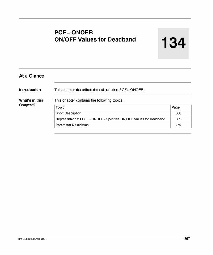
840USE10100 April 2004
134
PCFL-ONOFF: ON/OFF Values for DeadbandAt a Glance
Introduction This chapter describes the subfunction PCFL-ONOFF.
What's in this Chapter?
This chapter contains the following topics:
Topic Page
Short Description 868
Representation: PCFL - ONOFF - Specifies ON/OFF Values for Deadband 869
Parameter Description 870
867

PCFL-ONOFF: ON/OFF Values for Deadband
Short Description
Function Description
The ONOFF function is used to control the output signal between fully ON and fully OFF conditions so that a user can manually force the output ON or OFF. You can control the output via either a direct or reverse configuration:
Manual Override Two bits in the input status register (the third implied register in the parameter block) are used for manual override. When bit 6 is set to 1, manual mode is enforced. In manual mode, a 0 in bit 7 forces the output OFF, and a 1 in bit 7 forces the output ON. The state of bit 7 has meaning only in manual mode.
Note: This instruction is a subfunction of the PCFL instruction. It belongs to the category Regulatory Control.
Configuration IF Input... Then Output...
Direct < (SP - DB) ON
> (SP + DB) OFF
Revers > (SP + DB) ON
< (SP - DB) OFF
868 840USE10100 April 2004

PCFL-ONOFF: ON/OFF Values for Deadband
Representation: PCFL - ONOFF - Specifies ON/OFF Values for Deadband
Symbol Representation of the instruction
Parameter Description
CONTROL INPUT OPERATION SUCCESSFUL
ERROR
ONOFF
parameterblock
PCFL
#14
Parameters State RAM Reference
Data Type Meaning
Top input 0x, 1x None ON = enables specified process control function
ONOFF(top node)
Selection of the subfunction ONOFF
parameter block(middle node)
4x INT, UINT First in a block of contiguous holding registers where the parameters for the specified subfunction are stored(For more information, please see Parameter Block (Middle Node), p. 870.)
14(bottom node)
INT, UINT Length of parameter block for subfunction ONOFF (can not be changed)
Top output 0x None ON = operation successful
Bottom output 0x None ON = error
840USE10100 April 2004 869

PCFL-ONOFF: ON/OFF Values for Deadband
Parameter Description
Parameter Block (Middle Node)
The length of the ONOFF parameter block is 14 registers.
Output Status
Register Content
Displayed and first implied Current Input
Second implied Output status
Third implied Input status
Fourth and fifth implied Set point, SP
Sixth and seventh implied Deadband (DB) around SP
Eighth and ninth implied Fully ON (maximum output)
10th and 11th implied Fully OFF (minimum output)
12th and 13th implied Output, ON or OFF
Bit Function
1 ... 8 Not used
9 1 = DB set to negative number
10 Echo mode:1 = manual override0 = auto mode
11 1 = output set to ON0 = output set to OFF
12 ... 16 Standard output bits (flags)
1 2 3 4 5 6 7 8 9 10 11 12 13 14 15 16
870 840USE10100 April 2004

PCFL-ONOFF: ON/OFF Values for Deadband
Input Status
Bit Function
1 ... 4 Standard input bits (flags)
5 1 = reverse configuration0 = direct configuration
6 1 = manual override0 = auto mode
7 1 = force output ON in manual mode0 = force output OFF in manual mode
8 ... 16 Not used
1 2 3 4 5 6 7 8 9 10 11 12 13 14 15 16
840USE10100 April 2004 871

PCFL-ONOFF: ON/OFF Values for Deadband
872 840USE10100 April 2004

840USE10100 April 2004
135
PCFL-PI: ISA Non Interacting PIAt a Glance
Introduction This chapter describes the subfunction PCFL-PI.
What's in this Chapter?
This chapter contains the following topics:
Topic Page
Short Description 874
Representation: PCFL - PI 875
Parameter Description 876
873

PCFL-PI: ISA Non Interacting PI
Short Description
Function Description
The PI function performs a simple proportional-integral operations using floating point math. It features halt / manual / auto operation modes. It is similar to the PID and KPID functions but does not contain as many options. It is available for higher-speed loops or inner loops in cascade strategies.
Note: This instruction is a subfunction of the PCFL instruction. It belongs to the category Regulatory Control.
874 840USE10100 April 2004

PCFL-PI: ISA Non Interacting PI
Representation: PCFL - PI
Symbol Representation of the instruction
Parameter Description
CONTROL INPUT OPERATION SUCCESSFUL
ERROR
PI
parameterblock
PCFL
#36
Parameters State RAM Reference
Data Type Meaning
Top input 0x, 1x None ON = enables specified process control function
PI(top node)
Selection of the subfunction PI
parameter block(middle node)
4x INT, UINT First in a block of contiguous holding registers where the parameters for the specified subfunction are stored(For more information, please see Parameter Block (Middle Node), p. 876.)
36(bottom node)
INT, UINT Length of parameter block for subfunction PI (can not be changed)
Top output 0x None ON = operation successful
Bottom output 0x None ON = error
840USE10100 April 2004 875

PCFL-PI: ISA Non Interacting PI
Parameter Description
Parameter Block (Middle Node)
The length of the PI parameter block is 36 registers.
Register Content
General Parameters
Displayed and first implied Live input, x
Second implied Output Status
Third implied Error Word
Fourth implied Reserved
Fifth implied Input Status
Inputs Sixth and seventh implied Set point, SP
Eighth and ninth implied Manual output
10th and 11th implied Calculated control difference (error), XD
Outputs 12th implied Previous operating mode
13th and 14th implied Dt (in ms) since last solve
15th and 16th implied Previous system deviation, XD_1
17th and 18th implied Integral part of output Y
19th and 20th implied Previous input, X_1
21st implied Previous operating status
Timing Information
22nd implied 10 ms clock at time n
23rd implied Reserved
24th and 25th implied Solution interval (in ms)
Input Parameters
26th and 27th implied Proportional rate, KP
28th and 29th implied Reset time, TI
30th and 31st implied High limit on output Y
32nd and 33rd implied Low limit on output Y
Output 34th and 35th implied Manipulated variable output, Y
876 840USE10100 April 2004

PCFL-PI: ISA Non Interacting PI
Output Status
Error Word
Error Description
Input Status
Bit Function
1 Error
2 1 = low limit exceeded
3 1 = high limit exceeded
4 ... 8 Not used
9 ... 16 Standard output bits (flags)
1 2 3 4 5 6 7 8 9 10 11 12 13 14 15 16
Bit Function
1...11 Not used
12 ... 16 Error Description
Bit Meaning
12 13 14 15 16
1 0 1 1 0 Negative integral time constant
1 0 1 0 1 High/low limit error (low ≥ high)
1 2 3 4 5 6 7 8 9 10 11 12 13 14 15 16
Bit Function
1 ... 4 Standard input bits (flags)
5 Not used
6 1 = Manual mode
7 1 = Halt mode
8 ... 15 Not used
16 1 = reverse action for loop output0 = direct action for loop output
1 2 3 4 5 6 7 8 9 10 11 12 13 14 15 16
840USE10100 April 2004 877

PCFL-PI: ISA Non Interacting PI
878 840USE10100 April 2004

840USE10100 April 2004
136
PCFL-PID: PID AlgorithmsAt a Glance
Introduction This chapter describes the subfunction PCFL-PID.
What's in this Chapter?
This chapter contains the following topics:
Topic Page
Short Description 880
Representation: PCFL - PID - Algorithms 881
Parameter Description 882
879
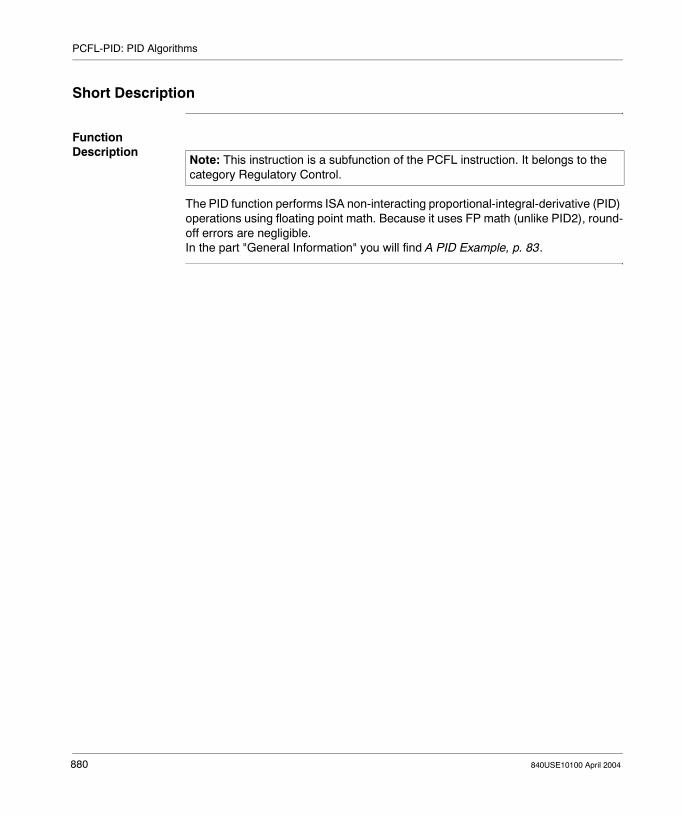
PCFL-PID: PID Algorithms
Short Description
Function Description
The PID function performs ISA non-interacting proportional-integral-derivative (PID) operations using floating point math. Because it uses FP math (unlike PID2), round-off errors are negligible.In the part "General Information" you will find A PID Example, p. 83.
Note: This instruction is a subfunction of the PCFL instruction. It belongs to the category Regulatory Control.
880 840USE10100 April 2004
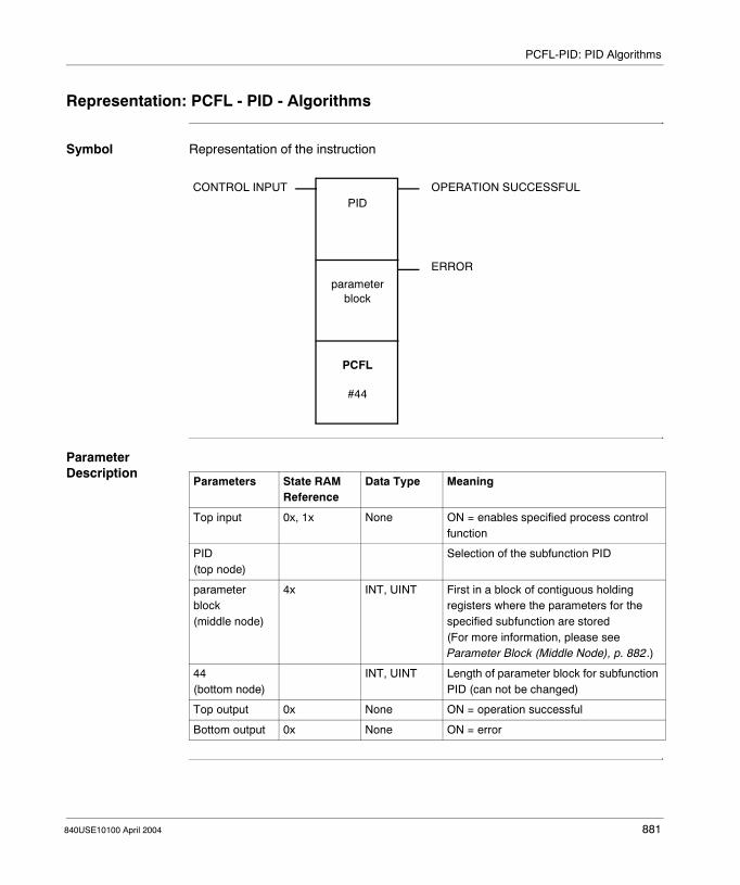
PCFL-PID: PID Algorithms
Representation: PCFL - PID - Algorithms
Symbol Representation of the instruction
Parameter Description
CONTROL INPUT OPERATION SUCCESSFUL
ERROR
PID
parameterblock
PCFL
#44
Parameters State RAM Reference
Data Type Meaning
Top input 0x, 1x None ON = enables specified process control function
PID(top node)
Selection of the subfunction PID
parameter block(middle node)
4x INT, UINT First in a block of contiguous holding registers where the parameters for the specified subfunction are stored(For more information, please see Parameter Block (Middle Node), p. 882.)
44(bottom node)
INT, UINT Length of parameter block for subfunction PID (can not be changed)
Top output 0x None ON = operation successful
Bottom output 0x None ON = error
840USE10100 April 2004 881

PCFL-PID: PID Algorithms
Parameter Description
Parameter Block (Middle Node)
The length of the KPID parameter block is 44 registers.
Register Content
General Parameters
Displayed and first implied Live input, x
Second implied Output Status
Third implied Error Word
Fourth implied Reserved
Fifth implied Input Status
Inputs Sixth and seventh implied Set point, SP
Eighth and ninth implied Manual output
10th and 11th implied Summing junction, Bias
Outputs 12th and 13th implied Error, XD
14th implied Previous operating mode
15th and 16th implied Elapsed time (in ms) since last solve
17th and 18th implied Previous system deviation, XD_1
19th and 20th implied Previous input, X_1
21st and 22nd implied Integral part of output Y, YI
23rd and 24th implied Differential part of output Y, YD
25th and 26th implied Proportional part of output Y, YP
27th implied Previous operating status
Timing Information
28th implied Current time
29th implied Reserved
Inputs 30th and 31st implied Solution interval (in ms)
34th and 35th implied Reset time, TI
36th and 37th implied Derivative action time, TD
38th and 39th implied High limit on output Y
40th and 41st implied Low limit on output Y
42nd and 43rd implied Manipulated control output, Y
882 840USE10100 April 2004

PCFL-PID: PID Algorithms
Output Status
Error Word
Error Description
Bit Function
1 Error
2 1 = low limit exceeded
3 1 = high limit exceeded
4 ... 8 Not used
9 ... 16 Standard output bits (flags)
1 2 3 4 5 6 7 8 9 10 11 12 13 14 15 16
Bit Function
1...11 Not used
12 ... 16 Error Description
Bit Meaning
12 13 14 15 16
1 0 1 1 1 Negative derivative time constant
1 0 1 1 0 Negative integral time constant
1 0 1 0 1 High/low limit error (low ≥ high)
1 2 3 4 5 6 7 8 9 10 11 12 13 14 15 16
840USE10100 April 2004 883
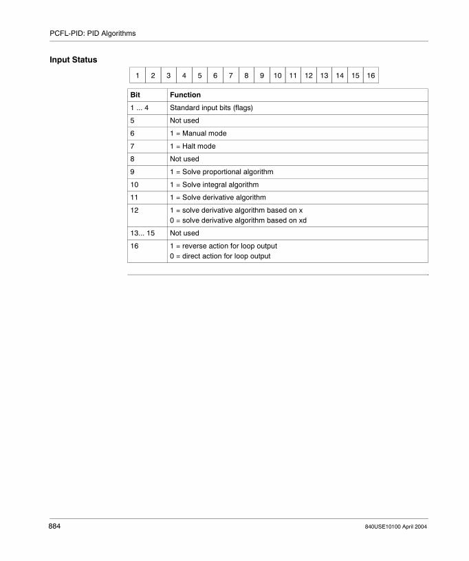
PCFL-PID: PID Algorithms
Input Status
Bit Function
1 ... 4 Standard input bits (flags)
5 Not used
6 1 = Manual mode
7 1 = Halt mode
8 Not used
9 1 = Solve proportional algorithm
10 1 = Solve integral algorithm
11 1 = Solve derivative algorithm
12 1 = solve derivative algorithm based on x0 = solve derivative algorithm based on xd
13... 15 Not used
16 1 = reverse action for loop output0 = direct action for loop output
1 2 3 4 5 6 7 8 9 10 11 12 13 14 15 16
884 840USE10100 April 2004

840USE10100 April 2004
137
PCFL-RAMP: Ramp to Set Point at a Constant RateAt a Glance
Introduction This chapter describes the subfunction PCFL-RAMP.
What's in this Chapter?
This chapter contains the following topics:
Topic Page
Short Description 886
Representation: PCFL - RAMP - Ramp to Set Point at Constant Rate 887
Parameter Description 888
885

PCFL-RAMP: Ramp to Set Point at a Constant Rate
Short Description
Function Description
The RAMP function allows you to ramp up linearly to a target set point at a specified approach rate. You need to specify:� The target set point, in the same units as the contents of the input register are
specified� The sampling rate� A positive rate toward the target set point, negative rates are illegal
The direction of the ramp depends on the relationship between the target set point and the input, i.e. if x < SP, the ramp is up; if x > SP, the ramp is down.
You may use a flag to initialize after an undetermined down-time. The function will store a new sample, then wait for one cycle to collect the second sample. Calculations will be skipped for one cycle and the output will be left as is, after which the ramp will resume.
RAMP terminates when the entire ramping operation is complete (over multiple scans) and returns a DXDONE message.
Starting the Ramp
The following steps need to be done when starting the ramp (up/down) and each and every time you need to start or restart the ramp.
Note: This instruction is a subfunction of the PCFL instruction. It belongs to the category Signal Processing.
Step Action
1 Set bit 1 of the standard input bits to "1" (third implied register of the parameter block).
2 Retoggle the top input (enable input) to the instruction. Ramp will now start to ramp up/down from the initial value previously configured up/down to the previously configured setpoint. Monitor the 12th implied register of the parameter block for floating point value of the ramp value in progress.
886 840USE10100 April 2004

PCFL-RAMP: Ramp to Set Point at a Constant Rate
Representation: PCFL - RAMP - Ramp to Set Point at Constant Rate
Symbol Representation of the instruction
Parameter Description
CONTROL INPUT OPERATION SUCCESSFUL
ERROR
RAMP
parameterblock
PCFL
#14
Parameters State RAM Reference
Data Type Meaning
Top input 0x, 1x None ON = enables specified process control function
RAMP(top node)
Selection of the subfunction RAMP
parameter block(middle node)
4x INT, UINT First in a block of contiguous holding registers where the parameters for the specified subfunction are stored(For more information, please see Parameter Block (Middle Node), p. 888.)
14(bottom node)
INT, UINT Length of parameter block for subfunction RAMP (can not be changed)
Top output 0x None ON = operation successful
Bottom output 0x None ON = error
840USE10100 April 2004 887
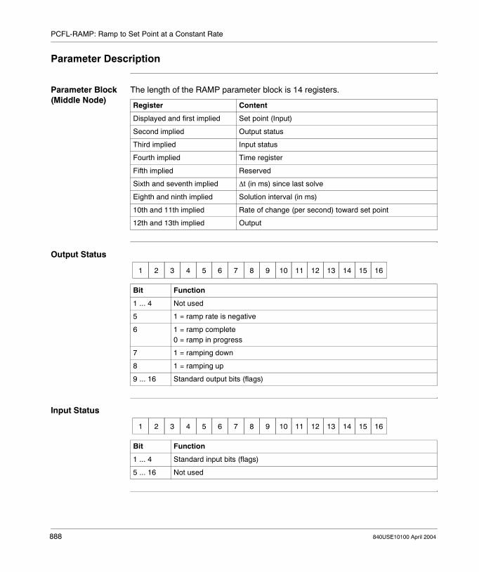
PCFL-RAMP: Ramp to Set Point at a Constant Rate
Parameter Description
Parameter Block (Middle Node)
The length of the RAMP parameter block is 14 registers.
Output Status
Input Status
Register Content
Displayed and first implied Set point (Input)
Second implied Output status
Third implied Input status
Fourth implied Time register
Fifth implied Reserved
Sixth and seventh implied ∆t (in ms) since last solve
Eighth and ninth implied Solution interval (in ms)
10th and 11th implied Rate of change (per second) toward set point
12th and 13th implied Output
Bit Function
1 ... 4 Not used
5 1 = ramp rate is negative
6 1 = ramp complete0 = ramp in progress
7 1 = ramping down
8 1 = ramping up
9 ... 16 Standard output bits (flags)
1 2 3 4 5 6 7 8 9 10 11 12 13 14 15 16
Bit Function
1 ... 4 Standard input bits (flags)
5 ... 16 Not used
1 2 3 4 5 6 7 8 9 10 11 12 13 14 15 16
888 840USE10100 April 2004

PCFL-RAMP: Ramp to Set Point at a Constant Rate
Top Output (Operation Succesfull)
The top output of the PCFL subfunction RAMP goes active at each successive discrete ramp step up/down. It happens so fast that it appears to be solidly on. This top output should NOT be used as "Ramp done bit".
Bit 6 of the output status (second impied register of the parameter block) should be monitored as "Ramp done bit".
840USE10100 April 2004 889

PCFL-RAMP: Ramp to Set Point at a Constant Rate
890 840USE10100 April 2004

840USE10100 April 2004
138
PCFL-RATE: Derivative Rate Calculation over a Specified TimemeAt a Glance
Introduction This chapter describes the subfunction PCFL-RATE.
What's in this Chapter?
This chapter contains the following topics:
Topic Page
Short Description 892
Representation: PCFL - RATE - Derivative Rate Calculation Over a Specified Time
893
Parameter Description 894
891

PCFL-RATE: Derivative Rate Calculation over a Specified Time
Short Description
Function Description
The RATE function calculates the rate of change over the last two input values. If you set an initialization flag, the function records a sample and sets the appropriate flags.
If a divide-by-zero operation is attempted, the function returns a DXERROR message.
It returns a DXDONE message when the operation completes successfully.
Note: This instruction is a subfunction of the PCFL instruction. It belongs to the category Signal Processing.
892 840USE10100 April 2004

PCFL-RATE: Derivative Rate Calculation over a Specified Time
Representation: PCFL - RATE - Derivative Rate Calculation Over a Specified Time
Symbol Representation of the instruction
Parameter Description
CONTROL INPUT OPERATION SUCCESSFUL
ERROR
RATE
parameterblock
PCFL
#14
Parameters State RAM Reference
Data Type Meaning
Top input 0x, 1x None ON = enables specified process control function
RATE(top node)
Selection of the subfunction RATE
parameter block(middle node)
4x INT, UINT First in a block of contiguous holding registers where the parameters for the specified subfunction are stored(For more information, please see Parameter Block (Middle Node), p. 894.)
14(bottom node)
INT, UINT Length of parameter block for subfunction RATE (can not be changed)
Top output 0x None ON = operation successful
Bottom output 0x None ON = error
840USE10100 April 2004 893

PCFL-RATE: Derivative Rate Calculation over a Specified Time
Parameter Description
Parameter Block (Middle Node)
The length of the RATE parameter block is 14 registers.
Output Status
Input Status
Register Content
Displayed and first implied Current input
Second implied Output status
Third implied Input status
Fourth implied Time register
Fifth implied Reserved
Sixth and seventh implied ∆t (in ms) since last solve
Eighth and ninth implied Solution interval (in ms)
10th and 11th implied Last input
12th and 13th implied Result
Bit Function
1 ... 8 Not used
9 ... 16 Standard output bits (flags)
1 2 3 4 5 6 7 8 9 10 11 12 13 14 15 16
Bit Function
1 ... 4 Standard input bits (flags)
5 ... 16 Not used
1 2 3 4 5 6 7 8 9 10 11 12 13 14 15 16
894 840USE10100 April 2004

840USE10100 April 2004
139
PCFL-RATIO: Four Station Ratio ControllerAt a Glance
Introduction This chapter describes the subfunction PCFL-RATIO.
What's in this Chapter?
This chapter contains the following topics:
Topic Page
Short Description 896
Representation: PCFL - RATIO - Four-Station Ratio Controller 897
Parameter Description 898
895

PCFL-RATIO: Four Station Ratio Controller
Short Description
Function Description
The RATIO function provides a four-station ratio controller. Ratio control can be used in applications where one or more raw ingredients are dependent on a primary ingredient. The primary ingredient is measured, and the measurement is converted to engineering units via an AIN function. The converted value is used to set the target for the other ratioed inputs.
Outputs from the ratio controller can provide set points for other controllers. They can also be used in an open loop structure for applications where feedback is not required.
Note: This instruction is a subfunction of the PCFL instruction. It belongs to the category Regulatory Control.
896 840USE10100 April 2004

PCFL-RATIO: Four Station Ratio Controller
Representation: PCFL - RATIO - Four-Station Ratio Controller
Symbol Representation of the instruction
Parameter Description
CONTROL INPUT 0PERATION SUCCESSFUL
ERROR
RATIO
parameterblock
PCFL
#20
Parameters State RAM Reference
Data Type Meaning
Top input 0x, 1x None ON = enables specified process control function
RATIO(top node)
Selection of the subfunction RATIO
parameter block(middle node)
4x INT, UINT First in a block of contiguous holding registers where the parameters for the specified subfunction are storedFor more information. please see Parameter Block (Middle Node), p. 898.)
20(bottom node)
INT, UINT Length of parameter block for subfunction RATIO (can not be changed)
Top output 0x None ON = operation successful
Bottom output 0x None ON = error
840USE10100 April 2004 897

PCFL-RATIO: Four Station Ratio Controller
Parameter Description
Parameter Block (Middle Node)
The length of the RATIO parameter block is 20 registers.
Output Status
Register Content
Displayed and first implied Live input
Second implied Output status
Third implied Input status
Fourth and fifth implied Ratio for input 1
Sixth and seventh implied Ratio for input 2
Eighth and ninth implied Ratio for input 3
10th and 11th implied Ratio for input 4
12th and 13th implied Output for input 1
14th and 15th implied Output for input 2
16th and 17th implied Output for input 3
18th and 19th implied Output for input 4
Bit Function
1 ... 9 Not used
10 1 = parameter(s) out of range
11 1 = no inputs activated
12 ... 16 Standard output bits (flags)
1 2 3 4 5 6 7 8 9 10 11 12 13 14 15 16
898 840USE10100 April 2004

PCFL-RATIO: Four Station Ratio Controller
Input Status
Bit Function
1 ... 4 Standard input bits (flags)
5 1= input 4 active
6 1= input 3 active
7 1= input 2 active
8 1= input 1 active
9 ... 16 Not used
1 2 3 4 5 6 7 8 9 10 11 12 13 14 15 16
840USE10100 April 2004 899

PCFL-RATIO: Four Station Ratio Controller
900 840USE10100 April 2004

840USE10100 April 2004
140
PCFL-RMPLN: Logarithmic Ramp to Set PointAt a Glance
Introduction This chapter describes the subfunction PCFL-RMPLN.
What's in this Chapter?
This chapter contains the following topics:
Topic Page
Short Description 902
Representation: PCFL - RMPLN - Logarithmic Ramp to Set Point 903
Parameter Description 904
901

PCFL-RMPLN: Logarithmic Ramp to Set Point
Short Description
Function Description
The RMPLN function allows you to ramp up logarithmically to a target set point at a specified approach rate. At each successive call, it calculates the output until it is within a specified deadband (DB). DB is necessary because the incremental distance the ramp crosses decreases with each solve.
You need to specify:� The target set point, in the same units as the contents of the input register are
specified� The sampling rate� The time constant used for the logarithmic ramp, which is the time it takes to
reach 63.2% of the new set point
For best results, use a t that is ≥4 *∆t. This will ensure sufficient granularity in the output response.
You may use a flag to initialize after an undetermined down-time. The function will store a new sample, then wait for one cycle to collect the second sample. Calculations will be skipped for one cycle and the output will be left as is, after which the ramp will resume.
RMPLN terminates when the input reaches the target set point + the specified DB and returns a DXDONE message.
Note: This instruction is a subfunction of the PCFL instruction. It belongs to the category Signal Processing.
902 840USE10100 April 2004
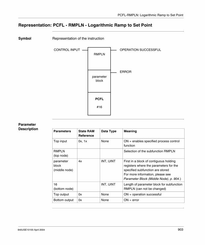
PCFL-RMPLN: Logarithmic Ramp to Set Point
Representation: PCFL - RMPLN - Logarithmic Ramp to Set Point
Symbol Representation of the instruction
Parameter Description
CONTROL INPUT OPERATION SUCCESSFUL
ERROR
RMPLN
parameterblock
PCFL
#16
Parameters State RAM Reference
Data Type Meaning
Top input 0x, 1x None ON = enables specified process control function
RMPLN(top node)
Selection of the subfunction RMPLN
parameter block(middle node)
4x INT, UINT First in a block of contiguous holding registers where the parameters for the specified subfunction are storedFor more information, please see Parameter Block (Middle Node), p. 904.)
16(bottom node)
INT, UINT Length of parameter block for subfunction RMPLN (can not be changed)
Top output 0x None ON = operation successful
Bottom output 0x None ON = error
840USE10100 April 2004 903

PCFL-RMPLN: Logarithmic Ramp to Set Point
Parameter Description
Parameter Block (Middle Node)
The length of the RMPLN parameter block is 16 registers.
Output Status
Input Status
Register Content
Displayed and first implied Set point (Input)
Second implied Output status
Third implied Input status
Fourth implied Time register
Fifth implied Reserved
Sixth and seventh implied ∆t (in ms) since last solve
Eighth and ninth implied Solution interval (in ms)
10th and 11th implied Time constant, τ, (per second) of exponential ramp toward the target set point
12th and 13th implied DB (in engineering units)
14th and 15th implied Output
Bit Function
1 ... 4 Not used
5 1 = DB or τ set to negative units
6 1 = ramp complete0 = ramp in progress
7 1 = ramping down
8 1 = ramping up
9 ... 16 Standard output bits (flags)
1 2 3 4 5 6 7 8 9 10 11 12 13 14 15 16
Bit Function
1 ... 4 Standard input bits (flags)
5 ... 16 Not used
1 2 3 4 5 6 7 8 9 10 11 12 13 14 15 16
904 840USE10100 April 2004
840USE10100 April 2004
141
PCFL-SEL: Input SelectionAt a Glance
Introduction This chapter describes the subfunction PCFL-SEL.
What's in this Chapter?
This chapter contains the following topics:
Topic Page
Short Description 906
Representation: PCFL - SEL - High/Low/Average Input Selection 907
Parameter Description 908
905

PCFL-SEL: Input Selection
Short Description
Function Description
The SEL function compares up to four inputs and makes a selection based upon either the highest, lowest, or average value. You choose the inputs to be compared and the comparison criterion. The output is a copy of the selected input.
SEL returns a DXDONE message when the operation is complete.
Note: This instruction is a subfunction of the PCFL instruction. It belongs to the category Signal Processing.
906 840USE10100 April 2004

PCFL-SEL: Input Selection
Representation: PCFL - SEL - High/Low/Average Input Selection
Symbol Representation of the instruction
Parameter Description
CONTROL INPUT OPERATION SUCCESSFUL
ERROR
SEL
parameterblock
PCFL
#14
Parameters State RAM Reference
Data Type Meaning
Top input 0x, 1x None ON = enables specified process control function
SEL(top node)
Selection of the subfunction SEL
parameter block(middle node)
4x INT, UINT First in a block of contiguous holding registers where the parameters for the specified subfunction are stored(For more information, please see Parameter Block (Middle Node), p. 908.)
14(bottom node)
INT, UINT Length of parameter block for subfunction SEL (can not be changed)
Top output 0x None ON = operation successful
Bottom output 0x None ON = error
840USE10100 April 2004 907

PCFL-SEL: Input Selection
Parameter Description
Parameter Block (Middle Node)
The length of the SEL parameter block is 14 registers.
Output Status
Register Content
Displayed and first implied Reserved
Second implied Output status
Third implied Input status
Fourth and fifth implied Input 1
Sixth and seventh implied Input 2
Eighth and ninth implied Input 3
10th and 11th implied Input 4
12th and 13th implied Output
Bit Function
1 ... 9 Not used
10 Invalid selection modes
11 No inputs selected
12 ... 16 Standard output bits (flags)
1 2 3 4 5 6 7 8 9 10 11 12 13 14 15 16
908 840USE10100 April 2004

PCFL-SEL: Input Selection
Input Status
Selection mode
Bit Function
1 ... 4 Standard input bits (flags)
5 1 = enable input 10 = disable input 1
6 1 = enable input 20 = dyeable input 2
7 1 = enable input 30 = dyeable input 3
8 1 = enable input 40 = dyeable input 4
9 ... 10 Selection mode
11 ... 16 Not used
Bit Meaning
9 10
0 0 Select average
0 1 Select high
1 0 Select low
1 1 reserved / invalid
1 2 3 4 5 6 7 8 9 10 11 12 13 14 15 16
840USE10100 April 2004 909

PCFL-SEL: Input Selection
910 840USE10100 April 2004

840USE10100 April 2004
142
PCFL-TOTAL: Totalizer for Metering FlowAt a Glance
Introduction This chapter describes the subfunction PCFL-TOTAL.
What's in this Chapter?
This chapter contains the following topics:
Topic Page
Short Description 912
Representation: PCFL - TOTAL - Totalizer for Metering Flow 913
Parameter Description 914
911

PCFL-TOTAL: Totalizer for Metering Flow
Short Description
Function Description
The TOTAL function provides a material totalizer for batch processing reagents. The input signal contains the units of weight or volume per unit of time. The totalizer integrates the input over time.
The algorithm reports three outputs:� The integration sum� The remainder left to meter in� The valve output (in engineering units).
Note: This instruction is a subfunction of the PCFL instruction. It belongs to the category Regulatory Control.
912 840USE10100 April 2004

PCFL-TOTAL: Totalizer for Metering Flow
Representation: PCFL - TOTAL - Totalizer for Metering Flow
Symbol Representation of the instruction
Parameter Description
CONTROL INPUT OPERATION SUCCESSFUL
ERROR
TOTAL
parameterblock
PCFL
#28
Parameters State RAM Reference
Data Type Meaning
Top input 0x, 1x None ON = enables specified process control function
TOTAL(top node)
Selection of the subfunction TOTAL
parameter block(middle node)
4x INT, UINT First in a block of contiguous holding registers where the parameters for the specified subfunction are stored(For more information, please see Parameter Block (Middle Node), p. 915.)
28(bottom node)
INT, UINT Length of parameter block for subfunction TOTAL (can not be changed)
Top output 0x None ON = operation successful
Bottom output 0x None ON = error
840USE10100 April 2004 913

PCFL-TOTAL: Totalizer for Metering Flow
Parameter Description
Mode of Functioning
The function uses up to three different set points: � A trickle flow set point� A target set point� An auxiliary trickle flow set point
The target set point is for the full amount to be metered in. Here the output will be turned OFF.
The trickle flow set point is the cut-off point when the output should be decreased from full flow to a percentage of full flow so that the target set point is reached with better granularity.The auxiliary trickle flow set point is optional. It is used to gain another level of granularity. If this set point is enabled, the output is reduced further to 10% of the trickle output.
The totalizer works from zero as a base point. The set point must be a positive value
In normal operation, the valve output is set to 100% flow when the integrated value is below the trickle flow set point. When the sum crosses the trickle flow set point, the valve flow becomes a programmable percentage of full flow. When the sum reaches the desired target set point, the valve output is set to 0% flow.
Set points can be relative or absolute. With a relative set point, the deviation between the last summation and the set point is used. Otherwise, the summation is used in absolute comparison to the set point.
There is a halt option to stop the system from integrating.
When the operation has finished, the output summation is retained for future use. You have the option of clearing this sum. In some applications, it is important to save the sum, e.g. if the meters or load cells cannot handle the full batch in one charge and measurements are split up, if there are several tanks to fill for a batch and you want to keep track of batch and production sums.
914 840USE10100 April 2004

PCFL-TOTAL: Totalizer for Metering Flow
Parameter Block (Middle Node)
The length of the TOTAL parameter block is 28 registers.
Output Status
Register Content
Displayed and first implied Live input
Second implied Output status
Third implied Input status
Fourth implied Time register
Fifth implied Reserved
Sixth and seventh implied ∆t (in ms) since last solve
Eighth and ninth implied Solution interval (in ms)
10th and 11th implied Last input, X_1
12th and 13th implied Reset value
14th and 15th implied Set point, target
16th and 17th implied Set point, trickle flow
18th and 19th implied % of full flow for trickle flow set point
20th and 21st implied Full flow
22nd and 23rd implied Remaining amount to SP
24th and 25th implied Resulting sum
26th and 27th implied Output for final control element
Bit Function
1 ... 2 Not used
3 ... 4 0 0 = OFF0 1 = trickle flow1 0 = full flow
5 1 = operation done
6 1 = totalizer running
7 1 = overshoot past set point by more than 5%
8 1 = parameter(s) out of range
9 ... 16 Standard output bits (flags)
1 2 3 4 5 6 7 8 9 10 11 12 13 14 15 16
840USE10100 April 2004 915
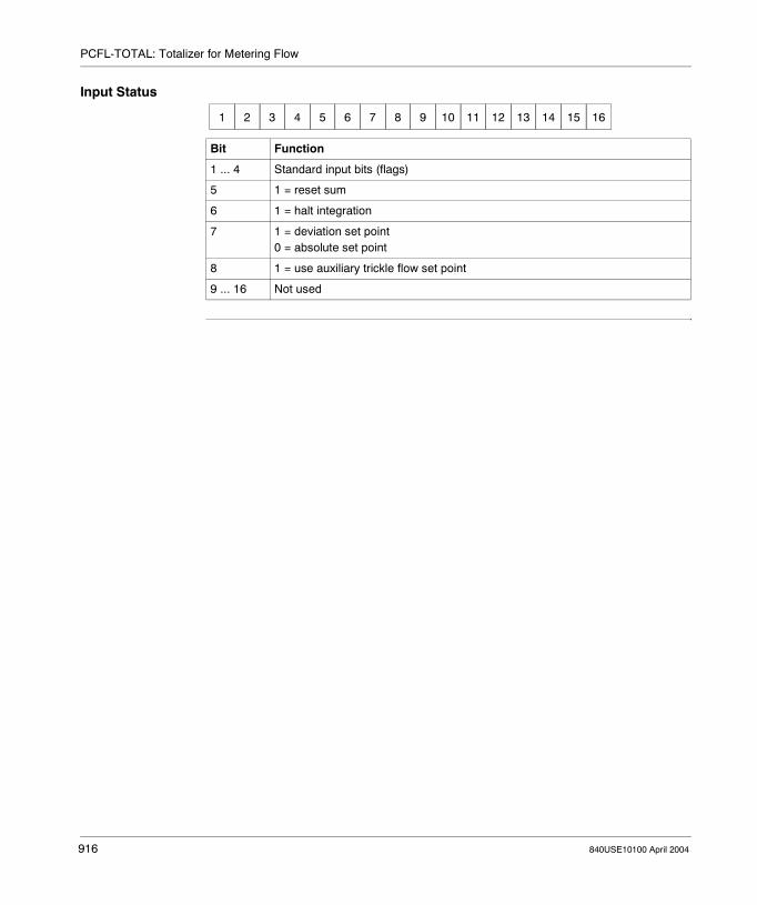
PCFL-TOTAL: Totalizer for Metering Flow
Input Status
Bit Function
1 ... 4 Standard input bits (flags)
5 1 = reset sum
6 1 = halt integration
7 1 = deviation set point0 = absolute set point
8 1 = use auxiliary trickle flow set point
9 ... 16 Not used
1 2 3 4 5 6 7 8 9 10 11 12 13 14 15 16
916 840USE10100 April 2004

840USE10100 April 2004
143
PEER: PEER TransactionAt a Glance
Introduction This chapter describes the instruction PEER.
What's in this Chapter?
This chapter contains the following topics:
Topic Page
Short Description 918
Representation: PEER - Modbus II Identical Transfer 919
Parameter Description 920
917

PEER: PEER Transaction
Short Description
Function Description
The S975 Modbus II Interface option modules use two loadable function blocks: MBUS and PEER. The PEER instruction can initiate identical message transactions with as many as 16 devices on Modbus II at one time. In a PEER transaction, you may only write register data.
Note: This instruction is only available if you have unpacked and installed the DX Loadables. For further information, see Installation of DX Loadables, p. 109.
918 840USE10100 April 2004

PEER: PEER Transaction
Representation: PEER - Modbus II Identical Transfer
Symbol Representation of the instruction
Parameter Description
CONTROL INPUT
REPEAT
COMPLETE
ACTIVE
ERROR
control block
data block
PEER
lengthLength: 1 - 249
Parameters State RAM Reference
Data Type Meaning
Top input 0x, 1x None Enable MBUS transaction
Middle input 0x, 1x None Repeat transaction in same scan
control block(top node)
4x INT, UINT, WORD
First of 19 contiguous registers in the PEER control block(For more information, please see Control Block (Top Node), p. 920.)
data block(middle node)
4x INT, UINT First register in a data block to be transmitted by the PEER function
length(bottom node)
INT, UINT Length, i.e. the number of holding registers, of the data block; range: 1 ... 249.
Top output 0x None Transaction complete
Middle output 0x None Transaction in progress or new transaction starting
Bottom output 0x None Error detected in transaction
840USE10100 April 2004 919

PEER: PEER Transaction
Parameter Description
Control Block (Top Node)
The 4x register entered in the top node is the first of 19 contiguous registers in the PEER control block.
Register Function
Displayed Indicates the status of the transactions at each device, the leftmost bit being the status of device #1 and the rightmost bit the status of device #16: 0 = OK, 1 = transaction error
First implied Defines the reference to the first 4x register to be written to in the receiving device; a 0 in this field is an invalid value and will produce an error (the bottom output will go ON)
Second implied Time allowed for a transaction to be completed before an error is declared; expressed as a multiple of 10 ms, e.g. 100 indicates 1,000 ms; the default timeout is 250 ms
Third implied The Modbus port 3 address of the first of the receiving devices; address range: 1 ... 255 (0 = no transaction requested)
Fourth implied The Modbus port 3 address of the second of the receiving devices; address range: 1 ... 255 (0 = no transaction requested)
. . . . . .
18th implied The Modbus port 3 address of the 16th of the receiving devices (address range: 1 ... 255)
920 840USE10100 April 2004

840USE10100 April 2004
144
PID2: Proportional Integral DerivativeAt a Glance
Introduction This chapter describes the instruction PID2.
What's in this Chapter?
This chapter contains the following topics:
Topic Page
Short Description 922
Representation: PID2 - Proportional/Integral/Derivative 923
Detailed Description 924
Parameter Description 927
Run Time Errors 932
921
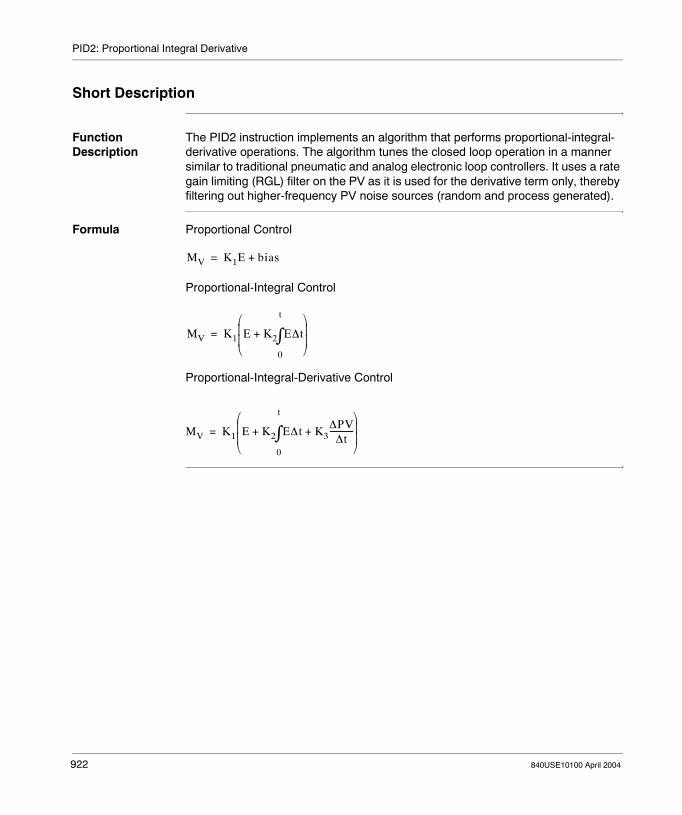
PID2: Proportional Integral Derivative
Short Description
Function Description
The PID2 instruction implements an algorithm that performs proportional-integral-derivative operations. The algorithm tunes the closed loop operation in a manner similar to traditional pneumatic and analog electronic loop controllers. It uses a rate gain limiting (RGL) filter on the PV as it is used for the derivative term only, thereby filtering out higher-frequency PV noise sources (random and process generated).
Formula Proportional Control
Proportional-Integral Control
Proportional-Integral-Derivative Control
MV K1E bias+=
MV K1 E K2 E∆t
0
t
∫+
=
MV K1 E K2 E∆t K3∆PV
∆t------------+
0
t
∫+
=
922 840USE10100 April 2004
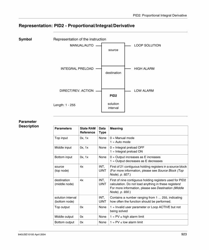
PID2: Proportional Integral Derivative
Representation: PID2 - Proportional/Integral/Derivative
Symbol Representation of the instruction
Parameter Description
MANUAL/AUTO
INTEGRAL PRELOAD
DIRECT/REV. ACTION
LOOP SOLUTION
HIGH ALARM
LOW ALARM
source
destination
PID2
solutioninterval
Length: 1 - 255
Parameters State RAM Reference
Data Type
Meaning
Top input 0x, 1x None 0 = Manual mode1 = Auto mode
Middle input 0x, 1x None 0 = Integral preload OFF1 = Integral preload ON
Bottom input 0x, 1x None 0 = Output increases as E increases1 = Output decreases as E decreases
source(top node)
4x INT, UINT
First of 21 contiguous holding registers in a source block(For more information, please see Source Block (Top Node), p. 927.)
destination(middle node)
4x INT, UINT
First of nine contiguous holding registers used for PID2 calculation. Do not load anything in these registers!For more information, please see Destination (MIddle Node), p. 930.)
solution interval(bottom node)
INT, UINT
Contains a number ranging from 1 ... 255, indicating how often the function should be performed.
Top output 0x None 1 = Invalid user parameter or Loop ACTIVE but not being solved
Middle output 0x None 1 = PV ≥ high alarm limit
Bottom output 0x None 1 = PV ≤ low alarm limit
840USE10100 April 2004 923

PID2: Proportional Integral Derivative
Detailed Description
Block Diagram
Xn-1 ++
Xn
DerivativeContribution
Xn
-+PV RGL
4x13
RGL Ts
(4y + 6)/8
60(RGL - 1)K3
Zn
-+
-+SP
E E
ProportionalContribution
100PB
(4x1 - 4x2)(4x11 - 4x12)
x 4095
++
+Bias
4x8
In-+
GE
Mn-1IntegralContribution
IntegralFeedback
M
OutputClamp Mn
4x174x18
4x2
+- K2 T2
600000
++
InIn-14y + 3, + 4, + 5
(4y + 6)/8
InIn-1
PreloadMode
Qn
Wn
IntegralClamp
FIOC4x16
TIOC4x20
∆
Pv∆ x∆
I
924 840USE10100 April 2004

PID2: Proportional Integral Derivative
The elements in the block diagram have the following meaning:
Element Meaning
E Error, expressed in raw analog units
SP Set point, in the range 0 ... 4095
PV Process variable, in the range 0 ... 4095
x Filtered PV
K2 Integral mode gain constant, expressed in 0.01 min-1
K3 Derivative mode gain constant, expressed in hundredths of a minute
RGL Rate gain limiting filter constant, in the range 2 ... 30
Ts Solution time, expressed in hundredths of a second
PB Proportional band, in the range 5 ... 500%
bias Loop output bias factor, in the range 0 ... 4095
M Loop output
GE Gross error, the proportional-derivative contribution to the loop output
Z Derivative mode contribution to GE
Qn Unbiased loop output
F Feedback value, in the range 0 ... 4095
I Integral mode contribution to the loop output
Ilow Anti-reset-windup low SP, in the range 0 ... 4095
Ihigh Anti-reset-windup high SP, in the range 0 ... 4095
K1 100/PB
Note: The integral mode contribution calculation actually integrates the difference of the output and the integral sum, this is effectively the same as integrating the error.
840USE10100 April 2004 925

PID2: Proportional Integral Derivative
Proportional Control
With proportional-only control (P), you can calculate the manipulated variable by multiplying error by a proportional constant, K1, then adding a bias. See Formula, p. 922.
However, process conditions in most applications are changed by other system variables so that the bias does not remain constant; the result is offset error, where PV is constantly offset from the SP. This condition limits the capability of proportional-only control.
Proportional-Integral Control
To eliminate this offset error without forcing you to manually change the bias, an integral function can be added to the control equation. See Formula, p. 922.Proportional-integral control (PI) eliminates offset by integrating E as a function of time. K1 is the integral constant expressed as rep/min. As long as E ≠ 0, the integrator increases (or decreases) its value, adjusting Mv. This continues until the offset error is eliminated.
Proportional-Integral-Derivative Control
You may want to add derivative functionality to the control equation to minimize the effects of frequent load changes or to override the integral function in order to get to the SP condition more quickly. See Formula, p. 922.
Proportional-integral-derivative (PID) control can be used to save energy in the process or as a safety valve in the event of a sudden, unexpected change in process flow. K3 is the derivative time constant expressed as min. DPV is the change in the process variable over a time period of ∆t.
Example An example to PID2 level control you will find in PID2 Level Control Example.
Note: The value in the integral term (in registers 4y + 3, 4y + 4, and 4y + 5) is always used, even when the integral mode is not enabled. Using this value is necessary to preserve bumpless transfer between modes. If you wish to disable bumpless transfer, these three registers must be cleared.In manual mode setpoint changes will not take effect unless the above three registers are cleared and the mode is switched back to automatic. The transfer will not be bumpless.
926 840USE10100 April 2004

PID2: Proportional Integral Derivative
Parameter Description
Source Block (Top Node)
The 4x register entered in the top node is the first of 21 contiguous holding registers in a source block. The contents of the fifth ... eighth implied registers determine whether the operation will be P, PI, or PID:
The source block comprises the following register assignments:
Operation Fifth Implied Sixth Implied Seventh Implied Eighth Implied
P ON ON
PI ON ON
PID ON ON ON
Register Name Content
Displayed Scaled PV Loaded by the block each time it is scanned; a linear scaling is done on register 4x + 13 using the high and low ranges from registers 4x + 11 and 4x + 12:Scaled PV = (4x13 / 4095) * (4x11 - 4x12) + 4x12
First implied
SP You must specify the set point in engineering units; the value must be < value in the 11th implied register and > value in the 12th implied register
Second implied
Mv Loaded by the block every time the loop is solved; it is clamped to a range of 0 ... 4095, making the output compatible with an analog output module; the manipulated variable register may be used for further CPU calculations such as cascaded loops
Third implied
High Alarm Limit Load a value in this register to specify a high alarm for PV (at or above SP); enter the value in engineering units within the range specified in the 11th and 12th implied registers
Fourth implied
Low Alarm Limit Load a value in this register to specify a low alarm for PV (at or below SP); enter the value in engineering units within the range specified in the 11th and 12th implied registers
Fifth implied
Proportional Band
Load this register with the desired proportional constant in the range 5 ... 500; the smaller the number, the larger the proportional contribution; a valid number is required in this register for PID2 to operate
Sixth implied
Reset Time Constant
Load this register to add integral action to the calculation; enter a value between 0000 ... 9999 to represent a range of 00.00 ... 99.99 repeats/min; the larger the number, the larger the integral contribution; a value > 9999 stops the PID2 calculation
840USE10100 April 2004 927

PID2: Proportional Integral Derivative
Seventh implied
Rate Time Constant
Load this register to add derivative action to the calculation; enter a value between 0000 ... 9999 to represent a range of 00.00 ... 99.99 min; the larger the number, the larger the derivative contribution; a value > 9999 stops the PID2 calculation
Eighth implied
Bias Load this register to add a bias to the output; the value must be between 000 .... 4095, and added directly to Mv, whether the integral term is enabled or not
Ninth implied
High Integral Windup Limit
Load this register with the upper limit of the output value (between 0 ... 4095) where the anti-reset windup takes effect; the updating of the integral sum is stopped if it goes above this value (this is normally 4095)
10th implied
Low Integral Windup Limit
Load this register with the lower limit of the output value (between 0 ... 4095) where the anti-reset windup takes effect (this is normally 0)
11th implied
High Engineering Range
Load this register with the highest value for which the measurement device is spanned, e.g. if a resistance temperature device ranges from 0 ... 500 degrees C, the high engineering range value is 500; the range must be given as a positive integer between 0001 ... 9999, corresponding to the raw analog input 4095
12th implied
Low Engineering Range
Load this register with the lowest value for which the measurement device is spanned; the range must be given as a positive integer between 0 ... 9998, and it must be less than the value in the 11th implied register; it corresponds to the raw analog input 0
13th implied
Raw Analog Measurement
The logic program loads this register with PV; the measurement must be scaled and linear in the range 0 ... 4095
14th implied
Pointer to Loop Counter Register
The value you load in this register points to the register that counts the number of loops solved in each scan; the entry is determined by discarding the most significant digit in the register where the controller will count the loops solved/scan, e.g., if the PLC does the count in register 41236, load 1236 into the 14th implied register; the same value must be loaded into the 14th implied register in every PID2 block in the logic program
15th implied
Maximum Number of Loops
Solved In a Scan: If the 14th implied register contains a non-zero value, you may load a value in this register to limit the number of loops to be solved in one scan
Register Name Content
928 840USE10100 April 2004

PID2: Proportional Integral Derivative
16th implied
Pointer To Reset Feedback Input:
The value you load in this register points to the holding register that contains the value of feedback (F); drop the 4 from the feedback register and enter the remaining four digits in this register; integration calculations depend on the F value being should F vary from 0 ... 4095
17th implied
Output Clamp - High
The value entered in this register determines the upper limit of Mv (this is normally 4095)
18th implied
Output Clamp - Low
The value entered in this register determines the lower limit of Mv (this is normally 0)
19th implied
Rate Gain Limit (RGL) Constant
The value entered in this register determines the effective degree of derivative filtering; the range is from 2 ... 30; the smaller the value, the more filtering takes place
20th implied
Pointer to Integral Preload
The value entered in this register points to the holding register containing the track input (T) value; drop the 4 from the tracking register and enter the remaining four digits in this register; the value in the T register is connected to the input of the integral lag whenever the auto bit and integral preload bit are both true
Register Name Content
840USE10100 April 2004 929

PID2: Proportional Integral Derivative
Destination (MIddle Node)
The 4y register entered in the middle node is the first of nine contiguous holding register used for PID2 calculations. You do not need to load anything into these registers:
Register Name Content
Displayed Loop Status Register
Twelve of the 16 bits in this register are used to define loop status.
First implied Error (E) Status Bits
This register displays PID2 error codes.
Second implied
Loop Timer Register
This register stores the real-time clock reading on the system clock each time the loop is solved: the difference between the current clock value and the value stored in the register is the elapsed time; if elapsed time ≥ solution interval (10 times the value given in the bottom node of the PID2 block), then the loop should be solved in this scan
Third implied For Internal Use Integral (integer portion)
Fourth implied For Internal Use Integral-fraction 1 (1/3 000)
Fifth implied For Internal Use Integral-fraction 2 (1/600 000)
Sixth implied Pv x 8 (Filtered) This register stores the result of the filtered analog input (from register 4x14) multiplied by 8; this value is useful in derivative control operations
Seventh implied
Absolute Value of E
This register, which is updated after each loop solution, contains the absolute value of (SP - PV); bit 8 in register 4y + 1 indicates the sign of E
Eighth implied For Internal Use Current solution interval
930 840USE10100 April 2004

PID2: Proportional Integral Derivative
Loop Status Register
Solution Interval (Bottom Node)
The bottom node indicates that this is a PID2 function and contains a number ranging from 1 ... 255, indicating how often the function should be performed. The number represents a time value in tenths of a second, or example, the number 17 indicates that the PID function should be performed every 1.7 s.
Bit Function
1 Top output status (Node lockout or parameter error
2 Middle output status (High alarm)
3 Bottom output status (Low alarm)
4 Loop in AUTO mode and time since last solution ≥ solution interval
5 Wind-down mod (for REV B or higher)
6 Loop in AUTO mode but not being solved
7 4x14 register referenced by 4x15 is valid
8 Sign of E in 4y + 7: � 0 = + (plus)� 1 = - (minus)
9 Rev B or higher
10 Integral windup limit never set
11 Integral windup saturated
12 Negative values in the equation
13 Bottom input status (direct / reverse acting)
14 Middle input status (tracking mode)� 1 = tracking� 0 = no tracking
15 Top input status (MAN / AUTO)
16 Bit 16 is set after initial startup or installation of the loop. If you clear the bit, the following actions take place in one scan:� The loop status register 4y is reset� The current value in the real-time clock is stored in the first implied register
(4y+1)� Values in the third ... fifth registers (4y+2,3) are cleared� The value in the13th implied register (4x+13) x 8 is stored in the sixth implied
register (4y+6)� The seventh and eighth implied registers (4y+7,8) are cleared
1 2 3 4 5 6 7 8 9 10 11 12 13 14 15 16
840USE10100 April 2004 931

PID2: Proportional Integral Derivative
Run Time Errors
Error Status Bit The first implied register of the destination contains the error status bits:
Code Explanation Check these Registers in the Source Block (Top Node)
0000 No errors, all validations OK None
0001 Scaled SP above 9999 First implied
0002 High alarm above 9999 Third implied
0003 Low alarm above 9999 Fourth implied
0004 Proportional band below 5 Fifth implied
0005 Proportional band above 500 Fifth implied
0006 Reset above 99.99 r/min Sixth implied
0007 Rate above 99.99 min Seventh implied
0008 Bias above 4095 Eighth implied
0009 High integral limit above 4095 Ninth implied
0010 Low integral limit above 4095 10th implied
0011 High engineering unit (E.U.) scale above 9999 11th implied
0012 Low E.U. scale above 9999 12th implied
0013 High E.U. below low E.U. 11th and 12th implied
0014 Scaled SP above high E.U. First and 11th implied
0015 .Scaled SP below low E.U. First and 12th implied
0016 Maximum loops/scan > 9999Note: Activated by maximum loop feature, i.e. only if 4x15 is not zero.
15th implied
0017 Reset feedback pointer out of range 16th implied
0018 High output clamp above 4095 17th implied
0019 Low output clamp above 4095 18th implied
0020 Low output clamp above high output clamp 17th and 18th implied
0021 RGL below 2 19th implied
0022 RGL above 30 19th implied
0023 Track F pointer out of rangeNote: Activated only if the track feature is ON, i.e. the middle input of the PID2 block is receiving power while in AUTO mode.
20th implied with middle input ON
932 840USE10100 April 2004

PID2: Proportional Integral Derivative
0024 Track F pointer is zeroNote: Activated only if the track feature is ON, i.e. the middle input of the PID2 block is receiving power while in AUTO mode.
20th implied with middle input ON
0025 Node locked out (short of scan time)Note: Activated by maximum loop feature, i.e. only if 4x15 is not zero.Note: If lockout occurs often and the parameters are all valid, increase the maximum number of loops/scan. Lockout may also occur if the counting registers in use are not cleared as required.
None
0026 Loop counter pointer is zeroNote: Activated by maximum loop feature, i.e. only if 4x15 is not zero.
14th and 15th implied
0027 Loop counter pointer out of range 14th and 15th implied
Code Explanation Check these Registers in the Source Block (Top Node)
840USE10100 April 2004 933

PID2: Proportional Integral Derivative
934 840USE10100 April 2004
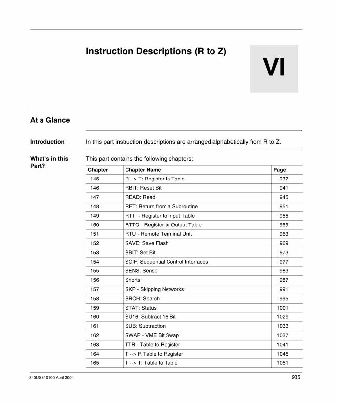
840USE10100 April 2004
VI
Instruction Descriptions (R to Z)At a Glance
Introduction In this part instruction descriptions are arranged alphabetically from R to Z.
What's in this Part?
This part contains the following chapters:
Chapter Chapter Name Page
145 R --> T: Register to Table 937
146 RBIT: Reset Bit 941
147 READ: Read 945
148 RET: Return from a Subroutine 951
149 RTTI - Register to Input Table 955
150 RTTO - Register to Output Table 959
151 RTU - Remote Terminal Unit 963
152 SAVE: Save Flash 969
153 SBIT: Set Bit 973
154 SCIF: Sequential Control Interfaces 977
155 SENS: Sense 983
156 Shorts 987
157 SKP - Skipping Networks 991
158 SRCH: Search 995
159 STAT: Status 1001
160 SU16: Subtract 16 Bit 1029
161 SUB: Subtraction 1033
162 SWAP - VME Bit Swap 1037
163 TTR - Table to Register 1041
164 T --> R Table to Register 1045
165 T --> T: Table to Table 1051
935

Instruction Descriptions (R to Z)
166 T.01 Timer: One Hundredth Second Timer 1057
167 T0.1 Timer: One Tenth Second Timer 1061
168 T1.0 Timer: One Second Timer 1065
169 T1MS Timer: One Millisecond Timer 1069
170 TBLK: Table to Block 1073
171 TEST: Test of 2 Values 1079
172 UCTR: Up Counter 1083
173 VMER - VME Read 1087
174 VMEW - VME Write 1091
175 WRIT: Write 1097
176 XMIT - Transmit 1103
177 XMIT Communication Block 1111
178 XMIT Port Status Block 1123
179 XMIT Conversion Block 1131
180 XMRD: Extended Memory Read 1139
181 XMWT: Extended Memory Write 1145
182 XOR: Exclusive OR 1151
Chapter Chapter Name Page
936 840USE10100 April 2004

840USE10100 April 2004
145
R --> T: Register to TableAt a Glance
Introduction This chapter describes the instruction R → T.
What's in this Chapter?
This chapter contains the following topics:
Topic Page
Short Description 938
Representation: R → T - Register to Table Move 939
Parameter Description 940
937
R --> T: Register to Table
Short Description
Function Description
The R→T instruction copies the bit pattern of a register or of a string of contiguous discretes stored in a word into a specific register located in a table. It can accommodate the transfer of one register/word per scan.
938 840USE10100 April 2004

R --> T: Register to Table
Representation: R → T - Register to Table Move
Symbol Representation of the instruction
Parameter Description
CONTROL INPUT /INCREASE POINTER
PREVENTS POINTERFROM INCREASING
RESET POINTER
ACTIVE
POINTER = TABLE LENGTH
source
destination pointer
R Æ T
table lengthLength:Max. 255 16-bit PLCMax. 999 24-bit PLC
Parameters State RAM Reference
Data Type Meaning
Top input 0x, 1x None ON = copies source data and increments the pointer value
Middle input 0x, 1x None ON = freezes the pointer value
Bottom input 0x, 1x None ON = resets the pointer value to zero
source(top node)
0x, 1x, 3x, 4x
INT, UINT, WORD
Source data to be copied in the current scan
destination pointer(middle node)
4x INT, UINT Destination table where source data will be copied in the scan
table length(bottom node)
INT, UINT Number of registers in the destination table, range: 1 ... 999Length:Max. 255 16-bit PLCMax. 999 24-bit PLC
Top output 0x None Echoes the state of the top input
Middle output 0x None ON = pointer value = table length (instruction cannot increment any further)
840USE10100 April 2004 939

R --> T: Register to Table
Parameter Description
Top Input The input to the top node initiates the DX move operation.
Middle Input When the middle input goes ON, the current value stored in the destination pointer register is frozen while the DX operation continues. This causes new data being copied to the destination to overwrite the data copied on the previous scan.
Bottom Input When the bottom input goes ON, the value in the destination pointer register is reset to zero. This causes the next DX move operation to copy source data into the first register in the destination table.
Source Data (Top Node)
When using register types 0x or 1x:� First 0x reference in a string of 16 contiguous coils or discrete outputs� First 1x reference in a string of 16 discrete inputs
Destination Pointer (Middle Node)
The 4x register entered in the middle node is a pointer to the destination table where source data will be copied in the scan. The first register in the destination table is the next contiguous 4x register following the pointer, i.e. if the pointer register is 400027, then the destination table begins at register 400028.
The value posted in the pointer register indicates the register in the destination table where the source data will be copied. A value of zero indicates that the source data will be copied to the first register in the destination table; a value of 1 indicates that the source data be copied to the second register in the destination table; etc.
Outputs R→T can produce two possible outputs, from the top and middle nodes. The state of the output from the top node echoes the state of the top input. The output from the middle node goes ON when the value in the destination pointer register equals the specified table length. At this point, the instruction cannot increment any further.
Note: The value posted in the destination pointer register cannot be larger than the table length integer specified in this node.
940 840USE10100 April 2004

840USE10100 April 2004
146
RBIT: Reset BitAt a Glance
Introduction This chapter describes the instruction RBIT.
What's in this Chapter?
This chapter contains the following topics:
Topic Page
Short Description 942
Representation: RBIT - Reset Bit 943
941

RBIT: Reset Bit
Short Description
Function Description
The reset bit (RBIT) instruction lets you clear a latched-ON bit by powering the top input. The bit remains cleared after power is removed from the input. This instruction is designed to clear a bit set by the SBIT instruction.
Note: The RBIT instruction does not follow the same rules of network placement as 0x-referenced coils do. An RBIT instruction cannot be placed in column 11 of a network and it can be placed to the left of other logic nodes on the same rungs of the ladder.
942 840USE10100 April 2004

RBIT: Reset Bit
Representation: RBIT - Reset Bit
Symbol Representation of the instruction
Parameter Description
CONTROL INPUT ACTIVE
Bit number to reset(1 - 16)
register #
RBIT
bit #(1 ... 16)
Parameters State RAM Reference
Data Type Meaning
Top input 0x, 1x None ON = clears the specified bit to 0. The bit remains cleared after power is removed from the input
register #(top node)
4x WORD Holding register whose bit pattern is being controlled
bit #(bottom node)
INT, UINT Indicates which one of the 16 bits is being cleared
Top output 0x None ON = the specified bit has been cleared to 0
840USE10100 April 2004 943

RBIT: Reset Bit
944 840USE10100 April 2004

840USE10100 April 2004
147
READ: ReadAt a Glance
Introduction This chapter describes the instruction READ.
What's in this Chapter?
This chapter contains the following topics:
Topic Page
Short Description 946
Representation: READ - Read ASCII Port 947
Parameter Description 948
945

READ: Read
Short Description
Function Description
The READ instruction provides the ability to read data from an ASCII input device (keyboard, bar code reader, etc.) into the PLC’s memory via its RIO network. The connection to the ASCII device is made at an RIO interface.
In the process of handling the messaging operation, READ performs the following functions:� Verifies the lengths of variable data fields� Verifies the correctness of the ASCII communication parameters, e.g. the port
number, the message number� Performs error detection and recording� Reports RIO interface status
READ requires two tables of registers: a destination table where retrieved variable data (the message) is stored, and a control block where comm port and message parameters are identified.
Further information about formatting messages you will find in Formatting Messages for ASCII READ/WRIT Operations, p. 91.
946 840USE10100 April 2004
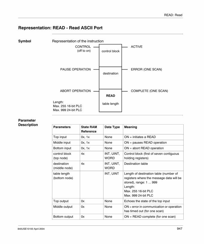
READ: Read
Representation: READ - Read ASCII Port
Symbol Representation of the instruction
Parameter Description
CONTROL(off to on)
PAUSE OPERATION
ABORT OPERATION
ACTIVE
ERROR (ONE SCAN)
COMPLETE (ONE SCAN)
control block
destination
READ
table lengthLength:Max. 255 16-bit PLCMax. 999 24-bit PLC
Parameters State RAM Reference
Data Type Meaning
Top input 0x, 1x None ON = initiates a READ
Middle input 0x, 1x None ON = pauses READ operation
Bottom input 0x, 1x None ON = abort READ operation
control block(top node)
4x INT, UINT, WORD
Control block (first of seven contiguous holding registers)
destination(middle node)
4x INT, UINT, WORD
Destination table
table length(bottom node)
INT, UINT Length of destination table (number of registers where the message data will be stored), range: 1 ... 999Length:Max. 255 16-bit PLCMax. 999 24-bit PLC
Top output 0x None Echoes the state of the top input
Middle output 0x None ON = error in communication or operation has timed out (for one scan)
Bottom output 0x None ON = READ complete (for one scan)
840USE10100 April 2004 947

READ: Read
Parameter Description
Control Block (Top Node)
The 4x register entered in the top node is the first of seven contiguous holding register in the control block.
Register Definition
Displayed Port number and error code
First implied Message number
Second implied Number of registers required to satisfy format
Third implied Count of the number of registers transmitted thus far
Fourth implied Status of the solve
Fifth implied Reserved
Sixth implied Checksum of registers 0 ... 5
948 840USE10100 April 2004

READ: Read
Port Number and Error Code
PLC Error Code
Bit Function
1 ... 4 PLC error code
5 Not used
6 Input from the ASCII device not compatible with format
7 Input buffer overrun, data received too quickly at RIOP
8 USART error, bad byte received at RIOP
9 ASCII device off-line, check cabling
10 Illegal format, not received properly by RIOP
11 ASCII message terminated early (in keyboard mode
12 ... 16 Comm port # (1 ... 32)
Bit Meaning
1 2 3 4
0 0 0 1 Error in the input to RIOP from ASCII device
0 0 1 0 Exception response from RIOP, bad data
0 0 1 1 Sequenced number from RIOP differs from expected value
0 1 0 0 User register checksum error, often caused by altering READ registers while the block is active
0 1 0 1 Invalid port or message number detected
0 1 1 0 User-initiated abort, bottom input energized
0 1 1 1 No response from drop, communication error
1 0 0 0 Node aborted because of SKP instruction
1 0 0 1 Message area scrambled, reload memory
1 0 1 0 Port not configured in the I/O map
1 0 1 2 Illegal ASCII request
1 1 0 0 Unknown response from ASCII port
1 1 0 1 Illegal ASCII element detected in user logic
1 1 1 1 RIOP in the PLC is down
1 2 3 4 5 6 7 8 9 10 11 12 13 14 15 16
840USE10100 April 2004 949

READ: Read
Destination (Middle Node)
The middle node contains the first 4x register in a destination table. Variable data in a READ message are written into this table. The length of the table is defined in the bottom node.
Consider this READ message:
Note: An ASCII READ message may contain the embedded text, placed inside quotation marks, as well as the variable data in the format statement, i.e., the ASCII message.The 10-character ASCII field AAAAAAAAAA is the variable data field; variable data must be entered via an ASCII input device.
please enter password: AAAAAAAAAA
(Embedded Text) (Variable Data)
950 840USE10100 April 2004

840USE10100 April 2004
148
RET: Return from a SubroutineAt a Glance
Introduction This chapter describes the instruction RET.
What's in this Chapter?
This chapter contains the following topics:
Topic Page
Short Description 952
Representation: RET - Return to Scheduled Logic 953
951

RET: Return from a Subroutine
Short Description
Function Description
The RET instruction may be used to conditionally return the logic scan to the node immediately following the most recently executed JSR block. This instruction can be implemented only from within the subroutine segment, the (unscheduled) last segment in the user logic program.
An example to the subroutine handling you will find in Subroutine Handling, p. 107.
Note: If a subroutine does not contain a RET block, either a LAB block or the end-of-logic (whichever comes first) serves as the default return from the subroutine.
952 840USE10100 April 2004

RET: Return from a Subroutine
Representation: RET - Return to Scheduled Logic
Symbol Representation of the instruction
Parameter Description
Description of the instruction’s parameters
RETURN TO PREVIOUSLOGIC
ERRORRET
00001
Parameters State RAM Reference
Data Type Meaning
Top input 0x, 1x None ON = return to previous logicON returns the logic scan to the node immediately following the most recently executed JSR instruction or to the point where the interrupt occurred in the logic scan.
00001 INT, UINT Constant value, can not be changed
Top output 0x None ON = error in the specified subroutine
840USE10100 April 2004 953

RET: Return from a Subroutine
954 840USE10100 April 2004

840USE10100 April 2004
149
RTTI - Register to Input TableAt A Glance
Introduction This chapter describes the instruction RTTI.
What's in this Chapter?
This chapter contains the following topics:
Topic Page
Short Description: RTTI - Register to Input Table 956
Representation: RTTI - Register to Input Table 957
955

RTTI - Register to Input Table
Short Description: RTTI - Register to Input Table
Function Description
The Register to Input Table block is one of four 484-replacement instructions. It copies the contents of an input register or a holding register to another input or holding register. This destination register is pointed to by the input register implied by the constant in the bottom node. Only one such operation can be accommodated by the system in each scan.
956 840USE10100 April 2004

RTTI - Register to Input Table
Representation: RTTI - Register to Input Table
Symbol Representation of the instruction
Parameter Description
Description of the instruction’s parameters
CONTROL INPUT ACTIVE
ERROR
source
RTTI
destinationoffset pointer
Parameters State RAM Reference
Data Type Meaning
Top input 0x, 1x None Control source
source(top node)
3x, 4x INT, UINT The source node (top node) contains the source register address. The data located in the source register address will be copied to the destination address, which is determined by the destination offset pointer.
pointer(bottom node)
(1 ... 254)(801 ... 832)
INT, UINT The pointer is a 3xxxx implied by a constant (i.e. 00018 -> 30018) whose contents indicate the destination. A value of 1 to 254 indicates a holding register (40001 - 40254) and a value of 801 to 832 indicates an input register (30001 - 30032). If the value is outside this range, the operation is not performed and the ERROR rail is powered. Note the pointer's value is NOT automatically increased.
Top output 0x None Echoes the value of the top input
Bottom output 0x None ON = errorPointer value out of range
840USE10100 April 2004 957

RTTI - Register to Input Table
958 840USE10100 April 2004
840USE10100 April 2004
150
RTTO - Register to Output TableAt A Glance
Introduction This chapter describes the instruction RTTO.
What's in this Chapter?
This chapter contains the following topics:
Topic Page
Short Description: RTTO - Register to Output Table 960
Representation: RTTO - Register to Output Table 961
959

RTTO - Register to Output Table
Short Description: RTTO - Register to Output Table
Function Description
The Register to Output Table block is one of four 484-replacement instructions. It copies the contents of an input register or a holding register to another input or holding register. The holding register implied by the constant in the bottom node points to this destination register. Only one such operation can be accommodated by the system in each scan.
960 840USE10100 April 2004

RTTO - Register to Output Table
Representation: RTTO - Register to Output Table
Symbol Representation of the instruction
Parameter Description
Description of the instruction’s parameters
CONTROL INPUT COPY
ERROR
source
RTTO
destinationoffset pointer
Parameters State RAM Reference
Data Type Meaning
Top input 0x, 1x None Control source
source(top node)
3x, 4x INT, UINT The source node (top node) contains the source register address. The data located in the source register address will be copied to the destination address, which is determined by the destination offset pointer.
pointer(bottom node)
(1 ... 254)(801 ... 824)
INT, UINT The pointer is a 4xxxx implied by a constant (i.e. 00018 -> 40018) whose contents indicate the destination. A value of 1 to 254 indicates a holding register (40001 - 40254) and a value of 801 to 832 indicates an input register (30001 - 30032). If the value is outside this range, the operation is not performed and the ERROR rail is powered. Note that the pointer's value is NOT automatically increased.
Top output 0x None Echoes the value of the top input
Bottom output 0x None ON = errorPointer value out of range
840USE10100 April 2004 961

RTTO - Register to Output Table
962 840USE10100 April 2004

840USE10100 April 2004
151
RTU - Remote Terminal UnitAt A Glance
Introduction This chapter describes the instruction RTU.
What's in this Chapter?
This chapter contains the following topics:
Topic Page
Short Description: RTU - Remote Terminal Unit 964
Representation: RTU - Remote Terminal Unit 965
963
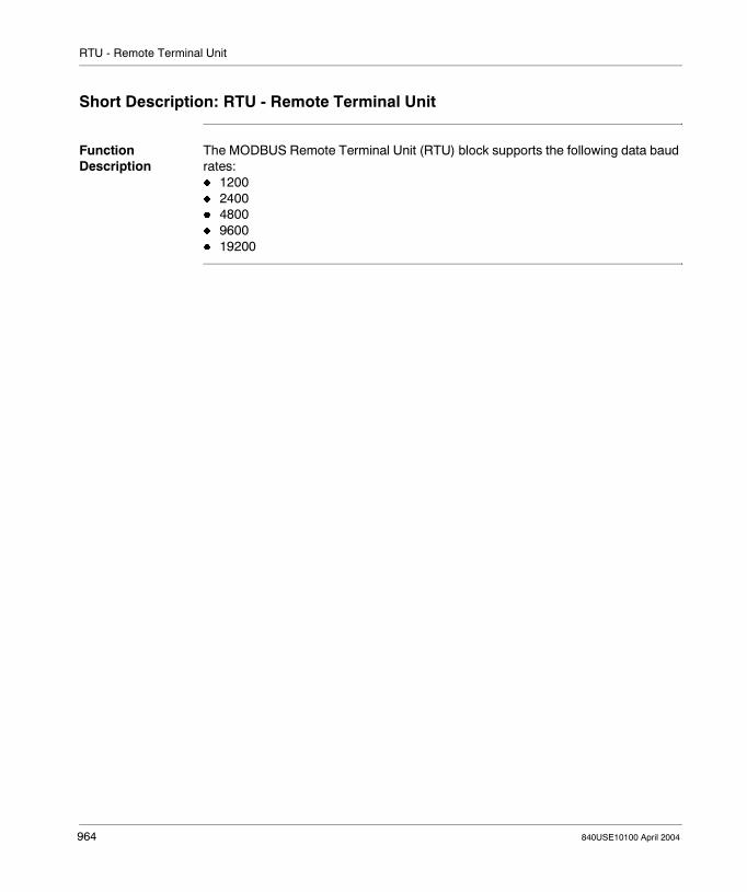
RTU - Remote Terminal Unit
Short Description: RTU - Remote Terminal Unit
Function Description
The MODBUS Remote Terminal Unit (RTU) block supports the following data baud rates:� 1200� 2400� 4800� 9600� 19200
964 840USE10100 April 2004

RTU - Remote Terminal Unit
Representation: RTU - Remote Terminal Unit
Parameter Description
Description of the instructions parameters
Register Entries for Baud Rates
The MODBUS Remote Terminal Unit (RTU) block supports the following data baud rates:� 1200� 2400� 4800� 9600� 19200Below are the register entries for the supported data rates. To configure a data rate, type the appropriate decimal number (for example 1200) in the data baud rate register.
Register Function
4x RTU revision number (read-only)
4x + 1 Fault status field (read-only)
4x + 2 Field not used
4x + 3 Set the Data Baud Rate registerFor expanded and detailed information about the register entries for baud rates please see the section below: Register Entries for Baud Rates.
4x + 4 Set the Data Bits registerFor expanded and detailed information about the register entries for data bits please see the section below: Register Entries for Data Bits
4x + 5 Parity register
4x + 6 Stop bit register
4x + 7 Field not used
4x + 8 Set the Command Word registerFor expanded and detailed information about the register entries for command words please see the section below: Register Entries for Command Words
Register Entry Baud Rate
1200 1200
2400 2400
4800 4800
9600 9600
19200 19200
840USE10100 April 2004 965

RTU - Remote Terminal Unit
Register Entries for Data Bits
The RTU block supports data bits 7 and 8. Below are the possible register entries for the data bits field:
Modbus messages can be sent in Modbus RTU format or Modbus ASCII format.� If messages are sent in Modbus ASCII format, type 7 in the field.� If messages are sent in Modbus RTU format, type 8.If you're sending ASCII character messages, this register can be set to 7 or 8 data bits.
Register Entries for Command Words
The RTU block interprets each bit of the command word as a function to implement or perform. Below are the bit definitions for the command word register entries.
Register Entry Data Bit Field
7 7
8 8
Register Entry Definitions
1 (msb) Not used
2 Enable RTS/CTS control
3 Not used
4 Not used
5 Not used
6 Not used
7 Enable ASCII string messaging
8 Enable Modbus messaging
9 Not used
10 Not used
11 Not used
12 Not used
13 Not used
14 Hang up modem
15 Dial modem
16 (lsb) Initialize modem
966 840USE10100 April 2004

RTU - Remote Terminal Unit
The following items provide expanded and detailed information about Bits 2, 7, and 8.
� Bit 2 – Enable request-to-send/clear-to-send (RTS/CTS) controlThis bit should be set (or true) when a DCE that is connected to the PLC requires hardware handshaking using RTS/CTS control.This bit can be used in conjunction with the values contained in the (4xxxx ¸ 13) start-of-transmission delay register and the (4xxxx + 13) end-of-transmission delay register. Start-of-transmission delay keeps RTS asserted for 0-9999 ms before the RTU block sends a message from the PLC port. After the RTU block sends a message, end-of-transmission delay keeps RTS asserted for 0-9999 ms. When end-of-transmission delay has expired, the RTU block de-asserts RTS.
� Bit 7 – Enable ASCII string messagingThis bit should be set (or true) to send ASCII string messages form the PLC communication Port #1. The RTU block can send an ASCII string of up to 512 characters in length. Each ASCII message must be programmed into contiguous 4x registers of the PLC. Two characters per register are allowed.Note: This ASCII message string should NOT be confused with a Modbus message sent in ASCII format.
� Bit 8 – Enable Modbus messagingThis bit should be set (or true) to send Modbus messages from the PLC communication Port #1.Modbus messages can be sent in RTU or ASCII formats.� If sending Modbus messages in RTU format, set the data bits in the (4xxxx +
4) data bits register to 8. � If sending Modbus message in ASCII format, set the data bits in the (4xxxx +
4) data bits register to 7.
840USE10100 April 2004 967

RTU - Remote Terminal Unit
968 840USE10100 April 2004

840USE10100 April 2004
152
SAVE: Save FlashAt a Glance
Introduction This chapter describes the instruction SAVE.
What's in this Chapter?
This chapter contains the following topics:
Topic Page
Short Description 970
Representation: SAVE - Save 971
Parameter Description 972
969

SAVE: Save Flash
Short Description
Function Description
The SAVE instruction saves a block of 4x registers to state RAM where they are protected from unauthorized modification.
Note: This instruction is available with the PLC family TSX Compact, with Quantum CPUs 434 12/ 534 14 and Momentum CPUs CCC 960 x0/ 980 x0.
970 840USE10100 April 2004

SAVE: Save Flash
Representation: SAVE - Save
Symbol Representation of the instruction
Parameter Description
Description of the instruction’s parameters
CONTROL INPUT ACTIVE
ERRORSAVE not allowed
register
1, 2, 3, 4
SAVE
length
Parameters State RAM Reference
Data Type Meaning
Top input 0x, 1x None Start SAVE operation: it should remain ON until the operation has completed successfully or an error has occurred.
register(top node)
4x INT, UINT, WORD
First of max. 512 contiguous 4x registers to be saved to state RAM
1, 2, 3, 4 (See 1, 2, 3, 4 (Middle Node), p. 972)(middle node)
INT Integer value, which defines the specific buffer where the block of data is to be saved
length(bottom node)
INT Number of words to be saved, range: 1 ... 512
Top output 0x None ON = SAVE is active
Middle output (See Middle Output, p. 972)
0x None ON = SAVE is not allowed
840USE10100 April 2004 971

SAVE: Save Flash
Parameter Description
1, 2, 3, 4 (Middle Node)
The middle node defines the specific buffer, within state RAM, where the block of data is to be saved. Four 512 word buffers are allowed. Each buffer is defined by placing its corresponding value in the middle node, that is, the value 1 represents the first buffer, value 2 represents the second buffer and so on. The legal values are 1, 2, 3, and 4. When the PLC is started all four buffers are zeroed. Therefore, you may not save data to the same buffer without first loading it with the instruction LOAD (See LOAD: Load Flash, p. 665). When this is attempted the middle output goes ON. In other words, once a buffer is used, it may not be used again until the data has been removed.
Middle Output The output from the middle node goes ON when previously saved data has not been accessed using the LOAD (See LOAD: Load Flash, p. 665) instruction. This prevents inadvertent overwriting of data in the SAVE buffer.
972 840USE10100 April 2004

840USE10100 April 2004
153
SBIT: Set BitAt a Glance
Introduction This chapter describes the instruction SBIT.
What's in this Chapter?
This chapter contains the following topics:
Topic Page
Short Description 974
Representation: SBIT - Set Bit 975
973
SBIT: Set Bit
Short Description
Function Description
The set bit (SBIT) instruction lets you set the state of the specified bit to ON (1) by powering the top input.
Note: The SBIT instruction does not follow the same rules of network placement as 0x-referenced coils do. An SBIT instruction cannot be placed in column 11 of a network and it can be placed to the left of other logic nodes on the same rungs of the ladder.
974 840USE10100 April 2004

SBIT: Set Bit
Representation: SBIT - Set Bit
Symbol Representation of the instruction
Parameter Description
Description of the instruction’s parameters
ON SETS BIT TO 1 ACTIVEregister #
SBIT
bit #(1 ... 16)
Parameters State RAM Reference
Data Type Meaning
Top input 0x, 1x None ON = sets the specified bit to 1. The bit remains set after power is removed from the input
register #(top node)
4x WORD Holding register whose bit pattern is being controlled
bit #(bottom node)
INT, UINT Indicates which one of the 16 bits is being set
Top output 0x None Goes ON, when the specified bit is set and remains ON until it is cleared (via the RBIT (See RBIT: Reset Bit, p. 941) instruction)
840USE10100 April 2004 975

SBIT: Set Bit
976 840USE10100 April 2004

840USE10100 April 2004
154
SCIF: Sequential Control InterfacesAt a Glance
Introduction This chapter describes the instruction SCIF.
What's in this Chapter?
This chapter contains the following topics:
Topic Page
Short Description 978
Representation: SCIF - Sequential Control Interface 979
Parameter Description 981
977

SCIF: Sequential Control Interfaces
Short Description
Function Description
The SCIF instruction performs either a drum sequencing operation or an input comparison (ICMP) using the data defined in the step data table.
The choice of operation is made by defining the value in the first register of the step data table (See Step Data Table (Middle Node), p. 981):� 0 = drum mode:
The instruction controls outputs in the drum sequencing application.� 1 = ICMP mode:
The instruction reads inputs to ensure that limit switches, proximity switches, pushbuttons, etc. are properly positioned to allow drum outputs to be fired.
978 840USE10100 April 2004

SCIF: Sequential Control Interfaces
Representation: SCIF - Sequential Control Interface
Symbol Representation of the instruction
CONTROL INPUT ACTIVEstep pointer
step data table
SCIF
length(1 ... 255)
Length: 1 - 255
OPERATION SPECIFIC OPERATION SPECIFIC
RESET STEP POINTER ERROR
840USE10100 April 2004 979

SCIF: Sequential Control Interfaces
Parameter Description
Description of the instruction’s parameters
Parameters State RAM Reference
Data Type Meaning
Top input 0x, 1x None ON = initiates specified sequence control operation
Middle input 0x, 1x None Drum mode: step pointer increments to the next stepICMP mode: compare status is shown at the middle output
Bottom input 0x, 1x None Drum mode: ON = reset step pointer to 0ICMP mode: not used
step pointer(top node)
4x INT, UINT Number of the current step in the step data table
step data table (See Step Data Table (Middle Node), p. 981)(middle node)
4x INT, UINT First register in the step data table(For expanded and detailed information please see the section Step Data Table (Middle Node), p. 981.)
length (See Length of Step Data Table (Bottom Node), p. 982)(bottom node)
INT, UINT Number of application-specific registers used in the step data table
Top output 0x None Echoes state of the top input
Middle output 0x None Drum mode goes ON for the last stepNote: When using the middle output, be aware that when integrating with other logic, if the step pointer is zero and the middle input is ON, then the middle output will also be ON. This condition will cause the step pointer to be one step out of sequence.
Bottom output 0x None ON = error is detected
980 840USE10100 April 2004

SCIF: Sequential Control Interfaces
Parameter Description
Step Data Table (Middle Node)
The 4x register entered in the middle node is the first register in the step data table. The first seven registers in the table hold constant and variable data required to solve the instruction:
Register Register Name Description
Displayed subfunction type 0 = drum mode; 1 = ICMP mode (entry of any other value in this register will result in all outputs OFF)
First implied
masked output data(in drum mode)
Loaded by SCIF each time the block is solved; the register contains the contents of the current step data register masked with the output mask register
raw input data(in ICMP mode)
Loaded by the user from a group of sequential inputs to be used by the block in the current step
Second implied
current step data Loaded by SCIF each time the block is solved; the register contains data from the current step (pointed to by the step pointer)
Third implied
output mask(in drum mode)
Loaded by the user before using the block, the contents will not be altered during logic solving; contains a mask to be applied to the data for each sequencer step
input mask(in ICMP mode)
Loaded by the user before using the block, it contains a mask to be ANDed with raw input data for each step, masked bits will not be compared; the masked data are put in the masked input data register
Fourth implied
masked input data(in ICMP mode)
Loaded by SCIF each time the block is solved, it contains the result of the ANDed input mask and raw input data
not used in drum mode
Fifth implied
compare status(in ICMP mode)
Loaded by SCIF each time the block is solved, it contains the result of an XOR of the masked input data and the current step data; unmasked inputs that are not in the correct logical state cause the associated register bit to go to 1, non-zero bits cause a miscompare and turn ON the middle output from the SCIF block
not used in drum mode
Sixth implied
start of data table First of K registers in the table containing the user-specified control dataNote: This and the rest of the registers represent application-specific step data in the process being controlled.
840USE10100 April 2004 981

SCIF: Sequential Control Interfaces
Length of Step Data Table (Bottom Node)
The integer value entered in the bottom node is the length, i.e. the number of application-specific registers, used in the step data table. The length can range from 1 ... 255.
The total number of registers required in the step data table is the length + 7. The length must be ≥ the value placed in the steps used register in the middle node.
982 840USE10100 April 2004

840USE10100 April 2004
155
SENS: SenseAt a Glance
Introduction This chapter describes the instruction SENS.
What's in this Chapter?
This chapter contains the following topics:
Topic Page
Short Description 984
Representation: SENS - Logical Bit-Sense 985
Parameter Description 986
983

SENS: Sense
Short Description
Function Description
The SENS instruction examines and reports the sense (1 or 0) of a specific bit location in a data matrix. One bit location is sensed per scan.
984 840USE10100 April 2004

SENS: Sense
Representation: SENS - Logical Bit-Sense
Symbol Representation of the instruction
Parameter Description
Description of the instruction’s parameters
CONTROL INPUT
INCREASE POINTER
RESET POINTER
ACTIVE
SENSE BIT (ON/OFF)
ERROROperation not performedPointer > Matrix size
bit location
data matrix
SENS
lengthMatrix length (max)255 Registers (4080 bits 16-bit PLC)600 Registers (9600 bits 24-bit PLC)
Pointer: (999 16-bit PLC)(max) (9600 24-bit PLC)
Parameters State RAM Reference
Data Type
Meaning
Top input 0x, 1x None ON = senses the bit location
Middle input 0x, 1x None Increment bit location by one on next scan
Bottom input 0x, 1x None Reset bit location to 1
bit location (see p. 986)(top node)
3x, 4x WORD Specific bit location to be sensed in the data matrix, entered explicitly as an integer or stored in a register; range: 1 ... 9600Pointer: ( 999 16-bit PLC)(max) (9900 24-bit PLC)
data matrix(middle node)
0x, 4x BOOL, WORD
First word or register in the data matrix
length (See p. 986)(bottom node)
INT, UINT
Matrix length max255 Registers (4080 bits 16-bit PLC)600 Registers (9600 bits 24-bit PLC)
Top output 0x None Echoes state of the top input
Middle output 0x None ON = bit sense is 1OFF = bit sense is 0
Bottom output 0x None ON = error: bit location > matrix length
840USE10100 April 2004 985

SENS: Sense
Parameter Description
Bit Location (Top Node)
Matrix Length (Bottom Node)
The integer value entered in the bottom node specifies a matrix length, i.e, the number of 16-bit words or registers in the data matrix. The length can range from 1 ... 600 in a 24-bit CPU, e.g, a matrix length of 200 indicates 3200 bit locations.
Note: If the bit location is entered as an integer or in a 3x register, the instruction will ignore the state of the middle and bottom inputs.
986 840USE10100 April 2004

840USE10100 April 2004
156
ShortsAt A Glance
Introduction This chapter describes the instruction element Shorts.
What's in this Chapter?
This chapter contains the following topics:
Topic Page
Short Description: Shorts 988
Representation: Shorts 989
987

Shorts
Short Description: Shorts
Function Description
Shorts are simply straight-line connections between contacts and/or instructions in a ladder logic network. Vertical (|) and horizontal (—) shorts are used to make connections between rows and columns of logic. To cancel a vertical short, use a vertical open.
988 840USE10100 April 2004

Shorts
Representation: Shorts
Vertical Shorts Connects contacts or instructions vertically in a network column, or node inputs and outputs to create either/or conditions. When two contacts are connected by vertical shorts, power is passed when one or both contacts receive power.
Horizontal Shorts
Expands logic horizontally along a rung in a ladder logic network
840USE10100 April 2004 989

Shorts
990 840USE10100 April 2004

840USE10100 April 2004
157
SKP - Skipping NetworksAt A Glance
Introduction This chapter describes the instruction SKP.
What's in this Chapter?
This chapter contains the following topics:
Topic Page
Short Description: SKP - Skipping Networks 992
Representation: SKP - Skipping Networks 993
991

SKP - Skipping Networks
Short Description: SKP - Skipping Networks
Function Description
The SKP instruction is a standard instruction in all PLCs. It should be used with cautionThe SKP instruction is used to reduce the scan time by not solving a portion of the logic. The SKP instruction causes the logic scan to skip specified networks in the program.The SKP function can be used to� Bypass seldom used program sequences� Create subroutinesThe SKP instruction allows you to skip a specified number of networks in a ladder logic program. When it is powered, the SKP operation is performed on every scan. The remainder of the network in which the instruction appears counts as the first of the specified number of networks to be skipped. The CPU continues to skip networks until the total number of networks skipped equals the number specified in the instruction block or until a segment boundary is reached. A SKP operation cannot cross a segment boundary.A SKP instruction can be activated only if you specify in the PLC set-up editor that skips are allowed. SKP is a one-high nodal instruction.
WARNING
Skipped inputs and outputs
SKP is a dangerous instruction that should be used carefully. If inputs and outputs that normally effect control are unintentionally skipped (or not skipped), the result can create hazardous conditions for personnel and application equipment.
Failure to follow this precaution can result in death, serious injury, or equipment damage.
CAUTION
Reading values while changing
Use 3xxxx and 4xxxx registers with caution. The processor can read the value while it's changing.
Failure to follow this precaution can result in injury or equipment damage.
992 840USE10100 April 2004
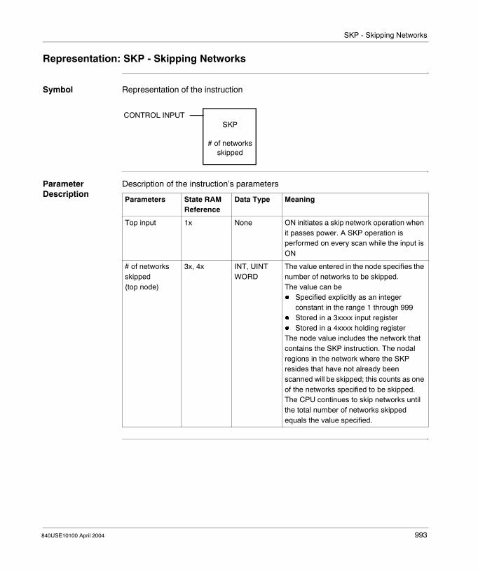
SKP - Skipping Networks
Representation: SKP - Skipping Networks
Symbol Representation of the instruction
Parameter Description
Description of the instruction’s parameters
CONTROL INPUTSKP
# of networks skipped
Parameters State RAM Reference
Data Type Meaning
Top input 1x None ON initiates a skip network operation when it passes power. A SKP operation is performed on every scan while the input is ON
# of networks skipped(top node)
3x, 4x INT, UINT WORD
The value entered in the node specifies the number of networks to be skipped. The value can be� Specified explicitly as an integer
constant in the range 1 through 999� Stored in a 3xxxx input register� Stored in a 4xxxx holding registerThe node value includes the network that contains the SKP instruction. The nodal regions in the network where the SKP resides that have not already been scanned will be skipped; this counts as one of the networks specified to be skipped. The CPU continues to skip networks until the total number of networks skipped equals the value specified.
840USE10100 April 2004 993

SKP - Skipping Networks
994 840USE10100 April 2004

840USE10100 April 2004
158
SRCH: SearchAt a Glance
Introduction This chapter describes the instruction SRCH.
What's in this Chapter?
This chapter contains the following topics:
Topic Page
Short Description 996
Representation: SRCH - Search 997
Parameter Description 999
995

SRCH: Search
Short Description
Function Description
The SRCH instruction searches the registers in a source table for a specific bit pattern.
996 840USE10100 April 2004

SRCH: Search
Representation: SRCH - Search
Symbol Representation of the instruction
Parameter Description
Description of the instruction’s parameters
CONTROL INPUT
START SEARCH ATPOINTER REGISTER
ACTIVE
MATCH FOUND
source table
pointer
SRCH
table lengthLength: 1 - 100 registers
Parameters State RAM Reference
Data Type Meaning
Top input 0x, 1x None ON = initiates search
Middle input 0x, 1x None OFF = search from beginningON = search from last match
source table(top node)
3x, 4x INT, UINT, WORD
Source table to be searched
pointer (See Pointer (Middle Node), p. 999)(middle node)
4x INT, UINT Pointer into the source table
table length(bottom node)
INT, UINT Number of registers in the source table; range: 1 ... 100
Top output 0x None Echoes state of the top input
Middle output 0x None ON = match found
840USE10100 April 2004 997

SRCH: Search
A SRCH Example In the following example, we search a source table that contains five registers (40421 ... 40425) for a specific bit pattern. The pointer register (40430) indicates that the desired bit pattern is stored in register 40431, and we see that the register contains a bit value of 3333.
In each scan where P.T. contact 10001 transitions from OFF to ON, the source table is searched for a bit pattern equivalent to the value 3333. when the math is found, the middle output passes power to coil 00142.If N.O. contact 10002 is OFF when the match is found at register 40423, the SRCH instruction energizes coil 00142 for one scan, then starts the search again in the next scan at the top of the source table (register 40421). If contact 10002 is ON, the SRCH instruction energizes coil 00142 for one scan, then starts the search in register 40424,Because the top input is a P.T. contact, on any scan where power is not applied to the top input the pointer value is cleared. We use a BLKM instruction here to sage the pointer value to register 40500.
40424
40421
40430
00005SRCH
10001
10002
00142
40430
40500
0001BLKM
40421
4042240423
40425= 4444
= 1111
= 2222= 3333
= 5555
40430
40431 = 3333
registercontent
registercontentsource table
pointer
998 840USE10100 April 2004

SRCH: Search
Parameter Description
Pointer (Middle Node)
The 4x register entered in the middle node is the pointer into the source table. It points to the source register that contains the same value as the value stored in the next contiguous register after the pointer, e.g. if the pointer register is 400015, then register 400016 contains a value that the SRCH instruction will attempt to match in source table.
840USE10100 April 2004 999

SRCH: Search
1000 840USE10100 April 2004

840USE10100 April 2004
159
STAT: StatusAt a Glance
Introduction This chapter describes the instruction STAT.
What's in this Chapter?
This chapter contains the following topics:
Topic Page
Short Description 1002
Representation: STAT - Status 1003
Parameter Description 1004
Description of the Status Table 1005
Controller Status Words 1 - 11 for Quantum and Momentum 1009
I/O Module Health Status Words 12 - 20 for Momentum 1014
I/O Module Health Status Words 12 - 171 for Quantum 1016
Communication Status Words 172 - 277 for Quantum 1018
Controller Status Words 1 - 11 for TSX Compact and Atrium 1023
I/O Module Health Status Words 12 - 15 for TSX Compact 1026
Global Health and Communications Retry Status Words 182 ... 184 for TSX Compact 1027
1001

STAT: Status
Short Description
Function Description
The STAT instruction accesses a specified number of words in a status table (See Description of the Status Table, p. 1005) in the PLC’s system memory. Here vital diagnostic information regarding the health of the PLC and its remote I/O drops is posted.
This information includes:� PLC status� Possible error conditions in the I/O modules� Input-to-PLC-to-output communication status
1002 840USE10100 April 2004

STAT: Status
Representation: STAT - Status
Symbol Representation of the instruction
Parameter Description
Description of the instruction’s parameters
CONTROL DESTINATION TOP INPUTdestination
STAT
length
Parameters State RAM Reference
Data Type
Meaning
Top input 0x, 1x None ON = copies specified number of words from the status table
destination (See p. 1004)(top node)
0x, 4x INT, UINT, BOOL, WORD
First position in the destination block
length (See p. 1004)(bottom node)
INT, UINT
number of registers or 16-bit words in the destination blockThe integer value entered in the bottom node specifies a matrix length - i.e., the number of 16-bit words or registers in the data matrix. The length can range from 1 through 255 in a 16-bit CPU and from 1 through 600 in a 24-bit CPU—e.g., a matrix length of 200 indicates 3200 bit locations.Note: If 0xxxx references are used as the destination, they cannot be programmed as coils, only as contacts referencing those coil numbers.(For expanded and detailed information regarding table length and PLCs see the section Length (Bottom Node), p. 1004.)
Top output 0x None ON = operation successful
840USE10100 April 2004 1003
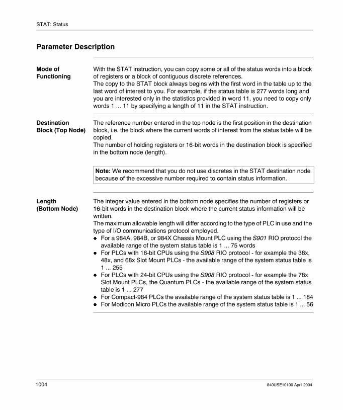
STAT: Status
Parameter Description
Mode of Functioning
With the STAT instruction, you can copy some or all of the status words into a block of registers or a block of contiguous discrete references.The copy to the STAT block always begins with the first word in the table up to the last word of interest to you. For example, if the status table is 277 words long and you are interested only in the statistics provided in word 11, you need to copy only words 1 ... 11 by specifying a length of 11 in the STAT instruction.
Destination Block (Top Node)
The reference number entered in the top node is the first position in the destination block, i.e. the block where the current words of interest from the status table will be copied.The number of holding registers or 16-bit words in the destination block is specified in the bottom node (length).
Length (Bottom Node)
The integer value entered in the bottom node specifies the number of registers or 16-bit words in the destination block where the current status information will be written.The maximum allowable length will differ according to the type of PLC in use and the type of I/O communications protocol employed.� For a 984A, 984B, or 984X Chassis Mount PLC using the S901 RIO protocol the
available range of the system status table is 1 ... 75 words� For PLCs with 16-bit CPUs using the S908 RIO protocol - for example the 38x,
48x, and 68x Slot Mount PLCs - the available range of the system status table is 1 ... 255
� For PLCs with 24-bit CPUs using the S908 RIO protocol - for example the 78x Slot Mount PLCs, the Quantum PLCs - the available range of the system status table is 1 ... 277
� For Compact-984 PLCs the available range of the system status table is 1 ... 184� For Modicon Micro PLCs the available range of the system status table is 1 ... 56
Note: We recommend that you do not use discretes in the STAT destination node because of the excessive number required to contain status information.
1004 840USE10100 April 2004

STAT: Status
Description of the Status Table
General The STAT instruction is used to display the Status of Controller and I/O system for Quantum (See Quantum Overview, p. 1005), Atrium (See TSX Compact and Atrium Overview, p. 1008), TSX Compact (See TSX Compact and Atrium Overview, p. 1008) and Momentum (See Momentum Overview, p. 1007).The first 11 status words are used by Quantum and Momentum in the same way and by TSX Compact and Atrium in the same way. The following have a different meaning for Quantum, TSX Compact and Momentum.
Quantum Overview
The 277 words in the status table are organized in three sections:� Controller Status (words 1 ... 11) (See Controller Status Words 1 - 11 for
Quantum and Momentum, p. 1009)� I/O Module Health (words 12 ... 171) (See I/O Module Health Status Words 12 -
171 for Quantum, p. 1016)� I/O Communications Health (words 172 ... 277) (See Communication Status
Words 172 - 277 for Quantum, p. 1018)Words of the status table:
Decimal Word
Word Content Hex Word
1 Controller Status 01
2 Hot Standby Status 02
3 Controller Status 03
4 RIO Status 04
5 Controller Stop State 06
6 Number of Ladder Logic Segments 06
7 End-of-logic (EOL) Pointer 07
8 RIO Redundancy and Timeout 08
9 ASCII Message Status 09
10 RUN/LOAD/DEBUG Status 0A
11 not used 0B
12 Drop 1, Rack 1 0C
13 Drop 1, Rack 2 0D
. . . . . . . . . . . .
16 Drop 1, Rack 5 0F
17 Drop 2, Rack 1 10
18 Drop 2, Rack 2 11
. . . . . . . . . . . .
840USE10100 April 2004 1005
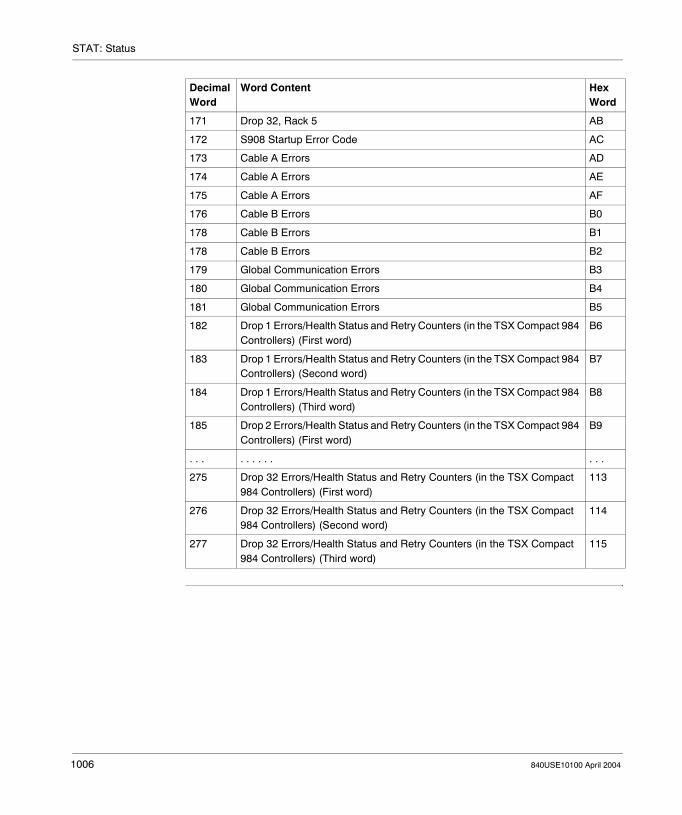
STAT: Status
171 Drop 32, Rack 5 AB
172 S908 Startup Error Code AC
173 Cable A Errors AD
174 Cable A Errors AE
175 Cable A Errors AF
176 Cable B Errors B0
178 Cable B Errors B1
178 Cable B Errors B2
179 Global Communication Errors B3
180 Global Communication Errors B4
181 Global Communication Errors B5
182 Drop 1 Errors/Health Status and Retry Counters (in the TSX Compact 984 Controllers) (First word)
B6
183 Drop 1 Errors/Health Status and Retry Counters (in the TSX Compact 984 Controllers) (Second word)
B7
184 Drop 1 Errors/Health Status and Retry Counters (in the TSX Compact 984 Controllers) (Third word)
B8
185 Drop 2 Errors/Health Status and Retry Counters (in the TSX Compact 984 Controllers) (First word)
B9
. . . . . . . . . . . .
275 Drop 32 Errors/Health Status and Retry Counters (in the TSX Compact 984 Controllers) (First word)
113
276 Drop 32 Errors/Health Status and Retry Counters (in the TSX Compact 984 Controllers) (Second word)
114
277 Drop 32 Errors/Health Status and Retry Counters (in the TSX Compact 984 Controllers) (Third word)
115
Decimal Word
Word Content Hex Word
1006 840USE10100 April 2004

STAT: Status
Momentum Overview
The 20 words in the status table are organized in two sections:� Controller Status (words 1 ... 11) (See Controller Status Words 1 - 11 for
Quantum and Momentum, p. 1009)� I/O Module Health (words 12 ... 20) (See I/O Module Health Status Words 12 - 20
for Momentum, p. 1014)Words of the status table:
Decimal Word Word Content Hex Word
1 Controller Status 01
2 Hot Standby Status 02
3 Controller Status 03
4 RIO Status 04
5 Controller Stop State 06
6 Number of Ladder Logic Segments 06
7 End-of-logic (EOL) Pointer 07
8 RIO Redundancy and Timeout 08
9 ASCII Message Status 09
10 RUN/LOAD/DEBUG Status 0A
11 not used 0B
12 Local Momentum I/O Module Health 0C
13 I/O Bus Module Health 0D
14 I/O Bus Module Health 0E
15 I/O Bus Module Health 0F
16 I/O Bus Module Health 10
17 I/O Bus Module Health 11
18 I/O Bus Module Health 12
19 I/O Bus Module Health 13
20 I/O Bus Module Health 14
840USE10100 April 2004 1007
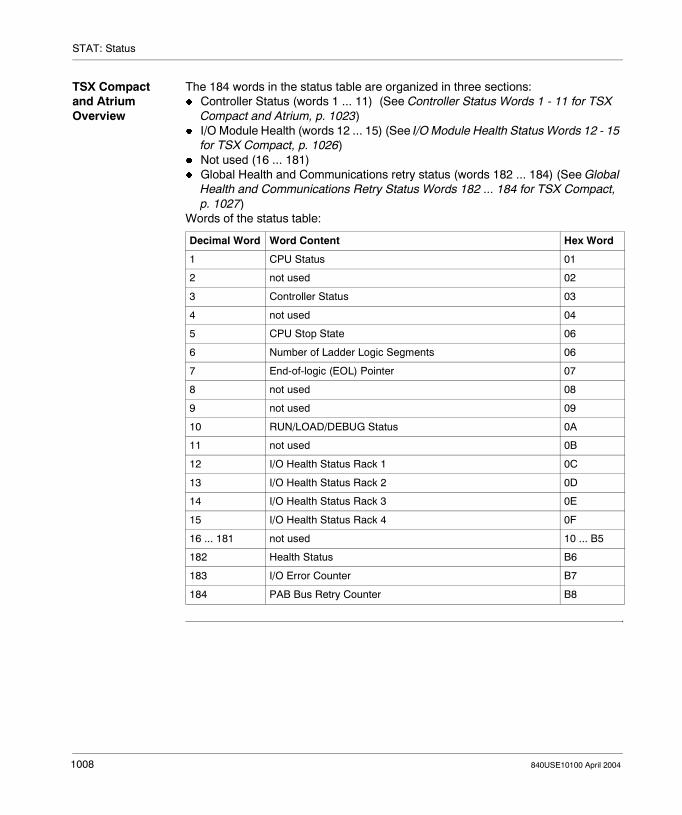
STAT: Status
TSX Compact and Atrium Overview
The 184 words in the status table are organized in three sections:� Controller Status (words 1 ... 11) (See Controller Status Words 1 - 11 for TSX
Compact and Atrium, p. 1023)� I/O Module Health (words 12 ... 15) (See I/O Module Health Status Words 12 - 15
for TSX Compact, p. 1026)� Not used (16 ... 181)� Global Health and Communications retry status (words 182 ... 184) (See Global
Health and Communications Retry Status Words 182 ... 184 for TSX Compact, p. 1027)
Words of the status table:
Decimal Word Word Content Hex Word
1 CPU Status 01
2 not used 02
3 Controller Status 03
4 not used 04
5 CPU Stop State 06
6 Number of Ladder Logic Segments 06
7 End-of-logic (EOL) Pointer 07
8 not used 08
9 not used 09
10 RUN/LOAD/DEBUG Status 0A
11 not used 0B
12 I/O Health Status Rack 1 0C
13 I/O Health Status Rack 2 0D
14 I/O Health Status Rack 3 0E
15 I/O Health Status Rack 4 0F
16 ... 181 not used 10 ... B5
182 Health Status B6
183 I/O Error Counter B7
184 PAB Bus Retry Counter B8
1008 840USE10100 April 2004

STAT: Status
Controller Status Words 1 - 11 for Quantum and Momentum
Controller Status (Word 1)
Word 1 displays the following aspects of the PLC status:
Hot Standby Status (Word 2)
Word 2 displays the Hot Standby status for 984 PLCs that use S911/R911 Hot Standby Modules:
Bit Function
1 - 5 Not used
6 1 = enable constant sweep
7 1 = enable single sweep delay
8 1 = 16 bit user logic0 = 24 bit user logic
9 1 = AC power on
10 1 = RUN light OFF
11 1 = memory protect OFF
12 1 = battery failed
13 - 16 Not used
1 2 3 4 5 6 7 8 9 10 11 12 13 14 15 16
Bit Function
1 1 = S911/R911 present and healthy
2 - 10 Not used
11 0 = controller toggle set to A1 = controller toggle set to B
12 0 = controllers have matching logic1 = controllers do not have matching logic
13, 14 Remote system state:0 1 = Off line (1 dec)1 0 = primary (2 dec)1 1 = standby (3 dec)
15, 16 Local system state:0 1 = Off line (1 dec)1 0 = primary (2 dec)1 1 = standby (3 dec)
1 2 3 4 5 6 7 8 9 10 11 12 13 14 15 16
840USE10100 April 2004 1009

STAT: Status
Controller Status (Word 3)
Word 3 displays more aspects of the controller status:
RIO Status (Word 4)
Word 4 is used for IOP information:
Bit Function
1 1 = first scan
2 1 = start command pending
3 1 = constant sweep time exceeded
4 1 = Existing DIM AWARENESS
5 - 12 Not used
13 - 16 Single sweeps
1 2 3 4 5 6 7 8 9 10 11 12 13 14 15 16
Bit Function
1 1 = IOP bad
2 1 = IOP time out
3 1 = IOP loop back
4 1 = IOP memory failure
5 - 12 Not used
13 - 16 00 = IO did not respond01 = no response02 = failed loopback
1 2 3 4 5 6 7 8 9 10 11 12 13 14 15 16
1010 840USE10100 April 2004

STAT: Status
Controller Stop State (Word 5)
Word 5 displays the PLC’s stop state conditions:
Bit Function
1 1 = peripheral port stop
2 Extended memory parity error (for chassis mount controllers) or traffic cop/S908 error (for other controllers)If the bit = 1 in a 984B controller, an error has been detected in extended memory; the controller will run, but the error output will be ON for XMRD/XMWT functionsIf the bit = 1 for any other controller than a chassis mount, then either a traffic cop error has been detected or the S908 is missing from a multi-drop configuration.
3 1 = controller in DIM AWARENESS
4 1 = illegal peripheral intervention
5 1 = segment scheduler invalid
6 1 = start of node did not start segment
7 1 = state RAM test failed
8 1 = invalid traffic cop
9 1 = watchdog timer expired
10 1 = real time clock error
11 CPU logic solver failed (for chassis mount controllers) or Coil Use TABLE (for other controllers)If the bit = 1 in a chassis mount controller, the internal diagnostics have detected CPU failure.If the bit = 1 in any controller other than a chassis mount, then the Coil Use Table does not match the coils in user logic.
12 1 = IOP failure
13 1 = invalid node
14 1 = logic checksum
15 1 = coil disabled in RUN mode (see Caution below)
16 1 = bad config
CAUTION
Using a Quantum or 984-684E/785E PLC
If you are using a Quantum or 984-684E/785E PLC, bit 15 in word 5 is never set. These PLCs can be started and run with coils disabled in RUN (optimized) mode. Also all the bits in word 5 must be set to 0 when one of these PLCs is running.
Failure to follow this precaution can result in injury or equipment damage.
1 2 3 4 5 6 7 8 9 10 11 12 13 14 15 16
840USE10100 April 2004 1011

STAT: Status
Controller Stop State (Word 6)
Word 6 displays the number of segments in ladder logic; a binary number is shown:
Controller Stop State (Word 7)
Word 7 displays the address of the end-of-logic (EOL) pointer:
RIO Redundancy and Timeout (Word 8)
Word 8 uses its four least significant bits to display the remote I/O timeout constant:
ASCII Message Status (Word 9)
Word 9 uses its four least significant bits to display ASCII message status:
Bit Function
1 - 16 Number of segments (expressed as a decimal number)
1 2 3 4 5 6 7 8 9 10 11 12 13 14 15 16
Bit Function
1 - 16 EOL pointer address
1 2 3 4 5 6 7 8 9 10 11 12 13 14 15 16
Bit Function
1 - 12 Not used
13 - 16 RIO timeout constant
1 2 3 4 5 6 7 8 9 10 11 12 13 14 15 16
Bit Function
1 ... 12 Not used
13 1 = Mismatch between numbers of messages and pointers
14 1 = Invalid message pointer
15 1 = Invalid message
16 1 = Message checksum error
1 2 3 4 5 6 7 8 9 10 11 12 13 14 15 16
1012 840USE10100 April 2004

STAT: Status
RUN/LOAD/DEBUG Status (Word 10)
Word 10 uses its two least significant bits to display RUN/LOAD/DEBUG status:
Word 11 This word is not used.
Bit Function
1 ... 14 Not used
15, 15 0 0 = Debug (0 dec)0 1 = Run (1 dec)1 0 = Load (2 dec)
1 2 3 4 5 6 7 8 9 10 11 12 13 14 15 16
840USE10100 April 2004 1013

STAT: Status
I/O Module Health Status Words 12 - 20 for Momentum
I/O Module Health Status
Status words 12 ... 20 display I/O module health status.1 word is reserved for each of up to 1 Local drop, 8 words are used to represent the health of up to 128 I/O Bus Modules
Local Momentum I/O Module Health
Word 12 displays the Local Momentum I/O Module health:
Bit Function
1 1 = Local Module
2 - 16 Not used
1 2 3 4 5 6 7 8 9 10 11 12 13 14 15 16
1014 840USE10100 April 2004

STAT: Status
Momentum I/O Bus Module Health
Word 13 through 20 display the health status for Momentum I/O Bus Modules as follows:
Each Word display the Momentum I/O Bus Module health as follows:
Word I/O Bus Modules
13 1 ... 16
14 17 ... 32
15 33 ... 48
16 49 ... 64
17 65 ... 80
18 81 ... 96
19 97 ... 112
20 113 ... 128
Bit Function
1 1 = Module 1
2 1 = Module 2
3 1 = Module 3
4 1 = Module 4
5 1 = Module 5
6 1 = Module 6
7 1 = Module 7
8 1 = Module 8
9 1 = Module 9
10 1 = Module 10
11 1 = Module 11
12 1 = Module 12
13 1 = Module 13
14 1 = Module 14
15 1 = Module 15
16 1 = Module 16
1 2 3 4 5 6 7 8 9 10 11 12 13 14 15 16
840USE10100 April 2004 1015
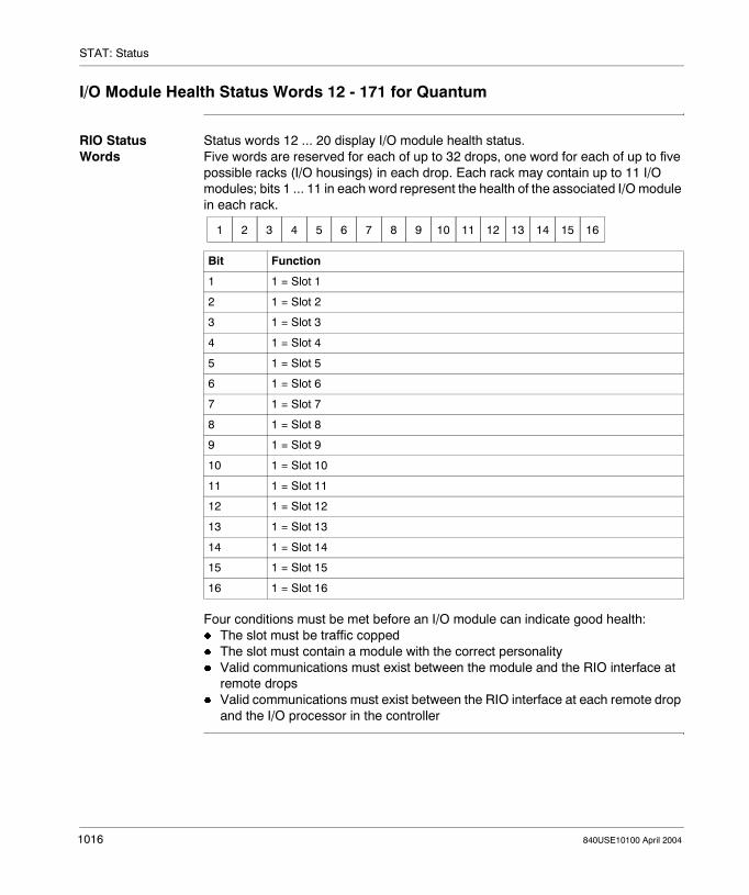
STAT: Status
I/O Module Health Status Words 12 - 171 for Quantum
RIO Status Words
Status words 12 ... 20 display I/O module health status.Five words are reserved for each of up to 32 drops, one word for each of up to five possible racks (I/O housings) in each drop. Each rack may contain up to 11 I/O modules; bits 1 ... 11 in each word represent the health of the associated I/O module in each rack.
Four conditions must be met before an I/O module can indicate good health:� The slot must be traffic copped� The slot must contain a module with the correct personality� Valid communications must exist between the module and the RIO interface at
remote drops� Valid communications must exist between the RIO interface at each remote drop
and the I/O processor in the controller
Bit Function
1 1 = Slot 1
2 1 = Slot 2
3 1 = Slot 3
4 1 = Slot 4
5 1 = Slot 5
6 1 = Slot 6
7 1 = Slot 7
8 1 = Slot 8
9 1 = Slot 9
10 1 = Slot 10
11 1 = Slot 11
12 1 = Slot 12
13 1 = Slot 13
14 1 = Slot 14
15 1 = Slot 15
16 1 = Slot 16
1 2 3 4 5 6 7 8 9 10 11 12 13 14 15 16
1016 840USE10100 April 2004

STAT: Status
Status Words for the MMI Operator Panels
The status of the 32 Element Pushbutton Panels and PanelMate units on an RIO network can also be monitored with an I/O health status word. The Pushbutton Panels occupy slot 4 in an I/O rack and can be monitored at bit 4 of the appropriate status word. A PanelMate on RIO occupies slot 1 in rack 1 of the drop and can be monitored at bit 1 of the first status word for the drop.
Note: The ASCII Keypad’s communication status can be monitored with the error codes in the ASCII READ/WRIT blocks.
840USE10100 April 2004 1017
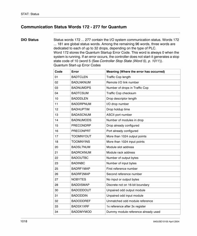
STAT: Status
Communication Status Words 172 - 277 for Quantum
DIO Status Status words 172 ... 277 contain the I/O system communication status. Words 172 ... 181 are global status words. Among the remaining 96 words, three words are dedicated to each of up to 32 drops, depending on the type of PLC.Word 172 stores the Quantum Startup Error Code. This word is always 0 when the system is running. If an error occurs, the controller does not start-it generates a stop state code of 10 (word 5 (See Controller Stop State (Word 5), p. 1011)).Quantum Start-up Error Codes
Code Error Meaning (Where the error has occurred)
01 BADTCLEN Traffic Cop length
02 BADLNKNUM Remote I/O link number
03 BADNUMDPS Number of drops in Traffic Cop
04 BADTCSUM Traffic Cop checksum
10 BADDDLEN Drop descriptor length
11 BADDRPNUM I/O drop number
12 BADHUPTIM Drop holdup time
13 BADASCNUM ASCII port number
14 BADNUMODS Number of modules in drop
15 PRECONDRP Drop already configured
16 PRECONPRT Port already configured
17 TOOMNYOUT More than 1024 output points
18 TOOMNYINS More than 1024 input points
20 BADSLTNUM Module slot address
21 BADRCKNUM Module rack address
22 BADOUTBC Number of output bytes
23 BADINBC Number of input bytes
25 BADRF1MAP First reference number
26 BADRF2MAP Second reference number
27 NOBYTES No input or output bytes
28 BADDISMAP Discrete not on 16-bit boundary
30 BADODDOUT Unpaired odd output module
31 BADODDIN Unpaired odd input module
32 BADODDREF Unmatched odd module reference
33 BAD3X1XRF 1x reference after 3x register
34 BADDMYMOD Dummy module reference already used
1018 840USE10100 April 2004

STAT: Status
Status of Cable A Words 173 ... 175 are Cable A error words:Word 173
Word 174
Word 175
35 NOT3XDMY 3x module not a dummy
36 NOT4XDMY 4x module not a dummy
40 DMYREAL1X Dummy, then real 1x module
41 REALDMY1X Real, then dummy 1x module
42 DMYREAL3X Dummy, then real 3x module
43 REALDMY3X Real, then dummy 3x module
Code Error Meaning (Where the error has occurred)
Bit Function
1 ... 8 Counts framing errors
9 ... 16 Counts DMA receiver overruns
Bit Function
1 ... 8 Counts receiver errors
9 ... 16 Counts bad drop receptions
Bit Function
1 1 = Short frame
2 1 = No end-of- frame
3 ... 12 Not used
13 1 = CRC error
14 1 = Alignment error
15 1 =Overrun error
16 Not used
1 2 3 4 5 6 7 8 9 10 11 12 13 14 15 16
1 2 3 4 5 6 7 8 9 10 11 12 13 14 15 16
1 2 3 4 5 6 7 8 9 10 11 12 13 14 15 16
840USE10100 April 2004 1019

STAT: Status
Status of Cable B Words 176 ... 178 are Cable A error words:Word 176
Word 177
Word 178
Bit Function
1 ... 8 Counts framing errors
9 ... 16 Counts DMA receiver overruns
Bit Function
1 ... 8 Counts receiver errors
9 -...16 Counts bad drop receptions
Bit Function
1 1 = Short frame
2 1 = No end-of- frame
3 ... 12 Not used
13 1 = CRC error
14 1 = Alignment error
15 1 =Overrun error
16 Not used
1 2 3 4 5 6 7 8 9 10 11 12 13 14 15 16
1 2 3 4 5 6 7 8 9 10 11 12 13 14 15 16
1 2 3 4 5 6 7 8 9 10 11 12 13 14 15 16
1020 840USE10100 April 2004

STAT: Status
Status of Global Communication (Words 179 ... 181)
Word 179 displays global communication status:
Word 180 is the global cumulative error counter for Cable A:
Word 181 is the global cumulative error counter for Cable B:
Status of Remote I/O (Words 182 ... 277)
Words 182 ... 277 are used to describe remote I/O drop status; three status words are used for each drop.The first word in each group of three displays communication status for the appropriate drop:
Bit Function
1 1 = Comm health
2 1 = Cable A status
3 1 = Cable B status
4 Not used
5 ... 8 Lost communication counter
9 ... 16 Cumulative retry counter
Bit Function
1 ... 8 Counts detected errors
9 ... 162 Counts No responses
Bit Function
1 ... 8 Counts detected errors
9 ... 162 Counts No responses
1 2 3 4 5 6 7 8 9 10 11 12 13 14 15 16
1 2 3 4 5 6 7 8 9 10 11 12 13 14 15 16
1 2 3 4 5 6 7 8 9 10 11 12 13 14 15 16
Bit Function
1 1 = Communication health
2 1 = Cable A status
3 1 = Cable B status
4 Not used
5 ... 8 Lost communication counter
9 ... 16 Cumulative retry counter
1 2 3 4 5 6 7 8 9 10 11 12 13 14 15 16
840USE10100 April 2004 1021

STAT: Status
The second word in each group of three is the drop cumulative error counter on Cable A for the appropriate drop:
The third word in each group of three is the drop cumulative error counter on Cable B for the appropriate drop:
Word 182 displays local drop status:
Word 183 is a 16-bit error counter, which indicates the number of times a module has been accessed and found to be unhealthy. Rolls over at 65535.
Word 184 is a 16-bit error counter, which indicates the number of times a communication error occurred while accessing an I/O module. Rolls over at 65535.
Bit Function
1 ... 8 At least one error in words 173 ...175
9 ... 162 Counts No responses
Bit Function
1 ... 8 At least one error in words 176 ...178
9 ... 162 Counts No responses
Note: For PLCs where drop 1 is reserved for local I/O, status words 182 ... 184 are used as follows:
Bit Function
1 1 = All modules healthy
2 ... 8 Always 0
9 ... 162 Number of times a module has been seen as unhealthy; counter rolls over at 255
1 2 3 4 5 6 7 8 9 10 11 12 13 14 15 16
1 2 3 4 5 6 7 8 9 10 11 12 13 14 15 16
1 2 3 4 5 6 7 8 9 10 11 12 13 14 15 16
1022 840USE10100 April 2004

STAT: Status
Controller Status Words 1 - 11 for TSX Compact and Atrium
CPU Status (Word 1)
Word 1 displays the following aspects of the CPU status:
Word 2 This word is not used.
Controller Status (Word 3)
Word 3 displays aspects of the controller status:
Word 4 This word is not used.
Bit Function
1 - 5 Not used
6 1 = enable constant sweep
7 1 = enable single sweep delay
8 1 = 16 bit user logic0 = 24 bit user logic
9 1 = AC power on
10 1 = RUN light OFF
11 1 = memory protect OFF
12 1 = battery failed
13 - 16 Not used
1 2 3 4 5 6 7 8 9 10 11 12 13 14 15 16
Bit Function
1 1 = first scan
2 1 = start command pending
3 1 = scan time has exceed constant scan target
4 1 = existing DIM AWARENESS
5 - 12 Not used
13 - 16 Single sweeps
1 2 3 4 5 6 7 8 9 10 11 12 13 14 15 16
840USE10100 April 2004 1023

STAT: Status
CPU Stop State (Word 5)
Word 5 displays the CPU’s stop state conditions:
Number of Segments in program (Word 6)
Word 6 displays the number of segments in ladder logic; a binary number is shown. This word is confirmed during power up to be the number of EOS (DOIO) nodes plus 1 (for the end of logic nodes), if untrue, a stop code is set, causing the run light to be off:
Bit Function
1 1 = peripheral port stop
2 1 = XMEM parity error
3 1 = DIM AWARENESS
4 1 = illegal peripheral intervention
5 1 = invalid segment scheduler
6 1 = no start-of-network (SON) at the start of a segment
7 1 = state RAM test failed
8 1 = no end of logic (EOL), (bad Tcop)
9 1 = watch dog timer has expired
10 1 = real time clock error
11 1 = CPU failure
12 Not used
13 1 = invalid node in ladder logic
14 1 = logic checksum error
1 1 = coil disabled in RUN mode
16 1 = bad PLC setup
1 2 3 4 5 6 7 8 9 10 11 12 13 14 15 16
Bit Function
1 - 16 Number of segments in the current ladder logic program (expressed as a decimal number)
1 2 3 4 5 6 7 8 9 10 11 12 13 14 15 16
1024 840USE10100 April 2004

STAT: Status
Address of the End of Logic Pointer (Word 7)
Word 7 displays the address of the end-of-logic (EOL) pointer:
Word 8, Word 9 These words are not used.
RUN/LOAD/DEBUG Status (Word 10)
Word 10 uses its two least significant bits to display RUN/LOAD/DEBUG status:
Word 11 This word is not used.
Bit Function
1 - 16 EOL pointer address
1 2 3 4 5 6 7 8 9 10 11 12 13 14 15 16
Bit Function
1 ... 14 Not used
15, 16 0 0 = Debug (0 dec)0 1 = Run (1 dec)1 0 = Load (2 dec)
1 2 3 4 5 6 7 8 9 10 11 12 13 14 15 16
840USE10100 April 2004 1025

STAT: Status
I/O Module Health Status Words 12 - 15 for TSX Compact
TSX Compact I/O Module Health
Words 12 ... 15 are used to display the health of the A120 I/O modules in the four racks:
Each word contains the health status of up to five A120 I/O modules. The most significant (left-most) bit represents the health of the module in Slot 1 of the rack:
If a module is I/O Mapped and ACTIVE, the bit will have a value of "1". If a module is inactive or not I/O Mapped, the bit will have a value of "0".
Word Rack No.
12 1
13 2
14 3
15 4
Bit Function
1 1 = Slot 1
2 1 = Slot 2
3 1 = Slot 3
4 1 = Slot 4
5 1 = Slot 5
6 ... 16 Not used
Note: Slots 1 and 2 in Rack 1 (Word 12) are not used because the controller itself uses those two slots.
1 2 3 4 5 6 7 8 9 10 11 12 13 14 15 16
1026 840USE10100 April 2004

STAT: Status
Global Health and Communications Retry Status Words 182 ... 184 for TSX Compact
Overview There are three words that contain health and communication information on the installed I/O modules. If monitored with the Stat block, they are found in Words 182 through 184. This requires that the length of the Stat block is a minimum of 184 (Words 16 through 181 are not used).
Words 16 ... 181 These words are not used.
Health Status (Word 182)
Word 182 increments each time a module becomes bad. After a module becomes bad, this counter does not increment again until that module becomes good and then bad again.
I/O Error Counter (Word 183)
This counter is similar to the above counter, except this word increments every scan that a module remains in the bad state.
PAB Bus Retry Counter (Word 184)
Diagnostics are performed on the communications through the bus. This word should normally be all zeroes. If after 5 retries, a bus error is still detected, the controller will stop and error code 10 will be displayed. An error could occur if there is a short in the backplane or from noise. The counter rolls over while running. If the retries are less than 5, no bus error is detected.
Bit Function
1 1 = All modules healthy
2 ... 9 Not used
10 ... 16 "Module went unhealthy" counter
1 2 3 4 5 6 7 8 9 10 11 12 13 14 15 16
840USE10100 April 2004 1027

STAT: Status
1028 840USE10100 April 2004

840USE10100 April 2004
160
SU16: Subtract 16 BitAt a Glance
Introduction This chapter describes the instruction SU16.
What's in this Chapter?
This chapter contains the following topics:
Topic Page
Short Description 1030
Representation: SU16 - 16-bit Subtraction 1031
1029

SU16: Subtract 16 Bit
Short Description
Function Description
The SU16 instruction performs a signed or unsigned 16-bit subtraction (value 1 - value 2) on the top and middle node values, then posts the signed or unsigned difference in a 4x holding register in the bottom node.
1030 840USE10100 April 2004

SU16: Subtract 16 Bit
Representation: SU16 - 16-bit Subtraction
Symbol Representation of the instruction
Parameter Description
Description of the instruction’s parameters
SU16
difference
Value 2
Value 1CONTROL INPUT TOP VALUE > MIDDLE VALUE
(+ result)
TOP VALUE < MIDDLE VALUE(- result)
SIGNED
TOP VALUE = MIDDLE VALUE(zero result)
Max. Value65535
Max. Value65535
Parameters State RAM Reference
Data Type Meaning
Top input 0x, 1x None ON = enables value 1 - value 2
Bottom input 0x, 1x None ON = signed operationOFF = unsigned operation
value 1(top node)
3x, 4x INT, UINT Minuend, can be displayed explicitly as an integer (range 1 ... 65 535) or stored in a register
value 2(middle node)
3x, 4x INT, UINT Subtrahend, can be displayed explicitly as an integer (range 1 ... 65 535) or stored in a register
difference(bottom node)
4x INT, UINT Difference
Top output 0x None ON = value 1 > value 2
Middle output 0x None ON = value 1 = value 2
Bottom output 0x None ON = value 1 < value 2
840USE10100 April 2004 1031

SU16: Subtract 16 Bit
1032 840USE10100 April 2004

840USE10100 April 2004
161
SUB: SubtractionAt a Glance
Introduction This chapter describes the instruction SUB.
What's in this Chapter?
This chapter contains the following topics:
Topic Page
Short Description 1034
Representation: SUB - Subtraction 1035
1033
SUB: Subtraction
Short Description
Function Description
The SUB instruction performs a signed or unsigned 16-bit subtraction (value 1 - value 2) on the top and middle node values, then posts the signed or unsigned difference in a 4x holding register in the bottom node.
Note: SUB is often used as a comparator where the state of the outputs identifies whether value 1 is greater than, equal to, or less than value 2.
1034 840USE10100 April 2004

SUB: Subtraction
Representation: SUB - Subtraction
Symbol Representation of the instruction
Parameter Description
Description of the instruction’s parameters
CONTROL INPUT TOP VALUE > MIDDLE VALUE(+ result)
TOP VALUE = MIDDLE VALUE(zero result)
TOP VLUE < MIDDLE VALUE(- result)
value 1
value 2
SUB
difference
Max. 999 16-bit PLC9999 24-bit PLC65535-785L
Max. 999 16-bit PLC9999 24-bit PLC65535-785L
Parameters State RAM Reference
Data Type Meaning
Top input 0x, 1x None ON = enables value 1 - value 2
value 1(top node)
3x, 4x INT, UINT Minuend, can be displayed explicitly as an integer or stored in a registerMax. 255 16-bit PLCMax. 999 24-bit PLCMax. 65535-785L
value 2(middle node)
3x, 4x INT, UINT Subtrahend, can be displayed explicitly as an integer or stored in a registerMax. 255 16-bit PLCMax. 999 24-bit PLCMax. 65535-785L
difference(bottom node)
4x INT, UINT Difference
Top output 0x None ON = value 1 > value 2
Middle output 0x None ON = value 1 = value 2
Bottom output 0x None ON = value 1 < value 2
840USE10100 April 2004 1035

SUB: Subtraction
1036 840USE10100 April 2004

840USE10100 April 2004
162
SWAP - VME Bit SwapAt A Glance
Introduction This chapter describes the instruction SWAP.
What's in this Chapter?
This chapter contains the following topics:
Topic Page
Short Description: SWAP - VME Bit Swap 1038
Representation: SWAP - VME Bit Swap 1039
1037

SWAP - VME Bit Swap
Short Description: SWAP - VME Bit Swap
Function Description
The SWAP block allows the user to issue one of three different swap commands:� Swap high and low bits of a 16-bit word.� Swap high and low words of a 32-bit double word.� Swap (reverse) bits within a register's low byte.
Note: Available only on the Quantum VME-424/X controller.
1038 840USE10100 April 2004

SWAP - VME Bit Swap
Representation: SWAP - VME Bit Swap
Symbol Representation of the instruction
Parameter Description
Description of the instruction’s parameters
CONTROL INPUT ACTIVE
ERROR
COMPLETE
value
register
SWAP
# of registers
Parameters State RAM Reference
Data Type Meaning
Top input 0x, 1x None ON enables SWAP operation
value(top node)
INT, UINT, WORD
Contains a constant from 1 to 3, which specifies what type of swap to perform:1. Swap high and low bits of a 16-bit word.2. Swap high and low words of a 32-bit
double word.3. Swap (reverse) bits within a register's
low byte.
register(middle node)
3x, 4x INT, UINT, WORD
Contains the register on which the swap is to be performed
# of registers(bottom node)
INT, UINT, WORD
Contains a constant that indicates how many registers are to be swapped, starting with the source register.
Top output 0x None Echoes the state of the top input
Middle output 0x None Error
Bottom output 0x None Swap completed successfully
840USE10100 April 2004 1039

SWAP - VME Bit Swap
1040 840USE10100 April 2004

840USE10100 April 2004
163
TTR - Table to RegisterAt A Glance
Introduction This chapter describes the instruction TTR.
What's in this Chapter?
This chapter contains the following topics:
Topic Page
Short Description: TTR - Table to Register 1042
Representation: TTR - Table to Register 1043
1041

TTR - Table to Register
Short Description: TTR - Table to Register
Function Description
The Table to Register block is one of four 484-replacement instructions.It copies the contents of a source (input or holding) register to a holding register implied by the constant in the bottom node. This source register is pointed to by the input or holding register specified in the top node. Only one such operation can be accommodated by the system in each scan.
Note: Available only on the 984-351 and 984-455.
1042 840USE10100 April 2004
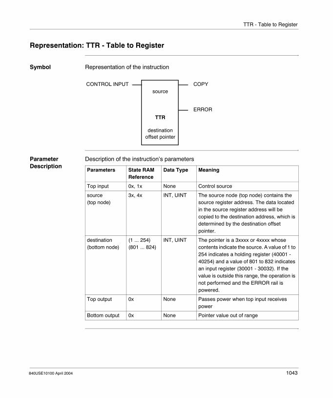
TTR - Table to Register
Representation: TTR - Table to Register
Symbol Representation of the instruction
Parameter Description
Description of the instruction’s parameters
CONTROL INPUT COPY
ERROR
source
TTR
destinationoffset pointer
Parameters State RAM Reference
Data Type Meaning
Top input 0x, 1x None Control source
source(top node)
3x, 4x INT, UINT The source node (top node) contains the source register address. The data located in the source register address will be copied to the destination address, which is determined by the destination offset pointer.
destination(bottom node)
(1 ... 254)(801 ... 824)
INT, UINT The pointer is a 3xxxx or 4xxxx whose contents indicate the source. A value of 1 to 254 indicates a holding register (40001 - 40254) and a value of 801 to 832 indicates an input register (30001 - 30032). If the value is outside this range, the operation is not performed and the ERROR rail is powered.
Top output 0x None Passes power when top input receives power
Bottom output 0x None Pointer value out of range
840USE10100 April 2004 1043

TTR - Table to Register
1044 840USE10100 April 2004

840USE10100 April 2004
164
T --> R Table to RegisterAt a Glance
Introduction This chapter describes the instruction T→R.
What's in this Chapter?
This chapter contains the following topics:
Topic Page
Short Description 1046
Representation: T → R - Table to Register Move 1047
Parameter Description 1049
1045

T --> R: Table to Register
Short Description
Function Description
The T→R instruction copies the bit pattern of a register or 16 contiguous discretes in a table to a specific holding register. It can accommodate the transfer of one register per scan. It has three control inputs and produces two possible outputs.
1046 840USE10100 April 2004
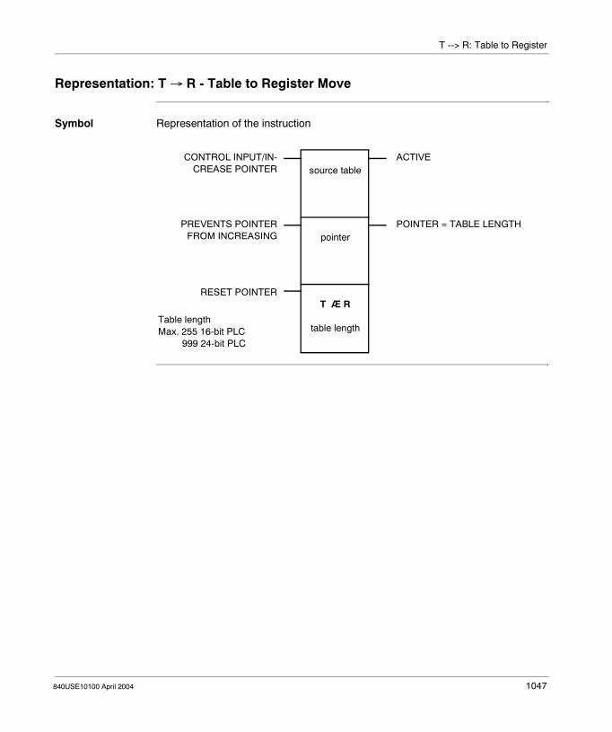
T --> R: Table to Register
Representation: T → R - Table to Register Move
Symbol Representation of the instruction
CONTROL INPUT/IN-CREASE POINTER
PREVENTS POINTERFROM INCREASING
RESET POINTER
ACTIVE
POINTER = TABLE LENGTH
Table lengthMax. 255 16-bit PLC 999 24-bit PLC
source table
pointer
T Æ R
table length
840USE10100 April 2004 1047

T --> R: Table to Register
Parameter Description
Description of the instruction’s parameters
Parameters State RAM Reference
Data Type Meaning
Top input 0x, 1x None ON = copies source data and increments the pointer value
Middle input (See Middle Input, p. 1049)
0x, 1x None ON = freezes the pointer value
Bottom input (See Bottom Input, p. 1049)
0x, 1x None ON = resets the pointer value to zero
source table(top node)
0x, 1x, 3x, 4x INT, UINT, WORD
First register or discrete reference in the source table. A register or string of contiguous discretes from this table will be copied in a scan.
pointer (See Pointer (Middle Node), p. 1049)(middle node)
4x INT, UINT Pointer to the destination where the source data will be copied
table length(bottom node)
INT, UINT Length of the source table: number of registers that may be copied; range: 1 ... 999Length:Max. 255 16-bit PLCMax. 999 24-bit PLC
Top output 0x None Echoes the state of the top input
Middle output 0x None ON = pointer value = table length (instruction cannot increment any further)
1048 840USE10100 April 2004

T --> R: Table to Register
Parameter Description
Middle Input When the middle input goes ON, the current value stored in the pointer register is frozen while the DX operation continues. This causes the same table data to be written to the destination register on each scan.
Bottom Input When the bottom input goes ON, the value in the pointer is reset to zero. This causes the next DX move operation to copy the first destination register in the table.
Pointer (Middle Node)
The 4x register entered in the middle node is a pointer to the destination where the source data will be copied. The destination register is the next contiguous 4x register after the pointer. For example, if the middle node displays a pointer of 400100, then the destination register for the T→R copy is 400101.The value stored in the pointer register indicates which register in the source table will be copied to the destination register in the current scan. A value of 0 in the pointer indicates that the bit pattern in the first register of the source table will be copied to the destination; a value of 1 in the pointer register indicates that the bit pattern in the second register of the source table will be copied to the destination register; etc.
840USE10100 April 2004 1049

T --> R: Table to Register
1050 840USE10100 April 2004

840USE10100 April 2004
165
T --> T: Table to TableAt a Glance
Introduction This chapter describes the instruction T→T.
What's in this Chapter?
This chapter contains the following topics:
Topic Page
Short Description 1052
Representation: T → T - Table to Table Move 1053
Parameter Description 1055
1051

T --> T: Table to Table
Short Description
Function Description
The T→T instruction copies the bit pattern of a register or of 16 discretes from a position within one table to an equivalent position in another table of registers. It can accommodate the transfer of one register per scan. It has three control inputs and produces two possible outputs.
1052 840USE10100 April 2004

T --> T: Table to Table
Representation: T → T - Table to Table Move
Symbol Representation of the instruction
*Available on the following� E685/785 PLCs� L785 PLCs� Quantum Series PLCs
CONTROL INPUT/IN-CREASE POINTER
PREVENTS POINTERFROM INCREASING
RESET POINTER
ACTIVE
POINTER = TABLE LENGTH
Table lengthMax. 255 16-bit PLC 999 24-bit PLC 65535 *PLC
source table
pointer
T Æ T
table length
840USE10100 April 2004 1053

T --> T: Table to Table
Parameter Description
Description of the instruction’s parameters
Parameters State RAM Reference
Data Type Meaning
Top input 0x, 1x None ON = copies source data and increments the pointer value
Middle input (See Middle Input, p. 1055)
0x, 1x None ON = freezes the pointer value
Bottom input (See Bottom Input, p. 1055)
0x, 1x None ON = resets the pointer value to zero
source table(top node)
0x, 1x, 3x, 4x INT, UINT, WORD
First register or discrete reference in the source table. A register or string of contiguous discretes from this table will be copied in a scan.
pointer (See Pointer (Middle Node), p. 1055)(middle node)
4x INT, UINT Pointer into both the source and destination table
table length(bottom node)
INT, UINT Length of the source and the destination table (must be equal in length)Range:Max. 255 16-bit PLCMax. 999 24-bit PLCMax. 65535 785L
Top output 0x None Echoes the state of the top input
Middle output 0x None ON = pointer value = table length (instruction cannot increment any further)
1054 840USE10100 April 2004

T --> T: Table to Table
Parameter Description
Middle Input When the input to the middle node goes ON, the current value stored in the pointer register is frozen while the DX operation continues. This causes new data being copied to the destination to overwrite the data copied on the previous scan.
Bottom Input When the input to the bottom node goes ON, the value in the pointer register is reset to zero. This causes the next DX move operation to copy source data into the first register in the destination table.
Pointer (Middle Node)
The 4x register entered in the middle node is a pointer into both the source and destination tables, indicating where the data will be copied from and to in the current scan. The first register in the destination table is the next contiguous 4x register following the pointer. For example, if the middle node displays a a pointer reference of 400100, then the first register in the destination table is 400101.The value stored in the pointer register indicates which register in the source table will be copied to which register in the destination table. Since the length of the two tables is equal and T→T copy is to the equivalent register in the destination table, the current value in the pointer register also indicates which register in the destination table the source data will be copied to.A value of 0 in the pointer register indicates that the bit pattern in the first register of the source table will be copied to the first register of the destination table; a value of 1 in the pointer register indicates that the bit pattern in the second register of the source table will be copied to the second register of the destination register; etc.
840USE10100 April 2004 1055

T --> T: Table to Table
1056 840USE10100 April 2004
840USE10100 April 2004
166
T.01 Timer: One Hundredth Second TimerAt a Glance
Introduction This chapter describes the instruction T.01 Timer.
What's in this Chapter?
This chapter contains the following topics:
Topic Page
Short Description 1058
Representation: T.01 - One Hundredth of a Second Timer 1059
1057

T.01 Timer: One Hundredth Second Timer
Short Description
Function Description
The T.01 instruction measures time in hundredth of a second intervals. It can be used for timing an event or creating a delay. T.01 has two control inputs and can produce one of two possible outputs.
1058 840USE10100 April 2004

T.01 Timer: One Hundredth Second Timer
Representation: T.01 - One Hundredth of a Second Timer
Symbol Representation of the instruction
Parameter Description
Description of the instruction’s parameters
CONTROL INPUT
ENABLE/RESET
TIMER = PRESET
TIMER < PRESET
timer preset
T.01
accumulated time
Max. 999 16-bit PLC 9999 24-bit PLC 65535 - 785L
Parameters State RAM Reference
Data Type Meaning
Top input 0x, 1x None OFF → ON = initiates the timer operation: time accumulates in hundredths-of-a-second when top and bottom input are ON
Bottom input 0x, 1x None OFF = accumulated time reset to 0ON = timer accumulating
timer preset(top node)
3x, 4x INT, UINT Preset value (number of hundredth-of-a-second increments), can be displayed explicitly as an integer or stored in a registerRange:Max. 255 16-bit PLCMax. 999 24-bit PLCMax. 65535 785L
accumulated time(bottom node)
4x INT, UINT Accumulated time count in hundredth-of-a-second increments.
Top output 0x None ON = accumulated time = timer preset
Bottom output 0x None ON = accumulated time < timer preset
840USE10100 April 2004 1059

T.01 Timer: One Hundredth Second Timer
1060 840USE10100 April 2004
840USE10100 April 2004
167
T0.1 Timer: One Tenth Second TimerAt a Glance
Introduction This chapter describes the instruction T0.1 Timer.
What's in this Chapter?
This chapter contains the following topics:
Topic Page
Short Description 1062
Representation: T0.1 - One Tenth of a Second Timer 1063
1061

T0.1 Timer: One Tenth Second Timer
Short Description
Function Description
The T0.1 instruction measures time in tenth-of-a-second increments. It can be used for timing an event or creating a delay. T0.1 has two control inputs and can produce one of two possible outputs.
Note: If you cascade T0.1 timers with presets of 1, the timers will time-out together; to avoid this problem, change the presets to 10 and substitute a T.01 timer (See T.01 Timer: One Hundredth Second Timer, p. 1057).
1062 840USE10100 April 2004

T0.1 Timer: One Tenth Second Timer
Representation: T0.1 - One Tenth of a Second Timer
Symbol Representation of the instruction
Parameter Description
Description of the instruction’s parameters
CONTROL INPUT
ENABLE/RESET
TIMER = PRESET
TIMER < PRESET
timer preset
T0.1
accumulated time
Max. 999 16-bit PLC 9999 24-bit PLC 65535 - 785L
Parameters State RAM Reference
Data Type Meaning
Top input 0x, 1x None OFF → ON = initiates the timer operation: time accumulates in tenth-of-a-second when top and bottom input are ON
Bottom input 0x, 1x None OFF = accumulated time reset to 0ON = timer accumulating
timer preset(top node)
3x, 4x INT, UINT Preset value (number of tenth-of-a-second increments), can be displayed explicitly as an integer or stored in a registerRange:Max. 255 16-bit PLCMax. 999 24-bit PLCMax. 65535 785L
accumulated time(bottom node)
4x INT, UINT Accumulated time count in tenth-of-a-second increments.
Top output 0x None ON = accumulated time = timer preset
Bottom output 0x None ON = accumulated time < timer preset
840USE10100 April 2004 1063

T0.1 Timer: One Tenth Second Timer
1064 840USE10100 April 2004
840USE10100 April 2004
168
T1.0 Timer: One Second TimerAt a Glance
Introduction This chapter describes the instruction T1.0 Timer.
What's in this Chapter?
This chapter contains the following topics:
Topic Page
Short Description 1066
Representation: T1.0 - One Second Timer 1067
1065

T1.0 Timer: One Second Timer
Short Description
Function Description
The T1.0 timer instruction measures time in one-second increments. It can be used for timing an event or creating a delay. T1.0 has two control inputs and can produce one of two possible outputs.
Note: If you cascade T1.0 timers with presets of 1, the timers will time-out together; to avoid this problem, change the presets to 10 and substitute a T0.1 timer (See T0.1 Timer: One Tenth Second Timer, p. 1061).
1066 840USE10100 April 2004

T1.0 Timer: One Second Timer
Representation: T1.0 - One Second Timer
Symbol Representation of the instruction
Parameter Description
Description of the instruction’s parameters
CONTROL INPUT
ENABLE / RESET
TIMER = PRESET
TIMER < PRESET
timer preset
T1.0
accumulated time
Max. 999 16-bit PLC 9999 24-bit PLC 65535 - 785L
Parameters State RAM Reference
Data Type Meaning
Top input 0x, 1x None OFF → ON = initiates the timer operation: time accumulates in seconds when top and bottom input are ON
Bottom input 0x, 1x None OFF = accumulated time reset to 0ON = timer accumulating
timer preset(top node)
3x, 4x INT, UINT Preset value (number of one second increments), can be displayed explicitly as an integer or stored in a registerRange:Max. 255 16-bit PLCMax. 999 24-bit PLCMax. 65535 785L
accumulated time(bottom node)
4x INT, UINT Accumulated time count in one-second increments.
Top output 0x None ON = accumulated time = timer preset
Bottom output 0x None ON = accumulated time < timer preset
840USE10100 April 2004 1067

T1.0 Timer: One Second Timer
1068 840USE10100 April 2004

840USE10100 April 2004
169
T1MS Timer: One Millisecond TimerAt a Glance
Introduction This chapter describes the instruction T1MS Timer.
What's in this Chapter?
This chapter contains the following topics:
Topic Page
Short Description 1070
Representation: T1MS - One Millisecond Timer 1071
Example 1072
1069

T1MS Timer: One Millisecond Timer
Short Description
Function Description
The T1MS timer instruction measures time in one-millisecond increments. It can be used for timing an event or creating a delay.
Note: The T1MS instruction is available only on the B984-102, the Micro 311, 411, 512, and 612, and the Quantum 424 02.
1070 840USE10100 April 2004

T1MS Timer: One Millisecond Timer
Representation: T1MS - One Millisecond Timer
Symbol Representation of the instruction
Parameter Description
Description of the instruction’s parameters
CONTROL INPUT
ENABLE/RESET
TIMER = PRESET
TIMER < PRESET
timer preset
accumulated time
T1MS
#1
Preset valueMax. 999 (in ms.)
Parameters State RAM Reference
Data Type Meaning
Top input 0x, 1x None ON = initiates the timer operation: time accumulates in milliseconds when top and middle input are ON
Middle input 0x, 1x None OFF = accumulated time reset to 0ON = timer accumulating
timer preset(top node)
3x, 4x INT, UINT Preset value (number of millisecond increments the timer can accumulate), can be displayed explicitly as an integer (range 1 ... 999) or stored in a register
accumulated time(middle node)
4x INT, UINT Accumulated time count in millisecond increments.
#1(bottom node)
INT, UINT Constant value of #1
Top output 0x None ON = accumulated time = timer preset
Middle output 0x None ON = accumulated time < timer preset
840USE10100 April 2004 1071

T1MS Timer: One Millisecond Timer
Example
A Millisecond Timer Example
Here is the ladder logic for a real-time clock with millisecond accuracy:
The T1MS instruction is programmed to pass power at 100 ms intervals; it is followed by a cascade of four up-counters (See UCTR: Up Counter, p. 1083) that store the time respectively in hundredth-of-a-second units, tenth-of-a-second units, one- second units, one-minute units, and one-hour units.When logic solving begins, the accumulated time value begins incrementing in register 40055 of the T1MS block. After 100 one-ms increments, the top output passes power and energizes coil 00001. At this point, the value in register 40055 in the timer is reset to 0. The accumulated count value in register 40054 in the first UCTR block increments by 1, indicating that 100 ms have passed. Because the accumulated time count in T1MS no longer equals the timer preset, the timer begins to re-accumulate time in ms.When the accumulated count in register 40054 of the first UCTR instruction increments to 10, the top output from that instruction block passes power and energizes coil 00002. The value in register 40054 then resets to 0, and the accumulated count in register 40053 of the second UCTR block increments by 1.As the times accumulate in each counter, the time of day can be read in five holding registers as follows:
Register Unit of Time Valid Range
40055 Thousandths-of-a-second 0 ... 100
40054 Tenths-of-a-second 0 ... 10
40053 Seconds 0 ... 60
40052 Minutes 0 ... 60
40051 Hours 0 ... 24
000001
000001
100
T1MS
400055
1
UCTR
10
400054
000002
UCTR
60
400053
000003
UCTR
60
400052
000004
UCTR
24
400051
000005
000002
000003
000004
000005
1072 840USE10100 April 2004
840USE10100 April 2004
170
TBLK: Table to BlockAt a Glance
Introduction This chapter describes the instruction TBLK.
What's in this Chapter?
This chapter contains the following topics:
Topic Page
Short Description 1074
Representation: TBLK - Table-to-Block Move 1075
Parameter Description 1077
1073

TBLK: Table to Block
Short Description
Function Description
The TBLK (table-to-block) instruction combines the functions of T→R (See T --> R Table to Register, p. 1045) and the BLKM (See BLKM: Block Move, p. 135) in a single instruction. In one scan, it can copy up to 100 contiguous 4x registers from a table to a destination block. The destination block is of a fixed length. The block of registers being copied from the source table is of the same length, but the overall length of the source table is limited only by the number of registers in your system configuration.
1074 840USE10100 April 2004

TBLK: Table to Block
Representation: TBLK - Table-to-Block Move
Symbol Representation of the instruction
CONTROL INPUT
HOLD POINTER
RESET POINTER
OPERATION SUCCESSFUL
ERROR
source table
pointer
TBLK
block length
840USE10100 April 2004 1075

TBLK: Table to Block
Parameter Description
Description of the instruction’s parameters
Parameters State RAM Reference
Data Type
Meaning
Top input 0x, 1x None ON = initiates move operation
Middle input (See Middle Input, p. 1077)
0x, 1x None ON = hold pointerThe inputs to the middle and bottom node can be used to control the value in the pointer so that size of the source table can be controlled.Important: You should use external logic in conjunction with the middle or bottom input to confine the value in the destination pointer to a safe range.When the input to the middle node is ON, the value in the pointer register is frozen while the TBLK operation continues. This causes the same source data block to be copied to the destination table on each scan.
Bottom input (See Bottom Input, p. 1077)
0x, 1x None ON = reset pointer to zero
source table (See Source Table (Top Node), p. 1077)(top node)
4x INT, UINT, WORD
First holding register in the source tableThe 4xxxx register entered in the top node is the first holding register in the source table.Note: The source table is segmented into a series of register blocks, each of which is the same length as the destination block. Therefore, the size of the source table is a multiple of the length of the destination block, but its overall size is not specifically defined in the instruction. If left uncontrolled, the source table could consume all the 4xxxx registers available in the PLC configuration.
pointer (See Pointer (Middle Node), p. 1077)(middle node)
4x INT, UINT
Pointer to the source block, destination block
block length(bottom node)
INT, UINT
Number of registers of the destination block and of the blocks within the source table; range: 1 ... 100
Top output 0x None ON = move successful
Middle output 0x None ON = error / move not possible
1076 840USE10100 April 2004

TBLK: Table to Block
Parameter Description
Middle Input When the middle input is ON, the value in the pointer register is frozen while the TBLK operation continues. This causes the same source data block to be copied to the destination table on each scan.
Bottom Input When the bottom input is ON, the pointer value is reset to zero. This causes the TBLK operation to copy data from the first block of registers in the source table.
Source Table (Top Node)
The 4x register entered in the top node is the first holding register in the source table.
Pointer (Middle Node)
The 4x register entered in the middle node is the pointer to the source block. The first register in the destination block is the next contiguous register after the pointer. For example, if the pointer is register 400107, then the first register in the destination block is 400108.The value stored in the pointer indicates which block of data from the source table will be copied to the destination block. This value specifies a block number within the source table.
CAUTION
Confine the value in the destination pointer to a safe range.
You should use external logic in conjunction with the middle and the bottom inputs to confine the value in the destination pointer to a safe range.
Failure to follow this precaution can result in injury or equipment damage.
Note: The source table is segmented into a series of register blocks, each of which is the same length as the destination block. Therefore, the size of the source table is a multiple of the length of the destination block, but its overall size is not specifically defined in the instruction. If left uncontrolled, the source table could consume all the 4x registers available in the PLC configuration.
840USE10100 April 2004 1077

TBLK: Table to Block
1078 840USE10100 April 2004

840USE10100 April 2004
171
TEST: Test of 2 ValuesAt a Glance
Introduction This chapter describes the instruction TEST.
What's in this Chapter?
This chapter contains the following topics:
Topic Page
Short Description 1080
Representation: TEST - Test of 2 Values 1081
1079
TEST: Test of 2 Values
Short Description
Function Description
The TEST instruction compares the signed or unsigned size of the 16-bit values in the top and middle nodes and describes the relationship via the block outputs.
1080 840USE10100 April 2004

TEST: Test of 2 Values
Representation: TEST - Test of 2 Values
Symbol Representation of the instruction
Parameter Description
Description of the instruction’s parameters
CONTROL INPUT
SIGNED
TOP VALUE > MIDDLE VALUE
TOP VALUE = MIDDLE VALUE
TOP VALUE < MIDDLE VALUE
value 1
value 2
TEST
# 1
Max. value: 65535
Max. value: 65535
Parameters State RAM Reference
Data Type Meaning
Top input 0x, 1x None ON = compares value 1 and value 2
Bottom input 0x, 1x None ON = signed operationOFF = unsigned operation
value 1(top node)
3x, 4x INT, UINT Value 1, can be displayed explicitly as an integer (range 1 ... 65 535) or stored in a register
value 2(middle node)
3x, 4x INT, UINT Value 2, can be displayed explicitly as an integer (range 1 ... 65 535) or stored in a register
1(bottom node)
INT, UINT Constant value, cannot be changed
Top output 0x None ON = value 1 > value 2
Middle output 0x None ON = value 1 = value 2
Bottom output 0x None ON = value 1 < value 2
840USE10100 April 2004 1081

TEST: Test of 2 Values
1082 840USE10100 April 2004
840USE10100 April 2004
172
UCTR: Up CounterAt a Glance
Introduction This chapter describes the instruction UCTR.
What's in this Chapter?
This chapter contains the following topics:
Topic Page
Short Description 1084
Representation: UCTR - Up Counter 1085
1083

UCTR: Up Counter
Short Description
Function Description
The UCTR instruction counts control input transitions from OFF to ON up from zero to a counter preset value.
1084 840USE10100 April 2004
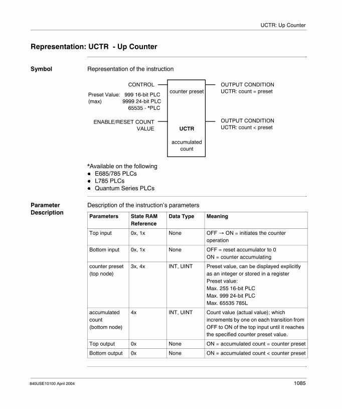
UCTR: Up Counter
Representation: UCTR - Up Counter
Symbol Representation of the instruction
*Available on the following� E685/785 PLCs� L785 PLCs� Quantum Series PLCs
Parameter Description
Description of the instruction’s parameters
CONTROL
ENABLE/RESET COUNTVALUE
OUTPUT CONDITIONUCTR: count = preset
Preset Value: 999 16-bit PLC(max) 9999 24-bit PLC 65535 - *PLC
OUTPUT CONDITIONUCTR: count < preset
counter preset
UCTR
accumulated count
Parameters State RAM Reference
Data Type Meaning
Top input 0x, 1x None OFF → ON = initiates the counter operation
Bottom input 0x, 1x None OFF = reset accumulator to 0ON = counter accumulating
counter preset(top node)
3x, 4x INT, UINT Preset value, can be displayed explicitly as an integer or stored in a registerPreset value:Max. 255 16-bit PLCMax. 999 24-bit PLCMax. 65535 785L
accumulated count(bottom node)
4x INT, UINT Count value (actual value); which increments by one on each transition from OFF to ON of the top input until it reaches the specified counter preset value.
Top output 0x None ON = accumulated count = counter preset
Bottom output 0x None ON = accumulated count < counter preset
840USE10100 April 2004 1085

UCTR: Up Counter
1086 840USE10100 April 2004

840USE10100 April 2004
173
VMER - VME ReadAt A Glance
Introduction This chapter describes the instruction VMER.
What's in this Chapter?
This chapter contains the following topics:
Topic Page
Short Description: VMER - VME Read 1088
Representation: VMER - VME Read 1089
Parameter Description: VMER - VME Read 1090
1087

VMER - VME Read
Short Description: VMER - VME Read
Function Description
The VME Read block allows the user to read data from devices on the VME bus. If Byte Swap is active, the high byte is exchanged with the low byte of a word after it is read from the VME bus. If Word Swap is enabled, the upper word is exchanged with the lower word of a double after it is read. An error will occur if both inputs are enabled at once.
Note: Available only on the Quantum VME-424/X controller.
1088 840USE10100 April 2004

VMER - VME Read
Representation: VMER - VME Read
Symbol Representation of the instruction
Parameter Description
Description of the instruction’s parameters
CONTROL INPUT
BYTE SWAP
WORD SWAP
ACTIVE
ERROR
COMPLETE
register
pointer
VMER
value(1 ... 255)
Parameters State RAM Reference
Data Type Meaning
Top input 0x, 1x None ON enables read
Middle input 0x, 1x None ON = byte swap
Bottom input 0x, 1x None ON = word swap
register(top node)
4x INT, UINT,WORD
There are five control registers in the top node. They are allotted as follows:4x - VME Address modifier code (39, 3A, 3D, 3E, 29, or 2D4x+1 to 4x+4 - The VME Control Block(For expanded and detailed information please see the table named VME Control Block, p. 1090.)
pointer(middle node)
4x INT, UINTWORD
A pointer to the first destination register.(For expanded and detailed information please see the table named Error Code Status, p. 1090.)
value(bottom node)
INT, UINTWORD
A constant specifying the number of destination registers to which data is transferred. This constant can be from 1 to 255.
Top output 0x None ON when the top input receives power
Middle output 0x None ON When an error occurs
Bottom output 0x None On when the read is complete
840USE10100 April 2004 1089

VMER - VME Read
Parameter Description: VMER - VME Read
VME Control Block
This is the VME control block.
Error Code Status
This is the Error Code Status table.
Register Description
Displayed VME Address modifier code
First implied Error code statusPlease see Error Code Status Table
Second implied Length of data to be read/written
Third implied VME Device address (low byte)
Fourth implied VME Device address (high byte)
Error Description
01 Bad word count. Must be an even number of words
02 Bad length, greater than 255
03 Bad data length. Length was 0 or greater than 255
04 Bad address modifier in first control block
05 Bad command in top node of SWAP block
06 Bad VME bus interface
07 VME bus address doesn’t exist
08 VME 486 timeout
09 ME bus interface has not been configured
10 Both BYTE and WORD swap inputs have been selected
11 Match the type implied by the AM code (A16 or A2)
1090 840USE10100 April 2004

840USE10100 April 2004
174
VMEW - VME WriteAt A Glance
Introduction This chapter describes the instruction VMEW.
What's in this Chapter?
This chapter contains the following topics:
Topic Page
Short Description: VMEW - VME Write 1092
Representation: VMEW - VME Write 1093
Parameter Description: VMEW - VME Write 1095
1091

VMEW - VME Write
Short Description: VMEW - VME Write
Function Description
The VME Write block allows the user to write data to devices on the VME bus. If BYTE SWAP is active, the high byte is exchanged with the low byte of a word before it is written to the VME bus. If WORD SWAP is active, the upper word is exchanged with the lower word of a double before it is written. An error will occur if both inputs are enabled at once.
Note: Available only on the Quantum VME-424/X controller.
1092 840USE10100 April 2004

VMEW - VME Write
Representation: VMEW - VME Write
Symbol Representation of the instruction
CONTROL INPUT
BYTE SWAP
WORD SWAP
ACTIVE
ERROR
COMPLETE
register
pointer
VMEW
value(1 ... 255)
840USE10100 April 2004 1093

VMEW - VME Write
Parameter Description
Description of the instruction’s parameters
Parameters State RAM Reference
Data Type Meaning
Top input 0x, 1x None ON enables read
Middle input 0x, 1x None ON = byte swap
Bottom input 0x, 1x None ON = word swap
register(top node)
4x INT, UINTWORD
There are five control registers in the top node. They are allotted as follows:4x - High Byte: VME Address modifier code (39, 3A, 3D, 3E, 29, or 2D4x - Low Byte: Data bus size4x + 1 to 4x + 4 - The VME Control Block(For expanded and detailed information please see the table named VME Control Block, p. 1095.)
pointer(middle node)
3x, 4x INT, UINTWORD
A pointer to the first destination register.(For expanded and detailed information please see the table named Error Code Status, p. 1095.)
value(bottom node)
INT, UINTWORD
A constant specifying the number of destination registers to which data is transferred. This can be from 1 to 255.
Top output 0x None ON when the top input receives powerPasses power when top input receives power
Middle output 0x None ON when an error occurs
Bottom output 0x None ON when write is complete
1094 840USE10100 April 2004

VMEW - VME Write
Parameter Description: VMEW - VME Write
VME Control Block
This is the VME control block.
Error Code Status
This is the Error Code Status table.
Register Description
Displayed VME Address modifier code
First implied Error code statusPlease see Error Code Status Table
Second implied Length of data to be read/written
Third implied VME Device address (low byte)
Fourth implied VME Device address (high byte)
Error Description
01 Bad word count. Must be an even number of words
02 Bad length, greater than 255
03 Bad data length. Length was 0 or greater than 255
04 Bad address modifier in first control block
05 Bad command in top node of SWAP block
06 Bad VME bus interface
07 VME bus address doesn’t exist
08 VME 486 timeout
09 ME bus interface has not been configured
10 Both BYTE and WORD swap inputs have been selected
11 Match the type implied by the AM code (A16 or A2)
840USE10100 April 2004 1095

VMEW - VME Write
1096 840USE10100 April 2004

840USE10100 April 2004
175
WRIT: WriteAt a Glance
Introduction This chapter describes the instruction WRIT.
What's in this Chapter?
This chapter contains the following topics:
Topic Page
Short Description 1098
Representation: WRIT - Write ASCII Port 1099
Parameter Description 1100
1097

WRIT: Write
Short Description
Function Description
The WRIT instruction sends a message from the PLC over the RIO communications link to an ASCII display (screen, printer, etc.).In the process of sending the messaging operation, WRIT performs the following functions:� Verifies the correctness of the ASCII communication parameters, e.g. the port
number, the message number� Verifies the lengths of variable data fields� Performs error detection and recording� Reports RIO interface statusWRIT requires two tables of registers: a source table where variable data (the message) is copied, and a control block where comm port and message parameters are identified.Further information about formatting messages you will find in Formatting Messages for ASCII READ/WRIT Operations, p. 91.
1098 840USE10100 April 2004

WRIT: Write
Representation: WRIT - Write ASCII Port
Symbol Representation of the instruction
Parameter Description
Description of the instruction’s parameters
CONTROL INPUT
PAUSE OPERATION
ABORT OPERATION
ACTIVE
ERROR (ONE SCAN)
COMPLETE (ONE SCAN)
source
control block
WRIT
table lengthTable lengthMax. 255
Parameters State RAM Reference
Data Type
Meaning
Top input 0x, 1x None ON = initiates a WRIT
Middle input 0x, 1x None ON = pauses WRIT operation
Bottom input 0x, 1x None ON = abort WRIT operation
source (See p. 1100)(top node)
3x, 4x INT, UINT, WORD
Source table
control block (See p. 1100)(middle node)
4x INT, UINT, WORD
ASCII Control block (first of seven contiguous holding registers)(For expanded and detailed information please see the section Control Block (Middle Node), p. 1100.)
table length(bottom node)
INT, UINT
Length of source table (number of registers where the message data will be stored), range: 1 ... 255
Top output 0x None Echoes the state of the top input
Middle output 0x None ON = error in communication or operation has timed out (for one scan)
Bottom output 0x None ON = WRIT complete (for one scan)
840USE10100 April 2004 1099

WRIT: Write
Parameter Description
Source Table (Top Node)
The top node contains the first 3x or 4x register in a source table whose length is specified in the bottom node. This table contains the data required to fill the variable field in a message. Consider the following WRIT message
The 3-character ASCII field III is the variable data field; variable data are loaded, typically via DX moves, into a table of variable field data.
Control Block (Middle Node)
The 4x register entered in the middle node is the first of seven contiguous holding register in the control block.
vessel #1 temperature is: III
Register Definition
Displayed Port Number and Error Code, p. 1101
First implied Message number
Second implied Number of registers required to satisfy format
Third implied Count of the number of registers transmitted thus far
Fourth implied Status of the solve
Fifth implied Reserved
Sixth implied Checksum of registers 0 ... 5
1100 840USE10100 April 2004
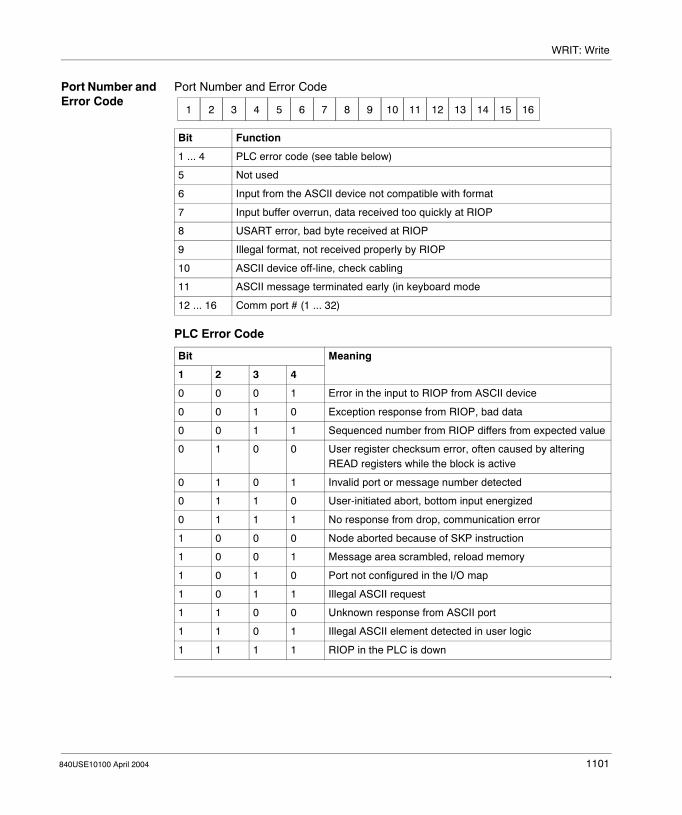
WRIT: Write
Port Number and Error Code
Port Number and Error Code
PLC Error Code
Bit Function
1 ... 4 PLC error code (see table below)
5 Not used
6 Input from the ASCII device not compatible with format
7 Input buffer overrun, data received too quickly at RIOP
8 USART error, bad byte received at RIOP
9 Illegal format, not received properly by RIOP
10 ASCII device off-line, check cabling
11 ASCII message terminated early (in keyboard mode
12 ... 16 Comm port # (1 ... 32)
Bit Meaning
1 2 3 4
0 0 0 1 Error in the input to RIOP from ASCII device
0 0 1 0 Exception response from RIOP, bad data
0 0 1 1 Sequenced number from RIOP differs from expected value
0 1 0 0 User register checksum error, often caused by altering READ registers while the block is active
0 1 0 1 Invalid port or message number detected
0 1 1 0 User-initiated abort, bottom input energized
0 1 1 1 No response from drop, communication error
1 0 0 0 Node aborted because of SKP instruction
1 0 0 1 Message area scrambled, reload memory
1 0 1 0 Port not configured in the I/O map
1 0 1 1 Illegal ASCII request
1 1 0 0 Unknown response from ASCII port
1 1 0 1 Illegal ASCII element detected in user logic
1 1 1 1 RIOP in the PLC is down
1 2 3 4 5 6 7 8 9 10 11 12 13 14 15 16
840USE10100 April 2004 1101

WRIT: Write
1102 840USE10100 April 2004

840USE10100 April 2004
176
XMIT - TransmitAt A Glance
Introduction This chapter describes the instruction XMIT - Transmit.
What's in this Chapter?
This chapter contains the following topics:
Topic Page
General Description: XMIT - Transmit 1104
XMIT Modbus Functions 1105
1103
XMIT - Transmit
General Description: XMIT - Transmit
Overview The XMIT (Transmit) function block sends Modbus messages from a "master" PLC to multiple slave PLCs or sends ASCII character strings from the PLC's Modbus slave port#1 or port#2 to ASCII printers and terminals. XMIT sends these messages over telephone dial up modems, radio modems, or simply direct connection.For more detailed information on the XMIT function block, see the section named XMIT Modbus Functions, p. 1105.XMIT comes with three modes: communication, port status, and conversion.These modes are described in the following sections.� XMIT Communication Block, p. 1111� XMIT Port Status Block, p. 1123� XMIT Conversion Block, p. 1131XMIT performs general ASCII input functions in the communication mode including simple ASCII and terminated ASCII. You may use an additional XMIT block for reporting port status information into registers while another XMIT block performs the ASCII communication function. You may import and export ASCII or binary data into your PLC and convert it into various binary data or ASCII to send to DCE devices based upon the needs of your application.The block has built in diagnostics, which ensure no other XMIT blocks are active in the PLC. Within the XMIT block a control table allows you to control the communications link between the PLC and Data Communication Equipment (DCE) devices attached to Modbus port #1 or port#2 of the PLC. The XMIT block does not activate the port LED when it's transmitting data.
Note: The Modbus protocol is a "master/slave" protocol and designed to have only one master when polling multiple slaves. Therefore, when using the XMIT block in a network with multiple masters, contention resolution, and collision avoidance is your responsibility and may easily be addressed through ladder logic programming.
1104 840USE10100 April 2004

XMIT - Transmit
XMIT Modbus Functions
At a Glance The XMIT function block supports the following Modbus function codes:.� 01 ... 06� 08� 15 and 16� 20 and 21For Modbus messages, the MSG_OUT array has to contain the Modbus definition table. The Modbus definition table for Modbus function code: 01, 02, 03, 04, 05, 06, 15 and 16 is five registers long and you must set XMIT_SET.MessageLen to 5 for successful XMIT operation. The Modbus definition table is shown in the table below
Modbus Function Codes 01...06
For Modbus messages, the MSG_OUT array has to contain the Modbus definition table. The Modbus definition table for Modbus function code: 01, 02, 03, 04, 05, 06, 15 and 16 is five registers long and you must set XMIT_SET.MessageLen to 5 for successful XMIT operation. The Modbus definition table is shown in the table below.Modbus Definition Table Function Codes (01 ... 06, 15 and 16)
Content Description
Modbus function code (MSG_OUT[1])
XMIT supports the following function codes: 01 = Read multiple coils (0x) 02 = Read multiple discrete inputs (1x) 03 = Read multiple holding registers (4x) 04= Read multiple input registers (3x) 05 = Write single coil (0x) 06 = Write single holding registers (4x) 15 = Write multiple coils (0x) 16 = Write multiple holding registers (4x)
Quantity (MSG_OUT[2])
Enter the amount of data you want written to the slave PLC or read from the slave PLC. For example, enter 100 to read 100 holding registers from the slave PLC or enter 32 to write 32 coils to a slave PLC. There is a size limitation on quantity that is dependent on the PLC model. Refer to Appendix A for complete details on limits.
Slave PLC address (MSG_OUT[3])
Enter the slave Modbus PLC address. Typically the Modbus address range is 1 ... 247. To send a Modbus message to multiple PLCs, enter 0 for the slave PLC address. This is referred to as Broadcast Mode. Broadcast Mode only supports Modbus function codes that writes data from the master PLC to slave PLCs. Broadcast Mode does NOT support Modbus function codes that read data from slave PLCs.
840USE10100 April 2004 1105

XMIT - Transmit
Source and Destination Data Areas for Function Codes (01 ... 06, 15 and 16)
When you want to send 20 Modbus messages out of the PLC, you must transfer 20 Modbus definition tables one after another into MSG_OUT after each successful operation of XMIT, or you may program 20 separate XMIT blocks and then activate them one at a time through user logic.
Slave PLC data area (MSG_OUT[4])
For a read command, the slave PLC data area is the source of the data. For a write command, the slave PLC data area is the destination for the data. For example, when you want to read coils (00300 ... 00500) from a slave PLC, enter 300 in this field. When you want to write data from a master PLC and place it into register (40100) of a slave PLC, enter 100 in this field. Depending on the type of Modbus command (write or read), the source and destination data areas must be as defined in the Source and Destination Data Areas table below.
Master PLC data area (MSG_OUT[5])
For a read command, the master PLC data area is the destination for the data returned by the slave. For a write command, the master PLC data area is the source of the data. For example, when you want to write coils (00016 ... 00032) located in the master PLC to a slave PLC, enter 16 in the field. When you want to read input registers (30001 ... 30100) from a slave PLC and place the data into the master PLC data area (40100 ... 40199), enter 100 in this field. Depending on the type of Modbus command (write or read), the source and destination data areas must be as defined in the Source and Destination Data Areas table below.
Function Code Master PLC Data Area Slave PLC Data Area
03 (Read multiple 4x) 4x (destination) 4x (source)
04 (Read multiple 3x) 4x (destination) 3x (source)
01 (Read multiple 0x) 0x (destination) 0x (source)
02 (Read multiple 1x) 0x (destination) 1x (source)
16 (Write multiple 4x) 4x (source) 4x (destination)
15 (Write multiple 0x) 0x (source) 0x (destination)
05 (Write single 0x) 0x (source) 0x (destination)
06 (Write single 4x) 4x (source) 4x (destination)
Content Description
1106 840USE10100 April 2004

XMIT - Transmit
Modbus Function Code (08)
The Modbus definition table for Modbus function code: 08 is five registers long and you must set XMIT_SET.MessageLen to 5. For Modbus messages, the MSG_OUT array has to contain the Modbus definition. The Modbus definition table is shown in the table below.Modbus Definition Table Function Codes (08)
Content Description
Modbus function code (MSG_OUT[1])
XMIT supports the following function code: 08 = Diagnostics
Diagnostics (MSG_OUT[2])
Enter the diagnostics subfunction code decimal value in this filed to perform the specific diagnostics function desired. The following diagnostic subfunctions are supported:
Code000102030405 ... 0910
11121314 ... 1516171819 ... 21
Description Return query dataRestart comm option Return diagnostic register Change ASCII input delimiter Force listen only mode Reserved Clear counters (& diagnostics registers in 384, 484) Return bus messages count Return bus comm error count Return bus exception error count Not supported Return slave NAK count Return slave busy count Return bus Char overrun count Not supported
Slave PLC address (MSG_OUT[3])
Enter the slave Modbus PLC address. Typically the Modbus address range is 1 ... 247. Function code 8 dose NOT support Broadcast Mode (Address 0)
Diagnostics function data field content (MSG_OUT[4])
You must enter the decimal value needed for the data area of the specific diagnostic subfunction. For subfunctions 02, 04, 10, 11, 12, 13, 16, 17 and 18 this value is automatically set to zero. For subfunctions 00, 01, and 03 you must enter the desired data field value. For more details, refer to Modicon Modbus Protocol Reference Guide (PI-MBUS-300).
Master PLC data area (MSG_OUT[5])
For all subfunctions, the master PLC data area is the destination for the data returned by the slave. You must specify a 4x register that marks the beginning of the data area where the returned data is placed. For example, to place the data into the master PLC data area starting at (40100), enter 100 in this field. Subfunction 04 does NOT return a response. For more details, refer to Modicon Modbus Protocol Reference Guide (PI-MBUS-300).
840USE10100 April 2004 1107

XMIT - Transmit
Modbus Function Codes (20, 21)
For Modbus messages, the MSG_OUT array has to contain the Modbus definition table. The Modbus definition table for Modbus function codes: 20 and 21 is six registers long and you must you must set XMIT_SET.MessageLen to 6 for successful XMIT operation. The Modbus definition table is shown in the table below.Modbus Definition Table Function Codes (20, 21)
Content Description
Modbus function code (MSG_OUT[1])
XMIT supports the following function codes: 20 = Read general reference (6x) 21 = Write general reference (6x)
Quantity (MSG_OUT[2])
Enter the amount of data you want written to the slave PLC or read from the slave PLC. For example, enter 100 to read 100 holding registers from the slave PLC or enter 32 to write 32 coils to a slave PLC. There is a size limitation on quantity that is dependent on the PLC model. Refer to Appendix A for complete details on limits.
Slave PLC address (MSG_OUT[3])
Enter the slave Modbus PLC address. Typically the Modbus address range is 1 ... 247. Function code 20 and 21 do NOT support Broadcast Mode (Address 0).
Slave PLC data area (MSG_OUT[4])
For a read command, the slave PLC data area is the source of the data. For a write command, the slave PLC data area is the destination for the data. For example, when you want to read registers (600300 ... 600399) from a slave PLC, enter 300 in this field. When you want to write data from a master PLC and place it into register (600100) of a slave PLC, enter 100 in this field. Depending on the type of Modbus command (write or read), the source and destination data areas must be as defined in the Source and Destination Data Areas table below. The lowest extended register is addressed as register "zero" (600000). The lowest holding register is addressed as register "one" (400001).
Master PLC data area (MSG_OUT[5])
For a read command, the master PLC data area is the destination for the data returned by the slave. For a write command, the master PLC data area is the source of the data. For example, when you want to write registers (40016 ... 40032) located in the master PLC to 6x registers in a slave PLC, enter 16 in the filed. When you want to read 6x registers (600001 ... 600100) from a slave PLC and place the data into the master PLC data area (40100 ... 40199), enter 100 in this field. Depending on the type of Modbus command (write or read), the source and destination data areas must be as defined in the Source and Destination Data Areas table below. The lowest extended register is addressed as register "zero" (600000). The lowest holding register is addressed as register "one" (400001).
File number (MSG_OUT[6])
Enter the file number for the 6x registers to be written to or read from. (1 ... 10) depending on the size of the extended register data area. 600001 is 60001 file 1 and 690001 is 60001 file 10 as viewed by the Reference Data Editor.
1108 840USE10100 April 2004

XMIT - Transmit
Source and Destination Data Areas for Function Codes (20, 21)
When you want to send 20 Modbus messages out of the PLC, you must transfer 20 Modbus definition tables one after another into MSG_OUT after each successful operation of XMIT, or you may program 20 separate XMIT blocks and then activate them one at a time through user logic.
Function Code Master PLC Data Area Slave PLC Data Area
20 (Read general reference 6x)
4x (destination) 6x (source)
21 (Write general reference 6x)
4x (source) 6x (destination)
840USE10100 April 2004 1109

XMIT - Transmit
1110 840USE10100 April 2004

840USE10100 April 2004
177
XMIT Communication BlockAt A Glance
Introduction This chapter describes the instruction XMIT Communication Block.
What's in this Chapter?
This chapter contains the following topics:
Topic Page
Short Description: XMIT Communication Block 1112
Representation: XMIT Communication Block 1113
Parameter Description: Middle Node - Communication Control Table 1115
Parameter Description: XMIT Communication Block 1119
Parameter Description: XMIT Communications Block 1121
1111

XMIT Communication Block
Short Description: XMIT Communication Block
Function Description
The purpose of the XMIT communication block is to receive and transmit ASCII messages and Modbus Master messages using your PLC ports.The XMIT instruction block will not operate correctly if:� The NSUP and XMIT loadables are not installed� The NSUP loadable is installed after the XMIT loadable� The NSUP and XMIT loadables are installed in a Quantum PLC with an out-of-
date executive (older than version 2.10 or 2.12)For an overview of the XMIT instruction please see General Description: XMIT - Transmit, p. 1104.
1112 840USE10100 April 2004

XMIT Communication Block
Representation: XMIT Communication Block
Symbol Representation of the instruction
START
ABORT
OPERATION IS ACTIVE
OPERATION TERMINATEDUNSUCCESSFULLY
OPERATION SUCCESSFUL
port#0001
or#0002
register
XMIT
constant =#0016
840USE10100 April 2004 1113

XMIT Communication Block
Parameter Description
Description of the instruction’s parameters
Parameters State RAM Reference
Data Type
Meaning
Top input 0x, 1x None ON begins an XMIT operation and START should remain ON until the operation has completed successfully or an error has occurred.
Middle input 0x, 1x None ON aborts any active XMIT operation and forces the port to slave mode. The abort code (121) is placed into the fault status register. The port remains closed as long as this input is ON.Note: To reset an XMIT fault and clear the fault register, the top input must go OFF for at least one PLC scan.
port #0001 or #0002(top node)
4x INT, UINT, WORD
The top node must contain one of the following constants either (#0001) to select PLC port #1, or (#0002) to select PLC port #2.Note: The loadable version DOES accept 4xxxx registers in the top node, whereas the built-in does NOT.
register(middle node)
4x INT, UINT, WORD
The 4xxxx register entered in the middle node is the first in a group of sixteen (16) contiguous holding registers that comprise the control block, as shown in the Communication Control Table.(For expanded and detailed information on this node please see the Communication Control Table, p. 1115 in the Parameter Description: Middle Node - XMIT Communication Block.)Important: DO NOT modify the address in the middle node of the XMIT block or delete the address from the block while the program is active. This action locks up the port preventing communications.
#0016(bottom node)
INT, UINT, WORD
The bottom node must contain a constant equal to (#0016). This is the number of registers used by the XMIT instruction.
Top output 0x None ON while an XMIT operation in progress.Passes power while an XMIT operation is in progress.
Middle output
0x None ON when XMIT has detected an error or was issued an abort.Passes power when XMIT has detected an error or when an XMIT operation was aborted.
Bottom output
0x None ON for one scan only when an XMIT operation has been successfully completed.Passes power when an XMIT operation has been successfully completed.Note: The START input must remain ON until the OPERATION SUCCESSFUL has turned OFF.
1114 840USE10100 April 2004

XMIT Communication Block
Parameter Description: Middle Node - Communication Control Table
Communication Control Table
This table represents the first in a group of 16 contiguous holding registers that comprise the control block.
Register Name Description No Valid Entries
4xxxx Revision Number
Displays the current revision number of XMIT block.This number is automatically loaded by the block and the block over writes any other number entered into this register.
Read Only
4xxxx + 1 Fault Status This field displays a fault code generated by the XMIT port status block.(For expanded and detailed information please see the Fault Status Table, p. 1119 in the Parameter Description: XMIT Communication Block section).
Read Only
4xxxx + 2 Available to User
The XMIT block does not use this register. However, it may be used in ladder logic as a pointer. An efficient way to use the XMIT block is to place a pointer value of a TBLK instruction into this register.
Read/Write
4xxxx + 3 Data Rate XMIT supports the following data rates: 50, 75, 110, 134, 150, 300, 600, 1200, 1800, 2000, 2400, 3600, 4800, 7200, 9600 and 19200.To configure a data rate, enter its decimal number into this field. When an invalid data rate is entered, the block displays an illegal configuration error (error code 127) in the Fault Status (4xxxx + 1) register.
Read/Write
4xxxx + 4 Data Bits XMIT supports the following data bits: 7 and 8.To configure a data bit size, enter its decimal number into this register.Note: Modbus messages may be sent in ASCII mode or RTU mode. ASCII mode requires 7 data bits, while RTU mode requires 8 data bits. When sending ASCII character message you may use either 7 or 8 data bits. When an invalid data bit is entered, the block displays an illegal configuration error (error code 127) in the Fault Status (4xxxx + 1) register.
Read/Write
840USE10100 April 2004 1115

XMIT Communication Block
4xxxx + 5 Parity Bits XMIT supports the following parity: none, odd and even. Enter a decimal of either: 0 = no parity, 1 = odd parity, or 2 = even parity. When an invalid parity is entered, the block displays an illegal configuration error (error code 127) in the Fault Status (4xxxx + 1) register.
Read/Write
4xxxx + 6 Stop Bits XMIT supports one or two stop bits. Enter a decimal of either: 1 = one stop bit, or 2 = two stop bits. When an invalid stop bit is entered, the block displays an illegal configuration error (error code 127) in the Fault Status (4xxxx + 1) register.
Read/Write
4xxxx + 7 Available to User
The XMIT block does not use this register. However, it may be used in ladder logic as a pointer. An efficient way to use the XMIT block is to place a pointer value of a TBLK instruction into this register.
Read/Write
4xxxx + 8 Command Word
(16-digit binary number)The XMIT interprets each bit of the command word as a function to perform. If bit 7 and 8 are on simultaneously or if any two or more of bits 13, 14, 15 or 16 are on simultaneously or if bit 7 is not on when bits 13, 14, 15, or 16 are on error 129 will be generated.For expanded and detailed information please see the Command Word Communication Functions Table, p. 1121 in the Parameter Description: XMIT Communications Block section.
Read/Write
Register Name Description No Valid Entries
1116 840USE10100 April 2004

XMIT Communication Block
4xxxx + 9 Message Pointer Word
(message pointer)Values are limited by the range of 4x registers configured.The message table consists of either� ASCII characters
For ASCII character strings, the pointer is the register offset to the first register of the ASCII character string. Each register holds up to two ASCII characters. Each ASCII string may be up to 1024 characters in length. For example, when you want to send 10 ASCII messages out of the PLC, you must program 10 ASCII characters strings into 4xxxx registers of the PLC and then through ladder logic set the pointer to the start of each message after each successful operation of XMIT.
� Modbus Function CodesFor expanded and detailed information please see the section XMIT Modbus Functions, p. 1105
Enter a pointer that points to the beginning of the message table.
Read/Write
4xxxx + 10 Message Length
(0 - 512)Enter the length of the current message. When XMIT is sending Modbus messages for function codes 01, 02, 03, 04, 05, 06, 08, 15 and 16, the length of the message is automatically set to five. When XMIT is receiving Terminated ASCII input the length of the message must be set to five or an error results. When XMIT is sending Modbus messages for function codes twenty and twenty- -one, the length of the message is automatically set to six. When XMIT is sending ASCII messages, the length may be 1 through 1024 ASCII characters per message.
Read/Write
4xxxx + 11 Response Timeout (ms)
(0 - 65535 milliseconds)Enter the time value in milliseconds (ms) to determine how long XMIT waits for a valid response message from a slave device (PLC, modem, etc.). In addition, the time applies to ASCII transmissions and flow control operations. When the response message is not completely formed within this specified time, XMIT issues a fault. The valid range is 0 through 65535 ms. The timeout is initiated after the last character in the message is sent.
Read/Write
Register Name Description No Valid Entries
840USE10100 April 2004 1117

XMIT Communication Block
4xxxx + 12 Retry Limit (0 - 65535 milliseconds)Enter the quantity of retries to determine how many times XMIT sends a message to get a valid response from a slave device (PLC, modem, etc.). When the response message is not completely formed within this specified time, XMIT issues a fault and a fault code. The valid range is 0 ... 65535 # of retries. This field is used in conjunction with response time-out (4xxxx + 11).
Read/Write
4xxxx + 13 Start of Transmission Delay (ms)
(0 - 65535 milliseconds)Enter the time value in milliseconds (ms) when RTS/CTS control is enabled, to determine how long XMIT waits after CTS is received before it transmits a message out of the PLC port #1. Also, you may use this register even when RTS/CTS is NOT in control. In this situation, the entered time value determines how long XMIT waits before it sends a message out of the PLC port #1. You may use this as a pre message delay timer. The valid range is 0 through 65535 ms.
Read/Write
4xxxx + 14 End of Transmission Delay (ms)
(0 - 65535 milliseconds)To determine how long XMIT keeps an RTS assertion once the message is sent out of the PLC port #1, enter the time value in milliseconds (ms) when RTS/CTS control is enabled, After the time expires, XMIT ends the RTS assertion. Also, you may use this register even when RTS/CTS is NOT in control. In this situation, the entered time value determines how long XMIT waits after it sends a message out of the PLC port #1. You may use this as a post message delay timer. The valid range is 0 through 65535 ms.
Read/Write
4xxxx + 15 Current Retry The value displayed here indicates the current number of retry attempts made by the XMIT block
Read Only
Register Name Description No Valid Entries
1118 840USE10100 April 2004

XMIT Communication Block
Parameter Description: XMIT Communication Block
Fault Status Table
The following is a list of the fault codes generated by the XMIT port status block (4x + 1).
Fault Code Fault Description
1 Modbus exception -- Illegal function
2 Modbus exception -- Illegal data address
3 Modbus exception -- Illegal data value
4 Modbus exception -- Slave device failure
5 Modbus exception -- Acknowledge
6 Modbus exception -- Slave device busy
7 Modbus exception -- Negative acknowledge
8 Modbus exception -- Memory parity error
9 through 99 Reserved
100 Slave PLC data area cannot equal zero
101 Master PLC data area cannot equal zero
102 Coil (0x) not configured
103 Holding register (4xxxx) not configured
104 Data length cannot equal zero
105 Pointer to message table cannot equal zero
106 Pointer to message table is outside the range of configured holding registers (4xxxx)
107 Transmit message timeout(This error is generated when the UART cannot complete a transmission in 10 seconds or less. This error bypasses the retry counter and will activate the error output on the first error.)
108 Undefined error
109 Modem returned ERROR
110 Modem returned NO CARRIER
111 Modem returned NO DIALTONE
112 Modem returned BUSY
113 Invalid LRC checksum from the slave PLC
114 Invalid CRC checksum from the slave PLC
115 Invalid Modbus function code
116 Modbus response message time-out
117 Modem reply timeout
840USE10100 April 2004 1119

XMIT Communication Block
118 XMIT could not gain access to PLC communications port #1 or port #2
119 XMIT could not enable PLC port receiver
120 XMIT could not set PLC UART
121 User issued an abort command
122 Top node of XMIT not equal to zero, one or two
123 Bottom node of XMIT is not equal to seven, eight or sixteen
124 Undefined internal state
125 Broadcast mode not allowed with this Modbus function code
126 DCE did not assert CTS
127 Illegal configuration (data rate, data bits, parity, or stop bits)
128 Unexpected response received from Modbus slave
129 Illegal command word setting
130 Command word changed while active
131 Invalid character count
132 Invalid register block
133 ASCII input FIFO overflow error
134 Invalid number of start characters or termination characters
Fault Code Fault Description
1120 840USE10100 April 2004

XMIT Communication Block
Parameter Description: XMIT Communications Block
Command Word Communication Functions Table
This table describes the function performed as XMIT interprets each bit of the command word.
(4x + 8) Command Word Function Command word bits that must be set to 1
Command word bits that must be set to 0
Terminated ASCII input (Bit 5=1) 2,3,9,10,11,12 6,7,8,13,14,15,16
Simple ASCII input (Bit 6=1) 2,3,9,10,11,12 5,7,8,13,14,15,16
Simple ASCII output (Bit 7=1) 2,3,9,10,11,12 5,6,8,13,14,15,16
Modem output (Bit 7=1) 2,3,13,14,15,16 5,6,8,9,10,11,12(plus one, but ONLY one, of the following bits is set to 1: 13,14,15 or 16, while the other three bits must be set to 0)
Modbus master messaging output(Bit 8=1)
2,3 5,6,7,9,10,11,12,13,14,15,16
Enable ASCII receive input FIFO ONLY (Bit 9=1)
2,3,10,11,12 5,6,7,8,13,14,15,16
840USE10100 April 2004 1121

XMIT Communication Block
1122 840USE10100 April 2004
840USE10100 April 2004
178
XMIT Port Status BlockAt A Glance
Introduction This chapter describes the instruction XMIT Port Status Block.
What's in this Chapter?
This chapter contains the following topics:
Topic Page
Short Description: XMIT Port Status Block 1124
Representation: XMIT Port Status Block 1125
Parameter Description: Middle Node - XMIT Conversion Block 1127
1123

XMIT Port Status Block
Short Description: XMIT Port Status Block
Function Description
The XMIT port status block shows the current port status, Modbus slave activity, ASCII input FIFO and flow control information that may be used in ladder logic for some applications. The XMIT port status block is totally passive. It does not take, release, or control the PLC port.For an overview of the XMIT instruction please see General Description: XMIT - Transmit, p. 1104.
1124 840USE10100 April 2004

XMIT Port Status Block
Representation: XMIT Port Status Block
Symbol Representation of the instruction
START
OPERATION TERMINATEDUNSUCCESSFULLY
OPERTION SUCCESSFUL
port#0001
or#0002
register
XMIT
constant =#0007
840USE10100 April 2004 1125
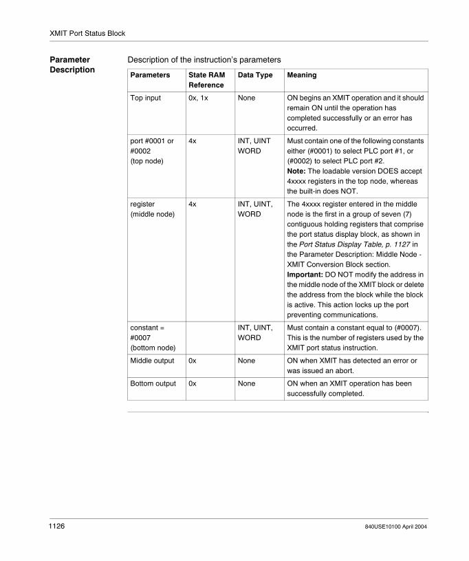
XMIT Port Status Block
Parameter Description
Description of the instruction’s parameters
Parameters State RAM Reference
Data Type Meaning
Top input 0x, 1x None ON begins an XMIT operation and it should remain ON until the operation has completed successfully or an error has occurred.
port #0001 or #0002(top node)
4x INT, UINT WORD
Must contain one of the following constants either (#0001) to select PLC port #1, or (#0002) to select PLC port #2.Note: The loadable version DOES accept 4xxxx registers in the top node, whereas the built-in does NOT.
register(middle node)
4x INT, UINT, WORD
The 4xxxx register entered in the middle node is the first in a group of seven (7) contiguous holding registers that comprise the port status display block, as shown in the Port Status Display Table, p. 1127 in the Parameter Description: Middle Node - XMIT Conversion Block section.Important: DO NOT modify the address in the middle node of the XMIT block or delete the address from the block while the block is active. This action locks up the port preventing communications.
constant = #0007(bottom node)
INT, UINT, WORD
Must contain a constant equal to (#0007). This is the number of registers used by the XMIT port status instruction.
Middle output 0x None ON when XMIT has detected an error or was issued an abort.
Bottom output 0x None ON when an XMIT operation has been successfully completed.
1126 840USE10100 April 2004
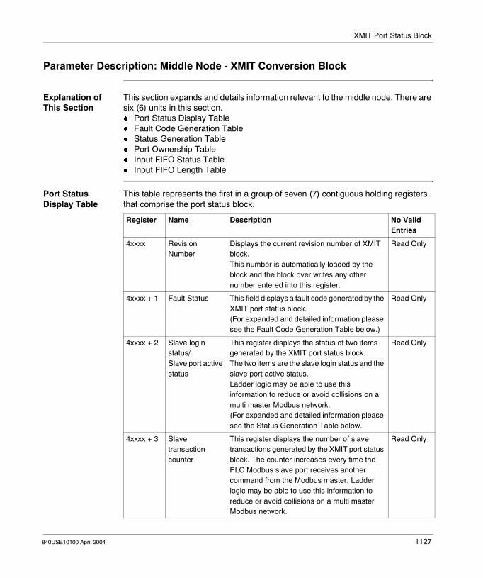
XMIT Port Status Block
Parameter Description: Middle Node - XMIT Conversion Block
Explanation of This Section
This section expands and details information relevant to the middle node. There are six (6) units in this section.� Port Status Display Table� Fault Code Generation Table� Status Generation Table� Port Ownership Table� Input FIFO Status Table� Input FIFO Length Table
Port Status Display Table
This table represents the first in a group of seven (7) contiguous holding registers that comprise the port status block.
Register Name Description No Valid Entries
4xxxx Revision Number
Displays the current revision number of XMIT block.This number is automatically loaded by the block and the block over writes any other number entered into this register.
Read Only
4xxxx + 1 Fault Status This field displays a fault code generated by the XMIT port status block.(For expanded and detailed information please see the Fault Code Generation Table below.)
Read Only
4xxxx + 2 Slave login status/Slave port active status
This register displays the status of two items generated by the XMIT port status block.The two items are the slave login status and the slave port active status.Ladder logic may be able to use this information to reduce or avoid collisions on a multi master Modbus network.(For expanded and detailed information please see the Status Generation Table below.
Read Only
4xxxx + 3 Slave transaction counter
This register displays the number of slave transactions generated by the XMIT port status block. The counter increases every time the PLC Modbus slave port receives another command from the Modbus master. Ladder logic may be able to use this information to reduce or avoid collisions on a multi master Modbus network.
Read Only
840USE10100 April 2004 1127
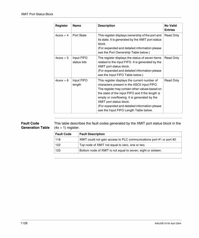
XMIT Port Status Block
Fault Code Generation Table
This table describes the fault codes generated by the XMIT port status block in the (4x + 1) register.
4xxxx + 4 Port State This register displays ownership of the port and its state. It is generated by the XMIT port status block.(For expanded and detailed information please see the Port Ownership Table below.)
Read Only
4xxxx + 5 Input FIFO status bits
The register displays the status of seven items related to the input FIFO. It is generated by the XMIT port status block.(For expanded and detailed information please see the Input FIFO Table below.)
Read Only
4xxxx + 6 Input FIFO length
This register displays the current number of characters present in the ASCII input FIFO. The register may contain other values based on the state of the input FIFO and if the length is empty or overflowing. It is generated by the XMIT port status block.(For expanded and detailed information please see the Input FIFO Length Table below.
Read Only
Register Name Description No Valid Entries
Fault Code Fault Description
118 XMIT could not gain access to PLC communications port #1 or port #2.
122 Top node of XMIT not equal to zero, one or two.
123 Bottom node of XMIT is not equal to seven, eight or sixteen.
1128 840USE10100 April 2004

XMIT Port Status Block
Status Generation Table
This table describes the slave login status and the slave port active status generated by the XMIT port status block for the (4x + 2) register.
Port Ownership Table
This table describes the port’s ownership and state for the (4x + 4) register.
(4x + 2 high byte)Slave Login Status
(4x + 2 low byte)Slave Port Active Status
Yes - When a programming device is currently logged ON to this PLC slave port.
Yes - When observed port is owned by the PLC and currently receiving a Mod-bus command or transmitting a Mod-bus response.
No - When a programming device is currently NOT logged ON to this PLC slave port.Note: A Modbus master can send commands but, not be logged ON
No - When observed port is NOT owned by the PLC and currently receiving Mod-bus command or transmitting a Mod-bus response.
Owns Port Active State Value
PLC PLC Modbus slave 0
XMIT Tone dial modem 1
XMIT Hang up modem 2
XMIT Modbus messaging 3
XMIT Simple ASCII output 4
XMIT Pulse dial modem 5
XMIT Initialize modem 6
XMIT Simple ASCII input 7
XMIT Terminated ASCII input 8
XMIT ASCII input FIFO is ON, but no XMIT function is active 9
840USE10100 April 2004 1129

XMIT Port Status Block
Input FIFO Status Table
This table describes the status bits related to the input FIFO for the (4x + 5) register.
Input FIFO Length Table
This table describes the current number of characters present in the ASCII input FIFO for the (4x + 6) register.
Bit # Definition Yes / 1 No / 0
1 - 3 Reserved
4 Port owned by ... XMIT PLC
5 - 7 Reserved
8 ASCII output transmission ... Blocked by receiving device
Unblocked by receiving device
9 ASCII input received ... New character No new character
10 ASCII input FIFO is ... Empty Not empty
11 ASCII input FIFO is ... Overflowing (error) Not overflowing (error)
12 ASCII input FIFO is ... On Off
13 - 15 Reserved
16 ASCII input reception ... XMIT blocked sending device
XMIT unblocked sending device
WHEN Input FIFO THEN Length
= OFF = 0
= ON and Empty = 0
= ON and Overflowing = 512
1130 840USE10100 April 2004

840USE10100 April 2004
179
XMIT Conversion BlockAt A Glance
Introduction This chapter describes the instruction XMIT Conversion Block.
What's in this Chapter?
This chapter contains the following topics:
Topic Page
Short Description: XMIT Conversion Block 1132
Representation: XMIT Conversion Block 1133
Parameter Description: XMIT Conversion Block 1135
1131
XMIT Conversion Block
Short Description: XMIT Conversion Block
Function Description
The purpose of the XMIT conversion block is to take data and convert it into other usable forms based upon your application needs. The convert block performs eleven (11) different functions or options. Some functions include ASCII to binary, integer to ASCII, byte swapping, searching ASCII strings, and others. This block allows internal conversions using 4xxxx source blocks to 4xxxx destination blocks.For an overview of the XMIT instruction please see General Description: XMIT - Transmit, p. 1104.
1132 840USE10100 April 2004

XMIT Conversion Block
Representation: XMIT Conversion Block
Symbol Representation of the instruction
START
OPERATION TERMINATEDUNSUCCESSFULLY
OPERTION SUCCESSFUL
constant#0001
register
XMIT
constant =#0008
840USE10100 April 2004 1133

XMIT Conversion Block
Parameter Description
Description of the instruction’s parameters
Parameters State RAM Reference
Data Type Meaning
Top input 0x, 1x None ON begins an XMIT operation and it should remain ON until the operation has completed successfully or an error has occurred.Note: To reset an XMIT fault and clear the fault register, the top input must go OFF for at least one PLC scan.
constant #0001(top node)
4x INT, UINT WORD
The top node must contain a constant (#0000) since conversions do not deal with the PLC’s port.The loadable version DOES accept 4xxxx registers in the top node, whereas the built-in does NOT.
register(middle node)
4x INT, UINT, WORD
The 4xxxx register entered in the middle node is the first in a group of eight (8) contiguous holding registers that comprise the control block, as shown in the Conversion Block Control Table, p. 1135 found in the Parameter Description: XMIT Conversion Block section.Important: DO NOT modify the address in the middle node of the XMIT block or delete the address from the program while the block is active. This action locks up the port preventing communications.
constant = #0008(bottom node)
INT, UINT, WORD
The bottom node must contain a constant equal to (#0008). This is the number of registers used by the XMIT conversion instruction.
Middle output 0x None ON when XMIT has detected an error or was issued an abort.
Bottom output 0x None ON when an XMIT operation has been successfully completed.
1134 840USE10100 April 2004

XMIT Conversion Block
Parameter Description: XMIT Conversion Block
Explanation of This Section
This section expands and details information relevant to the middle node. There are four (4) units in this section.� Conversion Block Control Table� Fault Code Generation Table� Data Conversion Control Bits Table� Data Conversion Opcodes Table
Conversion Block Control Table
This table represents the first in a group of eight (8) contiguous holding registers that comprise the port status block.
Register Name Description No Valid Entries
4xxxx XMIT Revision Number
Displays the current revision number of XMIT block.This number is automatically loaded by the block and the block over writes any other number entered into this register.
Read Only
4xxxx + 1 Fault Status This field displays a fault code generated by the XMIT port status block.(For expanded and detailed information please see the Fault Code Generation Table below.)
Read Only
4xxxx + 2 Available to User
0 (May be used as pointers for instructions such as TBLK.)The XMIT conversion block does not use this register. However, it may be used in ladder logic as a pointer. An efficient way to use the XMIT block is to place a pointer value of a TBLK instruction into this register.
Read/Write
4xxxx + 3 Data Conversion Control Bits
This 16 bit word relates to the Data Conversion (4xxxx + 3) word. These bits provide additional control options based on which of the eleven conversions you select.(For expanded and detailed information please see Data Conversion Control Bits Table below.
Read/Write
840USE10100 April 2004 1135

XMIT Conversion Block
4xxxx + 4 Data Conversion Opcodes
Select the type of conversion you want to perform from the list of eleven options listed in the Data Conversion Opcodes Table below.After picking the type of conversion refer to Data Conversion Control Bits (4xxxx + 4) and the Data Conversion Control Bits Table for additional control options that relate to the specific conversion type selected.
Read/Write
4xxxx + 5 Source Register
Enter the 4xxxx register desired.This is the first register in the source block that is read. Ensure you select where you want the READ to begin (high or low byte).
Read/Write
4xxxx + 6 Destination Register
Enter the 4xxxx register desired.This is the first register in the source block that is read. Ensure you select where you want the READ to begin (high or low byte).The selection beside this register in the DX zoom is the same as bit16 in (4xxxx + 3).
Read/Write
4xxxx + 7 ASCII String Character Count
Enter the search area. This register defines the search area.When either automatic advance source (Bit 13) or automatic advance destination (Bit 14) are ON and no ASCII character is detected, the block automatically adjusts the character count.
Read/Write
Register Name Description No Valid Entries
1136 840USE10100 April 2004
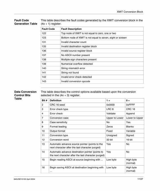
XMIT Conversion Block
Fault Code Generation Table
This table describes the fault codes generated by the XMIT conversion block in the (4x + 1) register.
Data Conversion Control Bits Table
This table describes the control options available based upon the conversion selected in the (4x + 3) register.
Fault Code Fault Description
122 Top node of XMIT is not equal to zero, one or two
123 Bottom node of XMIT is not equal to seven, eight or sixteen
131 Invalid character count
135 Invalid destination register block
136 Invalid source register block
137 No ASCII number present
138 Multiple sign characters present
139 Numerical overflow detected
140 String mismatch error
141 String not found
142 Invalid error check detected
143 Invalid conversion opcode
Bit # Definition 1 = 0 =
2 CRC 16 seed 0x0000 0xFFFF
3 Error check type LRC 8 CRC 16
4 Error check Validate Append
7 Conversion case Upper to Lower Lower to Upper
8 Case sensitivity No Yes
9 Format leading Zeros Blanks
10 Output format Fixed Variable
11 Conversion type Unsigned Signed
12 Conversion word 32-bit 16-bit
13 Automatic advance source pointer (points to the next character after the last character purged)
Yes No
14 Automatic advance destination pointer (points to the next character after the last character purged)
Yes No
15 Begin reading ASCII at source beginning with ... Low byte High byte (normal)
16 Begin saving ASCII at destination beginning with ...
Low byte High byte (normal)
840USE10100 April 2004 1137

XMIT Conversion Block
Data Conversion Opcodes Table
This table describes the eleven (11) functions or options for performing conversions using the data conversion opcodes in the (4x + 4) register.
Opcode Action Data Type(4xxxx block
Illegal opcode Displayed when illegal opcode is detected.
Not applicable
(1 Hex)Received ASCII decimal character string
Converted to 16-bit or 32-bit signed or unsigned binary integer
(2 Hex)Received ASCII hex character string
Converted to 16-bit or 32-bit unsigned binary integer
(3 Hex)Received ASCII hex character string
Converted to 16-bit unsigned binary integer array
(4 Hex)16-bit or 32-bit signed or unsigned integer
Converted to ASCII decimal character string for transmission
(5 Hex)16-bit or 32-bit unsigned binary integer
Converted to ASCII hex character string for transmission
(6 Hex)16-bit unsigned integer array
Converted to ASCII hex character string for transmission
(7 Hex)High and low bytes from saved ASCII source register block
Swapped to ASCII destination register block
(8 Hex)ASCII string from source register block
Copied to ASCII destination register block with or without case conversion
(9 Hex)ASCII source register block
Compared to ASCII string defined in destination register block with or without case sensitivity
(10 Hex)ASCII source register block
Search for ASCII string defined in destination block with or without case sensitivity
(11 Hex)Error check 8-bit LRC or 16-bit CRC
Validated or Appended on
ASCII string in source register block
1138 840USE10100 April 2004

840USE10100 April 2004
180
XMRD: Extended Memory ReadAt a Glance
Introduction This chapter describes the instruction XMRD.
What's in this Chapter?
This chapter contains the following topics:
Topic Page
Short Description 1140
Representation: XMRD - Extended Memory Read 1141
Parameter Description 1142
1139

XMRD: Extended Memory Read
Short Description
Function Description
The XMRD instruction is used to copy a table of 6x extended memory registers to a table of 4x holding registers in state RAM.
1140 840USE10100 April 2004
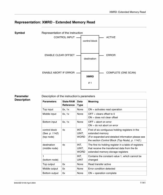
XMRD: Extended Memory Read
Representation: XMRD - Extended Memory Read
Symbol Representation of the instruction
Parameter Description
Description of the instruction’s parameters
CONTROL INPUT
ENABLE CLEAR OFFSET
ENABLE ABORT IF ERROR
ACTIVE
ERROR
COMPLETE (ONE SCAN)
control block
destination
XMRD
# 1
Parameters State RAM Reference
Data Type
Meaning
Top input 0x, 1x None ON = activates read operation
Middle input 0x, 1x None OFF = clears offset to 0ON = does not clear offset
Bottom input 0x, 1x None OFF = abort on errorON = do not abort on error
control block (See p. 1142)(top node)
4x INT, UINT, WORD
First of six contiguous holding registers in the extended memory(For expanded and detailed information please see the section Control Block (Top Node), p. 1142.)
destination(middle node)
4x INT, UINT, WORD
The first 4x holding register in a table of registers that receive the transferred data from the 6x extended memory storage registers
1(bottom node)
INT, UINT
Contains the constant value 1, which cannot be changed
Top output 0x None Read transfer active
Middle output 0x None Error condition detected
Bottom output 0x None ON = operation complete
840USE10100 April 2004 1141

XMRD: Extended Memory Read
Parameter Description
Control Block (Top Node)
The 4x register entered in the top node is the first of six contiguous holding registers in the extended memory control block.
If you are in multi-scan mode, these six registers should be unique to this function block.
Reference Register Name Description
Displayed status word Contains the diagnostic information about extended memory (see Status Word of the Control Block, p. 1143)
First implied file number Specifies which of the extended memory files is currently in use (range: 1 ... 10)
Second implied
start address Specifies which 6x storage register in the current file is the starting address; 0 = 60000, 9999 = 69999
Third implied count Specifies the number of registers to be read or written in a scan when the appropriate function block is powered; range: 0 ... 9999, not to exceed number specified in max registers (fifth implied)
Fourth implied offset Keeps a running total of the number of registers transferred thus far
Fifth implied max registers Specifies the maximum number of registers that may be transferred when the function block is powered (range: 0 ... 9999)
1142 840USE10100 April 2004

XMRD: Extended Memory Read
Status Word of the Control Block
Status Word of the Control Block
Bit Function
1 1 = power-up diagnostic error
2 1 = parity error in extended memory
3 1 = extended memory does not exist
4 0 = transfer not running1 = busy
5 0 = transfer in progress1 = transfer complete
6 1 = file boundary crossed
7 1 = offset parameter too large
8 - 9 Not used
10 1 = nonexistent state RAM
11 Not used
12 1 = maximum registers parameter error
13 1 = offset parameter error
14 1 = count parameter error
15 1 = starting address parameter error
16 1 = file number parameter error
1 2 3 4 5 6 7 8 9 10 11 12 13 14 15 16
840USE10100 April 2004 1143

XMRD: Extended Memory Read
1144 840USE10100 April 2004

840USE10100 April 2004
181
XMWT: Extended Memory WriteAt a Glance
Introduction This chapter describes the instruction XMWT.
What's in this Chapter?
This chapter contains the following topics:
Topic Page
Short Description 1146
Representation: XMWT - Extended Memory Write 1147
Parameter Description 1148
1145

XMWT: Extended Memory Write
Short Description
Function Description
The XMWT instruction is used to write data from a block of input registers or holding registers in state RAM to a block of 6x registers in an extended memory file.
1146 840USE10100 April 2004
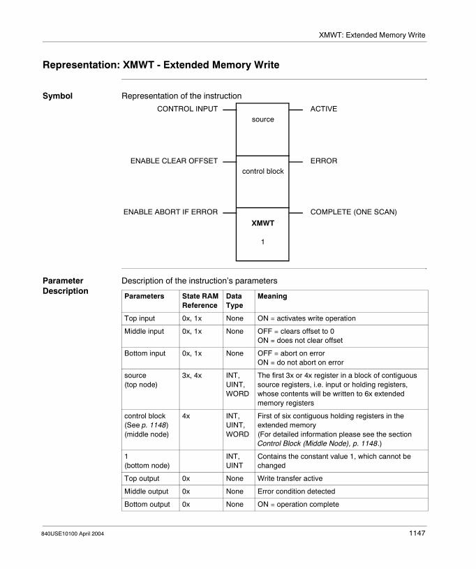
XMWT: Extended Memory Write
Representation: XMWT - Extended Memory Write
Symbol Representation of the instruction
Parameter Description
Description of the instruction’s parameters
CONTROL INPUT
ENABLE CLEAR OFFSET
ENABLE ABORT IF ERROR
ACTIVE
ERROR
COMPLETE (ONE SCAN)
source
control block
XMWT
1
Parameters State RAM Reference
Data Type
Meaning
Top input 0x, 1x None ON = activates write operation
Middle input 0x, 1x None OFF = clears offset to 0ON = does not clear offset
Bottom input 0x, 1x None OFF = abort on errorON = do not abort on error
source(top node)
3x, 4x INT, UINT, WORD
The first 3x or 4x register in a block of contiguous source registers, i.e. input or holding registers, whose contents will be written to 6x extended memory registers
control block (See p. 1148)(middle node)
4x INT, UINT, WORD
First of six contiguous holding registers in the extended memory(For detailed information please see the section Control Block (Middle Node), p. 1148.)
1(bottom node)
INT, UINT
Contains the constant value 1, which cannot be changed
Top output 0x None Write transfer active
Middle output 0x None Error condition detected
Bottom output 0x None ON = operation complete
840USE10100 April 2004 1147

XMWT: Extended Memory Write
Parameter Description
Control Block (Middle Node)
The 4x register entered in the middle node is the first of six contiguous holding registers in the extended memory control block.
If you are in multi-scan mode, these six registers should be unique to this function block.
Reference Register Name Description
Displayed status word Contains the diagnostic information about extended memory (see Status Word of the Control Block, p. 1149)
First implied file number Specifies which of the extended memory files is currently in use (range: 1 ... 10)
Second implied
start address Specifies which 6x storage register in the current file is the starting address; 0 = 60000, 9999 = 69999
Third implied count Specifies the number of registers to be read or written in a scan when the appropriate function block is powered; range: 0 ... 9999, not to exceed number specified in max registers (fifth implied)
Fourth implied offset Keeps a running total of the number of registers transferred thus far
Fifth implied max registers Specifies the maximum number of registers that may be transferred when the function block is powered (range: 0 ... 9999)
1148 840USE10100 April 2004
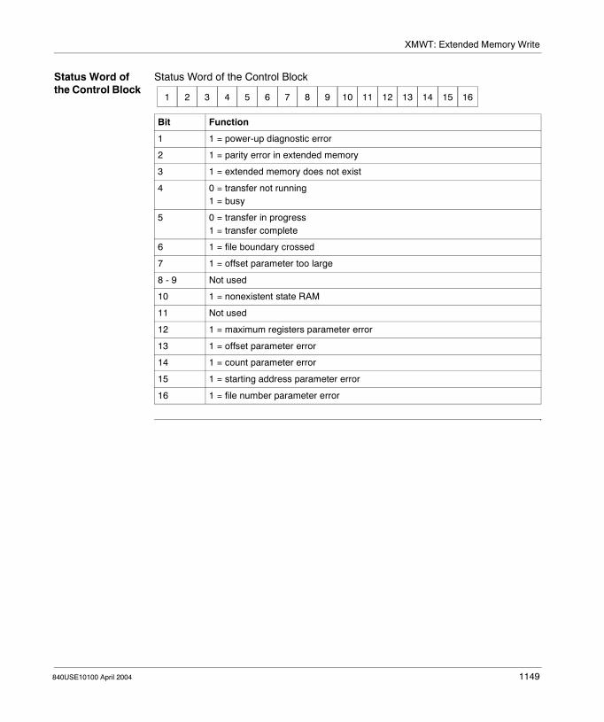
XMWT: Extended Memory Write
Status Word of the Control Block
Status Word of the Control Block
Bit Function
1 1 = power-up diagnostic error
2 1 = parity error in extended memory
3 1 = extended memory does not exist
4 0 = transfer not running1 = busy
5 0 = transfer in progress1 = transfer complete
6 1 = file boundary crossed
7 1 = offset parameter too large
8 - 9 Not used
10 1 = nonexistent state RAM
11 Not used
12 1 = maximum registers parameter error
13 1 = offset parameter error
14 1 = count parameter error
15 1 = starting address parameter error
16 1 = file number parameter error
1 2 3 4 5 6 7 8 9 10 11 12 13 14 15 16
840USE10100 April 2004 1149

XMWT: Extended Memory Write
1150 840USE10100 April 2004

840USE10100 April 2004
182
XOR: Exclusive ORAt a Glance
Introduction This chapter describes the instruction XOR.
What's in this Chapter?
This chapter contains the following topics:
Topic Page
Short Description 1152
Representation: XOR - Boolean Exclusive Or 1153
Parameter Description 1155
1151

XOR: Exclusive OR
Short Description
Function Description
The XOR instruction performs a Boolean Exclusive OR operation on the bit patterns in the source and destination matrices. The XORed bit pattern is then posted in the destination matrix, overwriting its previous contents:
WARNING
XOR will override any disabled coils within the destination matrix without enabling them.
This can cause personal injury if a coil has disabled an operation for maintenance or repair because the coil’s state can be changed by the XOR operation.
Failure to follow this precaution can result in death, serious injury, or equipment damage.
0 1 1 0
0 0
XOR
0 1
XOR
1 0
XOR
1 1
XORdestination
bits
sourcebits
1152 840USE10100 April 2004

XOR: Exclusive OR
Representation: XOR - Boolean Exclusive Or
Symbol Representation of the instruction
Parameter Description
Description of the instruction’s parameters
CONTROL INPUT
MATRIX SIZE
ACTIVE
Length: 1 - 100 registers(16 - 1600 bits)
source matrix
destination matrix
XOR
length
Parameters State RAM Reference
Data Type Meaning
Top input 0x, 1x None Initiates XOR
source matrix(top node)
0x, 1x, 3x, 4x BOOL, WORD
First reference in the source matrix
destination matrix(middle node)
0x, 4x BOOL, WORD
First reference in the destination matrix
length(bottom node)
INT, UINT Matrix length; range 1 ... 100 registers.
Top output 0x None Echoes state of the top input
840USE10100 April 2004 1153

XOR: Exclusive OR
An XOR Example When contact 10001 passes power, the source matrix formed by the bit pattern in registers 40600 and 40601 is XORed with the destination matrix formed by the bit pattern in registers 40608 and 40609, overwriting the original destination bit pattern.
Note: If you want to reatin the original destination bit pattern of registers 40608 and 40609, copy the information into another table using a BLKIM before performing the XOR operation.
source matrix40600 = 1111111100000000 40601 = 1111111100000000
Original destination matrix40608 = 1111111111111111 40609 = 0000000000000000
XORed destination matrix40608 = 0000000011111111 40609 = 1111111100000000
40600
40608
00002
10001
XOR
1154 840USE10100 April 2004

XOR: Exclusive OR
Parameter Description
Matrix Length (Bottom Node)
The integer entered in the bottom node specifies the matrix length, i.e. the number of registers or 16-bit words in the two matrices. The matrix length can be in the range 1 ... 100. A length of 2 indicates that 32 bits in each matrix will be XORed.
840USE10100 April 2004 1155

XOR: Exclusive OR
1156 840USE10100 April 2004

Appendices
Optimizing RIO Performance with the Segment Scheduler
Purpose This section shows you how to optimize your RIO using the segment scheduler.
What's in this Appendix?
The appendix contains the following chapters:
Chapter Chapter Name Page
A Appendix A 1159
840USE10100 April 2004 1157

Appendices
1158 840USE10100 April 2004

840USE10100 April 2004
A
Appendix AOptimizing RIO Peformance with the Segment Scheduler
Purpose This appendix shows you how to optimize RIO performance using the segment scheduler.
What's in this Chapter?
This chapter contains the following topics:
Topic Page
Scan Time 1160
How to Measure Scan Time 1164
Maximizing Throughput 1165
Order of Solve 1167
Using Segment Scheduler to Improve Critical I/O Throughput 1168
Using Segment Scheduler to Improve System Performance 1169
Using Segment Scheduler to Improve Communication Port Servicing 1170
Sweep Functions 1171
1159
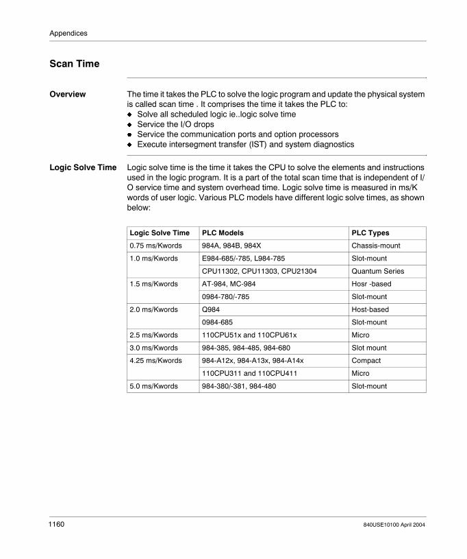
Appendices
Scan Time
Overview The time it takes the PLC to solve the logic program and update the physical system is called scan time . It comprises the time it takes the PLC to: � Solve all scheduled logic ie..logic solve time� Service the I/O drops� Service the communication ports and option processors� Execute intersegment transfer (IST) and system diagnostics
Logic Solve Time Logic solve time is the time it takes the CPU to solve the elements and instructions used in the logic program. It is a part of the total scan time that is independent of I/O service time and system overhead time. Logic solve time is measured in ms/K words of user logic. Various PLC models have different logic solve times, as shown below:
Logic Solve Time PLC Models PLC Types
0.75 ms/Kwords 984A, 984B, 984X Chassis-mount
1.0 ms/Kwords E984-685/-785, L984-785 Slot-mount
CPU11302, CPU11303, CPU21304 Quantum Series
1.5 ms/Kwords AT-984, MC-984 Hosr -based
0984-780/-785 Slot-mount
2.0 ms/Kwords Q984 Host-based
0984-685 Slot-mount
2.5 ms/Kwords 110CPU51x and 110CPU61x Micro
3.0 ms/Kwords 984-385, 984-485, 984-680 Slot mount
4.25 ms/Kwords 984-A12x, 984-A13x, 984-A14x Compact
110CPU311 and 110CPU411 Micro
5.0 ms/Kwords 984-380/-381, 984-480 Slot-mount
1160 840USE10100 April 2004
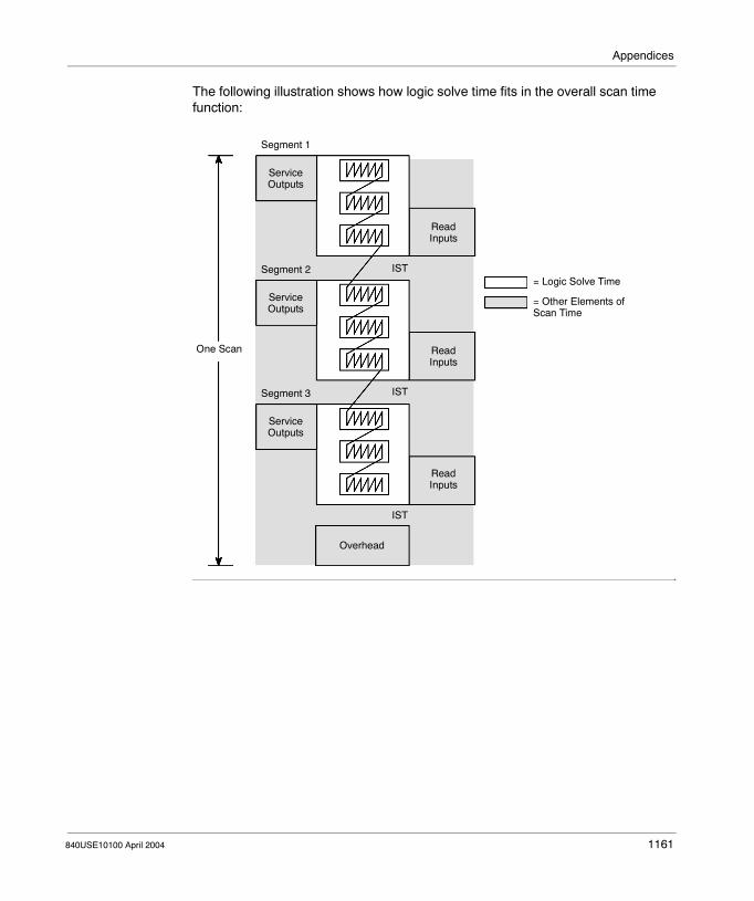
Appendices
The following illustration shows how logic solve time fits in the overall scan time function:
Segment 1
ServiceOutputs
Segment 2
ServiceOutputs
Segment 3
ServiceOutputs
ReadInputs
ReadInputs
ReadInputs
IST
IST
IST
Overhead
= Logic Solve Time
= Other Elements ofScan Time
One Scan
840USE10100 April 2004 1161

Appendices
Servicing the I/O In order to handle system throughput efficiently, the PLC coordinates the solution of logic segments via its CPU and the servicing of I/O drops via its I/O processor. Typically a logic segment is coordinated with a particular I/O drop—for example, the logic networks in segment 2 correspond to the real-world I/O points at drop 2. Inputs are read during the previous segment and outputs are written during the subsequent segment.This method of I/O servicing assures that the most recent input status is available for logic solve and that outputs are written as soon as possible after logic solve. It ensures predictability between the PLC and the process it is controlling.
Segment 1
ServiceOutputs
Segment 2
ServiceOutputs
Segment 3
ServiceDrop 2
ReadInputs
ReadInputs
IST
IST
IST
Overhead
= Other Elements ofScan Time
One Scan
Outputs
ReadDrop 2Inputs
= I/O Service Timefor Drop 2
1162 840USE10100 April 2004

Appendices
Overhead An intersegment transfer (IST) occurs between each segment. At this time, the I/O processor and the state RAM exchange data; previous inputs are transferred to state RAM and the next outputs are transferred to the I/O processor. The logic scan and I/O servicing for each segment are coordinated in this fashion. Using direct memory access (DMA), ISTs typically take less than 1 ms/segment.At the end of each scan, input messages to the Modbus communication ports are serviced. The maximum time allotted for comm port servicing is 2.5 ms/scan; typical servicing times are less than 1 ms/scan. If the PLC is using any option processors (C986 Coprocessors or D908 Distributed Communications Processors), they are also serviced at the end of each scan and typically require less than 1 ms/scan.System diagnostics take from 1 ... 2 ms/scan to run, depending on PLC type.
Segment 1
ServiceOutputs
Segment 2
ServiceOutputs
Segment 3
ServiceOutputs
ReadInputs
ReadInputs
ReadInputs
IST
IST
IST
Overhead
= Overhead
= Other Elements ofScan Time
One Scan
Support Time
840USE10100 April 2004 1163

Appendices
How to Measure Scan Time
Overview The following ladder logic circuit can be used in your application program to evaluate system scan time:
The up-counter counts 1000 scans as it transitions 500 times. When the counter has transitioned 500 times, the T.01 timer turns OFF and stores the number of hundredths of seconds it has taken for the counter to transition 500 times (1000 scans) in register 40003.The value stored in 40002/40003 in the DIV block is then divided by 100 and the result—which represents logic solve time in ms is stored in register 40005.
Note: 10001 is controlled via a DISABLE or a hard-wired input; ifyou are running the program in optimized mode, a hard-wired input isrequired to toggle 10001.
Note: The maximum amount of time allowed for a scan is 250 ms; if the scan has not completed in that amount of time, a watchdog timer in the CPU stops the application and sends a timeout error message to the programming panel display. The maximum limit on scan time protects the PLC from entering into an infinite loop.
UCTR
T.01
DIV
1164 840USE10100 April 2004

Appendices
Maximizing Throughput
Overview The PLC architecture simultaneously solves logic and services I/O drops to optimize system throughput. Throughput is the time it takes for a signal received at a field sensing device to be sent as an input to the PLC, processed in ladder logic, and returned as an output signal to a field working device. Throughput time may be longer or shorter than a single scan; it gives you a realistic measure of the system’s actual performance.
The Ideal Throughput Situation
If the default segment scheduler is in place, the system automatically solves the logic starting at segment 1 and moving sequentially through segment n. Throughput is optimized when logic referring to real-world I/O is contained in the segment that corresponds to that I/O drop.For instance, if you are using I/O in drop 1 of a three-drop system to control a pushbutton that starts a motor, the ideal condition is for logic segment 1 to contain all the appropriate logic:
When all logic segments are coordinated with all physical I/O drops in this manner, the throughput for a given logic segment can be less than one scan. Here is how it can be traced in our scan time model:
PLC
I/ODrop1
I/ODrop2
I/ODrop3
10001
00001
0000110001
Segment 1
840USE10100 April 2004 1165

Appendices
The model tracks throughput for drop 3. Throughput in this best case example is about 75% of total scan time. Five benchmark events are shown:� Event A, where the inputs from drop 3 are available to the I/O processor.� Event B, where the I/O processor transfers data to state RAM.� Event C, where the segment 3 logic networks are solved.� Event D, where data is transferred from state RAM to the I/O processor � Event E, where the output data is written to the input modules at drop 3
Segment 1
ServiceDrop 3
Segment 2
ServiceOutputs
Segment 3
ServiceOutputs
ReadInputs
ReadDrop 3
ReadInputs
IST
IST
IST
Overhead
Scan 1
Outputs
Inputs
ServiceDrop 3Outputs
Segment 1
ReadInputs
Scan 2
Event A
Event B
Event C
Event D
Event E
1166 840USE10100 April 2004
Appendices
Order of Solve
Overview You specify the number of segments and I/O drops with the configurator editor in your panel software package. The default order-of-solve condition is segment 1 through segment n consecutively and continuously, once per scan, with the corresponding I/O drops serviced in like order. You are able to change the order of solve using the segment scheduler editor in your panel software package. There may be times when you can modify the order of solve to improve overall system performance. The segment scheduler can be used effectively to:� Improve throughput for critical I/O� Improve overall system performance� Optimize the servicing of communication ports
840USE10100 April 2004 1167
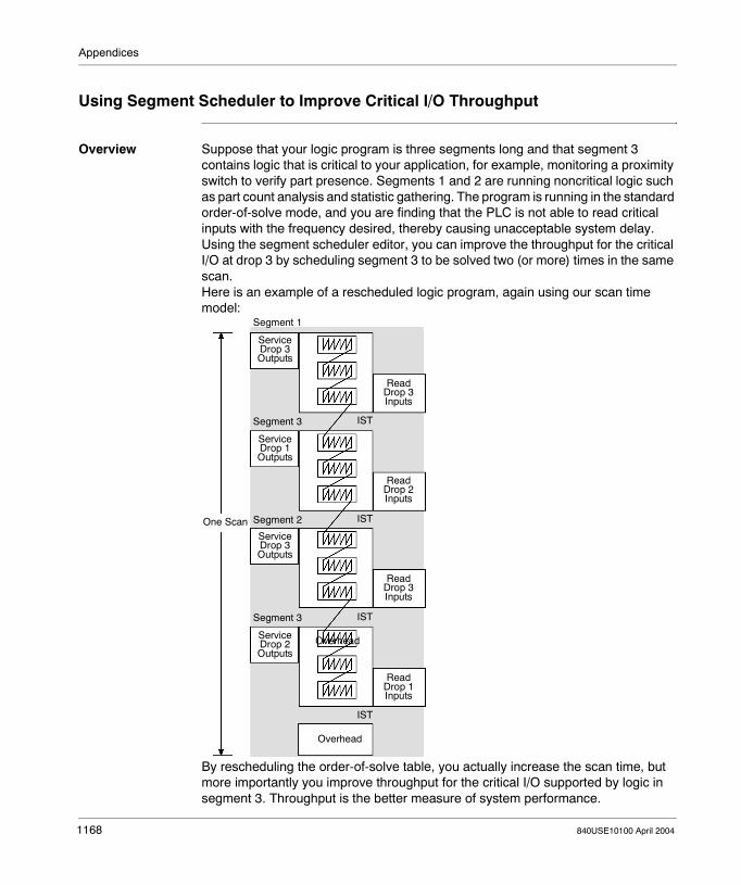
Appendices
Using Segment Scheduler to Improve Critical I/O Throughput
Overview Suppose that your logic program is three segments long and that segment 3 contains logic that is critical to your application, for example, monitoring a proximity switch to verify part presence. Segments 1 and 2 are running noncritical logic such as part count analysis and statistic gathering. The program is running in the standard order-of-solve mode, and you are finding that the PLC is not able to read critical inputs with the frequency desired, thereby causing unacceptable system delay. Using the segment scheduler editor, you can improve the throughput for the critical I/O at drop 3 by scheduling segment 3 to be solved two (or more) times in the same scan.Here is an example of a rescheduled logic program, again using our scan time model:
By rescheduling the order-of-solve table, you actually increase the scan time, but more importantly you improve throughput for the critical I/O supported by logic in segment 3. Throughput is the better measure of system performance.
Segment 1
ServiceDrop 3
Segment 3
Segment 2
IST
IST
IST
Overhead
One Scan
Overhead
IST
Segment 3
Outputs
ServiceDrop 1Outputs
ServiceDrop 3Outputs
ServiceDrop 2Outputs
ReadDrop 3Inputs
ReadDrop 2Inputs
ReadDrop 3Inputs
ReadDrop 1Inputs
1168 840USE10100 April 2004

Appendices
Using Segment Scheduler to Improve System Performance
Overview When certain areas of a ladder logic program do not need to be solved continually on every scan. For example, an alarm handling routine, a data analysis routine, or some diagnostic message routines can be designated as controlled segments by the segment scheduler editor. Based on the status of an I/O or internal reference, a controlled segment may be scheduled to be skipped, thereby reducing scan time and improving overall system throughput. For example, suppose that you have some alarm handling logic in segment 2 of a three-segment logic program. You can use the segment scheduler editor to control segment 2 based on the status of a coil 00056—if the coil is ON, segment 2 logic will be activated in the scan, and if the coil is OFF the segment will not be solved in the scan.
840USE10100 April 2004 1169

Appendices
Using Segment Scheduler to Improve Communication Port Servicing
Overview When you find that the frequency of standard end-of-scan servicing of communication ports, option processors, or system diagnostics is inadequate for your application requirements, you can increase service frequency by inserting one or more reset watchdog timer routines in the order-of-solve table. Each time this routine is encountered by the CPU, it causes all communication ports to be serviced and causes the system diagnostics to be run.
1170 840USE10100 April 2004

Appendices
Sweep Functions
Overview Sweep functions allow you to scan a logic program at fixed intervals. They do not make the PLC solve logic faster or terminate scans prematurely.
Constant Sweep Constant Sweep allows you to set target scan times from 10 ... 200 ms (in multiples of 10). A target scan time is the time between the start of one scan and the start of the next; it is not the time between the end of one scan and the beginning of the next.Constant Sweep is useful in applications where data must be sampled at constant time intervals. If a Constant Sweep is invoked with a time lapse smaller than the actual scan time, the time lapse is ignored and the system uses its own normal scan rate. The Constant Sweep target scan time encompasses logic solving, I/O and Modbus port servicing, and system diagnostics. If you set a target scan of 40 ms and the logic solving, I/O servicing, and diagnostics require only 30 ms, the PLC will wait 10 ms on each scan.
Single Sweep The Single Sweep function allows your PLC to execute a fixed number of scans (from 1 ... 15) and then to stop solving logic but continue servicing I/O. This function is useful for diagnostic work; it allows solved logic, moved data, and performed calculations to be examined for errors.
WARNING
The Single Sweep function should not be used to debug controls on machine tools, processes, or material handling systems when they are active. Once a specified number of scans has been solved, all outputs are frozen in their last state. Since no logic solving is taking place, the PLCignores all input information. This can result in unsafe, hazardous, and destructive operation of the machine or process connected to the PLC.
Failure to follow this precaution can result in death, serious injury, or equipment damage.
840USE10100 April 2004 1171

Appendices
1172 840USE10100 April 2004
Glossary
active window The window, which is currently selected. Only one window can be active at any one given time. When a window is active, the heading changes color, in order to distinguish it from other windows. Unselected windows are inactive.
Actual parameter Currently connected Input/Output parameters.
Addresses (Direct) addresses are memory areas on the PLC. These are found in the State RAM and can be assigned input/output modules.The display/input of direct addresses is possible in the following formats:� Standard format (400001)� Separator format (4:00001)� Compact format (4:1)� IEC format (QW1)
ANL_IN ANL_IN stands for the data type "Analog Input" and is used for processing analog values. The 3x References of the configured analog input module, which is specified in the I/O component list is automatically assigned the data type and should therefore only be occupied by Unlocated variables.
ANL_OUT ANL_OUT stands for the data type "Analog Output" and is used for processing analog values. The 4x-References of the configured analog output module, which is specified in the I/O component list is automatically assigned the data type and should therefore only be occupied by Unlocated variables.
ANY In the existing version "ANY" covers the elementary data types BOOL, BYTE, DINT, INT, REAL, UDINT, UINT, TIME and WORD and therefore derived data types.
A
840USE10100 April 2004 xxxv
Glossary
ANY_BIT In the existing version, "ANY_BIT" covers the data types BOOL, BYTE and WORD.
ANY_ELEM In the existing version "ANY_ELEM" covers the elementary data types BOOL, BYTE, DINT, INT, REAL, UDINT, UINT, TIME and WORD.
ANY_INT In the existing version, "ANY_INT" covers the data types DINT, INT, UDINT and UINT.
ANY_NUM In the existing version, "ANY_NUM" covers the data types DINT, INT, REAL, UDINT and UINT.
ANY_REAL In the existing version "ANY_REAL" covers the data type REAL.
Application window
The window, which contains the working area, the menu bar and the tool bar for the application. The name of the application appears in the heading. An application window can contain several document windows. In Concept the application window corresponds to a Project.
Argument Synonymous with Actual parameters.
ASCII mode American Standard Code for Information Interchange. The ASCII mode is used for communication with various host devices. ASCII works with 7 data bits.
Atrium The PC based controller is located on a standard AT board, and can be operated within a host computer in an ISA bus slot. The module occupies a motherboard (requires SA85 driver) with two slots for PC104 daughter boards. From this, a PC104 daughter board is used as a CPU and the others for INTERBUS control.
Back up data file (Concept EFB)
The back up file is a copy of the last Source files. The name of this back up file is "backup??.c" (it is accepted that there are no more than 100 copies of the source files. The first back up file is called "backup00.c". If changes have been made on the Definition file, which do not create any changes to the interface in the EFB, there is no need to create a back up file by editing the source files (Objects → Source). If a back up file can be assigned, the name of the source file can be given.
Base 16 literals Base 16 literals function as the input of whole number values in the hexadecimal system. The base must be denoted by the prefix 16#. The values may not be preceded by signs (+/-). Single underline signs ( _ ) between figures are not significant.
B
xxxvi 840USE10100 April 2004
Glossary
Example 16#F_F or 16#FF (decimal 255)16#E_0 or 16#E0 (decimal 224)
Base 8 literal Base 8 literals function as the input of whole number values in the octal system. The base must be denoted by the prefix 3.63kg. The values may not be preceded by signs (+/-). Single underline signs ( _ ) between figures are not significant.
Example 8#3_1111 or 8#377 (decimal 255) 8#34_1111 or 8#340 (decimal 224)
Basis 2 literals Base 2 literals function as the input of whole number values in the dual system. The base must be denoted by the prefix 0.91kg. The values may not be preceded by signs (+/-). Single underline signs ( _ ) between figures are not significant.
Example 2#1111_1111 or 2#11111111 (decimal 255) 2#1110_1111 or 2#11100000 (decimal 224)
Binary connections
Connections between outputs and inputs of FFBs of data type BOOL.
Bit sequence A data element, which is made up from one or more bits.
BOOL BOOL stands for the data type "Boolean". The length of the data elements is 1 bit (in the memory contained in 1 byte). The range of values for variables of this type is 0 (FALSE) and 1 (TRUE).
Bridge A bridge serves to connect networks. It enables communication between nodes on the two networks. Each network has its own token rotation sequence – the token is not deployed via bridges.
BYTE BYTE stands for the data type "Bit sequence 8". The input appears as Base 2 literal, Base 8 literal or Base 1 16 literal. The length of the data element is 8 bit. A numerical range of values cannot be assigned to this data type.
Cache The cache is a temporary memory for cut or copied objects. These objects can be inserted into sections. The old content in the cache is overwritten for each new Cut or Copy.
C
840USE10100 April 2004 xxxvii

Glossary
Call up The operation, by which the execution of an operation is initiated.
Coil A coil is a LD element, which transfers (without alteration) the status of the horizontal link on the left side to the horizontal link on the right side. In this way, the status is saved in the associated Variable/ direct address.
Compact format (4:1)
The first figure (the Reference) is separated from the following address with a colon (:), where the leading zero are not entered in the address.
Connection A check or flow of data connection between graphic objects (e.g. steps in the SFC editor, Function blocks in the FBD editor) within a section, is graphically shown as a line.
Constants Constants are Unlocated variables, which are assigned a value that cannot be altered from the program logic (write protected).
Contact A contact is a LD element, which transfers a horizontal connection status onto the right side. This status is from the Boolean AND- operation of the horizontal connection status on the left side with the status of the associated Variables/direct Address. A contact does not alter the value of the associated variables/direct address.
Data transfer settings
Settings, which determine how information from the programming device is transferred to the PLC.
Data types The overview shows the hierarchy of data types, as they are used with inputs and outputs of Functions and Function blocks. Generic data types are denoted by the prefix "ANY".� ANY_ELEM
� ANY_NUMANY_REAL (REAL)ANY_INT (DINT, INT, UDINT, UINT)
� ANY_BIT (BOOL, BYTE, WORD)� TIME
� System data types (IEC extensions)� Derived (from "ANY" data types)
D
xxxviii 840USE10100 April 2004

Glossary
DCP I/O station With a Distributed Control Processor (D908) a remote network can be set up with a parent PLC. When using a D908 with remote PLC, the parent PLC views the remote PLC as a remote I/O station. The D908 and the remote PLC communicate via the system bus, which results in high performance, with minimum effect on the cycle time. The data exchange between the D908 and the parent PLC takes place at 1.5 Megabits per second via the remote I/O bus. A parent PLC can support up to 31 (Address 2-32) D908 processors.
DDE (Dynamic Data Exchange)
The DDE interface enables a dynamic data exchange between two programs under Windows. The DDE interface can be used in the extended monitor to call up its own display applications. With this interface, the user (i.e. the DDE client) can not only read data from the extended monitor (DDE server), but also write data onto the PLC via the server. Data can therefore be altered directly in the PLC, while it monitors and analyzes the results. When using this interface, the user is able to make their own "Graphic-Tool", "Face Plate" or "Tuning Tool", and integrate this into the system. The tools can be written in any DDE supporting language, e.g. Visual Basic and Visual-C++. The tools are called up, when the one of the buttons in the dialog box extended monitor uses Concept Graphic Tool: Signals of a projection can be displayed as timing diagrams via the DDE connection between Concept and Concept Graphic Tool.
Decentral Network (DIO)
A remote programming in Modbus Plus network enables maximum data transfer performance and no specific requests on the links. The programming of a remote net is easy. To set up the net, no additional ladder diagram logic is needed. Via corresponding entries into the Peer Cop processor all data transfer requests are met.
Declaration Mechanism for determining the definition of a Language element. A declaration normally covers the connection of an Identifier with a language element and the assignment of attributes such as Data types and algorithms.
Definition data file (Concept EFB)
The definition file contains general descriptive information about the selected FFB and its formal parameters.
Derived data type Derived data types are types of data, which are derived from the Elementary data types and/or other derived data types. The definition of the derived data types appears in the data type editor in Concept.Distinctions are made between global data types and local data types.
Derived Function Block (DFB)
A derived function block represents the Call up of a derived function block type. Details of the graphic form of call up can be found in the definition " Function block (Item)". Contrary to calling up EFB types, calling up DFB types is denoted by double vertical lines on the left and right side of the rectangular block symbol.
840USE10100 April 2004 xxxix

Glossary
The body of a derived function block type is designed using FBD language, but only in the current version of the programming system. Other IEC languages cannot yet be used for defining DFB types, nor can derived functions be defined in the current version.Distinctions are made between local and global DFBs.
DINT DINT stands for the data type "double integer". The input appears as Integer literal, Base 2 literal, Base 8 literal or Base 16 literal. The length of the data element is 32 bit. The range of values for variables of this data type is from –2 exp (31) to 2 exp (31) –1.
Direct display A method of displaying variables in the PLC program, from which the assignment of configured memory can be directly and indirectly derived from the physical memory.
Document window
A window within an Application window. Several document windows can be opened at the same time in an application window. However, only one document window can be active. Document windows in Concept are, for example, sections, the message window, the reference data editor and the PLC configuration.
Dummy An empty data file, which consists of a text header with general file information, i.e. author, date of creation, EFB identifier etc. The user must complete this dummy file with additional entries.
DX Zoom This property enables connection to a programming object to observe and, if necessary, change its data value.
Elementary functions/function blocks (EFB)
Identifier for Functions or Function blocks, whose type definitions are not formulated in one of the IEC languages, i.e. whose bodies, for example, cannot be modified with the DFB Editor (Concept-DFB). EFB types are programmed in "C" and mounted via Libraries in precompiled form.
E
xl 840USE10100 April 2004

Glossary
EN / ENO (Enable / Error display)
If the value of EN is "0" when the FFB is called up, the algorithms defined by the FFB are not executed and all outputs contain the previous value. The value of ENO is automatically set to "0" in this case. If the value of EN is "1" when the FFB is called up, the algorithms defined by the FFB are executed. After the error free execution of the algorithms, the ENO value is automatically set to "1". If an error occurs during the execution of the algorithm, ENO is automatically set to "0". The output behavior of the FFB depends whether the FFBs are called up without EN/ENO or with EN=1. If the EN/ENO display is enabled, the EN input must be active. Otherwise, the FFB is not executed. The projection of EN and ENO is enabled/disabled in the block properties dialog box. The dialog box is called up via the menu commands Objects → Properties... or via a double click on the FFB.
Error When processing a FFB or a Step an error is detected (e.g. unauthorized input value or a time error), an error message appears, which can be viewed with the menu command Online → Event display... . With FFBs the ENO output is set to "0".
Evaluation The process, by which a value for a Function or for the outputs of a Function block during the Program execution is transmitted.
Expression Expressions consist of operators and operands.
FFB (functions/function blocks)
Collective term for EFB (elementary functions/function blocks) and DFB (derived function blocks)
Field variables Variables, one of which is assigned, with the assistance of the key word ARRAY (field), a defined Derived data type. A field is a collection of data elements of the same Data type.
FIR filter Finite Impulse Response Filter
Formal parameters
Input/Output parameters, which are used within the logic of a FFB and led out of the FFB as inputs/outputs.
F
840USE10100 April 2004 xli
Glossary
Function (FUNC) A Program organization unit, which exactly supplies a data element when executing. A function has no internal status information. Multiple call ups of the same function with the same input parameter values always supply the same output values.Details of the graphic form of function call up can be found in the definition " Function block (Item)". In contrast to the call up of function blocks, the function call ups only have one unnamed output, whose name is the name of the function itself. In FBD each call up is denoted by a unique number over the graphic block; this number is automatically generated and cannot be altered.
Function block (item) (FB)
A function block is a Program organization unit, which correspondingly calculates the functionality values, defined in the function block type description, for the output and internal variables, when it is called up as a certain item. All output values and internal variables of a certain function block item remain as a call up of the function block until the next. Multiple call up of the same function block item with the same arguments (Input parameter values) supply generally supply the same output value(s).Each function block item is displayed graphically by a rectangular block symbol. The name of the function block type is located on the top center within the rectangle. The name of the function block item is located also at the top, but on the outside of the rectangle. An instance is automatically generated when creating, which can however be altered manually, if required. Inputs are displayed on the left side and outputs on the right of the block. The names of the formal input/output parameters are displayed within the rectangle in the corresponding places.The above description of the graphic presentation is principally applicable to Function call ups and to DFB call ups. Differences are described in the corresponding definitions.
Function block dialog (FBD)
One or more sections, which contain graphically displayed networks from Functions, Function blocks and Connections.
Function block type
A language element, consisting of: 1. the definition of a data structure, subdivided into input, output and internal variables, 2. A set of operations, which is used with the elements of the data structure, when a function block type instance is called up. This set of operations can be formulated either in one of the IEC languages (DFB type) or in "C" (EFB type). A function block type can be instanced (called up) several times.
Function counter The function counter serves as a unique identifier for the function in a Program or DFB. The function counter cannot be edited and is automatically assigned. The function counter always has the structure: .n.m
n = Section number (number running)m = Number of the FFB object in the section (number running)
xlii 840USE10100 April 2004

Glossary
Generic data type
A Data type, which stands in for several other data types.
Generic literal If the Data type of a literal is not relevant, simply enter the value for the literal. In this case Concept automatically assigns the literal to a suitable data type.
Global derived data types
Global Derived data types are available in every Concept project and are contained in the DFB directory directly under the Concept directory.
Global DFBs Global DFBs are available in every Concept project and are contained in the DFB directory directly under the Concept directory.
Global macros Global Macros are available in every Concept project and are contained in the DFB directory directly under the Concept directory.
Groups (EFBs) Some EFB libraries (e.g. the IEC library) are subdivided into groups. This facilitates the search for FFBs, especially in extensive libraries.
I/O component list
The I/O and expert assemblies of the various CPUs are configured in the I/O component list.
IEC 61131-3 International norm: Programmable controllers – part 3: Programming languages.
IEC format (QW1) In the place of the address stands an IEC identifier, followed by a five figure address:� %0x12345 = %Q12345� %1x12345 = %I12345� %3x12345 = %IW12345� %4x12345 = %QW12345
G
I
840USE10100 April 2004 xliii
Glossary
IEC name conventions (identifier)
An identifier is a sequence of letters, figures, and underscores, which must start with a letter or underscores (e.g. name of a function block type, of an item or section). Letters from national sets of characters (e.g. ö,ü, é, õ) can be used, taken from project and DFB names.Underscores are significant in identifiers; e.g. "A_BCD" and "AB_CD" are interpreted as different identifiers. Several leading and multiple underscores are not authorized consecutively.Identifiers are not permitted to contain space characters. Upper and/or lower case is not significant; e.g. "ABCD" and "abcd" are interpreted as the same identifier.Identifiers are not permitted to be Key words.
IIR filter Infinite Impulse Response Filter
Initial step (starting step)
The first step in a chain. In each chain, an initial step must be defined. The chain is started with the initial step when first called up.
Initial value The allocated value of one of the variables when starting the program. The value assignment appears in the form of a Literal.
Input bits (1x references)
The 1/0 status of input bits is controlled via the process data, which reaches the CPU from an entry device.
Input parameters (Input)
When calling up a FFB the associated Argument is transferred.
Input words (3x references)
An input word contains information, which come from an external source and are represented by a 16 bit figure. A 3x register can also contain 16 sequential input bits, which were read into the register in binary or BCD (binary coded decimal) format. Note: The x, which comes after the first figure of the reference type, represents a five figure storage location in the user data store, i.e. if the reference 300201 signifies a 16 bit input word in the address 201 of the State RAM.
Instantiation The generation of an Item.
Instruction (IL) Instructions are "commands" of the IL programming language. Each operation begins on a new line and is succeeded by an operator (with modifier if needed) and, if necessary for each relevant operation, by one or more operands. If several operands are used, they are separated by commas. A tag can stand before the instruction, which is followed by a colon. The commentary must, if available, be the last element in the line.
Note: The x, which comes after the first figure of the reference type, represents a five figure storage location in the application data store, i.e. if the reference 100201 signifies an input bit in the address 201 of the State RAM.
xliv 840USE10100 April 2004
Glossary
Instruction (LL984)
When programming electric controllers, the task of implementing operational coded instructions in the form of picture objects, which are divided into recognizable contact forms, must be executed. The designed program objects are, on the user level, converted to computer useable OP codes during the loading process. The OP codes are deciphered in the CPU and processed by the controller’s firmware functions so that the desired controller is implemented.
Instruction list (IL)
IL is a text language according to IEC 1131, in which operations, e.g. conditional/unconditional call up of Function blocks and Functions, conditional/unconditional jumps etc. are displayed through instructions.
INT INT stands for the data type "whole number". The input appears as Integer literal, Base 2 literal, Base 8 literal or Base 16 literal. The length of the data element is 16 bit. The range of values for variables of this data type is from –2 exp (15) to 2 exp (15) –1.
Integer literals Integer literals function as the input of whole number values in the decimal system. The values may be preceded by the signs (+/-). Single underline signs ( _ ) between figures are not significant.
Example -12, 0, 123_456, +986
INTERBUS (PCP) To use the INTERBUS PCP channel and the INTERBUS process data preprocessing (PDP), the new I/O station type INTERBUS (PCP) is led into the Concept configurator. This I/O station type is assigned fixed to the INTERBUS connection module 180-CRP-660-01.The 180-CRP-660-01 differs from the 180-CRP-660-00 only by a clearly larger I/O area in the state RAM of the controller.
Item name An Identifier, which belongs to a certain Function block item. The item name serves as a unique identifier for the function block in a program organization unit. The item name is automatically generated, but can be edited. The item name must be unique throughout the Program organization unit, and no distinction is made between upper/lower case. If the given name already exists, a warning is given and another name must be selected. The item name must conform to the IEC name conventions, otherwise an error message appears. The automatically generated instance name always has the structure: FBI_n_m
FBI = Function block itemn = Section number (number running)m = Number of the FFB object in the section (number running)
840USE10100 April 2004 xlv

Glossary
Jump Element of the SFC language. Jumps are used to jump over areas of the chain.
Key words Key words are unique combinations of figures, which are used as special syntactic elements, as is defined in appendix B of the IEC 1131-3. All key words, which are used in the IEC 1131-3 and in Concept, are listed in appendix C of the IEC 1131-3. These listed keywords cannot be used for any other purpose, i.e. not as variable names, section names, item names etc.
Ladder Diagram (LD)
Ladder Diagram is a graphic programming language according to IEC1131, which optically orientates itself to the "rung" of a relay ladder diagram.
Ladder Logic 984 (LL)
In the terms Ladder Logic and Ladder Diagram, the word Ladder refers to execution. In contrast to a diagram, a ladder logic is used by engineers to draw up a circuit (with assistance from electrical symbols),which should chart the cycle of events and not the existing wires, which connect the parts together. A usual user interface for controlling the action by automated devices permits ladder logic interfaces, so that when implementing a control system, engineers do not have to learn any new programming languages, with which they are not conversant.The structure of the actual ladder logic enables electrical elements to be linked in a way that generates a control output, which is dependant upon a configured flow of power through the electrical objects used, which displays the previously demanded condition of a physical electric appliance.In simple form, the user interface is one of the video displays used by the PLC programming application, which establishes a vertical and horizontal grid, in which the programming objects are arranged. The logic is powered from the left side of the grid, and by connecting activated objects the electricity flows from left to right.
Landscape format
Landscape format means that the page is wider than it is long when looking at the printed text.
J
K
L
xlvi 840USE10100 April 2004
Glossary
Language element
Each basic element in one of the IEC programming languages, e.g. a Step in SFC, a Function block item in FBD or the Start value of a variable.
Library Collection of software objects, which are provided for reuse when programming new projects, or even when building new libraries. Examples are the Elementary function block types libraries.EFB libraries can be subdivided into Groups.
Literals Literals serve to directly supply values to inputs of FFBs, transition conditions etc. These values cannot be overwritten by the program logic (write protected). In this way, generic and standardized literals are differentiated.Furthermore literals serve to assign a Constant a value or a Variable an Initial value. The input appears as Base 2 literal, Base 8 literal, Base 16 literal, Integer literal, Real literal or Real literal with exponent.
Local derived data types
Local derived data types are only available in a single Concept project and its local DFBs and are contained in the DFB directory under the project directory.
Local DFBs Local DFBs are only available in a single Concept project and are contained in the DFB directory under the project directory.
Local link The local network link is the network, which links the local nodes with other nodes either directly or via a bus amplifier.
Local macros Local Macros are only available in a single Concept project and are contained in the DFB directory under the project directory.
Local network nodes
The local node is the one, which is projected evenly.
Located variable Located variables are assigned a state RAM address (reference addresses 0x,1x, 3x, 4x). The value of these variables is saved in the state RAM and can be altered online with the reference data editor. These variables can be addressed by symbolic names or the reference addresses.
Collective PLC inputs and outputs are connected to the state RAM. The program access to the peripheral signals, which are connected to the PLC, appears only via located variables. PLC access from external sides via Modbus or Modbus plus interfaces, i.e. from visualizing systems, are likewise possible via located variables.
840USE10100 April 2004 xlvii

Glossary
Macro Macros are created with help from the software Concept DFB.Macros function to duplicate frequently used sections and networks (including the logic, variables, and variable declaration).Distinctions are made between local and global macros.
Macros have the following properties:� Macros can only be created in the programming languages FBD and LD.� Macros only contain one single section.� Macros can contain any complex section.� From a program technical point of view, there is no differentiation between an
instanced macro, i.e. a macro inserted into a section, and a conventionally created macro.
� Calling up DFBs in a macro� Variable declaration� Use of macro-own data structures� Automatic acceptance of the variables declared in the macro� Initial value for variables� Multiple instancing of a macro in the whole program with different variables� The section name, the variable name and the data structure name can contain up
to 10 different exchange markings (@0 to @9).
MMI Man Machine Interface
Multi element variables
Variables, one of which is assigned a Derived data type defined with STRUCT or ARRAY.Distinctions are made between Field variables and structured variables.
Network A network is the connection of devices to a common data path, which communicate with each other via a common protocol.
Network node A node is a device with an address (164) on the Modbus Plus network.
M
N
xlviii 840USE10100 April 2004

Glossary
Node address The node address serves a unique identifier for the network in the routing path. The address is set directly on the node, e.g. with a rotary switch on the back of the module.
Operand An operand is a Literal, a Variable, a Function call up or an Expression.
Operator An operator is a symbol for an arithmetic or Boolean operation to be executed.
Output parameters (Output)
A parameter, with which the result(s) of the Evaluation of a FFB are returned.
Output/discretes (0x references)
An output/marker bit can be used to control real output data via an output unit of the control system, or to define one or more outputs in the state RAM. Note: The x, which comes after the first figure of the reference type, represents a five figure storage location in the application data store, i.e. if the reference 000201 signifies an output or marker bit in the address 201 of the State RAM.
Output/marker words (4x references)
An output/marker word can be used to save numerical data (binary or decimal) in the State RAM, or also to send data from the CPU to an output unit in the control system. Note: The x, which comes after the first figure of the reference type, represents a five figure storage location in the application data store, i.e. if the reference 400201 signifies a 16 bit output or marker word in the address 201 of the State RAM.
Peer processor The peer processor processes the token run and the flow of data between the Modbus Plus network and the PLC application logic.
PLC Programmable controller
Program The uppermost Program organization unit. A program is closed and loaded onto a single PLC.
Program cycle A program cycle consists of reading in the inputs, processing the program logic and the output of the outputs.
O
P
840USE10100 April 2004 xlix

Glossary
Program organization unit
A Function, a Function block, or a Program. This term can refer to either a Type or an Item.
Programming device
Hardware and software, which supports programming, configuring, testing, implementing and error searching in PLC applications as well as in remote system applications, to enable source documentation and archiving. The programming device could also be used for process visualization.
Programming redundancy system (Hot Standby)
A redundancy system consists of two identically configured PLC devices, which communicate with each other via redundancy processors. In the case of the primary PLC failing, the secondary PLC takes over the control checks. Under normal conditions the secondary PLC does not take over any controlling functions, but instead checks the status information, to detect mistakes.
Project General identification of the uppermost level of a software tree structure, which specifies the parent project name of a PLC application. After specifying the project name, the system configuration and control program can be saved under this name. All data, which results during the creation of the configuration and the program, belongs to this parent project for this special automation.General identification for the complete set of programming and configuring information in the Project data bank, which displays the source code that describes the automation of a system.
Project data bank The data bank in the Programming device, which contains the projection information for a Project.
Prototype data file (Concept EFB)
The prototype data file contains all prototypes of the assigned functions. Further, if available, a type definition of the internal status structure is given.
REAL REAL stands for the data type "real". The input appears as Real literal or as Real literal with exponent. The length of the data element is 32 bit. The value range for variables of this data type reaches from 8.43E-37 to 3.36E+38.
R
Note: Depending on the mathematic processor type of the CPU, various areas within this valid value range cannot be represented. This is valid for values nearing ZERO and for values nearing INFINITY. In these cases, a number value is not shown in animation, instead NAN (Not A Number) oder INF (INFinite).
l 840USE10100 April 2004

Glossary
Real literal Real literals function as the input of real values in the decimal system. Real literals are denoted by the input of the decimal point. The values may be preceded by the signs (+/-). Single underline signs ( _ ) between figures are not significant.
Example -12.0, 0.0, +0.456, 3.14159_26
Real literal with exponent
Real literals with exponent function as the input of real values in the decimal system. Real literals with exponent are denoted by the input of the decimal point. The exponent sets the key potency, by which the preceding number is multiplied to get to the value to be displayed. The basis may be preceded by a negative sign (-). The exponent may be preceded by a positive or negative sign (+/-). Single underline signs ( _ ) between figures are not significant. (Only between numbers, not before or after the decimal poiont and not before or after "E", "E+" or "E-")
Example -1.34E-12 or -1.34e-12 1.0E+6 or 1.0e+61.234E6 or 1.234e6
Reference Each direct address is a reference, which starts with an ID, specifying whether it concerns an input or an output and whether it concerns a bit or a word. References, which start with the code 6, display the register in the extended memory of the state RAM. 0x area = Discrete outputs 1x area = Input bits 3x area = Input words 4x area = Output bits/Marker words 6x area = Register in the extended memory
Register in the extended memory (6x reference)
6x references are marker words in the extended memory of the PLC. Only LL984 user programs and CPU 213 04 or CPU 424 02 can be used.
RIO (Remote I/O) Remote I/O provides a physical location of the I/O coordinate setting device in relation to the processor to be controlled. Remote inputs/outputs are connected to the consumer control via a wired communication cable.
RP (PROFIBUS) RP = Remote Peripheral
Note: The x, which comes after the first figure of each reference type, represents a five figure storage location in the application data store, i.e. if the reference 400201 signifies a 16 bit output or marker word in the address 201 of the State RAM.
840USE10100 April 2004 li

Glossary
RTU mode Remote Terminal UnitThe RTU mode is used for communication between the PLC and an IBM compatible personal computer. RTU works with 8 data bits.
Rum-time error Error, which occurs during program processing on the PLC, with SFC objects (i.e. steps) or FFBs. These are, for example, over-runs of value ranges with figures, or time errors with steps.
SA85 module The SA85 module is a Modbus Plus adapter for an IBM-AT or compatible computer.
Section A section can be used, for example, to describe the functioning method of a technological unit, such as a motor.A Program or DFB consist of one or more sections. Sections can be programmed with the IEC programming languages FBD and SFC. Only one of the named programming languages can be used within a section.Each section has its own Document window in Concept. For reasons of clarity, it is recommended to subdivide a very large section into several small ones. The scroll bar serves to assist scrolling in a section.
Separator format (4:00001)
The first figure (the Reference) is separated from the ensuing five figure address by a colon (:).
Sequence language (SFC)
The SFC Language elements enable the subdivision of a PLC program organiza-tional unit in a number of Steps and Transitions, which are connected horizontally by aligned Connections. A number of actions belong to each step, and a transition condition is linked to a transition.
Serial ports With serial ports (COM) the information is transferred bit by bit.
Source code data file (Concept EFB)
The source code data file is a usual C++ source file. After execution of the menu command Library → Generate data files this file contains an EFB code framework, in which a specific code must be entered for the selected EFB. To do this, click on the menu command Objects → Source.
Standard format (400001)
The five figure address is located directly after the first figure (the reference).
S
lii 840USE10100 April 2004

Glossary
Standardized literals
If the data type for the literal is to be automatically determined, use the following construction: ’Data type name’#’Literal value’.
Example INT#15 (Data type: Integer, value: 15), BYTE#00001111 (data type: Byte, value: 00001111) REAL#23.0 (Data type: Real, value: 23.0)
For the assignment of REAL data types, there is also the possibility to enter the value in the following way: 23.0. Entering a comma will automatically assign the data type REAL.
State RAM The state RAM is the storage for all sizes, which are addressed in the user program via References (Direct display). For example, input bits, discretes, input words, and discrete words are located in the state RAM.
Statement (ST) Instructions are "commands" of the ST programming language. Instructions must be terminated with semicolons. Several instructions (separated by semi-colons) can occupy the same line.
Status bits There is a status bit for every node with a global input or specific input/output of Peer Cop data. If a defined group of data was successfully transferred within the set time out, the corresponding status bit is set to 1. Alternatively, this bit is set to 0 and all data belonging to this group (of 0) is deleted.
Step SFC Language element: Situations, in which the Program behavior follows in relation to the inputs and outputs of the same operations, which are defined by the associated actions of the step.
Step name The step name functions as the unique flag of a step in a Program organization unit. The step name is automatically generated, but can be edited. The step name must be unique throughout the whole program organization unit, otherwise an Error message appears. The automatically generated step name always has the structure: S_n_m
S = Step n = Section number (number running)m = Number of steps in the section (number running)
Structured text (ST)
ST is a text language according to IEC 1131, in which operations, e.g. call up of Function blocks and Functions, conditional execution of instructions, repetition of instructions etc. are displayed through instructions.
840USE10100 April 2004 liii

Glossary
Structured variables
Variables, one of which is assigned a Derived data type defined with STRUCT (structure).A structure is a collection of data elements with generally differing data types ( Elementary data types and/or derived data types).
SY/MAX In Quantum control devices, Concept closes the mounting on the I/O population SY/MAX I/O modules for RIO control via the Quantum PLC with on. The SY/MAX remote subrack has a remote I/O adapter in slot 1, which communicates via a Modicon S908 R I/O system. The SY/MAX I/O modules are performed when highlighting and including in the I/O population of the Concept configuration.
Symbol (Icon) Graphic display of various objects in Windows, e.g. drives, user programs and Document windows.
Template data file (Concept EFB)
The template data file is an ASCII data file with a layout information for the Concept FBD editor, and the parameters for code generation.
TIME TIME stands for the data type "Time span". The input appears as Time span literal. The length of the data element is 32 bit. The value range for variables of this type stretches from 0 to 2exp(32)-1. The unit for the data type TIME is 1 ms.
Time span literals
Permitted units for time spans (TIME) are days (D), hours (H), minutes (M), seconds (S) and milliseconds (MS) or a combination thereof. The time span must be denoted by the prefix t#, T#, time# or TIME#. An "overrun" of the highest ranking unit is permitted, i.e. the input T#25H15M is permitted.
Example t#14MS, T#14.7S, time#18M, TIME#19.9H, t#20.4D, T#25H15M, time#5D14H12M18S3.5MS
Token The network "Token" controls the temporary property of the transfer rights via a single node. The token runs through the node in a circulating (rising) address sequence. All nodes track the Token run through and can contain all possible data sent with it.
Traffic Cop The Traffic Cop is a component list, which is compiled from the user component list. The Traffic Cop is managed in the PLC and in addition contains the user component list e.g. Status information of the I/O stations and modules.
T
liv 840USE10100 April 2004

Glossary
Transition The condition with which the control of one or more Previous steps transfers to one or more ensuing steps along a directional Link.
UDEFB User defined elementary functions/function blocksFunctions or Function blocks, which were created in the programming language C, and are available in Concept Libraries.
UDINT UDINT stands for the data type "unsigned double integer". The input appears as Integer literal, Base 2 literal, Base 8 literal or Base 16 literal. The length of the data element is 32 bit. The value range for variables of this type stretches from 0 to 2exp(32)-1.
UINT UINT stands for the data type "unsigned integer". The input appears as Integer literal, Base 2 literal, Base 8 literal or Base 16 literal. The length of the data element is 16 bit. The value range for variables of this type stretches from 0 to (2exp16)-1.
Unlocated variable
Unlocated variables are not assigned any state RAM addresses. They therefore do not occupy any state RAM addresses. The value of these variables is saved in the system and can be altered with the reference data editor. These variables are only addressed by symbolic names.
Signals requiring no peripheral access, e.g. intermediate results, system tags etc, should primarily be declared as unlocated variables.
Variables Variables function as a data exchange within sections between several sections and between the Program and the PLC.Variables consist of at least a variable name and a Data type.Should a variable be assigned a direct Address (Reference), it is referred to as a Located variable. Should a variable not be assigned a direct address, it is referred to as an unlocated variable. If the variable is assigned a Derived data type, it is referred to as a Multi-element variable.Otherwise there are Constants and Literals.
U
V
840USE10100 April 2004 lv

Glossary
Vertical format Vertical format means that the page is higher than it is wide when looking at the printed text.
Warning When processing a FFB or a Step a critical status is detected (e.g. critical input value or a time out), a warning appears, which can be viewed with the menu command Online → Event display... . With FFBs the ENO output remains at "1".
WORD WORD stands for the data type "Bit sequence 16". The input appears as Base 2 literal, Base 8 literal or Base 1 16 literal. The length of the data element is 16 bit. A numerical range of values cannot be assigned to this data type.
W
lvi 840USE10100 April 2004
CBAIndex
Numerics3x or 4x register
entering in equation network, 62
AABS, 69AD16, 117ADD, 121Add 16 Bit, 117Addition, 121
AD16, 117ADD, 121
Advanced Calculations, 790algebraic expression
equation network, 58algebraic notation
equation network, 55Analog Input, 797Analog Output, 809Analog Values, 77AND, 125ARCCOS, 69ARCSIN, 69ARCTAN, 69argument
equation network, 70limits, 71
arithmetic operator, 64ASCII Functions
READ, 945WRIT, 1097
840USE10100 April 2004
assignment operator, 64Average Weighted Inputs Calculate, 813
BBase 10 Antilogarithm, 291Base 10 Logarithm, 395BCD, 131benchmark performance
equation network, 75Binary to Binary Code, 131Bit Control, 763Bit pattern comparison
CMPR, 179Bit Rotate, 147bitwise operator, 64BLKM, 135BLKT, 139Block Move, 135Block Move with Interrupts Disabled, 143Block to Table, 139BMDI, 143boolean, 61BROT, 147
CCalculated preset formula, 819Central Alarm Handler, 803Changing the Sign of a Floating Point Number, 313Check Sum, 173
lvii

Index
CHS, 165CKSM, 173Closed Loop Control, 77CMPR, 179coil
equation network, 57Coils, 99Communications
MSTR, 709COMP, 191Compare Register, 179Complement a Matrix, 191Comprehensive ISA Non Interacting PID, 839conditional expression
equation network, 55, 66conditional operator, 64Configure Hot Standby, 165constant
equation network, 55constant data
entering in equation network, 63equation network, 62floating point, 62long (32-bit), 62LSB (least signifcant byte), 62
Contacts, 99Convertion
BCD to binary, 131binary to BCD, 131
COS, 69COSD, 69Counters / Timers
T.01 Timer, 1057T0.1 Timer, 1061T1.0 Timer, 1065T1MS Timer, 1069UCTR, 1083
Counters/TimersDCTR, 215
lviii
Ddata
equation network, 61variable, 61
data conversionsequation network, 72
Data Logging for PCMCIA Read/Write Support, 235data type
boolean, 61equation network, 60floating point variable, 61signed 16-bit variable, 61signed long (32-bit) variable, 61suffix, 60unsigned 16-bit variable, 61unsigned long (32-bit) variable, 61
DCTR, 215Derivative Rate Calculation over a Specified Time, 891DIOH, 219discrete reference
entering in equation network, 62equation network, 61variable data, 61
Distributed I/O Health, 219DIV, 229Divide, 229Divide 16 Bit, 257DLOG, 235Double Precision Addition, 277Double Precision Division, 359Double Precision Multiplication, 407Double Precision Subtraction, 453Down Counter, 215DRUM, 251DRUM Sequencer, 251DV16, 257
840USE10100 April 2004

Index
EEMTH, 271EMTH Subfunction
EMTH-ADDDP, 277EMTH-ADDFP, 283, 287EMTH-ANLOG, 291EMTH-ARCOS, 297EMTH-ARSIN, 303EMTH-ARTAN, 307EMTH-CHSIN, 313EMTH-CMPFP, 319EMTH-CMPIF, 325EMTH-CNVDR, 331EMTH-CNVFI, 337EMTH-CNVIF, 343EMTH-CNVRD, 349EMTH-COS, 355EMTH-DIVDP, 359EMTH-DIVFI, 365EMTH-DIVFP, 369EMTH-DIVIF, 373EMTH-ERLOG, 377EMTH-EXP, 383EMTH-LNFP, 389EMTH-LOG, 395EMTH-LOGFP, 401EMTH-MULDP, 407EMTH-MULFP, 413EMTH-MULIF, 417EMTH-PI, 423EMTH-POW, 427EMTH-SINE, 431EMTH-SQRFP, 437EMTH-SQRT, 441EMTH-SQRTP, 447EMTH-SUBDP, 453EMTH-SUBFI, 459EMTH-SUBFP, 463EMTH-SUBIF, 467EMTH-TAN, 471
EMTH-ADDDP, 277EMTH-ADDFP, 283EMTH-ADDIF, 287EMTH-ANLOG, 291EMTH-ARCOS, 297
840USE10100 April 2004
EMTH-ARSIN, 303EMTH-ARTAN, 307EMTH-CHSIN, 313EMTH-CMPFP, 319EMTH-CMPIF, 325EMTH-CNVDR, 331EMTH-CNVFI, 337EMTH-CNVIF, 343EMTH-CNVRD, 349EMTH-COS, 355EMTH-DIVDP, 359EMTH-DIVFI, 365EMTH-DIVFP, 369EMTH-DIVIF, 373EMTH-ERLOG, 377EMTH-EXP, 383EMTH-LNFP, 389EMTH-LOG, 395EMTH-LOGFP, 401EMTHMULDP, 407EMTH-MULFP, 413EMTH-MULIF, 417EMTH-PI, 423EMTH-POW, 427EMTH-SINE, 431EMTH-SQRFP, 437EMTH-SQRT, 441EMTH-SQRTP, 447EMTH-SUBDP, 453EMTH-SUBFI, 459EMTH-SUBFP, 463EMTH-SUBIF, 467EMTH-TAN, 471enable contact
equation network, 57horizontal open, 57horizontal short, 57normally closed, 57normally open, 57
Engineering Unit Conversion and Alarms, 495equation
exponential notation, 63
lix

Index
equation networkABS, 69algebraic expression, 58algebraic notation, 55ARCCOS, 69ARCSIN, 69ARCTAN, 69argument, 70argument limits, 71arithmetic operator, 64assignment operator, 64benchmark performance, 75bitwise operator, 64conditional expression, 55, 66conditional operator, 64constant, 55constant data, 62content, 58COS, 69COSD, 69create, 56data conversions, 72data type, 60discrete reference, 61enable contact, 57entering 3x or 4x register, 62entering constant data, 63entering function, 70entering parentheses, 68entering variable data, 62EXP, 69exponentiation operator, 64FIX, 69FLOAT, 69format, 59group expressions in nested layers of
lx
parentheses, 55infix notation, 56input offset, 56input type, 56LN, 69LOG, 69logic editor, 55logical expression, 55math operator, 55mathematical function, 69mathematical operation, 64nested parentheses, 68operator precedence, 67output coil, 57overview, 55, 56parentheses, 64, 68registers consumed, 61relational operator, 64result, 58roundoff differences, 74SIN, 69SIND, 69single expression, 66size, 58SQRT, 69suffix, 60TAN, 69TAND, 69unary operator, 64use, 56value, 60variable, 55variable data, 61words consumed, 58, 61, 62
ESI, 475EUCA, 495Exclusive OR, 1151EXP, 69exponentiation operator, 64Extended Math, 271Extended Memory Read, 1139Extended Memory Write, 1145
840USE10100 April 2004

Index
FFast I/O Instructions
BMDI, 143ID, 623IE, 627IMIO, 631IMOD, 637ITMR, 647
FIN, 509First In, 509First Out, 513First-order Lead/Lag Filter, 859FIX, 69FLOAT, 69Floating Point - Integer Subtraction, 459Floating Point Addition, 283Floating Point Arc Cosine of an Angle (in Radians), 297Floating Point Arc Tangent of an Angle (in Radians), 307Floating Point Arcsine of an Angle (in Radians), 303Floating Point Common Logarithm, 401Floating Point Comparison, 319Floating Point Conversion of Degrees to Radians, 331Floating Point Conversion of Radians to Degrees, 349Floating Point Cosine of an Angle (in Radians), 355Floating Point Divided by Integer, 365Floating Point Division, 369Floating Point Error Report Log, 377Floating Point Exponential Function, 383Floating Point Multiplication, 413Floating Point Natural Logarithm, 389Floating Point Sine of an Angle (in Radians), 431Floating Point Square Root, 437, 441Floating Point Subtraction, 463Floating Point Tangent of an Angle (in Radians), 471Floating Point to Integer, 519Floating Point to Integer Conversion, 337floating point variable, 61
840USE10100 April 2004
Formatted Equation Calculator, 829Formatting Messages, 91Four Station Ratio Controller, 895FOUT, 513FTOI, 519function
ABS, 69ARCCOS, 69ARCSIN, 69ARCTAN, 69argument, 70argument limits, 71COS, 69COSD, 69entering in equation network, 70EXP, 69FIX, 69FLOAT, 69LN, 69LOG, 69SIN, 69SIND, 69SQRT, 69TAN, 69TAND, 69
Ggroup expressions in nested layers of parentheses
equation network, 55
HHistory and Status Matrices, 585HLTH, 585horizontal open
equation network, 57horizontal short
equation network, 57Hot standby
CHS, 165
lxi

Index
IIBKR, 607IBKW, 611ICMP, 615ID, 623IE, 627IMIO, 631Immediate I/O, 631IMOD, 637Indirect Block Read, 607Indirect Block Write, 611infix notation
equation network, 56Input Compare, 615input offset
equation network, 56Input Selection, 905input type
equation network, 56Installation of DX Loadables, 109Instruction
Coils, Contacts and Interconnects, 99Instruction Groups, 41
ASCII Communication Instructions, 43Coils, Contacts and Interconnects, 54Counters and Timers Instructions, 44Fast I/O Instructions, 45Loadable DX, 46Math Instructions, 47Matrix Instructions, 49Miscellaneous, 50Move Instructions, 51Overview, 42Skips/Specials, 52Special Instructions, 53
Integer - Floating Point Subtraction, 467Integer + Floating Point Addition, 287Integer Divided by Floating Point, 373Integer to Floating Point, 653Integer x Floating Point Multiplication, 417Integer-Floating Point Comparison, 325Integer-to-Floating Point Conversion, 343Integrate Input at Specified Interval, 835Interconnects, 99Interrupt Disable, 623
lxii
Interrupt Enable, 627Interrupt Handling, 105Interrupt Module Instruction, 637Interrupt Timer, 647ISA Non Interacting PI, 873ITMR, 647ITOF, 653
JJSR, 657Jump to Subroutine, 657
LLAB, 661Label for a Subroutine, 661Limiter for the Pv, 845
840USE10100 April 2004

Index
LL984AD16, 117ADD, 121AND, 125BCD, 131BLKM, 135BLKT, 139BMDI, 143BROT, 147CHS, 165CKSM, 173Closed Loop Control / Analog Values, 77CMPR, 179Coils, Contacts and Interconnects, 99COMP, 191DCTR, 215DIOH, 219DIV, 229DLOG, 235DRUM, 251DV16, 257EMTH, 271EMTH-ADDDP, 277EMTH-ADDFP, 283EMTH-ADDIF, 287EMTH-ANLOG, 291EMTH-ARCOS, 297EMTH-ARSIN, 303EMTH-ARTAN, 307EMTH-CHSIN, 313EMTH-CMPFP, 319EMTH-CMPIF, 325EMTH-CNVDR, 331EMTH-CNVFI, 337EMTH-CNVIF, 343EMTH-CNVRD, 349EMTH-COS, 355EMTH-DIVDP, 359EMTH-DIVFI, 365EMTH-DIVFP, 369EMTH-DIVIF, 373EMTH-ERLOG, 377EMTH-EXP, 383EMTH-LNFP, 389EMTH-LOG, 395EMTH-LOGFP, 401
840USE10100 April 2004
EMTH-MULDP, 407EMTH-MULFP, 413EMTH-MULIF, 417EMTH-PI, 423EMTH-POW, 427EMTH-SINE, 431EMTH-SQRFP, 437EMTH-SQRT, 441EMTH-SQRTP, 447EMTH-SUBDP, 453EMTH-SUBFI, 459EMTH-SUBFP, 463EMTH-SUBIF, 467EMTH-TAN, 471ESI, 475EUCA, 495FIN, 509Formatting Messages for ASCII
lxiii

Index
READ/WRIT Operations, 91FOUT, 513FTOI, 519HLTH, 585IBKR, 607IBKW, 611ICMP, 615ID, 623IE, 627IMIO, 631IMOD, 637Interrupt Handling, 105ITMR, 647ITOF, 653JSR, 657LAB, 661LOAD, 665MAP 3, 669MBIT, 685MBUS, 689MRTM, 699MSTR, 709MU16, 755MUL, 759NBIT, 763NCBT, 767NOBT, 771NOL, 775OR, 783PCFL, 789PCFL-AIN, 797PCFL-ALARM, 803PCFL-AOUT, 809PCFL-AVER, 813PCFL-CALC, 819PCFL-DELAY, 825PCFL-EQN, 829PCFL-INTEG, 835PCFL-KPID, 839PCFL-LIMIT, 845PCFL-LIMV, 849PCFL-LKUP, 853PCFL-LLAG, 859PCFL-MODE, 863PCFL-ONOFF, 867PCFL-PI, 873
lxiv
PCFL-PID, 879PCFL-RAMP, 885PCFL-RATE, 891PCFL-RATIO, 895PCFL-RMPLN, 901PCFL-SEL, 905PCFL-TOTAL, 911PEER, 917PID2, 921R --> T, 937RBIT, 941READ, 945RET, 951SAVE, 969SBIT, 973SCIF, 977SENS, 983SRCH, 995STAT, 1001SU16, 1029SUB, 1033Subroutine Handling, 107T.01 Timer, 1057T-->R, 1045T-->T, 1051T0.1 Timer, 1061T1.0 Timer, 1065T1MS Timer, 1069TBLK, 1073TEST, 1079UCTR, 1083WRIT, 1097XMRD, 1139XMWT, 1145XOR, 1151
LN, 69LOAD, 665Load Flash, 665Load the Floating Point Value of "Pi", 423
840USE10100 April 2004

Index
Loadable DXCHS, 165DRUM, 251ESI, 475EUCA, 495HLTH, 585ICMP, 615Installation, 109MAP 3, 669MBUS, 689MRTM, 699NOL, 775PEER, 917
LOG, 69Logarithmic Ramp to Set Point, 901logic editor
equation network, 55, 56Logical And, 125logical expression
equation network, 55Logical OR, 783Look-up Table, 853LSB (least significant byte)
constant data, 62
MMAP 3, 669MAP Transaction, 669Master, 709Math
AD16, 117ADD, 121BCD, 131DIV, 229DV16, 257FTOI, 519ITOF, 653MU16, 755MUL, 759SU16, 1029SUB, 1033TEST, 1079
math coprocessorroundoff differences, 74
840USE10100 April 2004
math operatorequation network, 55
mathematical functionABS, 69ARCCOS, 69ARCSIN, 69ARCTAN, 69argument, 70argument limits, 71COS, 69COSD, 69entering in equation network, 70equation network, 69EXP, 69FIX, 69FLOAT, 69LN, 69LOG, 69SIN, 69SIND, 69SQRT, 69TAN, 69TAND, 69
mathematical operationarithmetic operator, 64assignment operator, 64bitwise operator, 64conditional operator, 64equation network, 64exponentiation operator, 64parentheses, 64relational operator, 64unary operator, 64
MatrixAND, 125BROT, 147CMPR, 179COMP, 191MBIT, 685NBIT, 763NCBT, 767, 771OR, 783RBIT, 941SBIT, 973SENS, 983XOR, 1151
lxv

Index
MBIT, 685MBUS, 689MBUS Transaction, 689
lxvi
MiscellaneousCKSM, 173DLOG, 235EMTH, 271EMTH-ADDDP, 277EMTH-ADDFP, 283EMTH-ADDIF, 287EMTH-ANLOG, 291EMTH-ARCOS, 297, 355EMTH-ARSIN, 303EMTH-ARTAN, 307EMTH-CHSIN, 313EMTH-CMPFP, 319EMTH-CMPIF, 325EMTH-CNVDR, 331EMTH-CNVFI, 337EMTH-CNVIF, 343EMTH-CNVRD, 349EMTH-DIVDP, 359EMTH-DIVFI, 365EMTH-DIVFP, 369EMTH-DIVIF, 373EMTH-ERLOG, 377EMTH-EXP, 383EMTH-LNFP, 389EMTH-LOG, 395EMTH-LOGFP, 401EMTH-MULDP, 407EMTH-MULFP, 413EMTH-MULIF, 417EMTH-PI, 423EMTH-POW, 427EMTH-SINE, 431EMTH-SQRFP, 437EMTH-SQRT, 441EMTH-SQRTP, 447EMTH-SUBDP, 453EMTH-SUBFI, 459EMTH-SUBFP, 463EMTH-SUBIF, 467EMTH-TAN, 471LOAD, 665MSTR, 709SAVE, 969SCIF, 977XMRD, 1139
840USE10100 April 2004

Index
XMWT, 1145mixed data types
equation network, 72Modbus Functions, 1105Modbus Plus
MSTR, 709Modbus Plus Network Statistics
MSTR, 740Modify Bit, 685Move
BLKM, 135BLKT, 139FIN, 509FOUT, 513IBKR, 607IBKW, 611R --> T, 937SRCH, 995T-->R, 1045T-->T, 1051TBLK, 1073
MRTM, 699MSTR, 709
Clear Local Statistics, 723Clear Remote Statistics, 729CTE Error Codes for SY/MAX and TCP/IP Ethernet, 754Get Local Statistics, 721Get Remote Statistics, 727Modbus Plus and SY/MAX Ethernet Error Codes, 747Modbus Plus Network Statistics, 740Peer Cop Health, 731Read CTE (Config Extension Table), 736Read Global Data, 726Reset Option Module, 734SY/MAX-specific Error Codes, 749TCP/IP Ethernet Error Codes, 751TCP/IP Ethernet Statistics, 745Write CTE (Config Extension Table), 738Write Global Data, 725
MU16, 755MUL, 759Multiply, 759Multiply 16 Bit, 755Multi-Register Transfer Module, 699
840USE10100 April 2004
NNBIT, 763NCBT, 767nested layer
parentheses, 55nested parentheses
equation network, 68Network Option Module for Lonworks, 775NOBT, 771NOL, 775Normally Closed Bit, 767normally closed contact
equation network, 57Normally Open Bit, 771normally open contact
equation network, 57
OON/OFF Values for Deadband, 867One Hundredth Second Timer, 1057One Millisecond Timer, 1069One Second Timer, 1065One Tenth Second Timer, 1061operator combinations
equation network, 72operator precedence
equation network, 67OR, 783output coil
equation network, 57
Pparentheses
entering in equation network, 68equation network, 55nested, 68nested layer, 55using in equation network, 68
PCFL, 789PCFL Subfunctions
General, 79PCFL-AIN, 797PCFL-ALARM, 803
lxvii

Index
PCFL-AOUT, 809PCFL-AVER, 813PCFL-CALC, 819PCFL-DELAY, 825PCFL-EQN, 829PCFL-INTEG, 835PCFL-KPID, 839PCFL-LIMIT, 845PCFL-LIMV, 849PCFL-LKUP, 853PCFL-LLAG, 859PCFL-MODE, 863PCFL-ONOFF, 867PCFL-PI, 873PCFL-PID, 879PCFL-RAMP, 885PCFL-RATE, 891PCFL-RATIO, 895PCFL-RMPLN, 901PCFL-SEL, 905PCFL-Subfunction
PCFL-AIN, 797PCFL-ALARM, 803PCFL-AOUT, 809PCFL-AVER, 813PCFL-CALC, 819PCFL-DELAY, 825PCFL-EQN, 829PCFL-INTEG, 835PCFL-KPID, 839PCFL-LIMIT, 845PCFL-LIMV, 849PCFL-LKUP, 853PCFL-LLAG, 859PCFL-MODE, 863PCFL-ONOFF, 867PCFL-PI, 873PCFL-PID, 879PCFL-RAMP, 885PCFL-RATE, 891PCFL-RATIO, 895PCFL-RMPLN, 901PCFL-SEL, 905PCFL-TOTAL, 911
PCFL-TOTAL, 911PEER, 917
lxviii
PEER Transaction, 917PID Algorithms, 879PID Example, 83PID2, 921PID2 Level Control Example, 87PLCs
roundoff differences, 74scan time, 75
precedenceequation network, 67
Process Control Function Library, 789Process Square Root, 447Process Variable, 78Proportional Integral Derivative, 921Put Input in Auto or Manual Mode, 863
QQuantum PLCs
roundoff differences, 74
RR --> T, 937Raising a Floating Point Number to an Integer Power, 427Ramp to Set Point at a Constant Rate, 885RBIT, 941READ, 945
MSTR, 719Read, 945READ/WRIT Operations, 91Register to Table, 937registers consumed
equation network, 61variable data, 61
Regulatory Control, 790relational operator, 64Reset Bit, 941result
equation network, 58RET, 951Return from a Subroutine, 951roundoff differences
equation network, 74
840USE10100 April 2004

Index
SSAVE, 969Save Flash, 969SBIT, 973SCIF, 977Search, 995SENS, 983Sense, 983Sequential Control Interfaces, 977Set Bit, 973Set Point Vaiable, 78signed 16-bit variable, 61signed long (32-bit) variable, 61SIN, 69SIND, 69single expression
equation network, 66Skips / Specials
RET, 951Skips/Specials
JSR, 657LAB, 661
840USE10100 April 2004
SpecialDIOH, 219PCFL, 789PCFL-, 809PCFL-AIN, 797PCFL-ALARM, 803PCFL-AVER, 813PCFL-CALC, 819PCFL-DELAY, 825PCFL-EQN, 829PCFL-KPID, 839PCFL-LIMIT, 845PCFL-LIMV, 849PCFL-LKUP, 853PCFL-LLAG, 859PCFL-MODE, 863PCFL-ONOFF, 867PCFL-PI, 873PCFL-PID, 879PCFL-RAMP, 885PCFL-RATE, 891PCFL-RATIO, 895PCFL-RMPLN, 901PCFL-SEL, 905PCFL-TOTAL, 911PCPCFL-INTEGFL, 835PID2, 921STAT, 1001
SQRT, 69SRCH, 995STAT, 1001Status, 1001SU16, 1029SUB, 1033Subroutine Handling, 107Subtract 16 Bit, 1029Subtraction, 1033suffix
data type, 60equation network, 60
Support of the ESI Module, 475
lxix
Index
TT.01 Timer, 1057T-->R, 1045T-->T, 1051T0.1 Timer, 1061T1.0 Timer, 1065T1MS Timer, 1069Table to Block, 1073Table to Register, 1045Table to Table, 1051TAN, 69TAND, 69TBLK, 1073TCP/IP Ethernet Statistics
MSTR, 745TEST, 1079Test of 2 Values, 1079Time Delay Queue, 825Totalizer for Metering Flow, 911
UUCTR, 1083unary operator, 64unsigned 16-bit variable, 61unsigned long (32-bit) variable, 61Up Counter, 1083
Vvalue
equation network, 60variable
equation network, 55
lxx
variable databoolean, 61discrete reference, 61entering in equation network, 62equation network, 61floating point variable, 61registers consumed, 61signed 16-bit variable, 61signed long (32-bit) variable, 61unsigned 16-bit variable, 61unsigned long (32-bit) variable, 61words consumed, 61
Velocity Limiter for Changes in the Pv, 849
Wword
maximum in an equation network, 58words consumed
constant data, 62equation network, 61variable data, 61
WRIT, 1097Write, 1097
MSTR, 717
XXMRD, 1139XMWT, 1145XOR, 1151
840USE10100 April 2004