EHV AC Substations : Layout, Equipment, Bus … · Web viewd-i) Double main Bus system ( Bus -1 &...
24
EHV AC Substations : Layout, Equipment, Bus arrangements 1.0 Contents: a) PURPOSE b) CLASSIFICATIONS c) VOLTAGE CLASS & RATINGS d) Bus switching schemes e) SLD & Lay outs f) SUBSTATION EQUIPMENTS. g) GIS 2.0 Purpose: 1.1 The substations are very much essential to a) Evacuate power from generating stations. b) Transmit to the load centers. c) Distribute to the utilities & ultimate consumers. 1.2. The Electrical power generation from Hydel, Thermal, Nuclear and other generating stations has to be evacuated to load centers. The generation voltage is limited to 15/18 KV due to the limitation of the rotating machinery. This bulk power has to be stepped up to higher voltages depending on quantum of power generated and distance to the load centers. Again the power has to be stepped down to different lower voltages for transmission and distribution. 1.3 In between the power houses and ultimate consumers a number of Transformation and switching stations have to be created. These are generally known as sub-stations 3.0 CLASSIFICATIONS
Transcript of EHV AC Substations : Layout, Equipment, Bus … · Web viewd-i) Double main Bus system ( Bus -1 &...
EHV AC Substations : Layout, Equipment, Bus arrangements
1.0 Contents:
a) PURPOSE
b) CLASSIFICATIONS
c) VOLTAGE CLASS & RATINGS
d) Bus switching schemes
e) SLD & Lay outs
f) SUBSTATION EQUIPMENTS.
g) GIS
2.0 Purpose:
1.1 The substations are very much essential to
a) Evacuate power from generating stations.
b) Transmit to the load centers.
c) Distribute to the utilities & ultimate consumers.
1.2. The Electrical power generation from Hydel, Thermal, Nuclear and other generating stations has to be evacuated to load centers. The generation voltage is limited to 15/18 KV due to the limitation of the rotating machinery. This bulk power has to be stepped up to higher voltages depending on quantum of power generated and distance to the load centers. Again the power has to be stepped down to different lower voltages for transmission and distribution.
1.3 In between the power houses and ultimate consumers a number of Transformation and switching stations have to be created. These are generally known as sub-stations
3.0 CLASSIFICATIONS
3.1. Accordingly the substations are classified as
a) Generating substations called as step up substations
b) Grid substations
c) Switching stations
d) Secondary substations
3.1. The generating substations are step up stations as the generation voltage needs to be stepped up to the primary transmission voltage so that huge blocks of power can be transmitted over long distances to load centers.
3.2 The grid substations are created at suitable load centers along the primary transmission lines.
3.3 Switching stations are provided in between lengthy primary transmission lines:
a) To avoid switching surges.
b) For easy segregation of faulty zones.
c) For providing effective protection to the system in the A.C. network.
d) The switching stations also required wherever the EHT line are to be tapped and line to be extended to different load centers without any step down facility at the switching stations.
e) The number of outgoing lines will be more than the incoming lines, depending on the load points.
3.4. Secondary substations are located at actual load points along the secondary transmission lines where the voltage is further stepped down to:
a) Sub transmission voltages
b) Primary distribution voltage.
c) Distribution substations are created where the sub-transmission voltage and primary distribution voltage are stepped down to supply voltage and feed the actual consumers through a network of distribution and service line
4.0. VOLTAGE CLASS AND RATINGS
Generally the following voltage class substations prevailing in India
a) 6.6 KV, 11 KV, 22KV. ---------- Primary distribution Voltage
b) 33 kV, 66KV, 110/132KV, -------- High voltage
c) 220/230KV , 400 KV, 765 kV ---------- Extra high Voltage
5.0 PLANNING OF SUBSTATION INSTALLATION
5.1 The process of planning sub-station installations consists in
a) Establishing the boundary conditions.
b) Defining the plant concept, type, & Planning principles.
5.2 The boundary conditions are governed by following environmental circumstances & availability of the land in the required place.
a) Local climatic factors
b) Influence of environment
c) The overall power system voltage level
d) Short circuit rating
e) Arrangement of neutral point
f) The frequency of operation
g) The required availability or reliability
h) Safety requirements
i) Specific operating conditions
6.0. Types of substations:
a) Out door- Conventional Air insulated substations (AIS)
b) In door substations
c) Compressed Air insulated
d) Gas insulated substations (GIS )
6.1 The types of Sub Stations depends upon:
a) The availability of the land in the required place.
b) Environmental conditions.
7.0. Sub-Station Engineering.
7.1. The Sub Station Engineering comprises,
a) Sub-station site selection
b) Bus Switching schemes.
c) Bus-Bar:
i. Type.
ii. Size
d) Safety clearances.
i. Phase to phase clearances.
ii. Phase to ground clearances.
e) Sectional clearance.
f) Ground clearance.
g) Bus levels.
i. First level ---- Equipment interconnection level.
ii. Second level ---- Bus levels.
iii. Third level ---- Cross Bus / Jack Bus level.
h) Bay widths
i) Yard levels.
j) Single line diagram & Layout.
k) Lightning protection.
l) Earth mat.
m) Civil Engineering works:
i. Control Room
ii. D.G & Fire fighting room.
iii. Cable ducts
iv. Foundations of all equipments & Mounting structures
v. Yard leveling
vi. Approach Roads & Roads inside the substation
vii. Security fencing & boundary wall.
viii. Water supply & drainage
ix. Colony
x. Anti weed treatment
xi. Spreading of Jelly ( broken stones) in the substation yard
n) Electrical Installation works:
i. Station structures: Tower, Beams, Equipment mounting structures, Lightning cum Lighting masts, Bus bar formation, Insulators, clamps & connectors, corona rings & rubber mats, etc
o) Main electrical equipments:
i. Power Transformers ( ICTs).
ii. Circuit breakers.
iii. Shunt & Bus Reactors.
iv. Reactive compensation.
v. Instrument Transformers
vi. Isolators
vii. Lightning / Surge Arrestors
viii. Control panels
ix. Protection & Relay panels.
x. P.L.C.C Equipments
xi. Control & Power cables.
xii. Substation Automation
xiii. Fire Fighting equipments
p) Auxiliary supplies:
i. A.C Supply:
ii. D.C. Supply- Battery & Battery chargers
iii. D.G Sets
iv. A.C & D.C panels / switch Boards
8.0. Switching schemes
8.1 The selection of switching scheme depend upon:
a) Reliability factor
b) Availability of the space
c) Economics (project cost)
d) There can be several combinations in which the equipments, bus-bars, structures etc. can be arranged to achieve a particular switching scheme.
8.2.The various types of switching schemes along with its advantages and disadvantages:
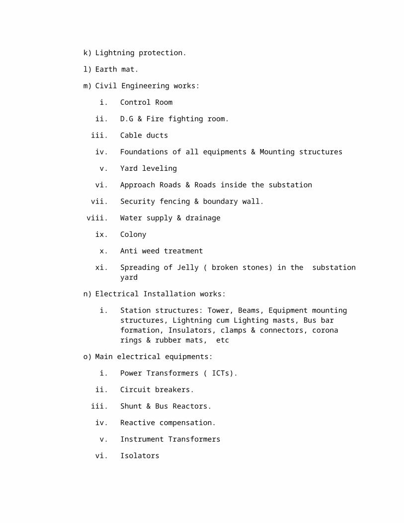
a) Single Bus arrangement:
ADVANTAGES DISADVANTAGES
1. Simple in Design
2. Less Expenditure
1. In case of bus fault or bus bar isolator fault or maintenance Total Substation is out of service.
2. In case of maintenance of transformer circuit breaker the associated transformer has also to be shut-down. Similarly for Line also.
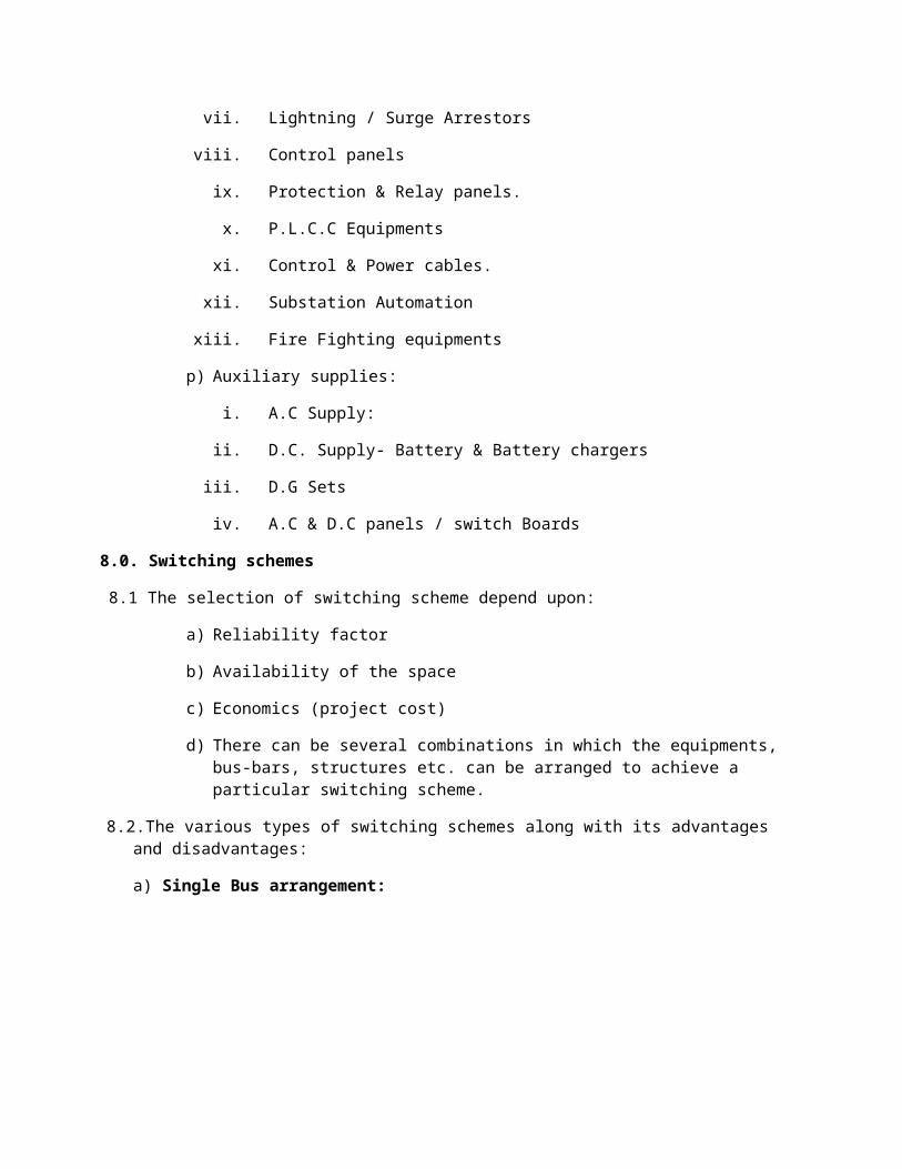
b) Single Bus with bus sectionaliser:
Main Bus is divided into two sections with a Circuit Breaker and isolators in between the adjoining sections. One complete section can be taken out for Maintenance without disturbing the continuity of other section. Even if a fault occurs on one section of the Bus, that faulty section alone will be isolated while the other section continues to be in service. It will be a little more costly with the addition of one isolator and some cases with Circuit breaker, C.Ts and C&R panel
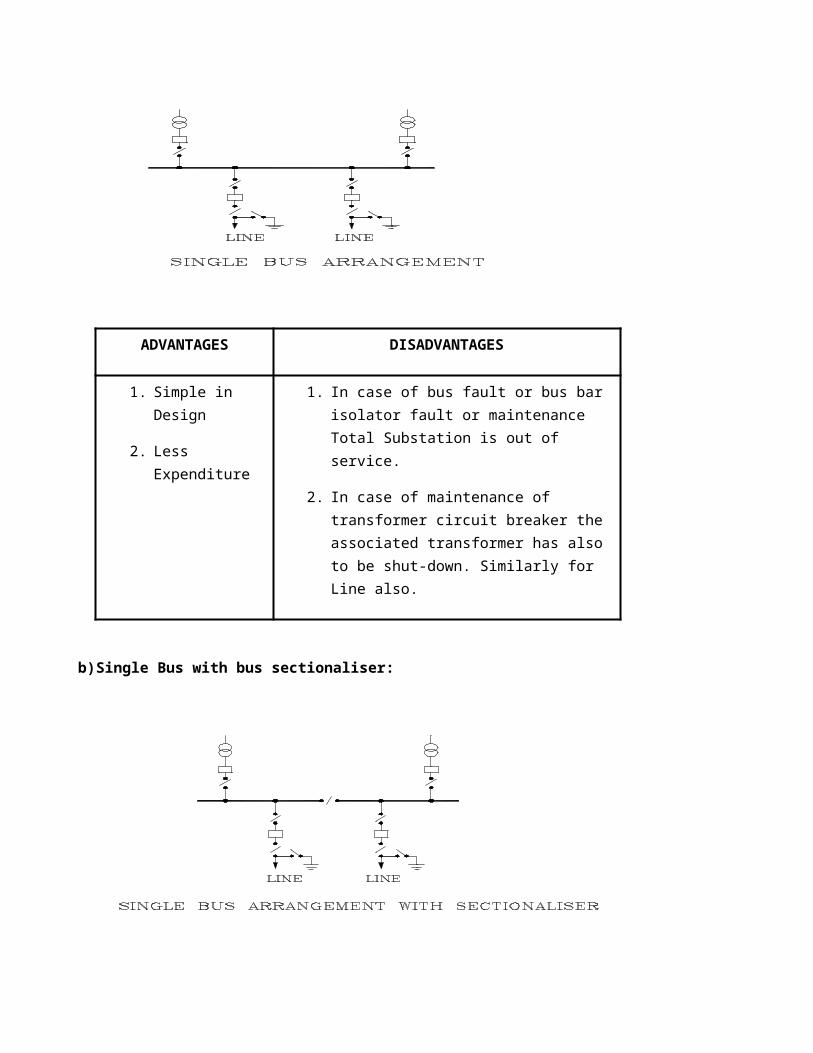
c) SINGLE BUS & TRANSFER BUS SYSTEM:
i. With this arrangement, all the feeders are normally on the Main Bus Bar. If at any time, a Line Circuit Breaker/ Transformer circuit breaker Maintenance is required or break down of Circuit breaker or CTs, that particular feeder/ transformer , can be transferred on to the Transfer Bus. The feeder protection thus gets transferred to trip Transfer Bus Coupler Breaker. On fault occurrence or maintenance, entire bus becomes de-energized.
ii. Salient features:
Only one Circuit at a time can be transferred on the Transfer Bus.
For Maintenance or on fault occurrence, total Bus becomes dead.
d) DOUBLE BUSBAR:
There are six types of Bus switching schemes double bus bars
i. DOUBLE BUSBAR SYSTEM.
ii. DOUBLE BUS WITH SECTIONALISER SYSTEM.
iii. DOUBLE BUS & TRANSFER BUS SYSTEM.
iv. DOUBLE BUS & TRANSFER BUS WITH SECTIONALISER SYSTEM.
v. ONE & HALF BREAKER SYSTEM
vi. ONE & HALF BREAKER WITH SECTIONALISER SYSTEM
d-i) Double main Bus system ( Bus -1 & Bus-2) & Double main Bus with transfer Bus scheme
19
LinesLines
Lines LinesLines
Main Bus
Transfer Bus
Main Bus1
Main Bus2
Transformer Transformer Transformer Transformer
•MainBuswith Transfer Bus •DoubleMain Bus
Double main bus:
This system has got flexibility of transferring any Circuit to any of the Bus.For Maintenance or on fault occurrence on one Bus, then only that Bus becomes dead, while the other Bus remains in service. For Maintenance of a Circuit Breaker, that particular Circuit has to be taken out of service. To overcome this, an additional bypass isolator is provided as indicated in figure above
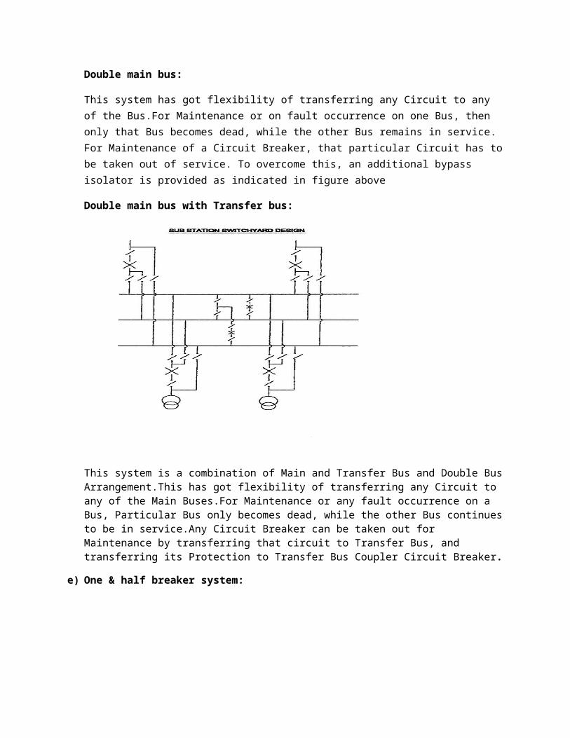
Double main bus with Transfer bus:
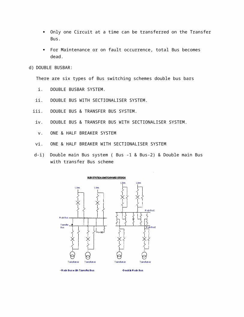
This system is a combination of Main and Transfer Bus and Double Bus Arrangement.This has got flexibility of transferring any Circuit to any of the Main Buses.For Maintenance or any fault occurrence on a Bus, Particular Bus only becomes dead, while the other Bus continues to be in service.Any Circuit Breaker can be taken out for Maintenance by transferring that circuit to Transfer Bus, and transferring its Protection to Transfer Bus Coupler Circuit Breaker.
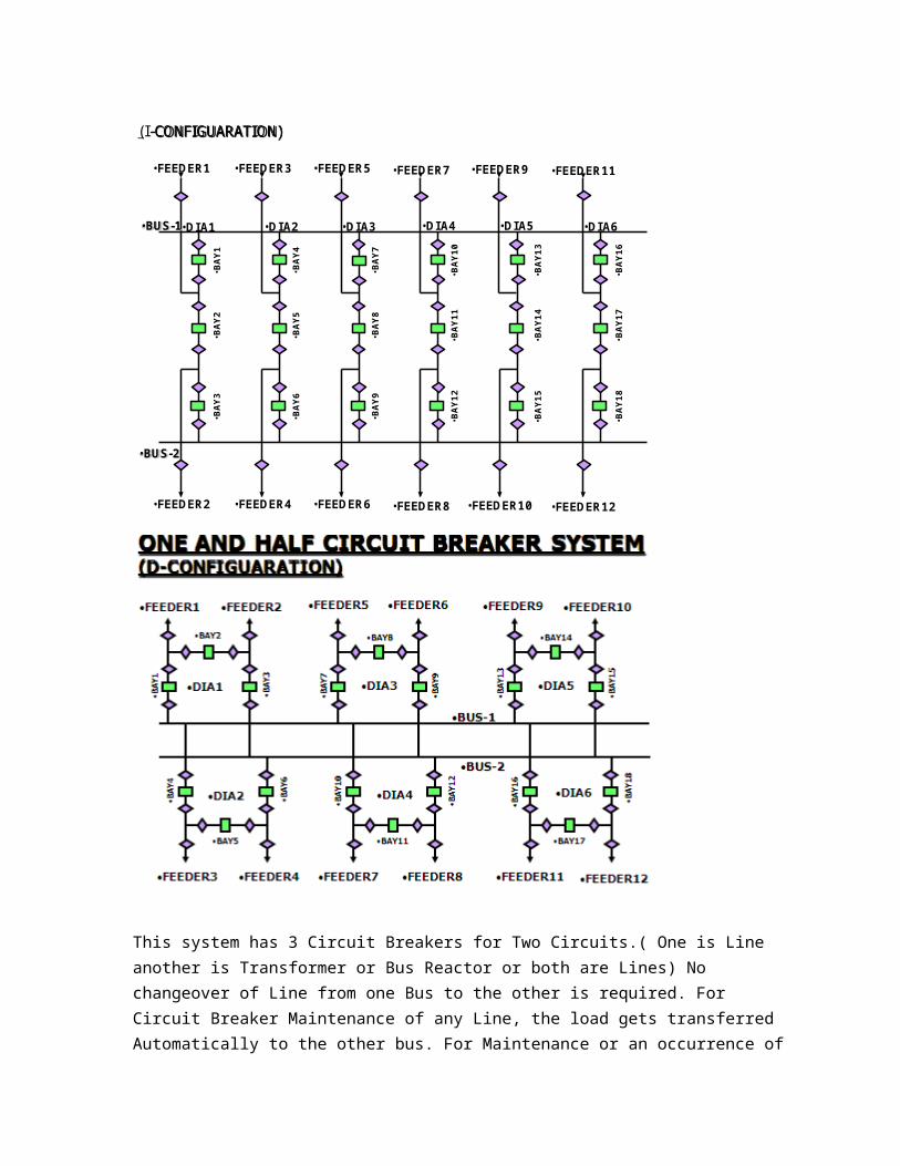
e) One & half breaker system:
(I-CONFIGUARATION)
•FEEDER2 •FEEDER4 •FEEDER6 •FEEDER8 •FEEDER10 •FEEDER12
•FEEDER1 •FEEDER3 •FEEDER5 •FEEDER7 •FEEDER9 •FEEDER11
•BUS-2
•BUS-1
•BAY1
•BAY2
•BAY3
•BAY4
•BAY5
•BAY6
•BAY7
•BAY8
•BAY9
•BAY10
•BAY11
•BAY12
•BAY13
•BAY14
•BAY15
•BAY16
•BAY17
•BAY18
•DIA1 •DIA2 •DIA3 •DIA4 •DIA5 •DIA6
This system has 3 Circuit Breakers for Two Circuits.( One is Line another is Transformer or Bus Reactor or both are Lines) No changeover of Line from one Bus to the other is required. For Circuit Breaker Maintenance of any Line, the load gets transferred Automatically to the other bus. For Maintenance or an occurrence of a Bus fault, all the interconnections will be on healthy bus and no disturbance to the Circuits. Even if both Buses become dead, Circuits can still be in service through the Tie Circuit Breaker.This has got many such advantages to maintain the system stability.
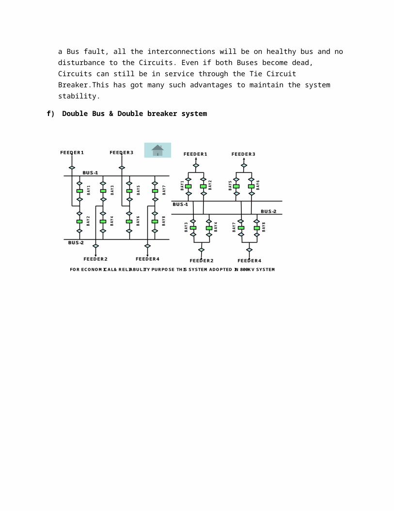
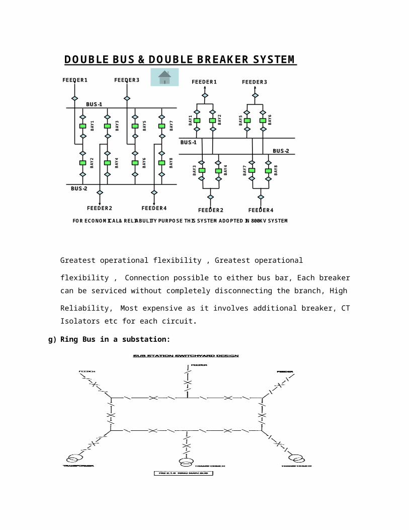
f) Double Bus & Double breaker system
FEEDER1
BAY
1
BAY
2
BAY
3
BAY
4
FEEDER2
FEEDER3
BAY
5
BAY
6
BAY
7
BAY
8
FEEDER4
FEEDER1
BUS-2
BUS-1
BAY
1B
AY2
BUS-2BUS-1
FEEDER2
BAY
3B
AY4
FEEDER3
BAY
5B
AY6
BAY
7B
AY8
FEEDER4
FOR ECONOMICAL& RELIABULITY PURPOSE THIS SYSTEM ADOPTED IN 800KV SYSTEM
DOUBLE BUS & DOUBLE BREAKER SYSTEM
FEEDER1
BAY
1
BAY
2
BAY
3
BAY
4FEEDER2
FEEDER3
BAY
5
BAY
6
BAY
7
BAY
8
FEEDER4
FEEDER1
BUS-2
BUS-1
BAY
1B
AY2
BUS-2BUS-1
FEEDER2
BAY
3B
AY4
FEEDER3
BAY
5B
AY6
BAY
7B
AY8
FEEDER4
FOR ECONOMICAL& RELIABULITY PURPOSE THIS SYSTEM ADOPTED IN 800KV SYSTEM
Greatest operational flexibility , Greatest operational flexibility , Connection possible to either bus
bar, Each breaker can be serviced without completely disconnecting the branch, High Reliability, Most expensive as it involves additional breaker, CT Isolators etc for each circuit.
g) Ring Bus in a substation:
Flexibility for breaker maintenance, Each breaker removable without disconnecting load, Only
one breaker needed per branch, Each branch connected to network by two breakers, All change-over switching done with circuit-breakers & hence flexible.
9.0. Bus bar:
a) Type of Bus bars – Strung Bus/Flexible Bus and Rigid Tubular Bus
b) Strung Bus: The various Types of conductors used for Strung Bus are
i. All Aluminum conductor (AAC)
ii. All Aluminum alloy conductor (AAAC)
iii. Aluminum conductor with aluminum alloy reinforced (ACAR)
iv. Aluminum conductor with steel reinforced (ACSR)
c) Rigid tubular conductors are also used in substations, which are more advantageous than the flexible conductors
d) Sizes of Bus Bar
The important factors for selection of the conductor sizes in a sub-station are,
i. Normal current carrying capability
ii. Short circuit heating with stand capability
iii. Surface gradient
iv. Corona free performance
10.0 Electrical safety clearances:
a)The various clearances which need to be defined.
i. Phase-to-earth clearance.
ii. Phase-to-phase clearance.
iii. Sectional clearance.
iv. Ground clearance.
v. Equipment to equipment spacing
b) The electrical and safety clearances to be adopted in substation are governed by following parameters.
i. Basic Impulse Insulation levels (BIL).
ii. Basic Switching Impulse level (BSL).
iii. IE Rules.
iv. Allowances in tolerance in dimensions of structural work.
v. Safety margins for unforeseen errors
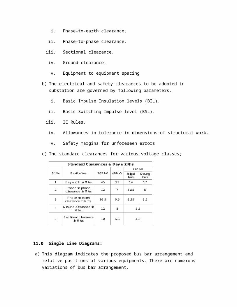
c) The standard clearances for various voltage classes;
Standard Clearances & Bay widths
Sl No Particulars 765 kV 400 kV220 kV
Rigid bus
Strung bus
1 Bay width in Mtrs 45 27 14 17
2 Phase to phase clearance in Mtrs 12 7 3.65 5
3 Phase to earth clearance in Mtrs. 10.5 6.5 3.35 3.5
4 Ground clearance in Mtrs. 12 8 5.5
5 Sectional clearance in Mtrs 10 6.5 4.3
11.0 Single Line Diagrams:
a) This diagram indicates the proposed bus bar arrangement and relative positions of various equipments. There are numerous variations of bus bar arrangement.
b) The choice of a particular arrangement depends on various factors viz. System voltage, position of the substation in the system, flexibility, expected reliability of power supply and cost.
c) The following technical consideration must be borne in mind while deciding upon any one arrangement.
i. Simplicity is the key note of a dependable system
ii. Maintenance should be easy with minimum interruption of supply
iii. Safety to the operating personnel
iv. Alternative arrangement should be available in the event of an outage on any of the equipments or sections of sub station
v. The layout should not hinder for expansion and/or augmentation at a later date, to meet the future load growth
vi. The installation should be as economical as possible keeping in view of the requirements and continuity of supply
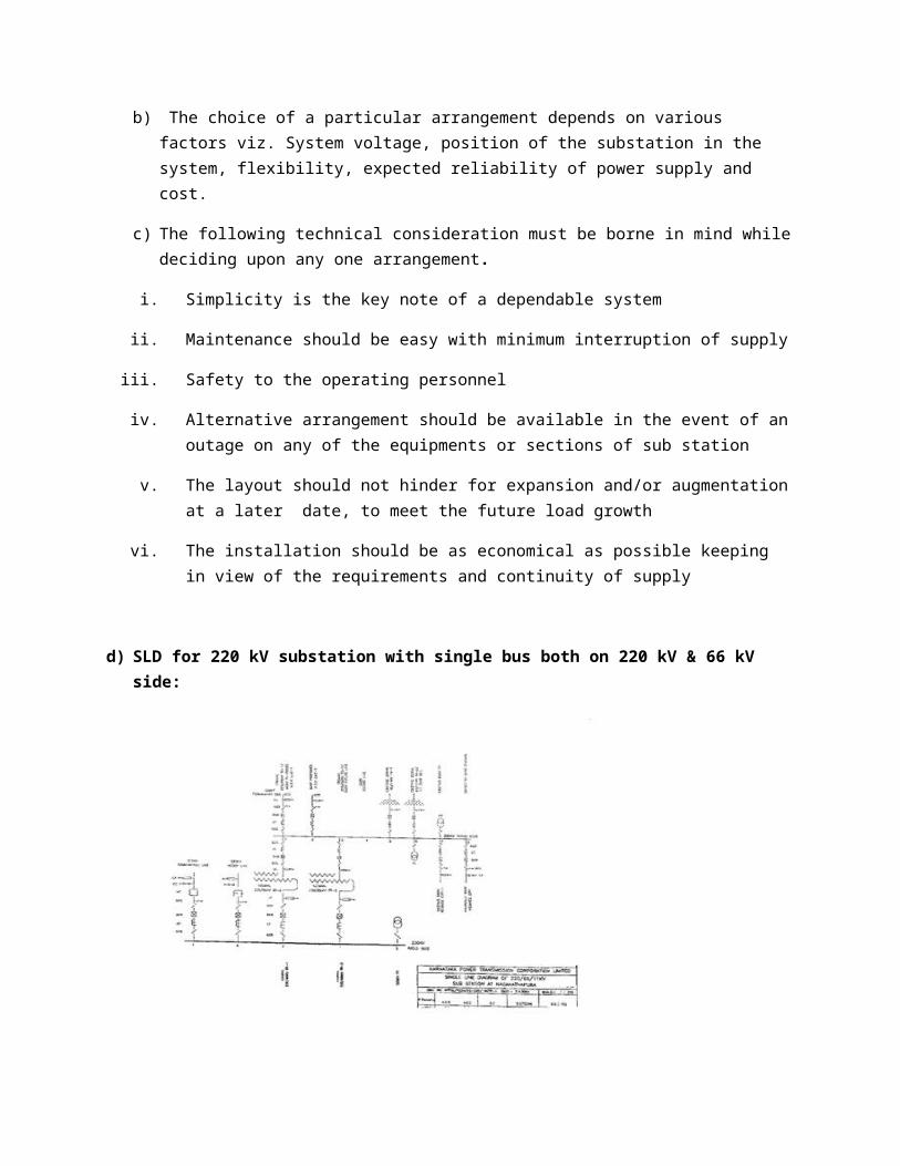
d) SLD for 220 kV substation with single bus both on 220 kV & 66 kV side:
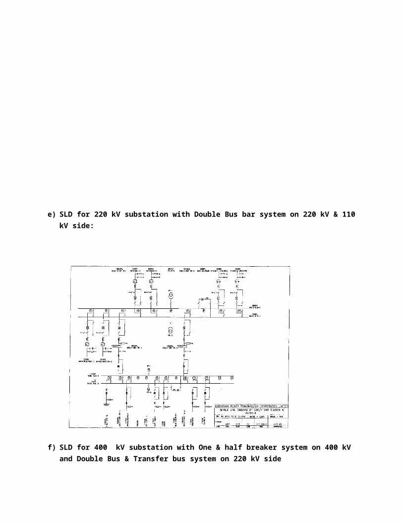
e) SLD for 220 kV substation with Double Bus bar system on 220 kV & 110 kV side:
68
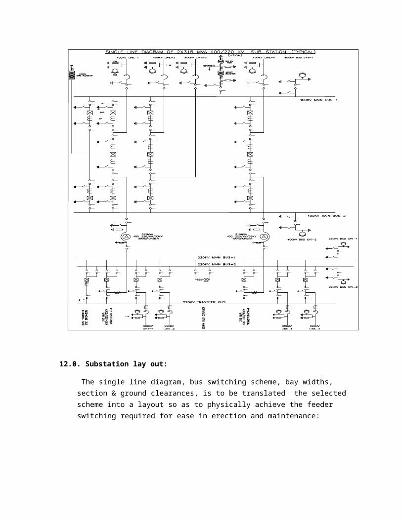
f) SLD for 400 kV substation with One & half breaker system on 400 kV and Double Bus & Transfer bus system on 220 kV side
12.0. Substation lay out:
The single line diagram, bus switching scheme, bay widths, section & ground clearances, is to be translated the selected scheme into a layout so as to physically achieve the feeder switching required for ease in erection and maintenance:
81
13.0 INSULATION – CO-ORDINATION :
a) Insulation coordination is the total of all measures taken to restrict flash over or break down of the insulation caused by over voltages at places with in an installation at which the resulting damage is as slight as possible. This is achieved by using lightning arresters to limit over voltages.
b) The equipments are also to be designed to withstand lightning and switching surges. The nominal lightning impulse withstand voltage and power frequency withstand voltage for various voltage classes are as follows:
c) LIGHTNING PROTECTION:
In H.V.& EHV substations, the protection from the lightning is done either by shield wire or lightning mast (high lattice structure with a spike on top) and sometimes combinations of both depending upon type of layout of substation.
i. Shield wire
Shield wire lightning protection system will be generally used in smaller sub stations of Lower voltage class, where number of bays are less, area of the substation is small. & height of the main structures are of normal height. The major disadvantage of shield wire type lightning protection is, that it causes short circuit in the substation or may even damage the costly equipments in case of its failure (snapping ).
d) Lightning masts (LM)
This type of protection will be generally used in large, extra high voltage sub stations where number of bays are more. It has the following advantages,
i. It reduces the height of main structures, as peaks for shield wire are not required
ii. It removes the possibility of any back flashover with the near by equipments/structure, etc.during discharge of
iii. lightning strokes
iv. Provides facility for holding the lightning fixtures in the substation for illumination purposes.
v. Aesthetic look.
14.0 Earth mat requirement:
a) The main objective of earthing system in the substation is,
i. To ensure that a person in the vicinity of substation is not exposed to danger of electrical shock
ii. To provide easy path for fault currents into earth under fault condition without affecting the continuity of service

iii. Hence intentional earthing system is created by laying earthing rod of mild steel in the soil of substation area. All equipments/structures which are not meant to carry the currents for normal operating system are connected with main earth mat
iv. The earthing system in a substation serves the following
Protects the life and property from over-voltage
To limit step & touch potential to the working staff in substation
Provides low impedance path to fault currents to ensure prompt and consistent operation of protective device
Stabilizes the circuit potentials with respect to ground and limit the overall potential rise
Keeps the maximum voltage gradients within safe limit during ground fault condition inside and around substation
b) The main earth mat shall be laid horizontally at a regular spacing in both X & Y direction based upon soil resistivity value and short circuit value at substation. The main earth mat shall be designed to limit the following;
i. Touch Potential – The potential difference between two points, one on the ground where a man may stand and any other point which can be simultaneously touched by either hand.
ii. Step Potential – The potential difference between any two points on ground surface which can be simultaneously touched by feet.
iii. Maximum ground mat resistance shall be less than 1.0 ohm for substations of 220kV class and below, and shall be 0.5 ohms for 400kV and above voltage class.
iv. The earth rods shall be capable of with standing short circuit current for specified period.
v. For I KA SC current for 1 second the minimum cross sectional area of M.S. Rod / Flat shall be 12.16 sq mm with welded joints.
15.0 . INSULATORS:
a) Types of insulators : Disc type & Post type :
i. Disc type
ii. Post type : Pedestal post or stacking type and Solid core type
The design considerations are,
The phase to earth clearance which determines the height
Insulation level
Power frequency withstand level
Mechanical strength i.e., mainly cantilever strength
Minimum creepage dimensions
16.0 Illumination:
The indoor & out door areas of sub station are to be properly illuminated. The minimum lux levels to be maintained in the different areas are follows.