E.George, V. Sabel'nikov, P. Magre - West-East High Speed Flow
11
WEST-EAST HIGH SPEED FLOW FIELD CONFERENCE 19-22, November 2007 Moscow, Russia SELF-IGNITION OF ETHYLENE-HYDROGEN MIXTURES IN UNSTEADY THERMAL CHOCKING CONDITIONS: NUMERICAL UNSTEADY RANS INVESTIGATIONS E.George * , V. Sabel’nikov ** and P. Magre ** * Gaz de France, Research and Development Division, 361, av. du Pr´ esident Wilson, 93211 Saint Denis La Plaine Cedex, France, e-mail: [email protected] ** ONERA, Fundamental and Applied Energetics Department, Chemin de la Huni` ere, 91761 Palaiseau Cedex, e-mails: [email protected] , [email protected] Key words: supersonic combustion, self-ignition, turbulence, micromixing, LES Abstract. The paper deals with the self-ignition of ethylene-hydrogen mixture jet in vitiated confined supersonic air stream. Self-ignition in this configuration was studied by one of the authors in ONERA’s LAERTE test facility. Two self-ignition modes were described in the experiments - weak and abrupt. Unsteady RANS equations are applied here to simulate the abrupt self-ignition mode. Computations reveal the flow oscillations process driven by interaction between the thermal choking and fuel-air mixing process. 1 INTRODUCTION Supersonic combustion is a problem of a great fundamental and practical interest, since supersonic ramjets (scramjets) are promising for future airbreathing systems. The further development of scramjets can be significantly aided by the use of CFD. The phenomenon of self-ignition in turbulent supersonic flows is one of the most important for better under- standing and ability to predict the complex thermo-fluid dynamics of supersonic reacting flows. The experimental studies of self-ignition in turbulent supersonic flows are sparse. Self-ignition of sonic hydrogen jet in a free coflow supersonic (M = 2) vitiated air was investigated in 1 . Self-ignition of supersonic (M = 2) hydrogen, methane-hydrogen, and ethylene-hydrogen jets in vitiated confined supersonic stream was studied in ONERA’s LAERTE test facility by one of the authors 2,3,4 (methane-hydrogen self-ignition data are reproduced in the PhD thesis 5 ). Two self-ignition modes were described in 2 - weak and abrupt. Weak mode is characterized by slowly increasing heat release in pure supersonic flows. Abrupt mode, observed in 2 for ethylene-hydrogen mixtures, manifests by brusque heat release and pressure rise, thermal choking and local subsonic zones appearence. The data collected in the combustor were intended to be used for validation of CFD models, and LES in particular. LAERTE data were already used to validate LES and stationary RANS modelings to simulate self-ignition for hydrogen and methane-hyrogen 1
Transcript of E.George, V. Sabel'nikov, P. Magre - West-East High Speed Flow
WEST-EAST HIGH SPEED FLOW FIELD CONFERENCE19-22, November 2007
Moscow, Russia
SELF-IGNITION OF ETHYLENE-HYDROGEN MIXTURESIN UNSTEADY THERMAL CHOCKING CONDITIONS:NUMERICAL UNSTEADY RANS INVESTIGATIONS
E.George∗, V. Sabel’nikov∗∗ and P. Magre∗∗
∗Gaz de France, Research and Development Division, 361, av. du President Wilson, 93211Saint Denis La Plaine Cedex, France, e-mail: [email protected]
∗∗ONERA, Fundamental and Applied Energetics Department, Chemin de la Huniere, 91761Palaiseau Cedex, e-mails: [email protected] , [email protected]
Key words: supersonic combustion, self-ignition, turbulence, micromixing, LES
Abstract. The paper deals with the self-ignition of ethylene-hydrogen mixture jet invitiated confined supersonic air stream. Self-ignition in this configuration was studiedby one of the authors in ONERA’s LAERTE test facility. Two self-ignition modes weredescribed in the experiments - weak and abrupt. Unsteady RANS equations are appliedhere to simulate the abrupt self-ignition mode. Computations reveal the flow oscillationsprocess driven by interaction between the thermal choking and fuel-air mixing process.
1 INTRODUCTION
Supersonic combustion is a problem of a great fundamental and practical interest, sincesupersonic ramjets (scramjets) are promising for future airbreathing systems. The furtherdevelopment of scramjets can be significantly aided by the use of CFD. The phenomenonof self-ignition in turbulent supersonic flows is one of the most important for better under-standing and ability to predict the complex thermo-fluid dynamics of supersonic reactingflows. The experimental studies of self-ignition in turbulent supersonic flows are sparse.Self-ignition of sonic hydrogen jet in a free coflow supersonic (M = 2) vitiated air wasinvestigated in1. Self-ignition of supersonic (M = 2) hydrogen, methane-hydrogen, andethylene-hydrogen jets in vitiated confined supersonic stream was studied in ONERA’sLAERTE test facility by one of the authors2,3,4(methane-hydrogen self-ignition data arereproduced in the PhD thesis5). Two self-ignition modes were described in2 - weak andabrupt. Weak mode is characterized by slowly increasing heat release in pure supersonicflows. Abrupt mode, observed in2for ethylene-hydrogen mixtures, manifests by brusqueheat release and pressure rise, thermal choking and local subsonic zones appearence.
The data collected in the combustor were intended to be used for validation of CFDmodels, and LES in particular. LAERTE data were already used to validate LES andstationary RANS modelings to simulate self-ignition for hydrogen and methane-hyrogen
1

E. George et al., Numerical Unsteady RANS Investigations
mixtures in5,6, respectively. Abrupt self-ignition mode offers greater difficulties for nu-merical computations, and it was not yet considered. This paper is the first attempt tosimulate the abrupt mode of self-ignition. For the sake of acceptable computational cost,unsteady RANS modeling, without taking into account turbulence-chemistry interaction,is applied.
2 LAERTE EXPERIMENTAL SET-UP
The LAERTE test facility consists of the following major components: the flame pre-heater, supersonic nozzle, the optically accessible combustor, hydrogen, hydrocarbons,and air flow loops, combustion products exhaust system. The combustor configuration isshown schematically in Figure 1. The combustor consisted of two segments: 1) a 45× 45
Figure 1: Scheme of the LAERTE experimental test facility
.
mm2 constant cross-section area duct of 370 mm long; 2) a slightly divergent duct of 500mm long with 1.15 degree expansion along the top and bottom walls (i.e. overall 2.3degree expansion). The combustor was connected directly to a supersonic Mach 2 nozzle.The air is preheated first up to 850K in a primary heat exchanger, and then up to 1850Kin the flame hydrogen-air heater with oxygen replenishment to obtain a test gas with thesame oxygen mole fraction as atmospheric air (0.2095). Water vapors were around 16percent in molar fractions. Air mass rate was typically 650 g/s. Static pressure at thecombustor entrance was 0.08 MPa. A water-cooled axisymetrical supersonic fuel injectorof internal diameter d = 6 mm (external diameter is 10 mm) was installed along the axisof the nozzle. Its exit section was at x0 = 33 cm downstream of combustor entrance. Su-personic (Mach 2) fuel jets were adapted to the static pressure at the combustor entrance.Optical access was obtained via silica windows that can be mounted in the side platesof the test section to get the information for the three domains: 6 < (x − x0)/d < 15,26 < (x − x0)/d < 34, and 37 < (x − x0)/d < 43. More details on the combustor andtest facility can be found elsewhere2,4. Pressure transducers (of overall number 80) weredistributed along the top and bottom walls of combustor to measure the pressure distri-bution along the combustor. PLIF images of OH radicals were done to detect the flame
2

E. George et al., Numerical Unsteady RANS Investigations
structure. The molar fraction of ethylene in C2H4 − H2 mixture was in the range 0-50percent. Operating conditions are summarized in Table 1.
Air H2 26% C2H4 - 74% H2 50% C2H4 - 50% H2
molar fractions molar fractionsMach number 2 2 2 2
Static pressure (MPa) 0.08 0.08 0.08 0.08Total temperature (K) 1850 300 300 300Static temperature (K) 1200 160 160 160
mass flow rate (g/s) 650 6,2 12.8 (C2H4) - 2.6 (H2) 16.2 (C2H4) - 1.2 (H2)velocity (m/s) 1336 1970 950 730
Table 1: Experimental conditions
Weak mode of self-ignition was observed for 26 percent C2H4 - 74 percent H2 mixture,and abrupt mode was observed for 50 percent C2H4 - 50 percent H2 mixture. URANSmodeling (described in section 4) is used to simulate the abrupt mode.
3 EXPERIMENTAL RESULTS. PRESSURE DISTRIBUTIONS
Because of hostile environment of the high-temperature reacting supersonic flow, theonly parameter measured systematically is the mean wall pressure distribution along thecombustor. To determine the location where the ignition starts, the wall pressure distri-butions for both a non-reacting case (using nitrogen instead of fuel) and a reacting caseare compared. The self-ignition delay length is determined as the distance between theinjector exit section and the location where reacting pressure distribution levels starts toincrease in comparison with non-reacting one.The reference case is obtained with pure hydrogen injection. Mean wall pressure (nor-malized by plenum pressure Pt) distributions for H2 injection along with N2 injection(without combustion) are presented in Figure 2 (a). The estimated self-ignition delaylength is about 15 cm. One can conclude that the self-ignition and following combustionof pure hydrogen is characterized by the moderate rate of wall pressure rise due to a slowlyincreasing heat release. Here after, to distinguish this scenario of self-ignition from quali-tatively different regimes of self-ignition obtained for the mixture C2H4 - H2 when C2H4
mole fraction exceed 26 percent, it will be called weak combustion mode. The pressureincrease in the test section is of the order of 0.3 bar. The flow remains supersonic overthe whole test section. Addition of ethylene to hydrogen results in chemically less activefuels. In the range from 0 to 26 percent C2H4 in mole fraction the self-ignition delaylength continuously increases, but the character of the mean wall pressure distributionalong the combustor does not change. Figure 2 (b) shows mean wall pressure distributionfor 26 percent C2H4 - 74 percent H2 (molar fraction) mixture injection to illustrate theabove said. Estimated self-ignition length is about 25 cm.
3

E. George et al., Numerical Unsteady RANS Investigations
Figure 2: Weak mode of self-ignition. Normalized wall mean pressure distribution for pure hydrogen (a),for 26 percent ethylene - 74 percent hydrogen mixture (b)
.
Figure 3: Abrupt mode of self-ignition. Normalized wall mean pressure distribution for 50 percentethylene - 50 percent hydrogen mixture
.
The nature of wall pressure distribution changes qualitatively once the content of C2H4
exceeds 29 percent - brusque rise of pressure appears in the diverging part of combus-tor. Figure 3 shows mean wall pressure distribution for 50 percent C2H4 - 50 percent H2
mixture injection. This combustion regime was called in2,6,7 as abrupt combustion mode.Estimation based on 1D approach7 revealed that self-ignition in this case was followed bythe thermal choking. Figure 4 (taken from7) shows the calculated Mach number distribu-tion along the combustor. The local subsonic region appears between 0.4 m< (x− x0) <0.63 m. The flow first decelerates to sonic velocities in precombustion shock, then sub-sonic flow accelerates due to heat release, passes through a thermal throat (x− x0 = 0.63m) and becomes supersonic. Three conclusions can be done here. First, because of up-
4

E. George et al., Numerical Unsteady RANS Investigations
Figure 4: Abrupt mode of self-ignition. Mach number axial distribution for 50 percent ethylene - 50percent hydrogen mixture
.
stream influence of pressure rise and impact of precombustion shocks on ignition process,the mean wall pressure distribution for abrupt combustion mode cannot be used for de-termination of the self-ignition delay length for abrupt combustion mode. Second, eventhough the flow is supersonic at the entrance and the combustor exit, pressure oscillationscan propagate through the local subsonic zone. As a consequence, the combustor may besusceptible to combustion instabilities due to acoustic-convective interactions between thefuel-air mixing and heat release zones. Similar consideration are presented in8. Pressurefluctuations generated in the heat release zone propagate upstream and cause the equiv-alence ratio and self-ignition delay length fluctuations. Third, flow oscillations can bedriven also by heat release fluctuations that provoke the unsteadiness of thermal chockinglocation.Further in this paper we concentrate on the numerical simulation of the unsteady flowfor abrupt combustion mode. To reduce the computational cost, the numerical model isbased on unsteady RANS equations neglecting turbulence-chemistry interaction9.
4 UNSTEADY RANS MODELING
4.1 URANS Equations
Unsteady RANS equations are used for numerical simulations. They can be expressedin the following Cartesian tensor form (index notation for tensors with the summationconvention is used):
5

E. George et al., Numerical Unsteady RANS Investigations
∂ρ
∂t= −∂ρuk
∂xk
, (1)
∂ρuk
∂t= − ∂
∂xk
[ρukul + ρδkl − τkl] , (2)
∂ρE
∂t= − ∂
∂xk
[(ρE + p)uk + qk − ulτ kl] , (3)
∂ρYk
∂t= − ∂
∂xk
[ρYkuk − θk,l] + ωk , (4)
where overbars and tildes denote Reynolds and Favre averaged variables (f = ρf/ρ, forany variable f), respectively. ρ, uk, p, E, τkl, qk, and θk,l represent the density, veloc-ity components, pressure, specific total energy, stress tensor, heat and diffusion fluxes,respectively. The unclosed terms are modelled using eddy diffusivity model:
τkl = −2ρνt[Skl −1
3Skkδkl] , (5)
qk = −ρνtCp/Prt∂T
∂xk
− ρνt
Sct
∂Tl
∂xk
hl , (6)
θk,l = ρνt/Sct∂Yk
∂xl
, (7)
where Sij is the Favre-averaged rate-of-strain tensor, hl is the enthalpy of the lth species.Turbulent viscosity νt is calculated from k − l turbulence model; the turbulent Prandtland Schmidt numbers are 0.9 and 0.7, respectively.The gas mixture pressure is determined from the equation of state:
p = ρR0T
Ns∑k=1
Yk
Wk
, (8)
(9)
where R0 and Wk are the universal gas constant and the molecular weight for kth species,Ns is the total number of species. We neglect further by turbulence-chemistry interaction,as a consequence the mean chemical source term ωk is calculated using mean ρ, Yk andT .
4.2 Computational Details
2D axisymetric simulations were performed with the CFD code CEDRE developedat ONERA. The equivalent axisymmetric combustor with the cross-area section axialdistribution of real combustor was used, to keep the same air/fuel mass flow ratios. The
6

E. George et al., Numerical Unsteady RANS Investigations
governing equations are solved using a finite volume scheme that is nominally second orderexplicit Runge-Kutta integration scheme (second order in time and space). Numericalscheme used in CEDRE is a shock capturing scheme that is well adapted to supersonicflows10,11. For this scheme, in explicit formulation, stability, and accuracy are obtainedat CFL ≈ 1.
The present finite rate chemistry model includes 10 species (C2H4, O2, H2, H2O, OH,H, O, CO, CO2, and N2) and 10 elementary reaction steps. The kinetic data are takenfrom12. Chemistry is treated implicitly in CEDRE.The computational domain comprises the space between the injector exit section and thecombustor exit located at 837 mm downstream of injector exit. The grid of 10.000 cells(500×200) was generated by GMSH. The grids points were clustered near the combustorwalls and in the supersonic mixing layer formed by the fuel jets and air coflow. A gridindependence study was performed as part of the validation procedure. Two differentgrid resolutions with 10.000 and 15.000 (500×300) nodes agree well with each other.Calculations were performed with ONERA’s vectorial computer NEC SX-8.
All boundary conditions are specified to closely match the experiments. Supersonicinflow and outflow conditions are imposed. The logarithmic law of the wall, Reynoldsanalogy for heat transfer coefficient are applied in turbulent boundary layers at combustorwalls. Computations are started from the velocity field corresponding to the main non-reactive air stream, with imposed stagnation temperature and stagnation pressure atthe inflow boundaries. The turbulence intensity at the inflow section is taken equal to 5percent for of air and fuel streams. Time integration was carried out with a CFL ≈ 1. Thissmall value of CFL number is mainly dictated by gasdynamic structure of supersonic flow,as was explained above. Calculations simulate the physical time duration 70 ms (residencetime in the combustor is about 1 ms).
5 RESULTS AND DISCUSSION
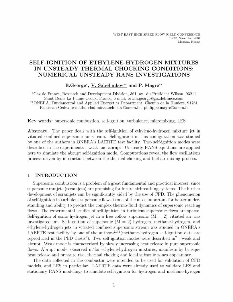
Figure 5 shows the mean wall pressure distributions along the combustor at 7 differentevolution times. Few observations are noted here. First, transient period from initialnonreactive case to stationary state lasts a long time - about 35 ms (35 residence time incombustor). Second, brusque pressure rise appears between 20 and 22 ms; pressure fieldbecomes essentially non-steady. Later on 25 ms pressure wave lifts and goes downstreamwith amplitude 2.6-3 cm. Third, the self-ignition with URANS modeling is premature thatis explained by neglecting turbulence-chemistry interaction. Forth, the maximum pressurerise is in good agreement with experiment. The power spectral density of pressure wasdetermined from pressure signal (between 30 and 70 ms) and it is shown in Figure 6.Despite on important statistical fluctuations, one can see the spectral peak of 580 Hz,that corresponds 1.72 ms oscillation period. Figure 7 shows instantaneous snapshot ofpressure field for intermediate time t = 25 ms of transient period. One can see severalbifurcated shocks that lead to the formation of Mach structure. Shock train region isformed in which pressure build-up develops. The head shock appears at (x− x0) ≈ 31.5
7

E. George et al., Numerical Unsteady RANS Investigations
Figure 5: Mean wall pressure distributions for different instants, arrow points in the direction of the timeevolution
.
Figure 6: Power spectral density of pressure for thermal choking (arbitrary units)
.
cm.
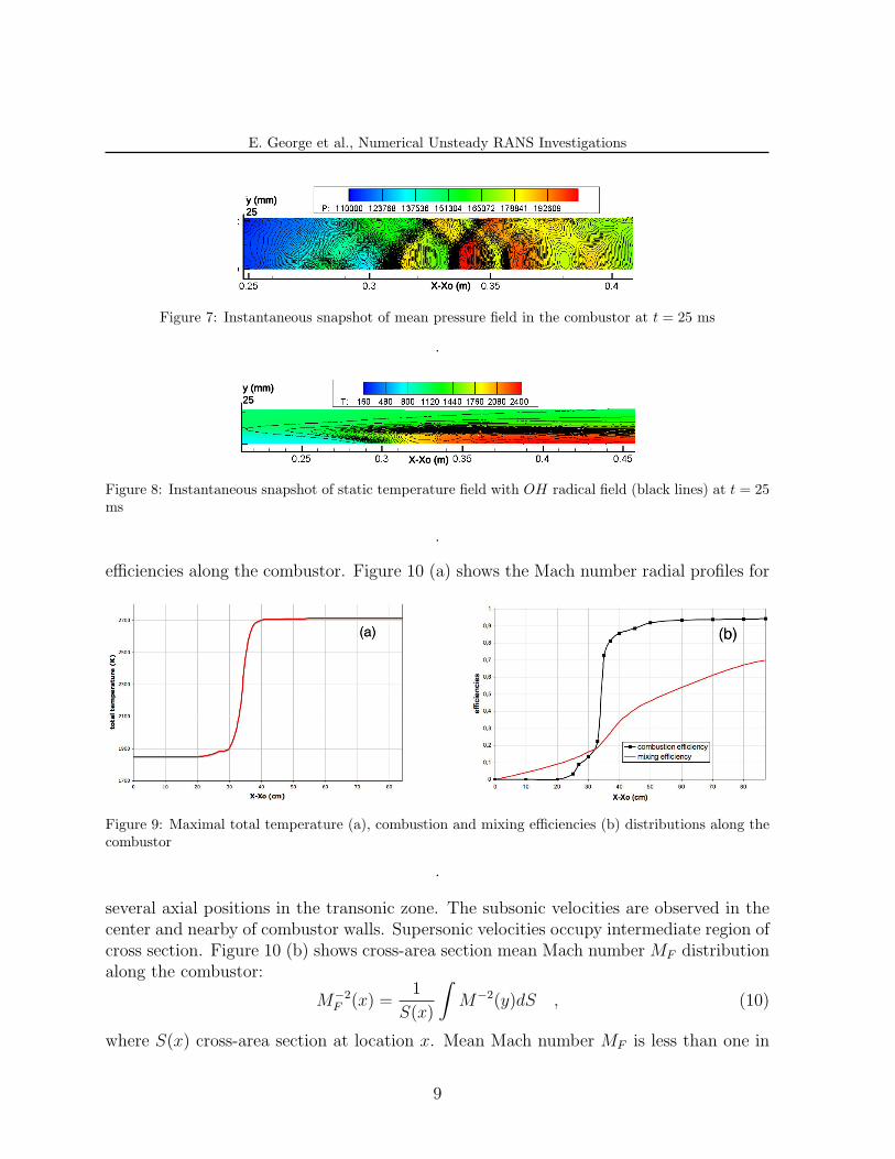
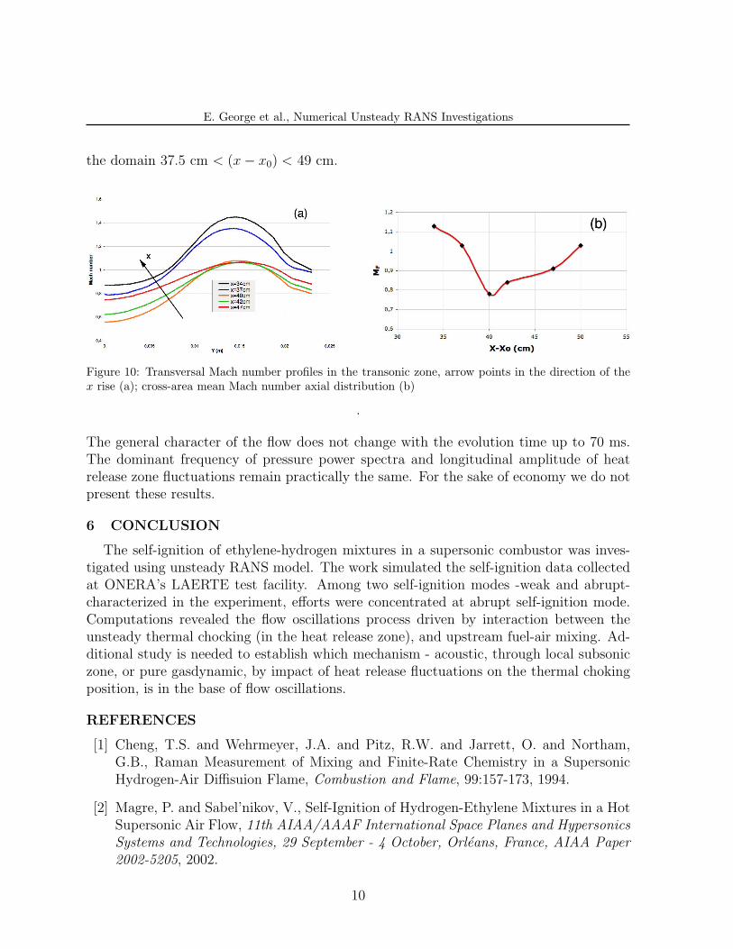
Figure 8 shows instantaneous snapshot of static temperature and radical OH. Theformation of OH starts at (x−x0) ≈ 21 cm. The temperature rise is sharp and takes placeat (x−x0) ≈ 34 cm. Figure 9 (a) shows the maximal total temperature distribution alongthe combustor. Practically overall heat release occurs at 5 cm length. The combustion ismixing controlled. It is illustrated in Figure 9 (b) that shows the mixing and combustion
8
E. George et al., Numerical Unsteady RANS Investigations
y (mm)25
X-Xo (m)
Figure 7: Instantaneous snapshot of mean pressure field in the combustor at t = 25 ms
.
y (mm)25
X-Xo (m)
Figure 8: Instantaneous snapshot of static temperature field with OH radical field (black lines) at t = 25ms
.
efficiencies along the combustor. Figure 10 (a) shows the Mach number radial profiles for
Figure 9: Maximal total temperature (a), combustion and mixing efficiencies (b) distributions along thecombustor
.
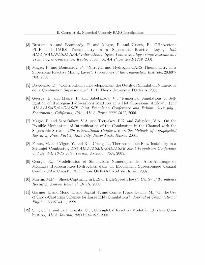
several axial positions in the transonic zone. The subsonic velocities are observed in thecenter and nearby of combustor walls. Supersonic velocities occupy intermediate region ofcross section. Figure 10 (b) shows cross-area section mean Mach number MF distributionalong the combustor:
M−2F (x) =
1
S(x)
∫M−2(y)dS , (10)
where S(x) cross-area section at location x. Mean Mach number MF is less than one in
9
E. George et al., Numerical Unsteady RANS Investigations
the domain 37.5 cm < (x− x0) < 49 cm.
Figure 10: Transversal Mach number profiles in the transonic zone, arrow points in the direction of thex rise (a); cross-area mean Mach number axial distribution (b)
.
The general character of the flow does not change with the evolution time up to 70 ms.The dominant frequency of pressure power spectra and longitudinal amplitude of heatrelease zone fluctuations remain practically the same. For the sake of economy we do notpresent these results.
6 CONCLUSION
The self-ignition of ethylene-hydrogen mixtures in a supersonic combustor was inves-tigated using unsteady RANS model. The work simulated the self-ignition data collectedat ONERA’s LAERTE test facility. Among two self-ignition modes -weak and abrupt-characterized in the experiment, efforts were concentrated at abrupt self-ignition mode.Computations revealed the flow oscillations process driven by interaction between theunsteady thermal chocking (in the heat release zone), and upstream fuel-air mixing. Ad-ditional study is needed to establish which mechanism - acoustic, through local subsoniczone, or pure gasdynamic, by impact of heat release fluctuations on the thermal chokingposition, is in the base of flow oscillations.
REFERENCES
[1] Cheng, T.S. and Wehrmeyer, J.A. and Pitz, R.W. and Jarrett, O. and Northam,G.B., Raman Measurement of Mixing and Finite-Rate Chemistry in a SupersonicHydrogen-Air Diffisuion Flame, Combustion and Flame, 99:157-173, 1994.
[2] Magre, P. and Sabel’nikov, V., Self-Ignition of Hydrogen-Ethylene Mixtures in a HotSupersonic Air Flow, 11th AIAA/AAAF International Space Planes and HypersonicsSystems and Technologies, 29 September - 4 October, Orleans, France, AIAA Paper2002-5205, 2002.
10
E. George et al., Numerical Unsteady RANS Investigations
[3] Bresson, A. and Bouchardy, P. and Magre, P. and Grisch, F., OH/AcetonePLIF and CARS Thermometry in a Supersonic Reactive Layer, 10thAIAA/NAL/NASDA/ISAS International Space Planes and hypersonic Systems andTechnologies Conference, Kyoto, Japan, AIAA Paper 2001-1759, 2001.
[4] Magre, P. and Bouchardy, P., ”Nitrogen and Hydrogen CARS Thermometry in aSupersonic Reactive Mixing Layer”, Proceedings of the Combustion Institute, 28:697-703, 2000.
[5] Davidenko, D., ”Contribution au Developpement des Outils de Simulation Numeriquede la Combustion Supersonique”, PhD Thesis Universite d’Orleans, 2005.
[6] George, E. and Magre, P. and Sabel’nikov, V., ”Numerical Simulations of Self-Ignition of Hydrogen-Hydrocarbons Mixtures in a Hot Supersonic Airflow”, 42ndAIAA/ASME/SAE/ASEE Joint Propulsion Conference and Exhibit, 9-12 july ,Sacramento, California, USA, AIAA Paper 2006-4611, 2006.
[7] Magre, P. and Sabel’nikov, V.A. and Tretyakov, P.K. and Zabaykin, V.A., On thePossible Mechanisms of Intensification of the Combustion in the Channel with theSupersonic Stream, 12th International Conference on the Methods of AerophysicalResearch, Proc. Part 2, June-July, Novosibirsk, Russia, 2004.
[8] Fuhua, M. and Vigor, Y. and Kuo-Cheng, L., Thermoacoustic Flow Instability in aScramjet Combustor, 41st AIAA/ASME/SAE/ASEE Joint Propulsion Conferenceand Exhibit, 10-13 July, Tucson, Arizona, USA, 2005.
[9] George, E., ”Modelisation et Simulations Numeriques de l’Auto-Allumage deMelanges Hydrocarbures-Hydrogenes dans un Ecoulement Supersonique CoaxialConfine d’Air Chaud”, PhD Thesis ONERA/INSA de Rouen, 2007.
[10] Martin, M.P., ”Shock-Capturing in LES of High-Speed Flows”, Center of TurbulenceResearch, Annual Research Briefs, 2000.
[11] Garnier, E. and Mossi, E. and Sagaut, P. and Comte, P. and Deville, M., ”On the Useof Shock-Capturing Schemes for Large Eddy Simulations”, Journal of ComputationalPhysic, 153:273-311, 1999.
[12] Singh, D.J. and Jachimowski, C.J., Quasiglobal Reaction Model for Ethylene Com-bustion, AIAA Journal, 32(1):213-216, 2001.
11