
Efficiently Combining Water Reuse and Desalination · PDF file · 2016-07-09water...
24
membranes Review Efficiently Combining Water Reuse and Desalination through Forward Osmosis—Reverse Osmosis (FO-RO) Hybrids: A Critical Review Gaetan Blandin 1, *, Arne R.D. Verliefde 2 , Joaquim Comas 1,4 , Ignasi Rodriguez-Roda 1,4 and Pierre Le-Clech 3 1 LEQUIA, Institute of the environment, University of Girona, Campus Montilivi, Girona 17003, Spain; [email protected] (J.C.); [email protected] (I.R.-R.) 2 Department of Applied Analytical and Physical Chemistry, Ghent University, Faculty of Bioscience Engineering, Particle and Interfacial Technology Group (PaInT), Gent 9000, Belgium; [email protected] 3 UNESCO Centre for Membrane Science and Technology, School of Chemical Engineering, The University of New South Wales, Sydney NSW2052, Australia; [email protected] 4 ICRA, Catalan Institute for Water Research, Parc scientific and technologic of the university of Girona, Girona 17003, Spain * Correspondence: [email protected]; Tel.: +34-618-804-214 Academic Editors: Marco Stoller and Javier Miguel Ochando-Pulido Received: 31 May 2016; Accepted: 27 June 2016; Published: 1 July 2016 Abstract: Forward osmosis (FO) is a promising membrane technology to combine seawater desalination and water reuse. More specifically, in a FO-reverse osmosis (RO) hybrid process, high quality water recovered from the wastewater stream is used to dilute seawater before RO treatment. As such, lower desalination energy needs and/or water augmentation can be obtained while delivering safe water for direct potable reuse thanks to the double dense membrane barrier protection. Typically, FO-RO hybrid can be a credible alternative to new desalination facilities or to implementation of stand-alone water reuse schemes. However, apart from the societal (public perception of water reuse for potable application) and water management challenges (proximity of wastewater and desalination plants), FO-RO hybrid has to overcome technical limitation such as low FO permeation flux to become economically attractive. Recent developments (i.e., improved FO membranes, use of pressure assisted osmosis, PAO) demonstrated significant improvement in water flux. However, flux improvement is associated with drawbacks, such as increased fouling behaviour, lower rejection of trace organic compounds (TrOCs) in PAO operation, and limitation in FO membrane mechanical resistance, which need to be better considered. To support successful implementation of FO-RO hybrid in the industry, further work is required regarding up-scaling to apprehend full-scale challenges in term of mass transfer limitation, pressure drop, fouling and cleaning strategies on a module scale. In addition, refined economics assessment is expected to integrate fouling and other maintenance costs/savings of the FO/PAO-RO hybrid systems, as well as cost savings from any treatment step avoided in the water recycling. Keywords: potable water reuse; seawater desalination; pressure assisted osmosis; module; fouling; trace organic contaminants 1. Introduction 1.1. Need for Alternative Water Resources and Management With the world population ever increasing, water scarcity and resource depletion have become pressing problems. In 2015, 660 million people in the world were lacking access to clean and Membranes 2016, 6, 37; doi:10.3390/membranes6030037 www.mdpi.com/journal/membranes
-
Upload
nguyendien -
Category
Documents
-
view
218 -
download
1
Transcript of Efficiently Combining Water Reuse and Desalination · PDF file · 2016-07-09water...

membranes
Review
Efficiently Combining Water Reuse and Desalinationthrough Forward Osmosis—Reverse Osmosis(FO-RO) Hybrids: A Critical Review
Gaetan Blandin 1,*, Arne R.D. Verliefde 2, Joaquim Comas 1,4, Ignasi Rodriguez-Roda 1,4
and Pierre Le-Clech 3
1 LEQUIA, Institute of the environment, University of Girona, Campus Montilivi, Girona 17003, Spain;[email protected] (J.C.); [email protected] (I.R.-R.)
2 Department of Applied Analytical and Physical Chemistry, Ghent University,Faculty of Bioscience Engineering, Particle and Interfacial Technology Group (PaInT), Gent 9000, Belgium;[email protected]
3 UNESCO Centre for Membrane Science and Technology, School of Chemical Engineering,The University of New South Wales, Sydney NSW2052, Australia; [email protected]
4 ICRA, Catalan Institute for Water Research, Parc scientific and technologic of the university of Girona,Girona 17003, Spain
* Correspondence: [email protected]; Tel.: +34-618-804-214
Academic Editors: Marco Stoller and Javier Miguel Ochando-PulidoReceived: 31 May 2016; Accepted: 27 June 2016; Published: 1 July 2016
Abstract: Forward osmosis (FO) is a promising membrane technology to combine seawaterdesalination and water reuse. More specifically, in a FO-reverse osmosis (RO) hybrid process,high quality water recovered from the wastewater stream is used to dilute seawater before ROtreatment. As such, lower desalination energy needs and/or water augmentation can be obtainedwhile delivering safe water for direct potable reuse thanks to the double dense membrane barrierprotection. Typically, FO-RO hybrid can be a credible alternative to new desalination facilities orto implementation of stand-alone water reuse schemes. However, apart from the societal (publicperception of water reuse for potable application) and water management challenges (proximity ofwastewater and desalination plants), FO-RO hybrid has to overcome technical limitation such aslow FO permeation flux to become economically attractive. Recent developments (i.e., improvedFO membranes, use of pressure assisted osmosis, PAO) demonstrated significant improvement inwater flux. However, flux improvement is associated with drawbacks, such as increased foulingbehaviour, lower rejection of trace organic compounds (TrOCs) in PAO operation, and limitationin FO membrane mechanical resistance, which need to be better considered. To support successfulimplementation of FO-RO hybrid in the industry, further work is required regarding up-scalingto apprehend full-scale challenges in term of mass transfer limitation, pressure drop, fouling andcleaning strategies on a module scale. In addition, refined economics assessment is expected tointegrate fouling and other maintenance costs/savings of the FO/PAO-RO hybrid systems, as well ascost savings from any treatment step avoided in the water recycling.
Keywords: potable water reuse; seawater desalination; pressure assisted osmosis; module; fouling;trace organic contaminants
1. Introduction
1.1. Need for Alternative Water Resources and Management
With the world population ever increasing, water scarcity and resource depletion have becomepressing problems. In 2015, 660 million people in the world were lacking access to clean and
Membranes 2016, 6, 37; doi:10.3390/membranes6030037 www.mdpi.com/journal/membranes

Membranes 2016, 6, 37 2 of 24
safe drinking water [1]. With fresh water resources becoming increasingly limited, depleted orcontaminated, diversification of water sources is seen as a key evolution in water management,especially in regions facing water scarcity or drought [2]. Current water management strategiesare increasingly focusing on the importance of water reuse and seawater desalination as alternativewater sources to solve issues of water shortage. In 2018, desalinated water production (from brackishand seawater) is forecasted to exceed 36 billion m3 worldwide [3,4] whereby seawater desalinationrepresents more than 60% of the installed capacity. Water reuse is also increasingly considered. As mostof the wastewater withdrawn for human activity is currently still being returned to the environmentrather than being treated for reuse, reuse of water holds a great potential as alternative water source.
Seawater desalination and water reuse schemes have already been implemented worldwide,but their broader development remains limited due to both public perception and overall treatmentcosts/energy usage. In fact, it has been shown that public acceptance of alternative water scenarios ismainly driven by the lack of conventional water sources, i.e., only if there is real water shortage,acceptance is increased [5]. It is clear that better education of the public on alternative watersources, and increased awareness of water scarcity are of utmost importance [6,7]. However, broaderimplementation of alternative water schemes also requires technical progress to ensure safe drinkingwater (high and constant level of pollutant rejection) at lower treatment costs [8].
1.2. State of the Art of Desalination and Water Reuse Schemes
In terms of seawater desalination, reverse osmosis (RO) is the fastest growing technique, andit has taken the leading position in the market, as a result of its lower water production costscompared to thermal desalination processes such as multi-stage flash (MSF) and multi effect distillation(MED) [9]. The market growth of RO seawater desalination (SWRO) has been mainly driven byimportant progress in reduction of energy demand, from 10 kWh¨m´3 in 1980 to less than 4 kWh¨m´3
nowadays. Modern large-scale RO desalination plants go down to 2.2 kWh¨m´3 specific energeticconsumption, and some pilot plants are even operating at 1.8 kWh¨m´3 [4,10]. Further improvementsare theoretically still possible by optimising RO operation (i.e., process control, RO configurations,recovery and fouling mitigation [11–13]) down to the thermodynamical limit of 1.06 kWh¨m´3
(for 50% feed water recovery), but it is clear that RO is really approaching the limit [4]. However,energy costs related to the pre- and post-treatment processes are also an important aspect of theoverall desalination expenses [3,11]. For example, energy consumption of some pre-treatment optionsis higher than 1 kWh¨m´3. This of course drives the search for either higher water recovery in the RO,or lower energy demand of the whole treatment scheme, or a combination of both. The current costof seawater desalination is evaluated in average around 0.76 US $¨m´3, but typically falls withina wide range of 0.5–2 US $¨m´3—depending mainly on local energy cost [4]. As such desalinationremains quite costly, limiting its broader usage. Operational costs (OPEX—include energy and allother costs associated to maintenance, labour and the use of chemicals) account for two third of thetotal desalination costs for full-scale plants, while the last third of the costs is related to capital cost(CAPEX). In the OPEX, energy accounts for about half of the cost.
As an alternative to RO seawater desalination, water reuse through advanced wastewatertreatment plants can also technically provide water of drinking water quality, but the main challenge in(potable) water reuse so far has been to set best practices, policies and high control standards to increasepublic acceptance [14,15]. Moreover, the removal of (organic) micropollutants (also called trace organiccontaminants, TrOCs) that are not fully removed by conventional (biological) wastewater treatmentplants [16,17] requires specific attention. As such, planned indirect potable reuse (IPR), which consistsof blending an extensively treated wastewater with another source of fresh water, for example throughrecharging the treated wastewater into a subsurface ground water or into an above-ground surfacewater reservoir before drinking water treatment, is currently the most used in water reuse schemes. Inthis case, the reservoir acts as environmental buffer and the drinking water purification step providesan additional barrier to potential pollution. Planned IPR schemes are already in use in few places of

Membranes 2016, 6, 37 3 of 24
the world [18] such as Singapore, Belgium, California and Australia. However, implementation ofthese schemes can require extensive pumping costs related to transport of the treated effluent backto upstream reservoirs, which is affecting their economic viability [19]. Alternatively, direct potablereuse (DPR) implies the injection of extensively treated wastewater within the local drinking watersupply. Such scheme requires even more stricter control than IPR of wastewater treatment but mayavoid extensive piping and pumping costs [19].
For both IPR and DPR, to assure drinking water quality and to avoid health risk of such schemeespecially with regards to organic contaminants, pathogens and TrOCs, the multiple barrier approachhas been developed [20,21]. Specific treatment towards TrOCs removal or degradation were assessedand implemented: dense membrane technologies such as nanofiltration (NF) or RO [22,23], advancedoxidation or adsorption on active carbon proved to be efficient treatments [22,24,25]. Water reusetreatment consists of pursuing the purification of a secondary treated wastewater through an advancedwastewater treatment plant. Typically, such plant consists in passing through two sets of membraneprocesses (for example ultrafiltration (UF) and RO) and a disinfection step (ultraviolet, ozonation)as described in [18,26] and Figure 1. As a result of such an extensive treatment train, direct potablewater reuse remains as costly as desalination, with main case studies and practical examples providingnumbers in the range of 0.69–1.23 $¨m´3 of water produced [18].
Membranes 2016, 6, 37 3 of 24
fresh water, for example through recharging the treated wastewater into a subsurface ground water
or into an above-ground surface water reservoir before drinking water treatment, is currently the
most used in water reuse schemes. In this case, the reservoir acts as environmental buffer and the
drinking water purification step provides an additional barrier to potential pollution. Planned IPR
schemes are already in use in few places of the world [18] such as Singapore, Belgium, California and
Australia. However, implementation of these schemes can require extensive pumping costs related
to transport of the treated effluent back to upstream reservoirs, which is affecting their economic
viability [19]. Alternatively, direct potable reuse (DPR) implies the injection of extensively treated
wastewater within the local drinking water supply. Such scheme requires even more stricter control
than IPR of wastewater treatment but may avoid extensive piping and pumping costs [19].
For both IPR and DPR, to assure drinking water quality and to avoid health risk of such scheme
especially with regards to organic contaminants, pathogens and TrOCs, the multiple barrier approach
has been developed [20,21]. Specific treatment towards TrOCs removal or degradation were assessed
and implemented: dense membrane technologies such as nanofiltration (NF) or RO [22,23], advanced
oxidation or adsorption on active carbon proved to be efficient treatments [22,24,25]. Water reuse
treatment consists of pursuing the purification of a secondary treated wastewater through an
advanced wastewater treatment plant. Typically, such plant consists in passing through two sets of
membrane processes (for example ultrafiltration (UF) and RO) and a disinfection step (ultraviolet,
ozonation) as described in [18,26] and Figure 1. As a result of such an extensive treatment train, direct
potable water reuse remains as costly as desalination, with main case studies and practical examples
providing numbers in the range of 0.69–1.23 $·m−3 of water produced [18].
Figure 1. Examples of typical potable water reuse and desalination treatment trains, based on case
studies in [18,26].
In practice, desalinated seawater remains the main alternative source for drinking water, while
water reuse is mainly dedicated to irrigation or industrial purposes and as such, both streams are
very distinct. Seawater desalination is therefore the first option for safe drinking water production
but its energy consumption remains the main obstacle. Ultimately, both seawater desalination and
water reuse schemes require further improvement and more attractive economics to allow for
broader development.
1.3. Opportunities and Challenges of Combining Desalination and Water Reuse Schemes
Forty percent of the world’s population lives in urban coastal areas, which are typically faced
with the joint presence of multiple water sources of different qualities and salinity levels (e.g., river
water, wastewater, seawater…). In several densely populated (dry) coastal regions, water is not
Figure 1. Examples of typical potable water reuse and desalination treatment trains, based on casestudies in [18,26].
In practice, desalinated seawater remains the main alternative source for drinking water, whilewater reuse is mainly dedicated to irrigation or industrial purposes and as such, both streams are verydistinct. Seawater desalination is therefore the first option for safe drinking water production but itsenergy consumption remains the main obstacle. Ultimately, both seawater desalination and water reuseschemes require further improvement and more attractive economics to allow for broader development.
1.3. Opportunities and Challenges of Combining Desalination and Water Reuse Schemes
Forty percent of the world’s population lives in urban coastal areas, which are typically faced withthe joint presence of multiple water sources of different qualities and salinity levels (e.g., river water,wastewater, seawater . . . ). In several densely populated (dry) coastal regions, water is not reused, butdrinking water is produced from seawater desalination. In these cases, typically wastewater treatmentplant effluents and seawater intake points are in a relatively close geographic area (as illustrated inFigure 2). In other examples, water reuse and seawater desalination are both implemented, such asin California or several regions in Australia. In Singapore, since the implementation of the NEWater
Membranes 2016, 6, 37 4 of 24
program, both water reuse and desalination participate to the overall potable water supply butthrough distinct water purification scheme [27]. So far, water reuse and desalination have always beenconsidered as separate and independent streams to solving water shortage.
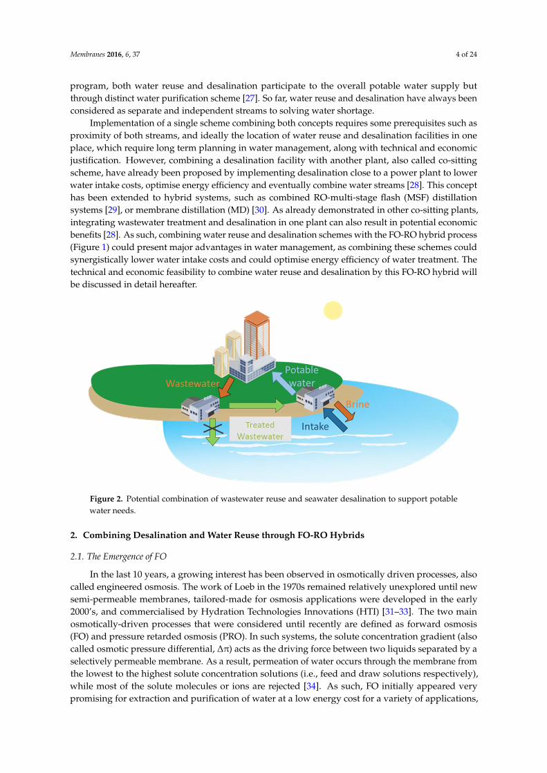
Implementation of a single scheme combining both concepts requires some prerequisites such asproximity of both streams, and ideally the location of water reuse and desalination facilities in oneplace, which require long term planning in water management, along with technical and economicjustification. However, combining a desalination facility with another plant, also called co-sittingscheme, have already been proposed by implementing desalination close to a power plant to lowerwater intake costs, optimise energy efficiency and eventually combine water streams [28]. This concepthas been extended to hybrid systems, such as combined RO-multi-stage flash (MSF) distillationsystems [29], or membrane distillation (MD) [30]. As already demonstrated in other co-sitting plants,integrating wastewater treatment and desalination in one plant can also result in potential economicbenefits [28]. As such, combining water reuse and desalination schemes with the FO-RO hybrid process(Figure 1) could present major advantages in water management, as combining these schemes couldsynergistically lower water intake costs and could optimise energy efficiency of water treatment. Thetechnical and economic feasibility to combine water reuse and desalination by this FO-RO hybrid willbe discussed in detail hereafter.
Membranes 2016, 6, 37 4 of 24
reused, but drinking water is produced from seawater desalination. In these cases, typically
wastewater treatment plant effluents and seawater intake points are in a relatively close geographic
area (as illustrated in Figure 2). In other examples, water reuse and seawater desalination are both
implemented, such as in California or several regions in Australia. In Singapore, since the
implementation of the NEWater program, both water reuse and desalination participate to the overall
potable water supply but through distinct water purification scheme [27]. So far, water reuse and
desalination have always been considered as separate and independent streams to solving water
shortage.
Implementation of a single scheme combining both concepts requires some prerequisites such
as proximity of both streams, and ideally the location of water reuse and desalination facilities in one
place, which require long term planning in water management, along with technical and economic
justification. However, combining a desalination facility with another plant, also called co-sitting
scheme, have already been proposed by implementing desalination close to a power plant to lower
water intake costs, optimise energy efficiency and eventually combine water streams [28]. This
concept has been extended to hybrid systems, such as combined RO-multi-stage flash (MSF)
distillation systems [29], or membrane distillation (MD) [30]. As already demonstrated in other co-
sitting plants, integrating wastewater treatment and desalination in one plant can also result in
potential economic benefits [28]. As such, combining water reuse and desalination schemes with the
FO-RO hybrid process (Figure 1) could present major advantages in water management, as
combining these schemes could synergistically lower water intake costs and could optimise energy
efficiency of water treatment. The technical and economic feasibility to combine water reuse and
desalination by this FO-RO hybrid will be discussed in detail hereafter.
Figure 2. Potential combination of wastewater reuse and seawater desalination to support potable
water needs.
2. Combining Desalination and Water Reuse through FO-RO Hybrids
2.1. The Emergence of FO
In the last 10 years, a growing interest has been observed in osmotically driven processes, also
called engineered osmosis. The work of Loeb in the 1970s remained relatively unexplored until new
semi-permeable membranes, tailored-made for osmosis applications were developed in the early
2000’s, and commercialised by Hydration Technologies Innovations (HTI) [31–33]. The two main
osmotically-driven processes that were considered until recently are defined as forward osmosis (FO)
and pressure retarded osmosis (PRO). In such systems, the solute concentration gradient (also called
osmotic pressure differential, ∆π) acts as the driving force between two liquids separated by a
Figure 2. Potential combination of wastewater reuse and seawater desalination to support potablewater needs.
2. Combining Desalination and Water Reuse through FO-RO Hybrids
2.1. The Emergence of FO
In the last 10 years, a growing interest has been observed in osmotically driven processes, alsocalled engineered osmosis. The work of Loeb in the 1970s remained relatively unexplored until newsemi-permeable membranes, tailored-made for osmosis applications were developed in the early2000’s, and commercialised by Hydration Technologies Innovations (HTI) [31–33]. The two mainosmotically-driven processes that were considered until recently are defined as forward osmosis(FO) and pressure retarded osmosis (PRO). In such systems, the solute concentration gradient (alsocalled osmotic pressure differential, ∆π) acts as the driving force between two liquids separated by aselectively permeable membrane. As a result, permeation of water occurs through the membrane fromthe lowest to the highest solute concentration solutions (i.e., feed and draw solutions respectively),while most of the solute molecules or ions are rejected [34]. As such, FO initially appeared verypromising for extraction and purification of water at a low energy cost for a variety of applications,

Membranes 2016, 6, 37 5 of 24
such as food concentration, wastewater concentration, water reuse and seawater desalination [34].This sparked intense research, as demonstrated by the exponential increase of publications in recentyears [35]. Several reviews have been published since 2005 discussing the interests, principles aswell as the limitations and challenges for future development of the FO process. Those reviewmore specifically discussed mass transfer limitations [34,36,37], membrane developments [36,38],fouling [39], rejection of trace organic contaminants [40], optimised draw solutions [38,41,42], energyaspects [43,44], potential applications [34,38] including wastewater treatment [35], desalination [44]and hybridisation of FO with other processes [45]. However, so far, none of this review has beendedicated to the potential application of forward osmosis in the context of combining desalination andwater reuse.
Although FO on its own can be considered as a low energy process, the applications for which itcan be used as a stand-alone process are limited. In fact, pure water extracted from the feed solutionis only transferred to a (draw) solution with a higher osmotic potential, and as such, is rarely usableas is. A second process in which water is extracted from this solution is thus required, and this isgenerally the energy intensive step. FO has been initially considered using artificial draw solutionswith very high osmotic pressure [34], but the need to regenerate the artificial draw solution negativelymay affect the financial viability of many applications (energy costs of draw reconcentration systemssuch as RO or membrane distillation [44,46,47] and costs of draw replenishment due to draw solutionleakages [42]). In addition, due to the closed-loop configuration and imperfect rejection of membranes,contaminants accumulation may occur [48]. Alternatively, new applications have been developedmore recently to avoid the draw re-concentration step by combining existing streams and hybridisingFO with other processes in once-through systems, not in closed loop [45].
2.2. The FO-RO Hybrid Process
The interest in combining wastewater and seawater streams was only recently sparked by the newdevelopments in FO. Combining water reuse and SWRO has been referred to as the FO-RO hybrid(Figure 3 and [49,50]) or osmotic dilution [51]. The FO-RO hybrid discussed in this study has to bedistinguished from other closed-loop FO concepts used for desalination, as the FO-RO hybrid is aonce-through system that does not require recovery of a highly concentrated draw solution [52–54].In the FO-RO hybrid, water is transferred from an impaired water source (a low salinity feed solution,e.g., secondary effluent) to seawater (used as draw solution) by the osmotic gradient in the FO step.
Membranes 2016, 6, 37 5 of 24
selectively permeable membrane. As a result, permeation of water occurs through the membrane
from the lowest to the highest solute concentration solutions (i.e., feed and draw solutions
respectively), while most of the solute molecules or ions are rejected [34]. As such, FO initially
appeared very promising for extraction and purification of water at a low energy cost for a variety of
applications, such as food concentration, wastewater concentration, water reuse and seawater
desalination [34]. This sparked intense research, as demonstrated by the exponential increase of
publications in recent years [35]. Several reviews have been published since 2005 discussing the
interests, principles as well as the limitations and challenges for future development of the FO
process. Those review more specifically discussed mass transfer limitations [34,36,37], membrane
developments [36,38], fouling [39], rejection of trace organic contaminants [40], optimised draw
solutions [38,41,42], energy aspects [43,44], potential applications [34,38] including wastewater
treatment [35], desalination [44] and hybridisation of FO with other processes [45]. However, so far,
none of this review has been dedicated to the potential application of forward osmosis in the context
of combining desalination and water reuse.
Although FO on its own can be considered as a low energy process, the applications for which
it can be used as a stand-alone process are limited. In fact, pure water extracted from the feed solution
is only transferred to a (draw) solution with a higher osmotic potential, and as such, is rarely usable
as is. A second process in which water is extracted from this solution is thus required, and this is
generally the energy intensive step. FO has been initially considered using artificial draw solutions
with very high osmotic pressure [34], but the need to regenerate the artificial draw solution negatively
may affect the financial viability of many applications (energy costs of draw reconcentration systems
such as RO or membrane distillation [44,46,47] and costs of draw replenishment due to draw solution
leakages [42]). In addition, due to the closed-loop configuration and imperfect rejection of membranes,
contaminants accumulation may occur [48]. Alternatively, new applications have been developed
more recently to avoid the draw re-concentration step by combining existing streams and hybridising
FO with other processes in once-through systems, not in closed loop [45].
2.2. The FO-RO Hybrid Process
The interest in combining wastewater and seawater streams was only recently sparked by the
new developments in FO. Combining water reuse and SWRO has been referred to as the FO-RO
hybrid (Figure 3 and [49,50]) or osmotic dilution [51]. The FO-RO hybrid discussed in this study has
to be distinguished from other closed-loop FO concepts used for desalination, as the FO-RO hybrid
is a once-through system that does not require recovery of a highly concentrated draw solution
[52–54]. In the FO-RO hybrid, water is transferred from an impaired water source (a low salinity feed
solution, e.g., secondary effluent) to seawater (used as draw solution) by the osmotic gradient in the
FO step.
Figure 3. Proposed integration of FO in desalination process as FO-RO hybrid (adapted from [55]). Figure 3. Proposed integration of FO in desalination process as FO-RO hybrid (adapted from [55]).
In the first study focusing on this FO-RO hybrid (and the use of secondary or tertiary treatedeffluent for seawater dilution), the authors demonstrated that the concept could lead to four majorbenefits over stand-alone seawater RO desalination [55]:

Membranes 2016, 6, 37 6 of 24
‚ lower energy use (due to lower operating pressure) for SWRO desalination thanks to theosmotic dilution,
‚ beneficial reuse of wastewater, i.e., water recycling,‚ Multi-barrier protection (two successive dense membrane processes, i.e., FO and RO) to increase
consumer confidence in water recycling,‚ Reduction in RO membrane fouling due to dilution of the pollutant load and lower
operating pressure.
2.3. Other FO-RO Hybrid Configurations
Bamaga et al. proposed to combine the FO-RO hybrid described in Figure 3 with a second FOstage implemented as an RO post-treatment [49]. In this configuration, the additional FO stage isused to dilute the RO brine with the concentrated impaired water from the first FO step to (1) furtherconcentrate the wastewater stream and so facilitate its post-treatment (for example via digestion) and(2) dilute the RO brine before disposal to limit its environmental impact. Although the additional FOpresents some potential environmental benefits, the economic and technical feasibility is questionabledue to the low permeation fluxes observed, especially in the second FO. Ultimately, recommendationsto focus on the first FO stage and optimisation of module design were given [49].
FO has been demonstrated to be a robust and simple process allowing to treat difficult streamssuch as anaerobic digester centrate or sludge [56,57], and as such could also be well adapted to treatdifficult wastewaters, mainly due to its low fouling propensity. Thus, instead of using secondarytreated wastewater (Figure 3), new concepts have emerged to consider the implementation of FOupstream in the wastewater treatment scheme, i.e., on primary treated wastewater or even the directimplementation on raw sewage. It is expected that thanks to the avoidance of some purification steps,significant cost reduction could be obtained.
One example is the concept of osmotic membrane bioreactor (OMBR) [58] where FO isimplemented within the secondary (biological) treatment. The OMBR has been developed by analogywith membrane bioreactors (MBRs), where biological degradation and clarification were operated ina single step. However, instead of using a porous ultrafiltration or microfiltration membrane as forMBR, a dense FO membrane is submerged in the bioreactor of the OMBR. As such, higher rejections ofcontaminants were observed than for MBRs, yet at lower fouling propensity [59] and thus OMBRscan produce the high water quality which is crucial in the context of potable water reuse. One majorlimitation in OMBR operation remains the salt accumulation in the OMBR tank, resulting from thehigh rejection of dissolved solids by the FO membrane and the reverse solute diffusion occurring inthe FO process [60]. This salinity build up can only be mitigated by the development of more selectivemembranes, or by decreasing the sludge retention time. Another proposed solution was the additionof ultrafiltration or microfiltration system to OMBR to create salt bleeding, but this process is morecomplex to operate since two sets of well-balanced membrane systems are needed [61,62].
As the first experiences with the OMBR operating in a secondary biological treatment are positive,with little fouling observed, it is of course interesting to envision FO treatment further upstream, forexample on the raw wastewater (or sewage) after primary treatment, as stated above (and shownin Figure 4). The interest of the water treatment community in the scheme in Figure 4 is high, asFO offers a double advantage here: not only can high quality water be recovered, in addition theconcentrated sewage stream can be more easily converted to energy via digestion (due to the higherCOD concentration) [63]. Initial experiments using FO on primary treated (screened) wastewaterdemonstrated that the accumulated fouling layer was loose and easily reversible [63], and thus foulingcan indeed be controlled. Further validations are of course required, especially with regards to cloggingissues in the feed channels, and also in terms of long term behavior—but implementing FO directlyafter primary treatment in the future could allow for significant savings in wastewater (and moreoverwater reuse) treatment costs.
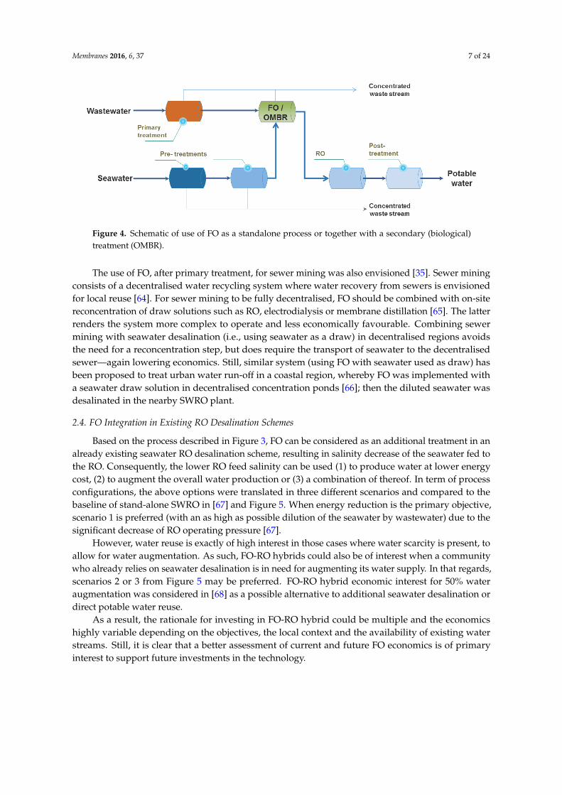
Membranes 2016, 6, 37 7 of 24Membranes 2016, 6, 37 7 of 24
Figure 4. Schematic of use of FO as a standalone process or together with a secondary (biological)
treatment (OMBR).
The use of FO, after primary treatment, for sewer mining was also envisioned [35]. Sewer mining
consists of a decentralised water recycling system where water recovery from sewers is envisioned
for local reuse [64]. For sewer mining to be fully decentralised, FO should be combined with on-site
reconcentration of draw solutions such as RO, electrodialysis or membrane distillation [65]. The latter
renders the system more complex to operate and less economically favourable. Combining sewer
mining with seawater desalination (i.e., using seawater as a draw) in decentralised regions avoids
the need for a reconcentration step, but does require the transport of seawater to the decentralised
sewer—again lowering economics. Still, similar system (using FO with seawater used as draw) has
been proposed to treat urban water run-off in a coastal region, whereby FO was implemented with a
seawater draw solution in decentralised concentration ponds [66]; then the diluted seawater was
desalinated in the nearby SWRO plant.
2.4. FO Integration in Existing RO Desalination Schemes
Based on the process described in Figure 3, FO can be considered as an additional treatment in
an already existing seawater RO desalination scheme, resulting in salinity decrease of the seawater
fed to the RO. Consequently, the lower RO feed salinity can be used (1) to produce water at lower
energy cost, (2) to augment the overall water production or (3) a combination of thereof. In term of
process configurations, the above options were translated in three different scenarios and compared
to the baseline of stand-alone SWRO in [67] and Figure 5. When energy reduction is the primary
objective, scenario 1 is preferred (with an as high as possible dilution of the seawater by wastewater)
due to the significant decrease of RO operating pressure [67].
Figure 5. Examples of block flow diagrams of baseline (existing RO) and FO-RO with recovery (R%)
for each scenario and impact on the produced water depending on FO recovery. All flow values are
in m3·h−1, initial assumption of existing RO desalination plant with water production of 1800 m3·h−1
and RO recovery of 45%
Figure 4. Schematic of use of FO as a standalone process or together with a secondary (biological)treatment (OMBR).
The use of FO, after primary treatment, for sewer mining was also envisioned [35]. Sewer miningconsists of a decentralised water recycling system where water recovery from sewers is envisionedfor local reuse [64]. For sewer mining to be fully decentralised, FO should be combined with on-sitereconcentration of draw solutions such as RO, electrodialysis or membrane distillation [65]. The latterrenders the system more complex to operate and less economically favourable. Combining sewermining with seawater desalination (i.e., using seawater as a draw) in decentralised regions avoidsthe need for a reconcentration step, but does require the transport of seawater to the decentralisedsewer—again lowering economics. Still, similar system (using FO with seawater used as draw) hasbeen proposed to treat urban water run-off in a coastal region, whereby FO was implemented witha seawater draw solution in decentralised concentration ponds [66]; then the diluted seawater wasdesalinated in the nearby SWRO plant.
2.4. FO Integration in Existing RO Desalination Schemes
Based on the process described in Figure 3, FO can be considered as an additional treatment in analready existing seawater RO desalination scheme, resulting in salinity decrease of the seawater fed tothe RO. Consequently, the lower RO feed salinity can be used (1) to produce water at lower energycost, (2) to augment the overall water production or (3) a combination of thereof. In term of processconfigurations, the above options were translated in three different scenarios and compared to thebaseline of stand-alone SWRO in [67] and Figure 5. When energy reduction is the primary objective,scenario 1 is preferred (with an as high as possible dilution of the seawater by wastewater) due to thesignificant decrease of RO operating pressure [67].
However, water reuse is exactly of high interest in those cases where water scarcity is present, toallow for water augmentation. As such, FO-RO hybrids could also be of interest when a communitywho already relies on seawater desalination is in need for augmenting its water supply. In that regards,scenarios 2 or 3 from Figure 5 may be preferred. FO-RO hybrid economic interest for 50% wateraugmentation was considered in [68] as a possible alternative to additional seawater desalination ordirect potable water reuse.
As a result, the rationale for investing in FO-RO hybrid could be multiple and the economicshighly variable depending on the objectives, the local context and the availability of existing waterstreams. Still, it is clear that a better assessment of current and future FO economics is of primaryinterest to support future investments in the technology.

Membranes 2016, 6, 37 8 of 24
Membranes 2016, 6, 37 7 of 24
Figure 4. Schematic of use of FO as a standalone process or together with a secondary (biological)
treatment (OMBR).
The use of FO, after primary treatment, for sewer mining was also envisioned [35]. Sewer mining
consists of a decentralised water recycling system where water recovery from sewers is envisioned
for local reuse [64]. For sewer mining to be fully decentralised, FO should be combined with on-site
reconcentration of draw solutions such as RO, electrodialysis or membrane distillation [65]. The latter
renders the system more complex to operate and less economically favourable. Combining sewer
mining with seawater desalination (i.e., using seawater as a draw) in decentralised regions avoids
the need for a reconcentration step, but does require the transport of seawater to the decentralised
sewer—again lowering economics. Still, similar system (using FO with seawater used as draw) has
been proposed to treat urban water run-off in a coastal region, whereby FO was implemented with a
seawater draw solution in decentralised concentration ponds [66]; then the diluted seawater was
desalinated in the nearby SWRO plant.
2.4. FO Integration in Existing RO Desalination Schemes
Based on the process described in Figure 3, FO can be considered as an additional treatment in
an already existing seawater RO desalination scheme, resulting in salinity decrease of the seawater
fed to the RO. Consequently, the lower RO feed salinity can be used (1) to produce water at lower
energy cost, (2) to augment the overall water production or (3) a combination of thereof. In term of
process configurations, the above options were translated in three different scenarios and compared
to the baseline of stand-alone SWRO in [67] and Figure 5. When energy reduction is the primary
objective, scenario 1 is preferred (with an as high as possible dilution of the seawater by wastewater)
due to the significant decrease of RO operating pressure [67].
Figure 5. Examples of block flow diagrams of baseline (existing RO) and FO-RO with recovery (R%)
for each scenario and impact on the produced water depending on FO recovery. All flow values are
in m3·h−1, initial assumption of existing RO desalination plant with water production of 1800 m3·h−1
and RO recovery of 45%
Figure 5. Examples of block flow diagrams of baseline (existing RO) and FO-RO with recovery (R%)for each scenario and impact on the produced water depending on FO recovery. All flow values are inm3¨ h´1, initial assumption of existing RO desalination plant with water production of 1800 m3¨ h´1
and RO recovery of 45%.
2.5. FO Economics: Need for Higher Permeation Flux
Initial attempts demonstrated that FO-RO hybrids in literature can have positive economicscompared to stand-alone SWRO, due to energy savings (osmotic dilution) and maintenance savingsresulting from lower fouling tendency estimated from laboratory or pilot scale testing [42,55,69].However, those initial studies did not account for some drawbacks and challenges of the hybrid thatneed to be considered as well [67] in order to have a fair assessment of FO-RO hybrids comparedto SWRO:
‚ Implementation of FO will require investment costs‚ Energy consumption in RO is getting close to the thermodynamic limit and additional energy
savings may become marginal [70].‚ The FO-RO hybrid also has to demonstrate advantages in comparison with two independent and
established water treatment streams (i.e., water reuse and/or desalination) or simple mixing ofthese streams before treatment [71].
Several attempts were made to make a clear economic assessment of FO-RO hybrid systems.Cath et al. completed a first economic evaluation of their proposed hybrid FO-RO system by comparingthe implementation of an FO unit to an expansion of SWRO capacity, to increase seawater desalinationplant capacity. Their estimations showed 0.43US $¨m´3 cost savings of the FO-RO hybrid compared tostand-alone RO. However, this estimation was based on the assumption of a high energy cost, andinvestment costs of FO only related to membrane costs [50]. Another study revealed that FO can bea viable technology thanks to significant energy decrease from 2.5 to 4 kWh¨m´3 for RO seawaterdesalination down to 1.5 kWh¨m´3 when using FO-RO hybrid [72]. However, this requires a dilutionof seawater by a factor of 2.5, the process relies then mostly on water reuse.
It is clear that the key to improving FO process economics is in the increase of FO fluxes [38,42,67].A recent and complete study established that FO-RO hybrid systems (operated in once-through, notin closed loop), will only become economically sustainable if lower membrane costs (30 US $¨m´2)and/or higher fluxes (ě15 L¨m´2¨h´1) than for existing commercial membranes can be obtained [51].Another recent study confirmed that the current state of development of commercial FO membranemodules is insufficient for sustainable FO-RO hybrid economics due to the high capital investmentcost (CAPEX—which is related to low permeation flux, low packing density, and high membranecosts) [67]. A threshold flux value of 30 L¨m´2¨h´1 was proposed as minimum average permeationflux to guarantee FO economic sustainability.

Membranes 2016, 6, 37 9 of 24
A very recent study, using levelised cost indicator, demonstrated that FO-RO hybrid could bea favourable alternative for 50% water augmentation in comparison with extension of SWRO orimplementation of DPR [68]. This study also showed that the economic viability of the FO-RO hybridwas highly dependent from the extent of wastewater treatment required and the permeation fluxin FO.
Despite a significant body of research on the development of tailor-made membranes, untilvery recently, only few commercial membranes were available. A new generation of membranesand modules is now emerging on the market, but their economics and performance still needcareful assessment (See Section 3). As an alternative to FO, the concept of pressure assisted osmosis(PAO) has arisen recently, and appears promising to overcome the current flux limitations of FO.Opportunities and challenges of novel membranes, novel modules and the use of PAO operation,to improve permeation flux in osmotic processes, are critically and systematically discussed in thefollowing sections.
3. Recent Development to Improve Flux in FO
3.1. Membrane Development
Permeation flux in FO is largely dependent on membrane characteristics. FO membranes areusually asymmetric polymeric membranes. The parameters used to characterize these membranesare typically the pure water and salt permeability of the rejection layer (factors A and B, respectively),and the structural parameter of the support layer (S). The ideal FO membrane features a high A value(high water flux), low B (low salt passage), low S (to limit internal concentration polarisation, ICP)and sufficient mechanical strength to support industrial operation at moderate pressure [34]. Since theintroduction in the 1990s of the first FO commercial membrane by HTI, a tremendous amount of workhas been performed to optimise FO membrane [38]. Two main strategies have been followed in thisrespect: (1) developing dedicated membranes for FO or (2) adapting existing NF/RO membranes.
The first strategy was by far the most studied and recent reviews reported on numerousmembrane developments that have been published since 2005 on both hollow fibre and flat sheetconfigurations [36,38,43]. Among them, new approaches have been used to develop thin-filmcomposite (TFC) membranes which consist of a selective polyamide layer formed by interfacialpolymerisation on top of a polysulfone porous substrate [73], similar to NF/RO membranes. TheTFC membranes offer more flexibility than cellulose triacetate (CTA) membranes in choosing activeand support layer, and as such TFC membranes with higher permeability and reduced ICP weresynthesized, allowing for higher water fluxes [74]. The concept of TFC membranes has been extendedto the synthesis of double-skinned layer FO membranes [73], leading to lower ICP and fouling.Another approach for TFC membrane improvement was the development of hydrophilic supportlayers leading to lower ICP and subsequent higher water flux, but with the drawback lower saltrejection [73]. The use of nanofibres as membrane support layer to limit ICP is also a new way toimprove TFC membranes [75]. Recent work also mentioned the layer-by-layer approach (LbL) thatallows formulating tailor-made membranes [76–79]. In addition, several publications referred to nextgenerations of biomimetic FO membranes using Aquaporin Z [80,81], carbon nanotubes (CNT) [82,83]or graphene [84].
The second strategy to novel FO membranes consists in adapting existing RO membranes. Suchmembranes exhibit high permeabilities and high salt rejection, but have the drawback of a thick, poroushydrophobic support layer [85] which is inadequate for FO due to the severe ICP occurring [86,87].Thus, membrane support layers were modified by removing the backing support layer [87], or byimproving wettability using polydopamine coating [88]. Water flux was increased by up to 10 times incomparison with the parent RO membranes at high osmotic driving forces. The use of conventional NFmembranes in FO applications was also proposed in 2007 [89]. Then, a number of studies [78,79,89–93]considered the development of FO membranes with more porous active layers, similar to those found

Membranes 2016, 6, 37 10 of 24
in NF membranes, to increase water permeability. However, the water flux obtained from the modifiedNF-FO membrane was not deemed high enough, also mainly due to ICP. Additionally, the reversiblesalt diffusion (RSD) values reported for NF-like FO membranes are generally high or require the use ofdivalent salts as draw solutions [78,79,92,93].
Overall, findings from academic research have been translated into the development and (pre-)commercialisation of several FO membranes—described hereafter in Table 1. It has to be noticedthat HTI, which has been the main leader in FO membrane development and main provider toacademic research, is no longer capable to supply membranes [94]. Other membrane suppliersnowadays offer membrane samples but information in the literature remains limited due to their morerecent development.
Based on information available (Table 1), it can be noticed that most of the development hasfocussed on TFC flat sheet membranes; Hollow fiber (HF) membranes are still in the developmentphase, and have not been commercialised to a high extent yet. Novel flat sheet membranes whichhave incorporated the TFC approach, and several new biomimetic membranes (CNT and aquaporin)are now commercially available [95]. As a result, several companies (Porifera, Woongjin Chemicals,CSM-Toray, Oasys Water) claim water permeation fluxes of around 30 L¨m´2¨h´1 when using 1 M(NaCl, KCl) draw solutions, with reverse salt diffusion being below 1 g¨L´1. Such performancesrepresent a significant improvement in comparison with the HTI CTA membrane, which still acts as areference. It is clear that these novel membranes will surely help to further develop FO applications.
Table 1. Development and performance of commercial FO membranes (performance as seen in theliterature with deionised water (DI) as feed and active layer facing feed solution (AL-FS) used asmembrane orientation (data compiled in July 2015)).
Company Type CommercialName Status
FO Performance
Ref.Draw
Jw Js/JwL¨ m´2¨ h´1 g¨ L´1
HTI flat-sheet CTA-NW commercial 2M NaCl 8.5 0.1 [96]HTI flat-sheet CTA-ES commercial 1M NaCl 10.1 0.5 [97]HTI flat-sheet TFC commercial 1M NaCl 10 0.8 [97]
Oasys flat-sheet TFC pre-commercial 1M NaCl 30 0.7 [97]Woongjin Chemicals flat-sheet TFC-1 development 1M KCl 16 1.3 [98]Woongjin Chemicals flat-sheet TFC-2 development 1M KCl 27.9 0.4 [99]
Aquaporin flat-sheet AqP pre-commercial 1M NaCl 9.5 [100]CSM-Toray flat-sheet FO membrane commercial 1M NaCl 35.0 <0.5 [101]
Porifera flat-sheet PFO elements commercial 1M NaCl 33.0 0.2–0.6 [102]Samsung hollow fiber HFFO lumens development 1M KCl 9.3 0.6 [103]Toyobo hollow fiber – commercial – – – [95]
3.2. Module Development
Among the challenges to overcome in FO, module design is certainly of a high importance.An ideal FO module is expected to demonstrate an appropriate trade-off between (1) a maximisedsurface area (i.e., high packing density) and (2) a minimised pressure drop, while (3) allowing forlimited ECP and particle deposition [35,63]. In the early stage of FO and PRO research, FO moduleswere mainly adapted from RO configurations, but these spiral-wound modules proved to have limitedefficiency as a result of imperfect hydraulics on the permeate (draw solution) side [34,104,105]. Indeed,FO modules differ from classical RO ones as fluids (feed and draw solutions) have to circulate on bothsides of the membrane. As such, FO modules require four ports (feed and draw inlets and outlets)and optimised hydraulics on the feed and the draw side. Some examples of flat sheet FO modulearrangement are described in Figure 6.
Membranes 2016, 6, 37 11 of 24
Membranes 2016, 6, 37 10 of 24
Based on information available (Table 1), it can be noticed that most of the development has
focussed on TFC flat sheet membranes; Hollow fiber (HF) membranes are still in the development
phase, and have not been commercialised to a high extent yet. Novel flat sheet membranes which
have incorporated the TFC approach, and several new biomimetic membranes (CNT and aquaporin)
are now commercially available [95]. As a result, several companies (Porifera, Woongjin Chemicals,
CSM-Toray, Oasys Water) claim water permeation fluxes of around 30 L·m−2·h−1 when using 1 M
(NaCl, KCl) draw solutions, with reverse salt diffusion being below 1 g·L−1. Such performances
represent a significant improvement in comparison with the HTI CTA membrane, which still acts as
a reference. It is clear that these novel membranes will surely help to further develop FO applications.
Table 1. Development and performance of commercial FO membranes (performance as seen in the
literature with deionised water (DI) as feed and active layer facing feed solution (AL-FS) used as
membrane orientation (data compiled in July 2015)).
Company Type Commercial
Name Status
FO Performance
Ref. Draw
Jw Js/Jw
L·m−2·h−1 g·L−1
HTI flat-sheet CTA-NW commercial 2M NaCl 8.5 0.1 [96]
HTI flat-sheet CTA-ES commercial 1M NaCl 10.1 0.5 [97]
HTI flat-sheet TFC commercial 1M NaCl 10 0.8 [97]
Oasys flat-sheet TFC pre-commercial 1M NaCl 30 0.7 [97]
Woongjin Chemicals flat-sheet TFC-1 development 1M KCl 16 1.3 [98]
Woongjin Chemicals flat-sheet TFC-2 development 1M KCl 27.9 0.4 [99]
Aquaporin flat-sheet AqP pre-commercial 1M NaCl 9.5 [100]
CSM-Toray flat-sheet FO membrane commercial 1M NaCl 35.0 <0.5 [101]
Porifera flat-sheet PFO elements commercial 1M NaCl 33.0 0.2–0.6 [102]
Samsung hollow fiber HFFO lumens development 1M KCl 9.3 0.6 [103]
Toyobo hollow fiber – commercial – – – [95]
3.2. Module Development
Among the challenges to overcome in FO, module design is certainly of a high importance. An
ideal FO module is expected to demonstrate an appropriate trade-off between (1) a maximised
surface area (i.e., high packing density) and (2) a minimised pressure drop, while (3) allowing for
limited ECP and particle deposition [35,63]. In the early stage of FO and PRO research, FO modules
were mainly adapted from RO configurations, but these spiral-wound modules proved to have
limited efficiency as a result of imperfect hydraulics on the permeate (draw solution) side
[34,104,105]. Indeed, FO modules differ from classical RO ones as fluids (feed and draw solutions)
have to circulate on both sides of the membrane. As such, FO modules require four ports (feed and
draw inlets and outlets) and optimised hydraulics on the feed and the draw side. Some examples of
flat sheet FO module arrangement are described in Figure 6.
Figure 6. Illustrations of flat-sheet FO membranes arranged in (a) spiral wound and (b) plate and
frame modules design.
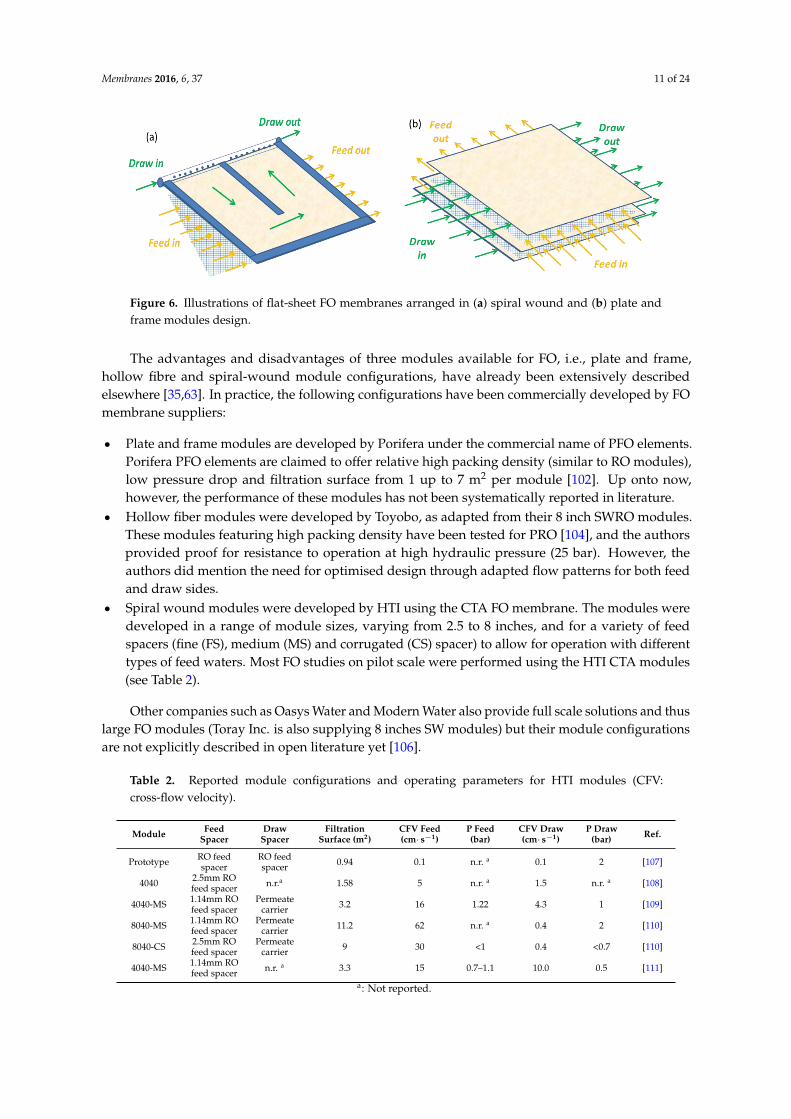
The advantages and disadvantages of three modules available for FO, i.e., plate and frame,
hollow fibre and spiral-wound module configurations, have already been extensively described
Figure 6. Illustrations of flat-sheet FO membranes arranged in (a) spiral wound and (b) plate andframe modules design.
The advantages and disadvantages of three modules available for FO, i.e., plate and frame,hollow fibre and spiral-wound module configurations, have already been extensively describedelsewhere [35,63]. In practice, the following configurations have been commercially developed by FOmembrane suppliers:
‚ Plate and frame modules are developed by Porifera under the commercial name of PFO elements.Porifera PFO elements are claimed to offer relative high packing density (similar to RO modules),low pressure drop and filtration surface from 1 up to 7 m2 per module [102]. Up onto now,however, the performance of these modules has not been systematically reported in literature.
‚ Hollow fiber modules were developed by Toyobo, as adapted from their 8 inch SWRO modules.These modules featuring high packing density have been tested for PRO [104], and the authorsprovided proof for resistance to operation at high hydraulic pressure (25 bar). However, theauthors did mention the need for optimised design through adapted flow patterns for both feedand draw sides.
‚ Spiral wound modules were developed by HTI using the CTA FO membrane. The modules weredeveloped in a range of module sizes, varying from 2.5 to 8 inches, and for a variety of feedspacers (fine (FS), medium (MS) and corrugated (CS) spacer) to allow for operation with differenttypes of feed waters. Most FO studies on pilot scale were performed using the HTI CTA modules(see Table 2).
Other companies such as Oasys Water and Modern Water also provide full scale solutions and thuslarge FO modules (Toray Inc. is also supplying 8 inches SW modules) but their module configurationsare not explicitly described in open literature yet [106].
Table 2. Reported module configurations and operating parameters for HTI modules (CFV:cross-flow velocity).
Module FeedSpacer
DrawSpacer
FiltrationSurface (m2)
CFV Feed(cm¨ s´1)
P Feed(bar)
CFV Draw(cm¨ s´1)
P Draw(bar) Ref.
Prototype RO feedspacer
RO feedspacer 0.94 0.1 n.r. a 0.1 2 [107]
4040 2.5mm ROfeed spacer n.r.a 1.58 5 n.r. a 1.5 n.r. a [108]
4040-MS 1.14mm ROfeed spacer
Permeatecarrier 3.2 16 1.22 4.3 1 [109]
8040-MS 1.14mm ROfeed spacer
Permeatecarrier 11.2 62 n.r. a 0.4 2 [110]
8040-CS 2.5mm ROfeed spacer
Permeatecarrier 9 30 <1 0.4 <0.7 [110]
4040-MS 1.14mm ROfeed spacer n.r. a 3.3 15 0.7–1.1 10.0 0.5 [111]
a: Not reported.

Membranes 2016, 6, 37 12 of 24
One of the main gaps in knowledge of FO modules is the impact of hydraulic pressure onthe performance. The main reason why this has not been systematically investigated is that FO isconsidered as an osmotic driven process. However, one cannot ignore pressure drop along modulesinherent to any membrane processes practical implementation. In fact, mass transfers are usuallyoptimised by the implementation of spacers that create turbulences and consequently limit particledeposition and concentration polarisation, but at the cost of additional pressure drop [112,113]. Onlyone study from Kim et al. in 2011 ([109], Table 2) mentioned the impact of feed and draw CFV onpressure drop and pressure build up in spiral wound FO modules. A minimum amount of hydraulicpressure (0.12 and 0.28 bar on feed and draw sides respectively) needed to be applied to allow waterto flow through the module even at the lowest flowrates. It was clearly demonstrated that CFV andchannel pressure drop were closely connected in both channels (feed and draw), and were highlydependent on the spacer type used. Additionally, it was observed that applying pressure on thefeed side lead to a narrowing of the draw channel and consequently, to a pressurisation of the drawside. Similar observations were also described in PRO configuration where pressurisation of the drawchannel led to narrowing of the feed channel when diamond shape spacer was used to support themembrane [114]. In fact, as for other membrane processes, spacer design is of crucial importance.Among the modules proposed by HTI in former studies, even if not always specified, at least twotypes of draw spacers have been tested, i.e., permeate carrier [109,110] and RO feed spacer [107]. It isalso generally observed that modules are operated at very low CFV on the draw side (Table 2), maybethanks to the low fouling behaviour draw solution but also possibly limited by the important pressuredrop occurring when permeate carrier are used [110].
Not many studies have tried to use computational fluid dynamics (CFD) for FO module designyet. In addition, among the few studies reporting CFD approaches in FO, none of them considered theimpact of pressure in the different spacer-filled channels. Most of the approaches were dedicated tothe demonstration of models capable of simulating FO systems [115,116] or to demonstrate currentmass transfer limitations, the need for improvement of membrane separation properties and the studyof spacer designs to limit ECP [117,118].
More work is thus required to better understand how CFV, spacer type and module configurationare connected to pressure drop and hydraulic pressure in the spacer-filled channels, to determine theoptimum configuration for FO up-scaling. CFD modelling could help in further understanding masstransfer limitations in FO modules and to propose optimised designs.
3.3. The Concept of Pressure Assisted Osmosis (PAO)
The concept of pressure assisted osmosis (PAO) [119], relies on the application of moderatepressure on the feed side of a FO system to enhance water permeation through the membrane (Figure 7).As such, by a synergistic effect of hydraulic and osmotic pressure, PAO can improve FO fluxes andthus FO process economics due to lower membrane surface requirements.
The impact of hydraulic pressure on the feed of FO systems was only studied recently.The first study mentioning hydraulic pressure on the feed side was presented as a conference paperin 2011 and already discussed the interest of pulsations and moderate hydraulic pressure to improvepermeation flux [120]. The same year, another study also showed that hydraulic pressure, even if verymoderate, is needed in FO systems to allow water cross-flow within the feed and draw channels of anFO module [109]. The effect of transmembrane pressure in FO was further evaluated, assuming that FOindustrial applications require pressurisation for water circulation within spiral wound modules [97].However, given the low applied pressure (up to 3.4 bar) in comparison with the osmotic pressuredriving force (45 bar),no clear impact on flux was observed for the three membranes tested.
The implementation of hydraulic pressure in FO as a concept only appeared in 2012 and wasinitially named ‘’pressure assisted forward osmosis” [121], also later on called ‘’assisted forwardosmosis” [122] and ‘’pressure assisted osmosis” (PAO) [123,124]. Initial research using HTI CTAmembranes confirmed flux improvement as a result of PAO operation when compared to FO [121,122].

Membranes 2016, 6, 37 13 of 24
On the one hand, it was observed by some that the water flux increment remained lower thanexpected by the additional driving force, attesting for enhanced ICP partly mitigating the beneficialuse of hydraulic pressure, and thus indicating that PAO might not be beneficial [125]. On the otherhand, evidence of membrane deformation occurring due to pressurisation of the membrane overdraw channel spacers was also observed. The membrane stretching over spacers strands led toincreased membrane permeability and consequently significant improvement of the water flux wasobserved [122]. Comparative investigations of PAO in continuous and discontinuous mode alsoconfirmed that water flux increases with hydraulic pressure [123]. Interestingly, and as a result of moreintense ICP in PAO operation, RSD decreased, tackling a second limitation of current FO operation,and thus rekindling the interest in PAO [124].
Membranes 2016, 6, 37 12 of 24
channel pressure drop were closely connected in both channels (feed and draw), and were highly
dependent on the spacer type used. Additionally, it was observed that applying pressure on the feed
side lead to a narrowing of the draw channel and consequently, to a pressurisation of the draw side.
Similar observations were also described in PRO configuration where pressurisation of the draw
channel led to narrowing of the feed channel when diamond shape spacer was used to support the
membrane [114]. In fact, as for other membrane processes, spacer design is of crucial importance.
Among the modules proposed by HTI in former studies, even if not always specified, at least two
types of draw spacers have been tested, i.e., permeate carrier [109,110] and RO feed spacer [107]. It is
also generally observed that modules are operated at very low CFV on the draw side (Table 2), maybe
thanks to the low fouling behaviour draw solution but also possibly limited by the important
pressure drop occurring when permeate carrier are used [110].
Not many studies have tried to use computational fluid dynamics (CFD) for FO module design
yet. In addition, among the few studies reporting CFD approaches in FO, none of them considered
the impact of pressure in the different spacer-filled channels. Most of the approaches were dedicated
to the demonstration of models capable of simulating FO systems [115,116] or to demonstrate current
mass transfer limitations, the need for improvement of membrane separation properties and the
study of spacer designs to limit ECP [117,118].
More work is thus required to better understand how CFV, spacer type and module
configuration are connected to pressure drop and hydraulic pressure in the spacer-filled channels, to
determine the optimum configuration for FO up-scaling. CFD modelling could help in further
understanding mass transfer limitations in FO modules and to propose optimised designs.
3.3. The Concept of Pressure Assisted Osmosis (PAO)
The concept of pressure assisted osmosis (PAO) [119], relies on the application of moderate
pressure on the feed side of a FO system to enhance water permeation through the membrane (Figure
7). As such, by a synergistic effect of hydraulic and osmotic pressure, PAO can improve FO fluxes
and thus FO process economics due to lower membrane surface requirements.
Figure 7. Illustration of water fluxes obtained (Jw) in osmotic processes as a function of hydraulic
pressure applied (P) on the low salinity solution, and the potential of PAO to provide high fluxes.
The impact of hydraulic pressure on the feed of FO systems was only studied recently. The first
study mentioning hydraulic pressure on the feed side was presented as a conference paper in 2011
and already discussed the interest of pulsations and moderate hydraulic pressure to improve
Figure 7. Illustration of water fluxes obtained (Jw) in osmotic processes as a function of hydraulicpressure applied (P) on the low salinity solution, and the potential of PAO to provide high fluxes.
More recent work compared the performance of CTA membranes in PAO mode to that ofcommercial TFC membranes. In addition to allow for higher flux in FO process, the TFC membraneswere also more responsive to hydraulic pressure applied in the PAO process, and thus showed clearflux enhancement (up to 25 L¨m´2¨h´1) at moderate hydraulic pressure [126]. In addition to providingextra driving force for permeation flux, hydraulic pressure was also observed to limit RSD and increasethe water permeability due to membrane deformation when TFC membranes were used. Therefore,PAO constitutes a promising alternative to tackle the permeability-selectivity trade-off of FO.
4. Challenges Associated with FO Flux Improvement
4.1. Fouling and Cleaning
The behaviour of individual or combined model foulants (humic acids, alginate, proteins,silicates, calcium) under different operating FO conditions has been extensively described in theliterature [60,69,127–138] and summarised in a recent extended review [39]. In these studies,it is generally observed that fouling in FO remains moderate and easily reversible. The onlyrecommendation, to avoid irreversible fouling in the support layer when wastewater is used asfeed [139] was to operate the FO membranes with the membrane active layer facing the feed solution(AL-FS) [135,140]. Up to now, most FO fouling studies were performed in FO operation without applied

Membranes 2016, 6, 37 14 of 24
hydraulic pressure on the feed or draw, and mostly using the benchmark CTA HTI FO membrane,which demonstrates a relatively low permeation flux [60,69,128–135]. It is clear that increased fluxes(either due to PAO operation or by using high permeability membranes) will impact the foulingbehaviour. In addition, in PAO operation there is an applied pressure (in contrast to FO), and a clearresearch question remains on the respective impact of flux and pressure on the fouling behaviour.
The impact of operating flux on fouling behaviour has been well studied for pressure drivenmembrane processes [141]. The concept of critical flux [142] has been widely used when describing theimpact of flux on fouling for membrane bioreactors [143,144], and also for other hydraulic pressuredriven membrane processes such as RO [145,146]. It has been demonstrated that high water permeation(above the critical flux) led to enhanced fouling; thus, operating below the defined critical fluxis preferred for sustainable long-term filtration. The evidence of critical flux was first revealedfor FO in first studies using HTI CTA membranes, with the support layer facing the foulant-feedsolution and under elevated osmotic driving force [140,147]. Further evidence of critical flux wasdemonstrated in FO studies, when using the conditions that can be expected in the FO-RO hybridsystem, namely operation in AL-FS mode at moderate osmotic pressure differences [135,148]. Thosestudies demonstrated that the low fouling behaviour often mentioned for FO is mainly due to theoperation at low permeation fluxes. At higher initial fluxes, the fouling cake was more compacted onthe membrane surface and consequently significant flux decline was observed over time.
Only recently, more studies have been published that consider the impact of moderate hydraulicpressure on fouling behaviour. Typically, higher fouling propensity and lower reversibility of combinedorganic–colloidal fouling (alginate and silica) was reported when hydraulic pressure was appliedat relatively high hydraulic pressures (7–19 bar) [149]. Two recent studies [150,151] confirmed thehypothesis raised that PAO fouling was a consequence of both hydraulic and osmotic driving forces(i.e., combination of fouling cake compaction and RSD by analogy with RO and FO fouling mechanismsrespectively [152]). Typically, in PAO operation, even at similar flux compared to FO operation, athinner but more compact fouling layer than in FO is observed, leading to more flux decrease [150].The flux decrease is higher than in FO, but still more reversible than in RO [151].
Tackling fouling is a key aspect in membrane processes and is usually achieved via a combinationof fouling mitigation (i.e., membrane and module development and/or optimisation of hydrodynamicconditions) and adapted cleaning strategies [153]. FO studies dedicated to fouling mitigation viamembrane surface modification and cleaning are discussed successively here.
TFC membranes developed for FO have proven to initially enhance water permeation, althoughtheir much rougher surface generally results in more fouling [154,155] as already demonstrated forNF/RO TFC membranes [156,157]. Some membrane developments have recently been dedicatedto fouling mitigation such as double skinned membranes [77,158], membrane surface modificationapproaches using amine enriched, polyethylene-glycol enriched [77,158,159] and silver-titaniumnanoparticles [160]. Some promising results have been observed, but studies remain scarce and limitedto lab-scale and home-made membranes. However, it has been observed elsewhere that membranesurface properties had ultimately a low impact on fouling behaviour since it was limited to the earlystage of the foulant deposition [148].
Since in FO operation at low fluxes, relatively little fouling has been observed so far, cleaningstrategies in FO have mostly been limited to applying simple physical methods to improve turbulence(i.e., high CFV, use of spacers or pulsed flow [128]). Chemical cleaning and air scouring also providedpositive results, but were mostly not necessary as physical cleaning proved to be sufficient [72,161].Similarly to hydraulic backwashing used for porous membranes, osmotic backwashing has beentested for osmotic processes. For FO, the exact impact of osmotic backwashing on foulingcontrol is unclear: some studies mention a significant recovery of initial flux after cleaning of thefouled membrane [56,162,163], while other work only observed a very low impact on the foulingremoval [161,164]. Following on a former study on RO [165], a recent publication therefore proposedan optimised sequence for FO/PAO cleaning, which consists of osmotic backwashing to detach the

Membranes 2016, 6, 37 15 of 24
foulant cake from the membrane surface and high CFV operation to flush the feed channel with freshwater to remove the foulants that were dislodged from the surface. This method proved to be efficient,even at high FO permeation flux and in PAO operation [148,150]. A more detailed insight in foulingand cleaning mechanisms is starting to emerge (Figure 8), which shows that even high flux membranesoperated in PAO mode can be cleaned without the need for chemicals.Membranes 2016, 6, 37 15 of 24
Figure 8. High flux FO and PAO fouling and cleaning (osmotic backwash and high cross-flow velocity
flushing (adapted from [150]).
4.2. Rejection of Trace Organic Contaminants
To ensure water safety in FO-RO hybrids, TrOCs is of course of concern. TrOCs include
endocrine-disrupting chemicals, pharmaceutically active compounds, pesticides, and disinfection
by-products. They are present in impaired water in ng/L to µg/L levels [166,167], and could represent
a human and environmental threat, even at low concentrations [48]. Recently, extended research was
performed to evaluate FO as a barrier against TrOC, especially in association with RO [108]. A recent
review summarised recent studies dedicated to the fate of TrOC in the FO process [40]. Among the
studies cited, it was observed that the FO process may provide a robust barrier for most TrOCs, but
for some TrOCs, only limited rejection was found. In addition, most of the FO studies on TrOC were
carried out using the commercial HTI CTA membrane, which demonstrates relative low permeation
fluxes (which could impact the low TrOC rejection).
Of the novel membranes, biomimetic membranes incorporating Aquaporins have demonstrated
higher rejections of small neutral organic pollutants at similar permeation flux compared to the HTI
CTA [100]. The commercial TFC membrane developed by Oasys Water has also been recently
evaluated with regards to TrOC rejection [168] and demonstrated higher rejections of neutral TrOC
compared to the HTI CTA, which was attributed to a higher active layer structural factor and a more
negative charge. Another recent study compared several membranes and confirmed higher rejections
of TFC membranes compared to the HTI membrane (Figure 9), especially for the smaller neutral
TrOCs (>80% rejection for all TrOCs studied for HTI TFC, >90% for Porifera, >98% for Aquaporin).
The increased rejections compared to the HTI CTA were mainly due to increased steric hindrance
(and thus a smaller active layer pore size). However, it was clearly shown that rejection of TrOCs
dropped sharply when the membranes were operated in PAO, most likely as a result of a combination
of membrane deformation under pressure, more ECP and less RSD. As such, in PAO-RO hybrids,
attention has to be paid to FO membrane mechanical resistance when it comes to TrOC rejection
(while deformation is interesting in terms of flux in PAO).
Figure 8. High flux FO and PAO fouling and cleaning (osmotic backwash and high cross-flow velocityflushing (adapted from [150]).
4.2. Rejection of Trace Organic Contaminants
To ensure water safety in FO-RO hybrids, TrOCs is of course of concern. TrOCs includeendocrine-disrupting chemicals, pharmaceutically active compounds, pesticides, and disinfectionby-products. They are present in impaired water in ng/L to µg/L levels [166,167], and could representa human and environmental threat, even at low concentrations [48]. Recently, extended research wasperformed to evaluate FO as a barrier against TrOC, especially in association with RO [108]. A recentreview summarised recent studies dedicated to the fate of TrOC in the FO process [40]. Among thestudies cited, it was observed that the FO process may provide a robust barrier for most TrOCs, butfor some TrOCs, only limited rejection was found. In addition, most of the FO studies on TrOC werecarried out using the commercial HTI CTA membrane, which demonstrates relative low permeationfluxes (which could impact the low TrOC rejection).
Of the novel membranes, biomimetic membranes incorporating Aquaporins have demonstratedhigher rejections of small neutral organic pollutants at similar permeation flux compared to theHTI CTA [100]. The commercial TFC membrane developed by Oasys Water has also been recentlyevaluated with regards to TrOC rejection [168] and demonstrated higher rejections of neutral TrOCcompared to the HTI CTA, which was attributed to a higher active layer structural factor and a morenegative charge. Another recent study compared several membranes and confirmed higher rejectionsof TFC membranes compared to the HTI membrane (Figure 9), especially for the smaller neutralTrOCs (>80% rejection for all TrOCs studied for HTI TFC, >90% for Porifera, >98% for Aquaporin).

Membranes 2016, 6, 37 16 of 24
The increased rejections compared to the HTI CTA were mainly due to increased steric hindrance(and thus a smaller active layer pore size). However, it was clearly shown that rejection of TrOCsdropped sharply when the membranes were operated in PAO, most likely as a result of a combinationof membrane deformation under pressure, more ECP and less RSD. As such, in PAO-RO hybrids,attention has to be paid to FO membrane mechanical resistance when it comes to TrOC rejection (whiledeformation is interesting in terms of flux in PAO).
Membranes 2016, 6, 37 16 of 24
Figure 9. Rejection of TrOC in FO operation with four commercially available membranes (adapted
from [126].
5. Concluding Remarks
FO-RO hybrid processes offer a promising solution not only to lower desalination energy needs,
but also to increase water reuse efficiency by combining seawater desalination and water reuse.
Interestingly, due to the lower fouling propensity compared to pressure driven membrane system,
FO has the potential to treat feed water of various qualities (potentially even including raw sewage),
allowing to lower wastewater treatment costs. FO-RO schemes do require further validation but also
radical shift in current consideration of water supply. Societal (public perception of water reuse) and
water management (proximity of wastewater and desalination plants) challenges clearly need to be
overcome.
This review clearly emphasized the need for flux increase to allow for more favourable FO
economics and discussed the required technical development (i.e., novel membranes, PAO mode).
However, flux improvement is of course also associated with drawbacks, such as increased fouling,
lower rejection of TrOCs in PAO operation, and the limits of membrane mechanical resistance.
At this stage, it is, therefore, questionable if the FO/PAO-RO hybrid process will allow
sustainable and long-term operation at high flux. Additional studies are required to support
successful implementation of FO-RO hybrids in the industry:
• Up-scaling: most of the studies in literature have been conducted using small flat-sheet coupons.
More pilot scale and full scale tests are needed to assess up-scaling challenges in term of mass
transfer limitations on module scale, the effects of spacer design on pressure drop, effects of
fouling and the feasibility of cleaning strategies.
• Improved economic assessment: The economic models used for FO should be updated by
incorporation of fouling models that are better able to simulate practical implementation of
FO/PAO-RO hybrids. In addition, a better integration of cost savings from the water recycling
scheme may be considered as any treatment step avoided in the water recycling scheme as a
result of combination with desalination will help to support FO/PAO-RO hybrids economic
credentials.
Acknowledgments: The authors acknowledge the financial support of the National Centre of Excellence in
Desalination Australia which is funded by the Australian Government through the Water for the Future
Figure 9. Rejection of TrOC in FO operation with four commercially available membranes (adaptedfrom [126].
5. Concluding Remarks
FO-RO hybrid processes offer a promising solution not only to lower desalination energy needs,but also to increase water reuse efficiency by combining seawater desalination and water reuse.Interestingly, due to the lower fouling propensity compared to pressure driven membrane system,FO has the potential to treat feed water of various qualities (potentially even including raw sewage),allowing to lower wastewater treatment costs. FO-RO schemes do require further validation butalso radical shift in current consideration of water supply. Societal (public perception of water reuse)and water management (proximity of wastewater and desalination plants) challenges clearly need tobe overcome.
This review clearly emphasized the need for flux increase to allow for more favourable FOeconomics and discussed the required technical development (i.e., novel membranes, PAO mode).However, flux improvement is of course also associated with drawbacks, such as increased fouling,lower rejection of TrOCs in PAO operation, and the limits of membrane mechanical resistance.
At this stage, it is, therefore, questionable if the FO/PAO-RO hybrid process will allowsustainable and long-term operation at high flux. Additional studies are required to support successfulimplementation of FO-RO hybrids in the industry:
‚ Up-scaling: most of the studies in literature have been conducted using small flat-sheet coupons.More pilot scale and full scale tests are needed to assess up-scaling challenges in term of masstransfer limitations on module scale, the effects of spacer design on pressure drop, effects offouling and the feasibility of cleaning strategies.

Membranes 2016, 6, 37 17 of 24
‚ Improved economic assessment: The economic models used for FO should be updated byincorporation of fouling models that are better able to simulate practical implementation ofFO/PAO-RO hybrids. In addition, a better integration of cost savings from the water recyclingscheme may be considered as any treatment step avoided in the water recycling scheme as a resultof combination with desalination will help to support FO/PAO-RO hybrids economic credentials.
Acknowledgments: The authors acknowledge the financial support of the National Centre of Excellence inDesalination Australia which is funded by the Australian Government through the Water for the Future Initiative.The research leading to these results has received funding from the People Programme (Marie Curie Actions) of theSeventh Framework Programme of the European Union (FP7/2007-2013) under REA grant agreement No. 600388(TECNIOspring programme), and from the Agency for Business Competitiveness of the Government of Catalonia,ACCIO. LEQUIA and ICRA were recognized as consolidated research groups by the Catalan Government withcodes 2014-SGR-1168 and 2014-SGR-291, respectively.
Conflicts of Interest: The authors declare no conflict of interest.
References
1. UNICEF-WHO. Progress on Sanitation and Drinking Water: 2015 Update and MDG Assessment; World HealthOrganization: Geneva, Switzerland, 2015.
2. Hochstrat, R.; Wintgens, T.; Kazner, C.; Melin, T.; Gebel, J. Options for water scarcity and droughtmanagement—The role of desalination. Desalination Water Treat. 2010, 18, 96–102. [CrossRef]
3. Global_Water_Intelligence. Available online: http://www.desaldata.com (accessed on 6 October 2015).4. Elimelech, M.; Phillip, W.A. The future of seawater desalination: Energy, technology, and the environment.
Science 2011, 333, 712–717. [CrossRef] [PubMed]5. Hurlimann, A.; Dolnicar, S. Acceptance of water alternatives in australia—2009. Water Sci. Technol. 2010, 61,
2137–2142. [CrossRef] [PubMed]6. Dolnicar, S.; Hurlimann, A.; Grün, B. What affects public acceptance of recycled and desalinated water?
Water Res. 2011, 45, 933–943. [CrossRef] [PubMed]7. Fielding, K.S.; Roiko, A.H. Providing information promotes greater public support for potable recycled
water. Water Res. 2014, 61, 86–96. [CrossRef] [PubMed]8. Miller, G.W. Integrated concepts in water reuse: Managing global water needs. Desalination 2006, 187, 65–75.
[CrossRef]9. Semiat, R.; Hasson, D. Water desalination. Rev. Chem. Eng. 2012, 28, 43–60. [CrossRef]10. Shannon, M.A.; Bohn, P.W.; Elimelech, M.; Georgiadis, J.G.; Marinas, B.J.; Mayes, A.M. Science and
technology for water purification in the coming decades. Nature 2008, 452, 301–310. [CrossRef] [PubMed]11. Zhu, A.; Christofides, P.D.; Cohen, Y. On RO membrane and energy costs and associated incentives for future
enhancements of membrane permeability. J. Membr. Sci. 2009, 344, 1–5. [CrossRef]12. Zhu, A.; Christofides, P.D.; Cohen, Y. Effect of thermodynamic restriction on energy cost optimization of RO
membrane water desalination. Ind. Eng. Chem. Res. 2008, 48, 6010–6021. [CrossRef]13. Bartman, A.R.; Zhu, A.; Christofides, P.D.; Cohen, Y. Minimizing energy consumption in reverse osmosis
membrane desalination using optimization-based control. J. Process Control 2010, 20, 1261–1269. [CrossRef]14. Angelakis, A.N.; Durham, B. Water recycling and reuse in EUREAU countries: Trends and challenges.
Desalination 2008, 218, 3–12. [CrossRef]15. Tchobanoglous, G.; Leverenz, H.; Nellor, M.H.; Crook, J. Direct Potable Reuse: A Path Forward; WateReuse
Research Foundation: Alexandria, VA, USA, 2011.16. Cirja, M.; Ivashechkin, P.; Schäffer, A.; Corvini, P.X. Factors affecting the removal of organic micropollutants
from wastewater in conventional treatment plants (CTP) and membrane bioreactors (MBR). Rev. Environ.Sci. Biotechnol. 2008, 7, 61–78. [CrossRef]
17. Jelic, A.; Gros, M.; Ginebreda, A.; Cespedes-Sánchez, R.; Ventura, F.; Petrovic, M.; Barcelo, D. Occurrence,partition and removal of pharmaceuticals in sewage water and sludge during wastewater treatment.Water Res. 2011, 45, 1165–1176. [CrossRef] [PubMed]
18. Guo, T.; Englehardt, J.; Wu, T. Review of cost versus scale: Water and wastewater treatment and reuseprocesses. Water Sci. Technol. 2014, 69, 223–234. [CrossRef] [PubMed]

Membranes 2016, 6, 37 18 of 24
19. Khan, S. Drinking Water through Recycling: The Benefits and Costs of Supplying Direct to the Distribution System;Australian Academy of Technological Sciences and Engineering: Melbourne, Australia, 2013. [CrossRef]
20. Barr, P. Treatment optimization—providing more effective multiple-barrier protection. J. Am. WaterWorks Assoc. 2007, 99, 40–43.
21. Plummer, R.; Velaniškis, J.; de Grosbois, D.; Kreutzwiser, R.D.; de Loë, R. The development of newenvironmental policies and processes in response to a crisis: The case of the multiple barrier approach forsafe drinking water. Environ. Sci. Policy 2010, 13, 535–548. [CrossRef]
22. Lim, S.J.; Fox, P. Prediction of the potential fates of future pharmaceutical compounds in indirect potablereuse systems. Sci. Total Environ. 2013, 444, 417–422. [CrossRef] [PubMed]
23. Yangali-Quintanilla, V.; Maeng, S.K.; Fujioka, T.; Kennedy, M.; Amy, G. Proposing nanofiltration as acceptablebarrier for organic contaminants in water reuse. J. Membr. Sci. 2010, 362, 334–345. [CrossRef]
24. Lekkerkerker-Teunissen, K.; Chekol, E.T.; Maeng, S.K.; Ghebremichael, K.; Houtman, C.J.; Verliefde, A.R.D.;Verberk, J.Q.J.C.; Amy, G.L.; Van Dijk, J.C. Pharmaceutical removal during managed aquifer recharge withpretreatment by advanced oxidation. Water Sci. Technol. Water Supply 2012, 12, 755–767. [CrossRef]
25. Reungoat, J.; Macova, M.; Carswell, S.; Escher, B.I.; Mueller, J.F.; Gernjak, W.; Keller, J. Effective removal ofpathogens and micropollutants by ozone and GAC. Water 2010, 37, 69–72.
26. Iglesias, R.; Ortega, E.; Batanero, G.; Quintas, L. Water reuse in spain: Data overview and costs estimation ofsuitable treatment trains. Desalination 2010, 263, 1–10. [CrossRef]
27. Lee, H.; Tan, T.P. Singapore’s experience with reclaimed water: Newater. Int. J. Water Resour. Dev. 2016, 32,611–621. [CrossRef]
28. Pankratz, T. Desalination technology trends. Bienn. Rep. Seawater Desalin. 2004, 2. Available online:http://texaswater.tamu.edu/readings/desal/desaltechtrends.pdf (accessed on 28 June 2016).
29. Hamed, O.A. Overview of hybrid desalination systems—Current status and future prospects. Desalination2005, 186, 207–214. [CrossRef]
30. El-Zanati, E.; El-Khatib, K.M. Integrated membrane-based desalination system. Desalination 2007, 205, 15–25.[CrossRef]
31. Cath, T.Y.; Gormly, S.; Beaudry, E.G.; Flynn, M.T.; Adams, V.D.; Childress, A.E. Membrane contactor processesfor wastewater reclamation in space: Part I. Direct osmotic concentration as pretreatment for reverse osmosis.J. Membr. Sci. 2005, 257, 85–98. [CrossRef]
32. Beaudry, E.G.; Herron, J.R.; Peterson, S. Direct Osmosis Concentration of Waste Water: Final Report;Osmotek Inc.: Corvallis, OR, USA, 1999.
33. McCutcheon, J.R.; McGinnis, R.L.; Elimelech, M. A novel ammonia–carbon dioxide forward (direct) osmosisdesalination process. Desalination 2005, 174, 1–11. [CrossRef]
34. Cath, T.Y.; Childress, A.E.; Elimelech, M. Forward osmosis: Principles, applications, and recent developments.J. Membr. Sci. 2006, 281, 70–87. [CrossRef]
35. Lutchmiah, K.; Verliefde, A.R.D.; Roest, K.; Rietveld, L.C.; Cornelissen, E.R. Forward osmosis for applicationin wastewater treatment: A review. Water Res. 2014, 58, 179–197. [CrossRef] [PubMed]
36. Klaysom, C.; Cath, T.Y.; Depuydt, T.; Vankelecom, I.F.J. Forward and pressure retarded osmosis: Potentialsolutions for global challenges in energy and water supply. Chem. Soc. Rev. 2013, 42, 6959–6989. [CrossRef][PubMed]
37. Field, R.W.; Wu, J.J. Mass transfer limitations in forward osmosis: Are some potential applications overhyped?Desalination 2013, 318, 118–124. [CrossRef]
38. Zhao, S.F.; Zou, L.; Tang, C.Y.Y.; Mulcahy, D. Recent developments in forward osmosis: Opportunities andchallenges. J. Membr. Sci. 2012, 396, 1–21. [CrossRef]
39. She, Q.; Wang, R.; Fane, A.G.; Tang, C.Y. Membrane fouling in osmotically driven membrane processes:A review. J. Membr. Sci. 2016, 499, 201–233. [CrossRef]
40. Coday, B.D.; Yaffe, B.G.M.; Xu, P.; Cath, T.Y. Rejection of trace organic compounds by forward osmosismembranes: A literature review. Environ. Sci. Technol. 2014, 48, 3612–3624. [CrossRef] [PubMed]
41. Chekli, L.; Phuntsho, S.; Shon, H.K.; Vigneswaran, S.; Kandasamy, J.; Chanan, A. A review of draw solutes inforward osmosis process and their use in modern applications. Desalination Water Treat. 2012, 43, 167–184.[CrossRef]
42. Qin, J.J.; Lay, W.C.L.; Kekre, K.A. Recent developments and future challenges of forward osmosis fordesalination: A review. Desalination Water Treat. 2012, 39, 123–136. [CrossRef]

Membranes 2016, 6, 37 19 of 24
43. Chung, T.-S.; Zhang, S.; Wang, K.Y.; Su, J.; Ling, M.M. Forward osmosis processes: Yesterday, today andtomorrow. Desalination 2012, 287, 78–81. [CrossRef]
44. Shaffer, D.L.; Werber, J.R.; Jaramillo, H.; Lin, S.; Elimelech, M. Forward osmosis: Where are we now?Desalination 2015, 356, 271–284. [CrossRef]
45. Chekli, L.; Phuntsho, S.; Kim, J.E.; Kim, J.; Choi, J.Y.; Choi, J.-S.; Kim, S.; Kim, J.H.; Hong, S.; Sohn, J.;et al. A comprehensive review of hybrid forward osmosis systems: Performance, applications and futureprospects. J. Membr. Sci. 2016, 497, 430–449. [CrossRef]
46. Shaffer, D.L.; Yip, N.Y.; Gilron, J.; Elimelech, M. Seawater desalination for agriculture by integrated forwardand reverse osmosis: Improved product water quality for potentially less energy. J. Membr. Sci. 2012, 415–416,1–8. [CrossRef]
47. Xie, M.; Nghiem, L.D.; Price, W.E.; Elimelech, M. Toward resource recovery from wastewater: Extractionof phosphorus from digested sludge using a hybrid forward osmosis–membrane distillation process.Environ. Sci. Technol. Lett. 2014, 1, 191–195. [CrossRef]
48. D’Haese, A.; Le-Clech, P.; Van Nevel, S.; Verbeken, K.; Cornelissen, E.R.; Khan, S.J.; Verliefde, A.R.Trace organic solutes in closed-loop forward osmosis applications: Influence of membrane fouling andmodeling of solute build-up. Water Res. 2013, 47, 5232–5244. [CrossRef] [PubMed]
49. Bamaga, O.A.; Yokochi, A.; Zabara, B.; Babaqi, A.S. Hybrid FO/RO desalination system: Preliminaryassessment of osmotic energy recovery and designs of new FO membrane module configurations.Desalination 2011, 268, 163–169. [CrossRef]
50. Cath, T.Y.; Drewes, J.E.; Lundin, C.D. A Novel Hybrid forward Osmosis Process for Drinking Water AugmentationUsing Impaired Water and Saline Water Sources; Water Research Foundation: Las Cruces, NM, USA, 2009.
51. Yangali-Quintanilla, V.; Olesen, L.; Lorenzen, J.; Rasmussen, C.; Laursen, H.; Vestergaard, E.; Keiding, K.Lowering desalination costs by alternative desalination and water reuse scenarios. Desalination Water Treat.2015, 55, 2437–2445. [CrossRef]
52. Tan, C.H.; Ng, H.Y. A novel hybrid forward osmosis–nanofiltration (FO–NF) process for seawaterdesalination: Draw solution selection and system configuration. Desalination Water Treat. 2010, 13, 356–361.[CrossRef]
53. Park, S.M.; Koo, J.W.; Choi, Y.K.; Lee, S.; Sohn, J.; Hwang, T.M. Optimization of hybrid system consisting offorward osmosis and reverse osmosis: A Monte Carlo simulation approach. Desalination Water Treat. 2012,43, 274–280. [CrossRef]
54. McCutcheon, J.R.; McGinnis, R.L.; Elimelech, M. Desalination by ammonia–carbon dioxide forward osmosis:Influence of draw and feed solution concentrations on process performance. J. Membr. Sci. 2006, 278, 114–123.[CrossRef]
55. Cath, T.Y.; Hancock, N.T.; Lundin, C.D.; Hoppe-Jones, C.; Drewes, J.E. A multi-barrier osmotic dilutionprocess for simultaneous desalination and purification of impaired water. J. Membr. Sci. 2010, 362, 417–426.[CrossRef]
56. Holloway, R.W.; Childress, A.E.; Dennett, K.E.; Cath, T.Y. Forward osmosis for concentration of anaerobicdigester centrate. Water Res. 2007, 41, 4005–4014. [CrossRef] [PubMed]
57. Nguyen, N.C.; Chen, S.-S.; Yang, H.-Y.; Hau, N.T. Application of forward osmosis on dewatering of highnutrient sludge. Bioresour. Technol. 2013, 132, 224–229. [CrossRef] [PubMed]
58. Cornelissen, E.R.; Harmsen, D.; Beerendonk, E.F.; Qin, J.J.; Oo, H.; De Korte, K.F.; Kappelhof, J.W.M.N.The innovative osmotic membrane bioreactor (OMBR) for reuse of wastewater. Water Sci. Technol. 2011, 63,1557–1565. [CrossRef] [PubMed]
59. Holloway, R.W.; Achilli, A.; Cath, T.Y. The osmotic membrane bioreactor: A critical review. Environ. Sci.Water Res. Technol. 2015, 1, 581–605. [CrossRef]
60. Boo, C.; Lee, S.; Elimelech, M.; Meng, Z.; Hong, S. Colloidal fouling in forward osmosis: Role of reverse saltdiffusion. J. Membr. Sci. 2012, 390–391, 277–284. [CrossRef]
61. Luo, W.; Hai, F.I.; Kang, J.; Price, W.E.; Nghiem, L.D.; Elimelech, M. The role of forward osmosis andmicrofiltration in an integrated osmotic–microfiltration membrane bioreactor system. Chemosphere 2015, 136,125–132. [CrossRef] [PubMed]
62. Holloway, R.W.; Wait, A.S.; Fernandes da Silva, A.; Herron, J.; Schutter, M.D.; Lampi, K.; Cath, T.Y. Long-termpilot scale investigation of novel hybrid ultrafiltration–osmotic membrane bioreactors. Desalination 2015,363, 64–74. [CrossRef]

Membranes 2016, 6, 37 20 of 24
63. Lutchmiah, K.; Cornelissen, E.R.; Harmsen, D.J.H.; Post, J.W.; Lampi, K.; Ramaekers, H.; Rietveld, L.C.;Roest, K. Water recovery from sewage using forward osmosis. Water Sci. Technol. 2011, 64, 1443–1449.[CrossRef] [PubMed]
64. Butler, R.; MacCormick, T. Opportunities for decentralized treatment, sewer mining and effluent re-use.Desalination 1996, 106, 273–283. [CrossRef]
65. Xie, M.; Nghiem, L.D.; Price, W.E.; Elimelech, M. A forward osmosis–membrane distillation hybrid processfor direct sewer mining: System performance and limitations. Environ. Sci. Technol. 2013, 47, 13486–13493.[CrossRef] [PubMed]
66. Li, Z.; Valladares Linares, R.; Abu-Ghdaib, M.; Zhan, T.; Yangali-Quintanilla, V.; Amy, G. Osmotically drivenmembrane process for the management of urban runoff in coastal regions. Water Res. 2014, 48, 200–209.[CrossRef] [PubMed]
67. Blandin, G.; Verliefde, A.R.D.; Tang, C.Y.; Le-Clech, P. Opportunities to reach economic sustainability inforward osmosis–reverse osmosis hybrids for seawater desalination. Desalination 2015, 363, 26–36. [CrossRef]
68. Teusner, A.; Blandin, G.; Le-Clech, P. Augmenting water supply by combined desalination/water recyclingmethods: An economic assessment. Environ. Technol. 2016, 1–32. [CrossRef] [PubMed]
69. Lee, S.; Boo, C.; Elimelech, M.; Hong, S. Comparison of fouling behavior in forward osmosis (FO) and reverseosmosis (RO). J. Membr. Sci. 2010, 365, 34–39. [CrossRef]
70. Semiat, R.; Sapoznik, J.; Hasson, D. Energy aspects in osmotic processes. Desalination Water Treat. 2010, 15,228–235. [CrossRef]
71. Takabatake, H.; Noto, K.; Uemura, T.; Ueda, S. More than 30% energy saving seawater desalination systemby combining with sewage reclamation. Desalination Water Treat. 2012, 51, 733–741. [CrossRef]
72. Yangali-Quintanilla, V.; Li, Z.; Valladares, R.; Li, Q.; Amy, G. Indirect desalination of red sea water withforward osmosis and low pressure reverse osmosis for water reuse. Desalination 2011, 280, 160–166.[CrossRef]
73. Wang, K.Y.; Chung, T.S.; Amy, G. Developing thin-film-composite forward osmosis membranes on thePES/SPSf substrate through interfacial polymerization. AIChE J. 2012, 58, 770–781. [CrossRef]
74. Chung, T.S.; Li, X.; Ong, R.C.; Ge, Q.; Wang, H.; Han, G. Emerging forward osmosis (FO) technologies andchallenges ahead for clean water and clean energy applications. Curr. Opin. Chem. Eng. 2012, 1, 246–257.[CrossRef]
75. Song, X.; Liu, Z.; Sun, D.D. Nano gives the answer: Breaking the bottleneck of internal concentrationpolarization with a nanofiber composite forward osmosis membrane for a high water production rate.Adv. Mater. 2011, 23, 3256–3260. [CrossRef] [PubMed]
76. Qi, S.R.; Li, W.Y.; Zhao, Y.; Ma, N.; Wei, J.; Chin, T.W.; Tang, C.Y.Y. Influence of the properties of layer-by-layeractive layers on forward osmosis performance. J. Membr. Sci. 2012, 423, 536–542. [CrossRef]
77. Qi, S.; Qiu, C.Q.; Zhao, Y.; Tang, C.Y. Double-skinned forward osmosis membranes based on layer-by-layerassembly—FO performance and fouling behavior. J. Membr. Sci. 2012, 405–406, 20–29. [CrossRef]
78. Qiu, C.; Qi, S.; Tang, C.Y. Synthesis of high flux forward osmosis membranes by chemically crosslinkedlayer-by-layer polyelectrolytes. J. Membr. Sci. 2011, 381, 74–80. [CrossRef]
79. Saren, Q.; Qiu, C.Q.; Tang, C.Y. Synthesis and characterization of novel forward osmosis membranes basedon layer-by-layer assembly. Environm. Sci. Technol. 2011, 45, 5201–5208. [CrossRef] [PubMed]
80. Tang, C.Y.; Zhao, Y.; Wang, R.; Hélix-Nielsen, C.; Fane, A.G. Desalination by biomimetic aquaporinmembranes: Review of status and prospects. Desalination 2013, 308, 34–40. [CrossRef]
81. Wang, Y.N.; Wei, J.; She, Q.; Pacheco, F.; Tang, C.Y. Microscopic characterization of FO/PRO membranes—Acomparative study of CLSM, TEM and SEM. Environ. Sci. Technol. 2012, 46, 9995–10003. [CrossRef] [PubMed]
82. Dumée, L.; Lee, J.; Sears, K.; Tardy, B.; Duke, M.; Gray, S. Fabrication of thin film compositepoly(amide)-carbon-nanotube supported membranes for enhanced performance in osmotically drivendesalination systems. J. Membr. Sci. 2013, 427, 422–430. [CrossRef]
83. Goh, P.S.; Ismail, A.F.; Ng, B.C. Carbon nanotubes for desalination: Performance evaluation and currenthurdles. Desalination 2013, 308, 2–14. [CrossRef]
84. Gai, J.G.; Gong, X.L. Zero internal concentration polarization fo membrane: Functionalized graphene.J. Mater. Chem. A 2014, 2, 425–429. [CrossRef]
85. Lee, K.P.; Arnot, T.C.; Mattia, D. A review of reverse osmosis membrane materials fordesalination—Development to date and future potential. J. Membr. Sci. 2011, 370, 1–22. [CrossRef]

Membranes 2016, 6, 37 21 of 24
86. McCutcheon, J.R.; Elimelech, M. Influence of concentrative and dilutive internal concentration polarizationon flux behavior in forward osmosis. J. Membr. Sci. 2006, 284, 237–247. [CrossRef]
87. McCutcheon, J.R.; Elimelech, M. Influence of membrane support layer hydrophobicity on water flux inosmotically driven membrane processes. J. Membr. Sci. 2008, 318, 458–466. [CrossRef]
88. Arena, J.T.; McCloskey, B.; Freeman, B.D.; McCutcheon, J.R. Surface modification of thin film compositemembrane support layers with polydopamine: Enabling use of reverse osmosis membranes in pressureretarded osmosis. J. Membr. Sci. 2011, 375, 55–62. [CrossRef]
89. Wang, K.Y.; Chung, T.S.; Qin, J.J. Polybenzimidazole (PBI) nanofiltration hollow fiber membranes applied inforward osmosis process. J. Membr. Sci. 2007, 300, 6–12. [CrossRef]
90. Wang, K.Y.; Yang, Q.; Chung, T.S.; Rajagopalan, R. Enhanced forward osmosis from chemically modifiedpolybenzimidazole (PBI) nanofiltration hollow fiber membranes with a thin wall. Chem. Eng. Sci. 2009, 64,1577–1584. [CrossRef]
91. Yang, Q.; Wang, K.Y.; Chung, T.S. Dual-layer hollow fibers with enhanced flux as novel forward osmosismembranes for water production. Environ. Sci. Technol. 2009, 43, 2800–2805. [CrossRef] [PubMed]
92. Setiawan, L.; Wang, R.; Li, K.; Fane, A.G. Fabrication of novel poly(amide-imide) forward osmosis hollowfiber membranes with a positively charged nanofiltration-like selective layer. J. Membr. Sci. 2011, 369,196–205. [CrossRef]
93. Qiu, C.; Setiawan, L.; Wang, R.; Tang, C.Y.; Fane, A.G. High performance flat sheet forward osmosismembrane with an NF-like selective layer on a woven fabric embedded substrate. Desalination 2012, 287,266–270. [CrossRef]
94. Pankratz, T. FO Company’s Woes Continue. Water Desalination Report. Available online: https://www.desalination.com/publications/desalination-report-wdr (accessed on 30 May 2015).
95. Nicoll, P.G. Forward Osmosis—Abrief Introduction. In Proceedings of the The International DesalinationAssociation World Congress on Desalination and Water Reuse, Tianjin, China, 2013.
96. Wei, J.; Qiu, C.; Tang, C.Y.; Wang, R.; Fane, A.G. Synthesis and characterization of flat-sheet thin filmcomposite forward osmosis membranes. J. Membr. Sci. 2011, 372, 292–302. [CrossRef]
97. Coday, B.D.; Heil, D.M.; Xu, P.; Cath, T.Y. Effects of transmembrane hydraulic pressure on performance offorward osmosis membranes. Environ. Sci. Technol. 2013, 47, 2386–2393. [CrossRef] [PubMed]
98. Fam, W.; Phuntsho, S.; Lee, J.H.; Shon, H.K. Performance comparison of thin-film composite forward osmosismembranes. Desalination Water Treat. 2013, 51, 6274–6280. [CrossRef]
99. Phuntsho, S.; Sahebi, S.; Majeed, T.; Lotfi, F.; Kim, J.E.; Shon, H.K. Assessing the major factors affecting theperformances of forward osmosis and its implications on the desalination process. Chem. Eng. J. 2013, 231,484–496. [CrossRef]
100. Madsen, H.T.; Bajraktari, N.; Hélix-Nielsen, C.; Van der Bruggen, B.; Søgaard, E.G. Use of biomimetic forwardosmosis membrane for trace organics removal. J. Membr. Sci. 2015, 476, 469–474. [CrossRef]
101. Technical specifications CSM module FO8040; CSM Toray: Seoul, South Korea, 2015.102. Poriferanano. Element packing density comparison. Available online: http://porifera.com/pfo-advantages/
(accessed 1 May 2016).103. Majeed, T.; Lotfi, F.; Phuntsho, S.; Yoon, J.K.; Kim, K.; Shon, H.K. Performances of PA hollow fiber membrane
with the CTA flat sheet membrane for forward osmosis process. Desalination Water Treat. 2013, 53, 1744–1754.[CrossRef]
104. Saito, K.; Irie, M.; Zaitsu, S.; Sakai, H.; Hayashi, H.; Tanioka, A. Power generation with salinity gradient bypressure retarded osmosis using concentrated brine from SWRO system and treated sewage as pure water.Desalination Water Treat. 2012, 41, 114–121. [CrossRef]
105. Mehta, G.D. Further results on the performance of present-day osmotic membranes in various osmoticregions. J. Membr. Sci. 1982, 10, 3–19. [CrossRef]
106. Coday, B.D.; Xu, P.; Beaudry, E.G.; Herron, J.; Lampi, K.; Hancock, N.T.; Cath, T.Y. The sweet spot of forwardosmosis: Treatment of produced water, drilling wastewater, and other complex and difficult liquid streams.Desalination 2014, 333, 23–35. [CrossRef]
107. Xu, Y.; Peng, X.; Tang, C.Y.; Fu, Q.S.; Nie, S. Effect of draw solution concentration and operating conditionson forward osmosis and pressure retarded osmosis performance in a spiral wound module. J. Membr. Sci.2010, 348, 298–309. [CrossRef]

Membranes 2016, 6, 37 22 of 24
108. Hancock, N.T.; Xu, P.; Heil, D.M.; Bellona, C.; Cath, T.Y. Comprehensive bench- and pilot-scale investigationof trace organic compounds rejection by forward osmosis. Environ. Sci. Technol. 2011, 45, 8483–8490.[CrossRef] [PubMed]
109. Kim, Y.C.; Park, S.J. Experimental study of a 4040 spiral-wound forward-osmosis membrane module. Environ.Sci. Technol. 2011, 45, 7737–7745. [CrossRef] [PubMed]
110. Kim, J.E.; Phuntsho, S.; Lotfi, F.; Shon, H.K. Investigation of pilot-scale 8040 FO membrane module underdifferent operating conditions for brackish water desalination. Desalination Water Treat. 2015, 53, 2782–2791.[CrossRef]
111. Cornelissen, E.; Harmsen, D.; Beerendonk, E.; Qin, J.; Kappelhof, J. Effect of draw solution type andoperational mode of forward osmosis with laboratory-scale membranes and a spiral wound membranemodule. J. Water Reuse Desalination 2011, 1, 133–140. [CrossRef]
112. Mulder, M. Basic Principles of Membrane Technology; Kluwer Academic: Dordrecht, The Netherlands, 1996.113. Schwinge, J.; Neal, P.R.; Wiley, D.E.; Fletcher, D.F.; Fane, A.G. Spiral wound modules and spacers: Review
and analysis. J. Membr. Sci. 2004, 242, 129–153. [CrossRef]114. She, Q.; Hou, D.; Liu, J.; Tan, K.H.; Tang, C.Y. Effect of feed spacer induced membrane deformation on the
performance of pressure retarded osmosis (PRO): Implications for PRO process operation. J. Membr. Sci.2013, 445, 170–182. [CrossRef]
115. Gruber, M.F.; Johnson, C.J.; Tang, C.Y.; Jensen, M.H.; Yde, L.; Hélix-Nielsen, C. Computational fluid dynamicssimulations of flow and concentration polarization in forward osmosis membrane systems. J. Membr. Sci.2011, 379, 488–495. [CrossRef]
116. Gruber, M.F.; Johnson, C.J.; Tang, C.; Jensen, M.H.; Yde, L.; Helix-Nielsen, C. Validation and analysis offorward osmosis CFD model in complex 3D geometries. Membranes 2012, 2, 764–782. [CrossRef] [PubMed]
117. Sagiv, A.; Christofides, P.D.; Cohen, Y.; Semiat, R. On the analysis of FO mass transfer resistances via CFDanalysis and film theory. J. Membr. Sci. 2015, 495, 198–205. [CrossRef]
118. Park, M.; Kim, J.H. Numerical analysis of spacer impacts on forward osmosis membrane process usingconcentration polarization index. J. Membr. Sci. 2013, 427, 10–20. [CrossRef]
119. Lutchmiah, K.; Harmsen, D.; Wols, B.; Verliefde, A.; Post, J.W.; Cornelissen, E.R. Pressure assisted osmosis(PAO) to enhance forward osmosis (FO) performance. In Proceedings of the thrid osmosis membranesummit, Barcelona, Spain, 26–27 April 2012.
120. Cornelissen, E.R.; Harmsen, D.; Qin, J.; Kappelhof, J.W.M.N. Additional feed pressure (Pulsation) to increaseforward osmosis membrane performance. In Proceedings of the International congress on membranes,Amsterdam, The Netherlands, 2011.
121. Yun, T.G.; Kim, Y.J.; Lee, S.; Hong, S.K. Pressure assisted forward osmosis: Effect of membrane materials andoperating conditions. Procedia Eng. 2012, 44, 1906. [CrossRef]
122. Blandin, G.; Verliefde, A.D.; Tang, C.Y.Y.; Childress, A.E.; Le-Clech, P. Validation of assisted forward osmosis(AFO) process: Impact of hydraulic pressure. J. Membr. Sci. 2013, 447, 1–11. [CrossRef]
123. Lutchmiah, K.; Harmsen, D.J.H.; Wols, B.A.; Rietveld, L.C.; Qin, J.; Cornelissen, E.R. Continuous anddiscontinuous pressure assisted osmosis (PAO). J. Membr. Sci. 2015, 476, 182–193. [CrossRef]
124. Oh, Y.; Lee, S.; Elimelech, M.; Lee, S.; Hong, S. Effect of hydraulic pressure and membrane orientation onwater flux and reverse solute flux in pressure assisted osmosis. J. Membr. Sci. 2014, 465, 159–166. [CrossRef]
125. Yun, T.; Kim, Y.J.; Lee, S.; Hong, S.; Kim, G.I. Flux behavior and membrane fouling in pressure-assistedforward osmosis. Desalination Water Treat. 2014, 52, 564–569. [CrossRef]
126. Blandin, G.; Vervoort, H.; Verliefde, A.; Le-Clech, P. Critical evaluation of pressure assisted osmosis (PAO):Impact of hydraulic pressure on water flux, fouling and economics. In Proceedings of the IFOA WorldSummit, Lisbon, Portugal, 18–19 September 2014.
127. Cornelissen, E.R.; Harmsen, D.; de Korte, K.F.; Ruiken, C.J.; Qin, J.-J.; Oo, H.; Wessels, L.P. Membrane foulingand process performance of forward osmosis membranes on activated sludge. J. Membr. Sci. 2008, 319,158–168. [CrossRef]
128. Boo, C.; Elimelech, M.; Hong, S. Fouling control in a forward osmosis process integrating seawaterdesalination and wastewater reclamation. J. Membr. Sci. 2013, 444, 148–156. [CrossRef]
129. Li, Z.-Y.; Yangali-Quintanilla, V.; Valladares-Linares, R.; Li, Q.; Zhan, T.; Amy, G. Flux patterns and membranefouling propensity during desalination of seawater by forward osmosis. Water Res. 2012, 46, 195–204.[CrossRef] [PubMed]

Membranes 2016, 6, 37 23 of 24
130. Mi, B.; Elimelech, M. Chemical and physical aspects of organic fouling of forward osmosis membranes.J. Membr. Sci. 2008, 320, 292–302. [CrossRef]
131. Mi, B.; Elimelech, M. Organic fouling of forward osmosis membranes: Fouling reversibility and cleaningwithout chemical reagents. J. Membr. Sci. 2010, 348, 337–345. [CrossRef]
132. Parida, V.; Ng, H.Y. Forward osmosis organic fouling: Effects of organic loading, calcium and membraneorientation. Desalination 2013, 312, 88–98. [CrossRef]
133. She, Q.; Jin, X.; Li, Q.; Tang, C.Y. Relating reverse and forward solute diffusion to membrane fouling inosmotically driven membrane processes. Water Res. 2012, 46, 2478–2486. [CrossRef] [PubMed]
134. Valladares Linares, R.; Yangali-Quintanilla, V.; Li, Z.; Amy, G. Nom and tep fouling of a forward osmosis(FO) membrane: Foulant identification and cleaning. J. Membr. Sci. 2012, 421–422, 217–224. [CrossRef]
135. Zhao, S.; Zou, L.; Mulcahy, D. Effects of membrane orientation on process performance in forward osmosisapplications. J. Membr. Sci. 2011, 382, 308–315. [CrossRef]
136. Liu, Y.; Mi, B. Combined fouling of forward osmosis membranes: Synergistic foulant interaction and directobservation of fouling layer formation. J. Membr. Sci. 2012, 407–408, 136–144. [CrossRef]
137. Motsa, M.M.; Mamba, B.B.; D’Haese, A.; Hoek, E.M.V.; Verliefde, A.R.D. Organic fouling in forward osmosismembranes: The role of feed solution chemistry and membrane structural properties. J. Membr. Sci. 2014,460, 99–109. [CrossRef]
138. Mi, B.; Elimelech, M. Silica scaling and scaling reversibility in forward osmosis. Desalination 2012, 312, 75–81.[CrossRef]
139. Gray, G.T.; McCutcheon, J.R.; Elimelech, M. Internal concentration polarization in forward osmosis: Role ofmembrane orientation. Desalination 2006, 197, 1–8. [CrossRef]
140. Zou, S.; Gu, Y.; Xiao, D.; Tang, C.Y. The role of physical and chemical parameters on forward osmosismembrane fouling during algae separation. J. Membr. Sci. 2011, 366, 356–362. [CrossRef]
141. Goosen, M.F.A.; Sablani, S.S.; Al-Hinai, H.; Al-Obeidani, S.; Al-Belushi, R.; Jackson, D. Fouling of reverseosmosis and ultrafiltration membranes: A critical review. Sep. Sci. Technol. 2004, 39, 2261–2297. [CrossRef]
142. Field, R.W.; Wu, D.; Howell, J.A.; Gupta, B.B. Critical flux concept for microfiltration fouling. J. Membr. Sci.1995, 100, 259–272. [CrossRef]
143. Le Clech, P.; Jefferson, B.; Chang, I.S.; Judd, S.J. Critical flux determination by the flux-step method in asubmerged membrane bioreactor. J. Membr. Sci. 2003, 227, 81–93. [CrossRef]
144. Monclus, H.; Zacharias, S.; Santos, A.; Pidou, M.; Judd, S. Criticality of flux and aeration for a hollow fibermembrane bioreactor. Sep. Sci. Technol. 2010, 45, 956–961. [CrossRef]
145. Stoller, M. Effective fouling inhibition by critical flux based optimization methods on a NF membranemodule for olive mill wastewater treatment. Chem. Eng. J. 2011, 168, 1140–1148. [CrossRef]
146. Chong, T.H.; Fane, A.G. Implications of critical flux and cake enhanced osmotic pressure (CEOP) on colloidalfouling in reverse osmosis: Modeling approach. Desalination Water Treat. 2009, 8, 68–90. [CrossRef]
147. Tang, C.Y.; She, Q.; Lay, W.C.L.; Wang, R.; Fane, A.G. Coupled effects of internal concentration polarizationand fouling on flux behavior of forward osmosis membranes during humic acid filtration. J. Membr. Sci.2010, 354, 123–133. [CrossRef]
148. Blandin, G.; Vervoort, H.; Le-Clech, P.; Verliefde, A.R.D. Fouling and cleaning of high permeability forwardosmosis membranes. J. Water Process Eng. 2016, 9, 161–169. [CrossRef]
149. Kim, Y.; Elimelech, M.; Shon, H.K.; Hong, S. Combined organic and colloidal fouling in forward osmosis:Fouling reversibility and the role of applied pressure. J. Membr. Sci. 2014, 460, 206–212. [CrossRef]
150. Blandin, G.; Verliefde, A.R.D.; Le-Clech, P. Pressure enhanced fouling and adapted anti-fouling strategy inpressure assisted osmosis (PAO). J. Membr. Sci. 2015, 493, 557–567. [CrossRef]
151. Xie, M.; Lee, J.; Nghiem, L.D.; Elimelech, M. Role of pressure in organic fouling in forward osmosis andreverse osmosis. J. Membr. Sci. 2015, 493, 748–754. [CrossRef]
152. Yun, T.; Koo, J.W.; Sohn, J.; Lee, S. Pressure assisted forward osmosis for shale gas wastewater treatment.Desalination Water Treat. 2015, 54, 829–837. [CrossRef]
153. Hilal, N.; Ogunbiyi, O.O.; Miles, N.J.; Nigmatullin, R. Methods employed for control of fouling in MF andUF membranes: A comprehensive review. Sep. Sci. Technol. 2005, 40, 1957–2005. [CrossRef]
154. Duong, P.H.H.; Chung, T.-S. Application of thin film composite membranes with forward osmosis technologyfor the separation of emulsified oil–water. J. Membr. Sci. 2014, 452, 117–126. [CrossRef]

Membranes 2016, 6, 37 24 of 24
155. Gu, Y.; Wang, Y.N.; Wei, J.; Tang, C.Y. Organic fouling of thin-film composite polyamide and cellulosetriacetate forward osmosis membranes by oppositely charged macromolecules. Water Res. 2013, 47,1867–1874. [CrossRef] [PubMed]
156. Artug, G.; Hapke, J. Characterization of nanofiltration membranes by their morphology, charge and filtrationperformance parameters. Desalination 2006, 200, 178–180. [CrossRef]
157. Tang, C.Y.; Kwon, Y.N.; Leckie, J.O. Effect of membrane chemistry and coating layer on physiochemicalproperties of thin film composite polyamide RO and NF membranes. II. Membrane physiochemicalproperties and their dependence on polyamide and coating layers. Desalination 2009, 242, 168–182. [CrossRef]
158. Duong, P.H.H.; Chung, T.S.; Wei, S.; Irish, L. Highly permeable double-skinned forward osmosis membranesfor anti-fouling in the emulsified oil–water separation process. Environ. Sci. Technol. 2014, 48, 4537–4545.[CrossRef] [PubMed]
159. Romero-Vargas Castrillón, S.; Lu, X.; Shaffer, D.L.; Elimelech, M. Amine enrichment and poly(ethyleneglycol) (PEG) surface modification of thin-film composite forward osmosis membranes for organic foulingcontrol. J. Membr. Sci. 2014, 450, 331–339. [CrossRef]
160. Nguyen, A.; Zou, L.; Priest, C. Evaluating the antifouling effects of silver nanoparticles regenerated by TiO2
on forward osmosis membrane. J. Membr. Sci. 2014, 454, 264–271. [CrossRef]161. Valladares Linares, R.; Li, Z.; Yangali-Quintanilla, V.; Li, Q.; Amy, G. Cleaning protocol for a FO membrane
fouled in wastewater reuse. Desalination Water Treat. 2013, 51, 4821–4824. [CrossRef]162. Achilli, A.; Cath, T.Y.; Marchand, E.A.; Childress, A.E. The forward osmosis membrane bioreactor: A low
fouling alternative to MBR processes. Desalination 2009, 239, 10–21. [CrossRef]163. Lay, W.C.L.; Zhang, J.; Tang, C.; Wang, R.; Liu, Y.; Fane, A.G. Factors affecting flux performance of forward
osmosis systems. J. Membr. Sci. 2012, 394–395, 151–168. [CrossRef]164. Valladares Linares, R.; Li, Z.; Abu-Ghdaib, M.; Wei, C.H.; Amy, G.; Vrouwenvelder, J.S. Water harvesting
from municipal wastewater via osmotic gradient: An evaluation of process performance. J. Membr. Sci. 2013,447, 50–56. [CrossRef]
165. Ramon, G.Z.; Nguyen, T.V.; Hoek, E.M.V. Osmosis-assisted cleaning of organic-fouled seawater ROmembranes. Chem. Eng. J. 2013, 218, 173–182. [CrossRef]
166. Schwarzenbach, R.P.; Escher, B.I.; Fenner, K.; Hofstetter, T.B.; Johnson, C.A.; Von Gunten, U.; Wehrli, B.The challenge of micropollutants in aquatic systems. Science 2006, 313, 1072–1077. [CrossRef] [PubMed]
167. Siegrist, H.; Joss, A. Review on the fate of organic micropollutants in wastewater treatment and water reusewith membranes. Water Sci. Technol. 2012, 66, 1369–1376. [CrossRef] [PubMed]
168. Xie, M.; Nghiem, L.D.; Price, W.E.; Elimelech, M. Relating rejection of trace organic contaminants tomembrane properties in forward osmosis: Measurements, modelling and implications. Water Res. 2014, 49,265–274. [CrossRef] [PubMed]
© 2016 by the authors; licensee MDPI, Basel, Switzerland. This article is an open accessarticle distributed under the terms and conditions of the Creative Commons Attribution(CC-BY) license (http://creativecommons.org/licenses/by/4.0/).


