![Tensile and fatigue properties of fiber laser welded high ...camj/pdf/2013/Xu_2013_MAT.pdf · DLW 4 1.6 12 ⁄ 0.5 DP980 steel 1.2 4000 3000 [11] Nd:YAG Laser welding 3 3 0.6 DP980](https://static.fdocuments.in/doc/165x107/6070b23b77ea3976c251a24d/tensile-and-fatigue-properties-of-fiber-laser-welded-high-camjpdf2013xu2013matpdf.jpg)
Effects of weld microstructure on static and impact ...mme.uwaterloo.ca/~camj/pdf/Zhou/STWJ-2008...
11
Published by Maney Publishing (c) IOM Communications Ltd Effects of weld microstructure on static and impact performance of resistance spot welded joints in advanced high strength steels M. I. Khan*, M. L. Kuntz and Y. Zhou Evaluating the impact performance of resistance spot welded joints in advanced high strength steels (AHSS) is critical for their continued integration into the automotive architecture. The effect of strain rate on the joint strength and failure mode is an important consideration in the design of welded structures. Recent results suggest that the failure mode is dependent upon the strength, chemistry, and processing of AHSS. Current literature, however, does not explain the effects of weld microstructure and a comprehensive comparison has yet to be conducted. The present study details the fracture paths within the joint microstructure of spot welded AHSS, including dual phase (DP), transformation induced plasticity (TRIP) and ferritic–bainitic (FB), in comparison to new high strength low alloy steels. Quasi-static and impact tests were conducted using a universal tensile tester and an instrumented drop tower respectively. Results for elongation, failure load and energy absorption for each material are presented. Failure modes were detailed by observing weld fracture surfaces. In addition, cross-sections of partially fractured weldments were examined to detail fracture paths during static loading. Correlations between the fracture path and mechanical properties were developed using observed microstructures in the fusion zone and heat affected zone. Results showed that good impact performance was obtained in DP780 and TRIP780 grades in relation to DP600, 590R and conventional high strength low alloy. Keywords: Resistance spot welding, Static and impact testing Mechanical properties, Dual phase steel, Transformation induced plasticity steel, Ferritic– bainitic steel, High strength low alloy steel Introduction To meet goals of increased crash performance and occupant protection, automakers are replacing conven- tional mild steels with materials that have greater strength and good ductility. These materials include advanced high strength steels (AHSS), classified as group 3, with tensile strengths in the range 500–800 MPa. While AHSS show good ductility with elongation in the range 20–30%, the effects of welding on the crash performance are still a concern. The increased alloying levels required to give these materials higher strength results in an increase in hardenability during typical weld thermal cycles. Microstructures in the fusion and heat affected zone (HAZ) of resistance spot welds (RSW) are typically martensitic. 1 This hardened microstructure in the weld can lead to interfacial fracture during the high strain rates experienced in impact conditions, which is undesirable due to reduced elongation and energy absorption. 1 Furthermore, interfacial weld failures at low loads can adversely affect the load distribution, causing buckling and reducing energy absorbing crushing of structural members. Understanding the impact performance of spot welded AHSS is essential for the safe integration of these steels into the automotive architecture. Weld failure induced by impact loading rates is common to automotive applications; however, the mode of fracture can vary between different metallurgical types and grades of steel. The objective of the present work is to compare the effects of strain rate on failure in resistance spot welds for different types of group 3 AHSS, and detail the effects of fracture paths on the impact performance of spot welds. The static and impact performance of spot welded high strength steels has been detailed in the literature. 2–5 Previous work has focused on group 2 steels with tensile strengths in the range 350–500 MPa. These materials typically exhibit good impact behaviour when spot welded. Ewing et al. 6 examined the tensile performance of RSW galvanised and bare high strength low alloy (HSLA) steels. Tests were conducted using velocities between 4?5610 25 and 6?7ms 21 . Results showed that the failure loads increased with test velocity for all weld schedules while the button failure modes remained consistent. In addition, it was shown that failure loads increased with base metal strength. Finally, it was observed that galvanising methods did not appear to have a statistically significant effect on the failure loads for the spot welded HSLA specimens. Centre for Advanced Materials Joining, University of Waterloo, Canada *Corresponding author, email [email protected] ß 2008 Institute of Materials, Minerals and Mining Published by Maney on behalf of the Institute Received 7 August 2007; accepted 16 December 2007 DOI 10.1179/174329308X271733 Science and Technology of Welding and Joining 2008 VOL 13 NO 3 294
Transcript of Effects of weld microstructure on static and impact ...mme.uwaterloo.ca/~camj/pdf/Zhou/STWJ-2008...

Pub
lishe
d by
Man
ey P
ublis
hing
(c)
IOM
Com
mun
icat
ions
Ltd
Effects of weld microstructure on static andimpact performance of resistance spot weldedjoints in advanced high strength steels
M I Khan M L Kuntz and Y Zhou
Evaluating the impact performance of resistance spot welded joints in advanced high strength
steels (AHSS) is critical for their continued integration into the automotive architecture The effect
of strain rate on the joint strength and failure mode is an important consideration in the design of
welded structures Recent results suggest that the failure mode is dependent upon the strength
chemistry and processing of AHSS Current literature however does not explain the effects of
weld microstructure and a comprehensive comparison has yet to be conducted The present
study details the fracture paths within the joint microstructure of spot welded AHSS including dual
phase (DP) transformation induced plasticity (TRIP) and ferriticndashbainitic (FB) in comparison to
new high strength low alloy steels Quasi-static and impact tests were conducted using a
universal tensile tester and an instrumented drop tower respectively Results for elongation failure
load and energy absorption for each material are presented Failure modes were detailed by
observing weld fracture surfaces In addition cross-sections of partially fractured weldments
were examined to detail fracture paths during static loading Correlations between the fracture
path and mechanical properties were developed using observed microstructures in the fusion
zone and heat affected zone Results showed that good impact performance was obtained in
DP780 and TRIP780 grades in relation to DP600 590R and conventional high strength low alloy
Keywords Resistance spot welding Static and impact testing Mechanical properties Dual phase steel Transformation induced plasticity steel Ferriticndashbainitic steel High strength low alloy steel
IntroductionTo meet goals of increased crash performance andoccupant protection automakers are replacing conven-tional mild steels with materials that have greater strengthand good ductility These materials include advanced highstrength steels (AHSS) classified as group 3 with tensilestrengths in the range 500ndash800 MPa While AHSS showgood ductility with elongation in the range 20ndash30 theeffects of welding on the crash performance are still aconcern The increased alloying levels required to givethese materials higher strength results in an increase inhardenability during typical weld thermal cyclesMicrostructures in the fusion and heat affected zone(HAZ) of resistance spot welds (RSW) are typicallymartensitic1 This hardened microstructure in the weld canlead to interfacial fracture during the high strain ratesexperienced in impact conditions which is undesirable dueto reduced elongation and energy absorption1
Furthermore interfacial weld failures at low loads canadversely affect the load distribution causing bucklingand reducing energy absorbing crushing of structural
members Understanding the impact performance of spotwelded AHSS is essential for the safe integration of thesesteels into the automotive architecture Weld failureinduced by impact loading rates is common to automotiveapplications however the mode of fracture can varybetween different metallurgical types and grades of steelThe objective of the present work is to compare the effectsof strain rate on failure in resistance spot welds fordifferent types of group 3 AHSS and detail the effects offracture paths on the impact performance of spot welds
The static and impact performance of spot weldedhigh strength steels has been detailed in the literature2ndash5
Previous work has focused on group 2 steels with tensilestrengths in the range 350ndash500 MPa These materialstypically exhibit good impact behaviour when spotwelded Ewing et al6 examined the tensile performanceof RSW galvanised and bare high strength low alloy(HSLA) steels Tests were conducted using velocitiesbetween 4561025 and 67 m s21 Results showed thatthe failure loads increased with test velocity for all weldschedules while the button failure modes remainedconsistent In addition it was shown that failure loadsincreased with base metal strength Finally it wasobserved that galvanising methods did not appear tohave a statistically significant effect on the failure loadsfor the spot welded HSLA specimens
Centre for Advanced Materials Joining University of Waterloo Canada
Corresponding author email Ibraheemrogerscom
2008 Institute of Materials Minerals and MiningPublished by Maney on behalf of the InstituteReceived 7 August 2007 accepted 16 December 2007DOI 101179174329308X271733 Science and Technology of Welding and Joining 2008 VOL 13 NO 3 294
Pub
lishe
d by
Man
ey P
ublis
hing
(c)
IOM
Com
mun
icat
ions
Ltd
Currently limited literature exists detailing the impactperformance of spot welded AHSS material Petersonand Orth7 studied the influence of temperature and testvelocity for spot welds on a single grade of 18 mm thickDP590 Test temperatures ranged from 275 to 400uCand test velocities from 1361024 to 127 m s21Results did not show a distinct transition temperatureat the various loading rates in addition button failuremodes were consistently produced However a slightincrease in peak loads was observed at higher loadingrates It was shown that a reduction in absorbed energyat high test velocities was due to the reduction inmaterial ductility in the weld microstructure
The failure mode however is expected to varybetween types of AHSS depending on alloying leveland material processing Thus a comparative studywhich details the impact performance of spot weldedAHSS is still required to support safety and designobjectives Furthermore detailed analysis of fracturepaths during loading remains to be examined andrelated to the weld microstructures The present studydetails the impact performance of different metallurgicaltypes of AHSS including dual phase (DP) transforma-tion induced plasticity (TRIP) and ferriticndashbainitic(FB) High strain rate impact testing was conducted toemulate crash conditions experienced in automotiveapplications The effects of testing rate on failure loadsenergy absorption and elongation are detailed byexamining the fracture surface and failure paths
ExperimentalFour different types and grades of group 3 AHSS werestudied including DP600 DP780 TRIP780 and 590RAn HSLA350 steel was also included to representconventional group 2 high strength steels and bench-mark AHSS performance Table 1 shows the steelgrades and chemical compositions for the materialsused in the present study Advanced high strength steelsare typically classified by microstructural constituentsand tensile strength Chemistry ranges used in AHSSproduction can vary as per the manufacturer andmanufacturing method The multiphase microstructuresare typically produced through cold rolling and anneal-ing processes Detailed processing routes are stillproprietary to steel manufacturers as such they cannotbe specified in the present work However referencedworks provide information on the general productionmethods used in the creation of these materials89 In theincluded TRIP steel Si is the dominant constituentaiding in the formation of retained austenite howeverother TRIP steels exist using Al as an additive
Spot welded samples were produced using aCenterLine (Windsor) Ltd 250-kVA pneumaticallyoperated single phase RSW machine with constant
current control and a frequency of 60 Hz An E-noseRWMA class 2 electrode with a 60 mm face diameterwas used according to AWS standards for the thicknessrange of the material tested in the present study10
Cooling water flowrate and hold time also followedAWS recommendation of 4 L min21 and five cyclesrespectively The RSW machine was fully equipped witha DAQ system capable of recording load displacement(iexcl001 mm) current and voltage simultaneously as afunction of time A linear transducer mounted to the topelectrode measured the displacement while a calibratedcoil collected the dIdt which was conditioned to obtaincurrent as a function of time A load cell located underthe bottom electrode measured the force applied by theoverhead cylinder The data acquisition rate was 25 000points per second Additional information on datamonitoring for the resistance spot welding process isdescribed elsewhere1112
Optimal welding parameters were developed byexamining failure loads via overlap tensile shear testingat the static test velocity Table 2 shows the optimalwelding parameters arrived at for each materialOptimisation testing was conducted to determine weldconditions which produced acceptable weld qualities asdetermined by AWS standards10 A full factorialtechnique was used to optimise welding parameters toattain maximum failure load The weld current wasvaried from 7 to 10 kA the weld force ranged from 35to 55 kN and the weld time was between 10 and20 cycles for each material The weld samples weresubjected to overlap tensile shear testing coach peeltesting and metallographic examination During sche-dule optimisation a total of 11 tests were conducted percondition including five tensile tests five peel tests andone sample for metallographic preparation One stan-dard deviation was calculated for each dataset todetermine error bar ranges
Three test rates were selected for overlap shear testingwhich included static (8361027 m s21) intermediate(1761023 m s21) and impact (536 m s21) test velo-cities Static and intermediate test velocities wereperformed using a universal tensile testing machineMeasures were taken to maintain coplanar alignment
Table 1 Material properties
Steel grade Thickness mm
Coating Alloying elements wt-
Type Ave wt g m22 C Mn Mo Cr Si
HSLA 10 GI 739 0060 0640 0010 0050 0240590R 12 GA 434 0130 1599 0013 0029 0120DP600 12 HDGI 551 0100 1523 0196 0197 0157DP780 115 GA 588 0113 2082 0181 0239 0036TRIP780 10 HDGI 625 0188 1631 0012 0023 1618
Table 2 Optimal welding parameters
Welding parameter NuggetdiametermmForce kN Current kA Time cycles
HSLA 35 9 20 6590R 55 9 20 59DP600 35 8 20 54DP780 55 9 15 64TRIP 780 45 8 20 56
Khan et al Effects of weld microstructure on static and impact performance of RSW joints
Science and Technology of Welding and Joining 2008 VOL 13 NO 3 295
Pub
lishe
d by
Man
ey P
ublis
hing
(c)
IOM
Com
mun
icat
ions
Ltd
during mechanical testing by using shims in the gripsDetailed examination of failure mechanisms was facili-tated by interrupting the loading cycle during overlapshear testing at static strain rates
Impact testing was conducted on an instrumentedfalling weight impact tester Capabilities of the instru-mented falling weight impact tester include compressionbiaxial tension toughness and uniaxial tension testingFixturing allowed for a coplanar geometry to be main-tained without the use of shims A load cell located abovethe upper grip monitored the force while a magneticdisplacement sensor measured relative displacement Atotal of five tests were conducted at each loading rate
Figure 1 shows a representative load v displacementcurve for DP600 obtained for static intermediate andimpact test velocities An energy trace for the statictesting velocities is also plotted Key parametersobtained from these curves include failure load dis-placement at failure and energy absorbed The amountof energy absorption was digitally calculated bymeasuring the area under the loadndashdisplacement curveup to failure13 using the following equation
Q~XN
n~1
F (n) x neth THORNx n1eth THORNfrac12 (1)
where F is force x the displacement n the sampled dataand N the peak failure load
The materials used in the present study consisted ofnominal thicknesses ranging from 10 to 12 mm Inaddition the weld size produced by the optimisedschedule for maximum static tensile strength variedslightly Table 2 shows the weld nugget diametermeasured metallographically for the optimised conditionin each type of AHSS There was very little difference inthe optimised weld sizes which ranged from 54 to64 mm Since the process parameters were optimisedfor static tensile shear strength the failure loads can bedirectly compared for each material To account for theslight differences in sheet thickness and weld size anormalisation approach was used to compare the failureloads and energy absorption for each material at
different test velocities The following equation wasused in normalising results
N~X
pDt(2)
where N is the normalised result X normalising variable(failure load or elongation) D nugget diameter and tmaterial thickness
During metallographic examination all test sectionswere etched using Leperarsquos reagent to distinguishbetween the different phases in the fusion zone (FZ)HAZ and base metal (BM) When this particular etchantis used martensite is etched white a-ferrite is grey andbainite is black
Results and discussion
Base metal microstructureBase metal microstructures for the selected steels areshown in Figure 2 Fig 2a shows the HSLA comprisingof ferrite grains (grey) with carbides (dark coloured)situated at grain boundaries The FB 590R as shown inFig 2b contains non-uniformly sized ferrite grains(grey) with grain boundary bainite (black) The DP600and DP780 as shown in Fig 2c and d respectivelyconsists of dispersed martensite islands (white)embedded in a ferrite matrix with the DP780 exhibitinga relatively higher volume fraction of martensite TheTRIP780 microstructure consists of retained austenite(white) and dispersed bainite (black) within a ferritematrix (grey) as shown in Fig 2e
Load to failureFigure 3 shows the relationship between failure loadsand test velocities for static intermediate and impactrates General trends showed an increase in failure loadwith test velocity Similar results have been reported byEwing et al6 for spot welded HSLA Failure loadsincreased between static to intermediate rates howeverthere is a notable drop in displacement when transition-ing from intermediate to impact velocities It has beenshown that the increase in strain rates results inincreased flow stress14 which in turn limits elongationof the material in the spot weld1516 It has beenspeculated that this can increase the peak load of theweldment7 Thus fracture could result at a higher peakload with lower overall elongation which can reduce theenergy absorbed by the weld
Normalised results which account for materialthickness and nugget diameter are shown in Fig 4The TRIP780 steel exhibited the highest overall loadbearing capacity for all three test velocities followed byDP780 and 590R During static and intermediate testvelocities the DP600 and HSLA had similar loadbearing capacities y04 kN mm22 However impactfailure loads for HSLA approached 09 outperformingDP600 and slightly surpassing DP780 and 590R Adirect correlation between base metal strength andfailure loads was not clearly evident for spot weldedAHSS This is contrary to results observed by Ewinget al6 for HSLA that showed increased failure loadswith base metal strength
Sample elongationFigure 5 shows the general trend of increasing sampleelongation to failure with increasing test velocity from
1 Representative loadndashdisplacement curve for DP600
Khan et al Effects of weld microstructure on static and impact performance of RSW joints
Science and Technology of Welding and Joining 2008 VOL 13 NO 3 296
Pub
lishe
d by
Man
ey P
ublis
hing
(c)
IOM
Com
mun
icat
ions
Ltd
static to intermediate and then decreasing elongationfrom intermediate to impact velocities At static condi-tions the DP600 showed a significantly lower elongationthan the other test materials which exhibited similarperformance DP600 elongation was consistently low forall testing conditions At the intermediate testing rateTRIP780 showed the greatest change with an increaseof y1 mm (25) Elongation of the HSLA and 590Rsteels decreased considerably (50) from intermediate toimpact velocities Materials with the highest base metalstrength (DP780 and TRIP780) exhibited a notablyhigher RSW sample elongation at impact velocities Thisis in contrast to the expected base metal performancewhich was expected to be higher for the HSLA and
lower strength materials which typically exhibit greaterductility The FB type 590R which is designed to havegreater elongation and better crash performance showedlow elongation in RSW samples at impact velocitieshowever reasons for this will be explained later in thepresent study
Energy absorptionFigure 6 shows the energy absorption for the RSWsamples in each material at the three rates testedGeneral trends show an increase in absorbed energy fromstatic to intermediate test velocities followed by a decreasewhen transitioning from intermediate to impact ratesNormalisation of energy results shown in Fig 7 results in
a HSLA b 590R c DP600 d DP780 e TRIP7802 Base metal microstructure selected steels
Khan et al Effects of weld microstructure on static and impact performance of RSW joints
Science and Technology of Welding and Joining 2008 VOL 13 NO 3 297
Pub
lishe
d by
Man
ey P
ublis
hing
(c)
IOM
Com
mun
icat
ions
Ltd
slightly increased performance of TRIP780 relative to theother materials tested The relationship between energyfailure load and elongation described in equation (1) ismanifested in this figure Even though the peak failureloads generally increase with increased testing rate theeffect of reduced elongation at impact velocities dominatesthe energy absorption resulting in a decrease in energyfrom intermediate to impact rates The HSLA and 590Rshow a considerable reduction in energy which is reflectedin the elongation shown in Fig 5 Both materials showsimilar results which were close to the poorly performingDP600 Conversely TRIP780 showed the highest energyabsorption value followed by DP780 The low energyabsorption to failure load of 590R at the high test velocityis a function of the failure mode this and the performanceof the other materials can be explained by analysis of thespot weld fracture
Failure modeA schematic of the typical tensile failure modes andfracture paths are shown in Fig 8 The three distinctfracture paths inherent to RSW tensile failure includeinterfacial (mode A) partial interfacial (mode B) andbutton pullout failure (mode C and D) Mode A showsthe fracture path for interfacial failure in which fracturepropagates through the fusion zone following thecentreline structure typically resulting in reducedelongation During mode B failure fracture propagatesalong the interface and redirects perpendicularly to thecentreline towards the sheet surface resulting in partialinterfacial failure Button pullout failure modes typicallyresult when failure occurs at the outer edge of the HAZThis can include fracture initiating along the HAZBMinterface mode C or even failure occurring only in thebase metal mode D The characterisation of these
3 Failure load v test velocity
4 Normalised failure load v test velocity
5 Elongation v test velocity
6 Absorbed energy v test velocity
Khan et al Effects of weld microstructure on static and impact performance of RSW joints
Science and Technology of Welding and Joining 2008 VOL 13 NO 3 298
Pub
lishe
d by
Man
ey P
ublis
hing
(c)
IOM
Com
mun
icat
ions
Ltd
failure modes will be used to describe the failure modesobserved in the present study
Figure 9andashc shows the fracture surfaces of spotwelded DP600 Mode A failure can be observed for allthree test velocities In Fig 9d the cross-section for thepartial tensile sample tested at the static test condition isillustrated Fracture initiated at the interface of the twomaterials and propagated through a narrow region of
solid state bonding and into the FZ Further loadingwould cause fracture to propagate through the FZcentreline resulting in full interfacial failure The FZand HAZ near the fusion boundary consists of a fullymartensitic structure In addition discontinuities alongthe centreline caused by solidification cracking havebeen reported in DP600 and can adversely affect theoverall bonded area17 The poor fracture toughness ofthe martensitic structure along with the stress concen-tration at the interface resulted in low failure loads at alltest velocities Sample elongation of the DP600 was alsovery low compared with the other materials in thepresent study resulting in low energy absorption for allconditions The consistently poor results observed withDP600 could potentially be avoided with the use ofpulsing It has been shown that pulsing can be used forin situ heat treatment of the weld material12 This can
8 Schematic of weld joint cross-section with typical ten-
sile shear failure modes
7 Normalised energy v test velocity
a static b intermediate c impact d fracture cross-section9 Typical fractured coupon appearance for DP600 material
Khan et al Effects of weld microstructure on static and impact performance of RSW joints
Science and Technology of Welding and Joining 2008 VOL 13 NO 3 299
Pub
lishe
d by
Man
ey P
ublis
hing
(c)
IOM
Com
mun
icat
ions
Ltd
modify the microstructure within the weldments andpotentially improve mechanical properties includingimpact performance Other work10 has shown that atransition from interfacial failure to a button pulloutfailure mode by increasing the weld size however thiscomes with a penalty of increased energy input andgreater risk of overwelding and excessive expulsion
Fracture surfaces for the spot welded HSLA at threetest velocities are shown in Figure 10andashc for the staticintermediate and impact cases respectively Partialinterfacial failures mode B were observed for all threetest velocities however the failure was nearly a buttonpullout By observing the detached upper sheet portionsof the FZ can be seen suggesting that fracture propagatedthrough some of the FZ material Figure 10d shows thecross-section for the static partial tensile test From this itis confirmed that fracture initiated at the interface of thetwo materials and started to propagate through the fusionzone before final through sheet fracture occurred in theHAZ The base metal material showed little evidence ofplastic deformation The post-weld microstructure in theFZ and HAZ was mostly bainitic The results for lowintermediate and high rate testing are consistent with whatis found in the literature for HSLA materials Typicallythe failure load increases at higher velocities however thecorresponding low elongation results in lower toughnessthan the other materials with higher strengths in thepresent study
Fracture surfaces for the TRIP780 spot welds areshown in Fig 11andashc The failure mode in the TRIP steelfor all test velocities is similar to mode B which is alsoobserved in the HSLA spot welds Figure 11d shows thecross-section for the static partial tensile shear test
Fracture initiates near the sheet interface and propa-gates towards the FZ before redirecting along a verticaldendrite boundary and failing through the sheet It hasbeen shown that rich chemistries inherent to TRIP780production can result in segregation of alloying elementsduring weld solidification18 The segregated microstruc-ture provides preferred paths for crack propagationwithin the FZ Uijl et al18 suggested using a modifiedRSW schedule with a second welding pulse which canheat treat the weld metal resulting in a more ductilebutton failure mode In the present study however theTRIP steel demonstrated the highest failure loads atlow intermediate and high test velocities This can beattributed to the high hardness of the martensiticstructure in both the FZ and HAZ Necking in the basemetal is observed in the outer HAZ and base metal(Fig 11d) which gives good elongation before finalfracture and is also observed in the resultsTransformation induced plasticity steels demonstratesteady strain hardening that persists over a wide range ofstrain19 Final fracture then occurs at the high hardnesshigh strength weld region From the results the TRIPsteel demonstrated the highest toughness at all velocities
Figure 12andashc shows the fracture surfaces of DP780 forall three test velocities Button pull-out failure modeswere observed during static and intermediate testvelocities with remains from the HAZ material sur-rounding the FZ However during impact testing therewas full separation of the nugget from the welded sheetsAfter each impact test three components would remainin the drop chamber including the two welded couponsand a fully separated nugget By examining the cross-section of the partial tensile sample Fig 12d it can be
a static b intermediate c impact d fracture cross-section10 Typical fractured coupon appearance for HSLA material
Khan et al Effects of weld microstructure on static and impact performance of RSW joints
Science and Technology of Welding and Joining 2008 VOL 13 NO 3 300
Pub
lishe
d by
Man
ey P
ublis
hing
(c)
IOM
Com
mun
icat
ions
Ltd
a static b intermediate c impact d fracture cross-section11 Typical fractured coupon appearance for TRIP780 material
a static b intermediate c impact d fracture cross-section12 Typical fractured coupon appearance for DP780 material
Khan et al Effects of weld microstructure on static and impact performance of RSW joints
Science and Technology of Welding and Joining 2008 VOL 13 NO 3 301
Pub
lishe
d by
Man
ey P
ublis
hing
(c)
IOM
Com
mun
icat
ions
Ltd seen that mode C fracture occurred near the HAZ with
failure propagating through the base metal Furthermorelocalised necking occurs in BM of the upper sheet whichindicated localised plastic deformation
Heat affected zone softening is a noted issue whenwelding DP steels and has been cited for early fail-ure2021 Post weld tempering of martensite near theHAZ results in a local softened region Materials whichexhibit higher volume fractions of martensite are moresusceptible to HAZ softening due to the increasedvolume fraction of tempered martensite after weldingAs mentioned earlier compared to the DP600 the basematerial of this particular DP780 contained a largervolume fraction of BM martensite Richer chemistriescoupled with increased martensite volume fractionmakes the DP780 more susceptible to HAZ softeningFigure 13 shows the softened region in DP780 comparedto the 590R and DP600 alloys Furthermore Maryaet al17 examined the fracture modes for spot welded DPsteels using the RSW process In their study increasedsoftening in the HAZ was also reported for higher gradeDP steels The DP600 in the current study consistentlyproduced interfacial failure resulting in reduced elonga-tion and poor impact performance Tensile testing of theDP780 on the other hand consistently produced fullbutton failure modes which followed the HAZ softenedregion and resulting in one of the best impact performanceresults Hence the inherent nature of DP softening inparticular for material containing higher volume fractionof martensite can potentially aid in improving impactperformance by producing ductile failure modes
The FB 590R steel spot welds showed a failure loadsimilar to the DP780 at impact test velocities howeverthe fracture toughness at high rates was more similar tothe DP600 The low energy absorption at high rates canbe explained by examining the failure mode Figure 14andashc shows the spot weld fracture surfaces for lowintermediate and high test velocities respectively Fullbutton pull-out failure modes during static and inter-mediate test velocities were observed the failure mode issimilar to the DP780 Mode D fracture initiated near theouter HAZ in the base metal and significant base metalnecking is observed in the partial tensile sample inFig 14d The fractured spot weld for the impact
conditions shown in Fig 14c reveals a unique fracturemorphology A lsquocomet-tailrsquo of material was observedshowing several segments of necked base metal Thisbehaviour is reflected in the high rate loadndashdisplacementcurve for 590R Figure 15 illustrates the unique beha-viour in which after initial fracture of the spot weldsignalled by a decrease in the measured load the loadincreased again up to a secondary peak slightly lowerthan the initial This cycle was repeated two times beforefinal fracture The comet-tail in Fig 14c shows threeregions of base metal necking that correspond to thepeaks observed in the high rate loadndashdisplacementcurve Ferriticndashbainitic steels typically have high strainhardening and high deformation These properties
13 Hardness traces from base metal to fusion zone for
DP780 DP600 and 590R
a static b intermediate c impact d fracture cross-section14 Typical fractured coupon appearance for 590R material
Khan et al Effects of weld microstructure on static and impact performance of RSW joints
Science and Technology of Welding and Joining 2008 VOL 13 NO 3 302
Pub
lishe
d by
Man
ey P
ublis
hing
(c)
IOM
Com
mun
icat
ions
Ltd
explain the impact failure observations after initialfracture around the spot weld tearing of the base metaloccurs The comet-tail material is strain hardenedpreventing fracture as shown by the secondary loadincrease The cycle of tearing and necking is repeateduntil final fracture occurs The energy absorbed by the590R spot weld continued to increase after the peak loadwas achieved until final fracture occurred
The typical method to calculate energy absorptionconsiders only elongation until the peak load isobtained Owing to the inherent strain hardeningbehaviour of the 590R the displacement to peak loadunder the impact condition is quite low Thus thecalculated impact toughness as shown in Fig 6 waspoor compared to the other materials such as DP780with a similar failure load However it was found thatafter surpassing the peak load there was continuedenergy absorption caused by tearing of the surroundingmaterial given by the total area under the loadndashdisplacement curve Calculating the total energyabsorbed during impact testing of the 590R results inan increase of the normalised value from 049 toy23 J mm22 surpassing the 17 J mm22 absorbed byTRIP780 Therefore it is suggested that the impactperformance of the FB type 590R material is compar-able to other types of AHSS The high peak loadcompared to the base metal strength is an indication ofhigh joint efficiency and the continued elongation afterthe peak load increases the total energy absorbed in acrash
Recent work comparing the impact performance of asreceived HSS and AHSS can be used as a basis tocompare spot weld impact performance Oliver et al22
showed that the primarily ferritic HSLA steel exhibitedthe greatest increase in strength with increasing strainrate while the predominately martensitic DP materialhad the least strain rate sensitivity Similarly Fig 4shows the HSLA spot welds having the greatest increasein load bearing capacity transitioning from intermediateto impact test velocities while the DP780 exhibitedthe least increase In a later publication by Oliver et al23
the energy absorption of TRIP and DP steel were
compared Results showed a greater increase in energyabsorption rate for the TRIP compared to the DPgrades of similar strength transitioning from static toimpact test velocities however the DP steel consistentlyabsorbed more energy These results however do notreflect those observed in Fig 7 where the spot weldedTRIP780 exhibited the highest energy absorptioncompared to the DP780 Discrepancies in results maybe attributed to the thermal history of spot weldedmaterial which modifies as received strip steel micro-structure typically resulting in a martensitic structure
It should also be recognised that various processingtechniques and chemistries used in AHSS productiondiffer from manufacturers which can also affect fracturemodes Hence the failure modes observed in theseparticular AHSS may not necessarily occur in othergrades which undergo different processing techniques
ConclusionsIn the present study the fracture surfaces and impactperformance of resistance spot welded AHSS wereexamined A comparison was conducted by observingfailure loads displacement energy absorption andfracture surfaces for static intermediate and impact testvelocities In addition performance results were normal-ised to compare relative material strength in the weldzone The followings are key results
1 Failure loads during tensile shear testing increasedas test velocities increased however there was nocorrelation between base metal strength and failureloads of the welds
2 Four different failure modes were observed Partialinterfacial failure was observed for the TRIP780 andHSLA where fracture propagated through the HAZand into the FZ during intermediate test velocities Twobutton pullout failure modes were obtained for 590Rand DP780 for all test velocities with failure near HAZfor DP780 and in base metal for 590R Interfacial failureconsistently occurred when testing DP600
3 Base metal failure occurs with the 590R duringstatic and intermediate test velocities however tearingwas observed when subjected to impact test velocitiesTearing can improve the energy absorption of 590R spotwelds if energy until fracture is calculated
4 Heat affected zone softening observed in DP780contributed to ductile pull-out failure modes as com-pared to the interfacial failure observed in the DP600thus resulting in poor impact performance by DP600
Acknowledgements
The authors would like to acknowledge the funding andsupport from Auto21 (wwwauto21ca) one of theNetworks of Centres for Excellence supported by theCanadian Government In addition material used inthis study was provided by the Auto Steel Partnership(ASP)
References1 I Khan M L Kuntz P Su A Gerlich T North and Y Zhou
Sci Technol Weld Join 2007 12 (2) 175ndash182
2 M Kimichi Weld J 1984 63 (2) 58sndash63s
3 K Banerjee and U K Chatterjee Metall Mater Trans A 2003
34A (6) 1297ndash1309
15 Loadndashdisplacement curves for 590R
Khan et al Effects of weld microstructure on static and impact performance of RSW joints
Science and Technology of Welding and Joining 2008 VOL 13 NO 3 303
Pub
lishe
d by
Man
ey P
ublis
hing
(c)
IOM
Com
mun
icat
ions
Ltd
4 S Dinda C Belleau and D K Kelley lsquoHigh strength low alloy
steel in automotive structuresrsquo 475ndash483 1984 Metals Park OH
ASM
5 J Dufourny and A Bragard Weld World 1985 23 (5ndash6) 100ndash
123
6 K W Ewing M Cheresh R Thompson and P Kukuchek lsquoStatic
and impact strengths of spot-welded HSLA and low carbon steelrsquo
SAE technical paper 820281 1982
7 W Peterson and F Orth Proc Sheet Metal Welding Conf XII
Livonia MI USA May 2006
8 A Pichler S Traint G Amoldner P Stiaszny M Blaimschein E
A Werner Proc 44th MWSP Conf Vol XL 2002 Warrendale
PA Iron and Steel Society
9 lsquoAutomotive steel design manualrsquo Revision 61 AISIASP August
2002
10 lsquoRecommended practices for evaluating the resistance spot welding
behaviour of automotive sheet steel materialsrsquo ANSIAWSSAE
1997
11 W Tan Y Zhou H W Kerr and S Lawson J Phys D 2004
37D (14) 1998ndash2008
12 C Ma S D Bhole D L Chen A Lee E Biro G Boudreau Sci
Technol Weld Join 2006 11 (4) 480ndash487(8)
13 H Zhang and J Senkara lsquoResistance welding fundamentals and
applicationsrsquo 2006 Boca Raton FL Taylor amp Frances
14 G B Frommeyer and P Neumann ISIJ Int 2003 43 (3) 438ndash446
15 N D Beynon T B Jones and G Fourlaris Mater Sci Technol
2005 21 (1) 103ndash112
16 N D Beynon S Oliver T B Jones and G Fourlaris Mater Sci
Technol 2005 21 (7) 771ndash778
17 M Marya K Wang L G Hector and X Gayden J Manuf Sci
Eng 2006 128 287ndash298
18 N Uijl and S Smith Proc 4th Int Semin on lsquoAdvances in
resistance weldingrsquo Wels Austria November 2006 SWANTEC
FRONIUS 30ndash62
19 E Girault A Mertens P Jacques Y Houbaert B Verlinden and
J V Humbeeck Scr Mater 2001 44 885ndash892
20 E Biro and A Lee Proc SMWC XII American Welding Society
(AWS) Livonia MI USA May 2006
21 M Xia N Sreenivasan S Lawson Y Zhou and Z Tian J Mater
Sci Eng 2007 129 446ndash452
22 S Oliver T B Jones and G Fourlaris Mater Sci Technol 2007
23 (1) 55ndash62
23 S Oliver T B Jones and G Fourlaris Mater Sci Technol 2007
23 (4) 423ndash431
Khan et al Effects of weld microstructure on static and impact performance of RSW joints
Science and Technology of Welding and Joining 2008 VOL 13 NO 3 304

Pub
lishe
d by
Man
ey P
ublis
hing
(c)
IOM
Com
mun
icat
ions
Ltd
static to intermediate and then decreasing elongationfrom intermediate to impact velocities At static condi-tions the DP600 showed a significantly lower elongationthan the other test materials which exhibited similarperformance DP600 elongation was consistently low forall testing conditions At the intermediate testing rateTRIP780 showed the greatest change with an increaseof y1 mm (25) Elongation of the HSLA and 590Rsteels decreased considerably (50) from intermediate toimpact velocities Materials with the highest base metalstrength (DP780 and TRIP780) exhibited a notablyhigher RSW sample elongation at impact velocities Thisis in contrast to the expected base metal performancewhich was expected to be higher for the HSLA and
lower strength materials which typically exhibit greaterductility The FB type 590R which is designed to havegreater elongation and better crash performance showedlow elongation in RSW samples at impact velocitieshowever reasons for this will be explained later in thepresent study
Energy absorptionFigure 6 shows the energy absorption for the RSWsamples in each material at the three rates testedGeneral trends show an increase in absorbed energy fromstatic to intermediate test velocities followed by a decreasewhen transitioning from intermediate to impact ratesNormalisation of energy results shown in Fig 7 results in
a HSLA b 590R c DP600 d DP780 e TRIP7802 Base metal microstructure selected steels
Khan et al Effects of weld microstructure on static and impact performance of RSW joints
Science and Technology of Welding and Joining 2008 VOL 13 NO 3 297
Pub
lishe
d by
Man
ey P
ublis
hing
(c)
IOM
Com
mun
icat
ions
Ltd
slightly increased performance of TRIP780 relative to theother materials tested The relationship between energyfailure load and elongation described in equation (1) ismanifested in this figure Even though the peak failureloads generally increase with increased testing rate theeffect of reduced elongation at impact velocities dominatesthe energy absorption resulting in a decrease in energyfrom intermediate to impact rates The HSLA and 590Rshow a considerable reduction in energy which is reflectedin the elongation shown in Fig 5 Both materials showsimilar results which were close to the poorly performingDP600 Conversely TRIP780 showed the highest energyabsorption value followed by DP780 The low energyabsorption to failure load of 590R at the high test velocityis a function of the failure mode this and the performanceof the other materials can be explained by analysis of thespot weld fracture
Failure modeA schematic of the typical tensile failure modes andfracture paths are shown in Fig 8 The three distinctfracture paths inherent to RSW tensile failure includeinterfacial (mode A) partial interfacial (mode B) andbutton pullout failure (mode C and D) Mode A showsthe fracture path for interfacial failure in which fracturepropagates through the fusion zone following thecentreline structure typically resulting in reducedelongation During mode B failure fracture propagatesalong the interface and redirects perpendicularly to thecentreline towards the sheet surface resulting in partialinterfacial failure Button pullout failure modes typicallyresult when failure occurs at the outer edge of the HAZThis can include fracture initiating along the HAZBMinterface mode C or even failure occurring only in thebase metal mode D The characterisation of these
3 Failure load v test velocity
4 Normalised failure load v test velocity
5 Elongation v test velocity
6 Absorbed energy v test velocity
Khan et al Effects of weld microstructure on static and impact performance of RSW joints
Science and Technology of Welding and Joining 2008 VOL 13 NO 3 298
Pub
lishe
d by
Man
ey P
ublis
hing
(c)
IOM
Com
mun
icat
ions
Ltd
failure modes will be used to describe the failure modesobserved in the present study
Figure 9andashc shows the fracture surfaces of spotwelded DP600 Mode A failure can be observed for allthree test velocities In Fig 9d the cross-section for thepartial tensile sample tested at the static test condition isillustrated Fracture initiated at the interface of the twomaterials and propagated through a narrow region of
solid state bonding and into the FZ Further loadingwould cause fracture to propagate through the FZcentreline resulting in full interfacial failure The FZand HAZ near the fusion boundary consists of a fullymartensitic structure In addition discontinuities alongthe centreline caused by solidification cracking havebeen reported in DP600 and can adversely affect theoverall bonded area17 The poor fracture toughness ofthe martensitic structure along with the stress concen-tration at the interface resulted in low failure loads at alltest velocities Sample elongation of the DP600 was alsovery low compared with the other materials in thepresent study resulting in low energy absorption for allconditions The consistently poor results observed withDP600 could potentially be avoided with the use ofpulsing It has been shown that pulsing can be used forin situ heat treatment of the weld material12 This can
8 Schematic of weld joint cross-section with typical ten-
sile shear failure modes
7 Normalised energy v test velocity
a static b intermediate c impact d fracture cross-section9 Typical fractured coupon appearance for DP600 material
Khan et al Effects of weld microstructure on static and impact performance of RSW joints
Science and Technology of Welding and Joining 2008 VOL 13 NO 3 299
Pub
lishe
d by
Man
ey P
ublis
hing
(c)
IOM
Com
mun
icat
ions
Ltd
modify the microstructure within the weldments andpotentially improve mechanical properties includingimpact performance Other work10 has shown that atransition from interfacial failure to a button pulloutfailure mode by increasing the weld size however thiscomes with a penalty of increased energy input andgreater risk of overwelding and excessive expulsion
Fracture surfaces for the spot welded HSLA at threetest velocities are shown in Figure 10andashc for the staticintermediate and impact cases respectively Partialinterfacial failures mode B were observed for all threetest velocities however the failure was nearly a buttonpullout By observing the detached upper sheet portionsof the FZ can be seen suggesting that fracture propagatedthrough some of the FZ material Figure 10d shows thecross-section for the static partial tensile test From this itis confirmed that fracture initiated at the interface of thetwo materials and started to propagate through the fusionzone before final through sheet fracture occurred in theHAZ The base metal material showed little evidence ofplastic deformation The post-weld microstructure in theFZ and HAZ was mostly bainitic The results for lowintermediate and high rate testing are consistent with whatis found in the literature for HSLA materials Typicallythe failure load increases at higher velocities however thecorresponding low elongation results in lower toughnessthan the other materials with higher strengths in thepresent study
Fracture surfaces for the TRIP780 spot welds areshown in Fig 11andashc The failure mode in the TRIP steelfor all test velocities is similar to mode B which is alsoobserved in the HSLA spot welds Figure 11d shows thecross-section for the static partial tensile shear test
Fracture initiates near the sheet interface and propa-gates towards the FZ before redirecting along a verticaldendrite boundary and failing through the sheet It hasbeen shown that rich chemistries inherent to TRIP780production can result in segregation of alloying elementsduring weld solidification18 The segregated microstruc-ture provides preferred paths for crack propagationwithin the FZ Uijl et al18 suggested using a modifiedRSW schedule with a second welding pulse which canheat treat the weld metal resulting in a more ductilebutton failure mode In the present study however theTRIP steel demonstrated the highest failure loads atlow intermediate and high test velocities This can beattributed to the high hardness of the martensiticstructure in both the FZ and HAZ Necking in the basemetal is observed in the outer HAZ and base metal(Fig 11d) which gives good elongation before finalfracture and is also observed in the resultsTransformation induced plasticity steels demonstratesteady strain hardening that persists over a wide range ofstrain19 Final fracture then occurs at the high hardnesshigh strength weld region From the results the TRIPsteel demonstrated the highest toughness at all velocities
Figure 12andashc shows the fracture surfaces of DP780 forall three test velocities Button pull-out failure modeswere observed during static and intermediate testvelocities with remains from the HAZ material sur-rounding the FZ However during impact testing therewas full separation of the nugget from the welded sheetsAfter each impact test three components would remainin the drop chamber including the two welded couponsand a fully separated nugget By examining the cross-section of the partial tensile sample Fig 12d it can be
a static b intermediate c impact d fracture cross-section10 Typical fractured coupon appearance for HSLA material
Khan et al Effects of weld microstructure on static and impact performance of RSW joints
Science and Technology of Welding and Joining 2008 VOL 13 NO 3 300
Pub
lishe
d by
Man
ey P
ublis
hing
(c)
IOM
Com
mun
icat
ions
Ltd
a static b intermediate c impact d fracture cross-section11 Typical fractured coupon appearance for TRIP780 material
a static b intermediate c impact d fracture cross-section12 Typical fractured coupon appearance for DP780 material
Khan et al Effects of weld microstructure on static and impact performance of RSW joints
Science and Technology of Welding and Joining 2008 VOL 13 NO 3 301
Pub
lishe
d by
Man
ey P
ublis
hing
(c)
IOM
Com
mun
icat
ions
Ltd seen that mode C fracture occurred near the HAZ with
failure propagating through the base metal Furthermorelocalised necking occurs in BM of the upper sheet whichindicated localised plastic deformation
Heat affected zone softening is a noted issue whenwelding DP steels and has been cited for early fail-ure2021 Post weld tempering of martensite near theHAZ results in a local softened region Materials whichexhibit higher volume fractions of martensite are moresusceptible to HAZ softening due to the increasedvolume fraction of tempered martensite after weldingAs mentioned earlier compared to the DP600 the basematerial of this particular DP780 contained a largervolume fraction of BM martensite Richer chemistriescoupled with increased martensite volume fractionmakes the DP780 more susceptible to HAZ softeningFigure 13 shows the softened region in DP780 comparedto the 590R and DP600 alloys Furthermore Maryaet al17 examined the fracture modes for spot welded DPsteels using the RSW process In their study increasedsoftening in the HAZ was also reported for higher gradeDP steels The DP600 in the current study consistentlyproduced interfacial failure resulting in reduced elonga-tion and poor impact performance Tensile testing of theDP780 on the other hand consistently produced fullbutton failure modes which followed the HAZ softenedregion and resulting in one of the best impact performanceresults Hence the inherent nature of DP softening inparticular for material containing higher volume fractionof martensite can potentially aid in improving impactperformance by producing ductile failure modes
The FB 590R steel spot welds showed a failure loadsimilar to the DP780 at impact test velocities howeverthe fracture toughness at high rates was more similar tothe DP600 The low energy absorption at high rates canbe explained by examining the failure mode Figure 14andashc shows the spot weld fracture surfaces for lowintermediate and high test velocities respectively Fullbutton pull-out failure modes during static and inter-mediate test velocities were observed the failure mode issimilar to the DP780 Mode D fracture initiated near theouter HAZ in the base metal and significant base metalnecking is observed in the partial tensile sample inFig 14d The fractured spot weld for the impact
conditions shown in Fig 14c reveals a unique fracturemorphology A lsquocomet-tailrsquo of material was observedshowing several segments of necked base metal Thisbehaviour is reflected in the high rate loadndashdisplacementcurve for 590R Figure 15 illustrates the unique beha-viour in which after initial fracture of the spot weldsignalled by a decrease in the measured load the loadincreased again up to a secondary peak slightly lowerthan the initial This cycle was repeated two times beforefinal fracture The comet-tail in Fig 14c shows threeregions of base metal necking that correspond to thepeaks observed in the high rate loadndashdisplacementcurve Ferriticndashbainitic steels typically have high strainhardening and high deformation These properties
13 Hardness traces from base metal to fusion zone for
DP780 DP600 and 590R
a static b intermediate c impact d fracture cross-section14 Typical fractured coupon appearance for 590R material
Khan et al Effects of weld microstructure on static and impact performance of RSW joints
Science and Technology of Welding and Joining 2008 VOL 13 NO 3 302
Pub
lishe
d by
Man
ey P
ublis
hing
(c)
IOM
Com
mun
icat
ions
Ltd
explain the impact failure observations after initialfracture around the spot weld tearing of the base metaloccurs The comet-tail material is strain hardenedpreventing fracture as shown by the secondary loadincrease The cycle of tearing and necking is repeateduntil final fracture occurs The energy absorbed by the590R spot weld continued to increase after the peak loadwas achieved until final fracture occurred
The typical method to calculate energy absorptionconsiders only elongation until the peak load isobtained Owing to the inherent strain hardeningbehaviour of the 590R the displacement to peak loadunder the impact condition is quite low Thus thecalculated impact toughness as shown in Fig 6 waspoor compared to the other materials such as DP780with a similar failure load However it was found thatafter surpassing the peak load there was continuedenergy absorption caused by tearing of the surroundingmaterial given by the total area under the loadndashdisplacement curve Calculating the total energyabsorbed during impact testing of the 590R results inan increase of the normalised value from 049 toy23 J mm22 surpassing the 17 J mm22 absorbed byTRIP780 Therefore it is suggested that the impactperformance of the FB type 590R material is compar-able to other types of AHSS The high peak loadcompared to the base metal strength is an indication ofhigh joint efficiency and the continued elongation afterthe peak load increases the total energy absorbed in acrash
Recent work comparing the impact performance of asreceived HSS and AHSS can be used as a basis tocompare spot weld impact performance Oliver et al22
showed that the primarily ferritic HSLA steel exhibitedthe greatest increase in strength with increasing strainrate while the predominately martensitic DP materialhad the least strain rate sensitivity Similarly Fig 4shows the HSLA spot welds having the greatest increasein load bearing capacity transitioning from intermediateto impact test velocities while the DP780 exhibitedthe least increase In a later publication by Oliver et al23
the energy absorption of TRIP and DP steel were
compared Results showed a greater increase in energyabsorption rate for the TRIP compared to the DPgrades of similar strength transitioning from static toimpact test velocities however the DP steel consistentlyabsorbed more energy These results however do notreflect those observed in Fig 7 where the spot weldedTRIP780 exhibited the highest energy absorptioncompared to the DP780 Discrepancies in results maybe attributed to the thermal history of spot weldedmaterial which modifies as received strip steel micro-structure typically resulting in a martensitic structure
It should also be recognised that various processingtechniques and chemistries used in AHSS productiondiffer from manufacturers which can also affect fracturemodes Hence the failure modes observed in theseparticular AHSS may not necessarily occur in othergrades which undergo different processing techniques
ConclusionsIn the present study the fracture surfaces and impactperformance of resistance spot welded AHSS wereexamined A comparison was conducted by observingfailure loads displacement energy absorption andfracture surfaces for static intermediate and impact testvelocities In addition performance results were normal-ised to compare relative material strength in the weldzone The followings are key results
1 Failure loads during tensile shear testing increasedas test velocities increased however there was nocorrelation between base metal strength and failureloads of the welds
2 Four different failure modes were observed Partialinterfacial failure was observed for the TRIP780 andHSLA where fracture propagated through the HAZand into the FZ during intermediate test velocities Twobutton pullout failure modes were obtained for 590Rand DP780 for all test velocities with failure near HAZfor DP780 and in base metal for 590R Interfacial failureconsistently occurred when testing DP600
3 Base metal failure occurs with the 590R duringstatic and intermediate test velocities however tearingwas observed when subjected to impact test velocitiesTearing can improve the energy absorption of 590R spotwelds if energy until fracture is calculated
4 Heat affected zone softening observed in DP780contributed to ductile pull-out failure modes as com-pared to the interfacial failure observed in the DP600thus resulting in poor impact performance by DP600
Acknowledgements
The authors would like to acknowledge the funding andsupport from Auto21 (wwwauto21ca) one of theNetworks of Centres for Excellence supported by theCanadian Government In addition material used inthis study was provided by the Auto Steel Partnership(ASP)
References1 I Khan M L Kuntz P Su A Gerlich T North and Y Zhou
Sci Technol Weld Join 2007 12 (2) 175ndash182
2 M Kimichi Weld J 1984 63 (2) 58sndash63s
3 K Banerjee and U K Chatterjee Metall Mater Trans A 2003
34A (6) 1297ndash1309
15 Loadndashdisplacement curves for 590R
Khan et al Effects of weld microstructure on static and impact performance of RSW joints
Science and Technology of Welding and Joining 2008 VOL 13 NO 3 303
Pub
lishe
d by
Man
ey P
ublis
hing
(c)
IOM
Com
mun
icat
ions
Ltd
4 S Dinda C Belleau and D K Kelley lsquoHigh strength low alloy
steel in automotive structuresrsquo 475ndash483 1984 Metals Park OH
ASM
5 J Dufourny and A Bragard Weld World 1985 23 (5ndash6) 100ndash
123
6 K W Ewing M Cheresh R Thompson and P Kukuchek lsquoStatic
and impact strengths of spot-welded HSLA and low carbon steelrsquo
SAE technical paper 820281 1982
7 W Peterson and F Orth Proc Sheet Metal Welding Conf XII
Livonia MI USA May 2006
8 A Pichler S Traint G Amoldner P Stiaszny M Blaimschein E
A Werner Proc 44th MWSP Conf Vol XL 2002 Warrendale
PA Iron and Steel Society
9 lsquoAutomotive steel design manualrsquo Revision 61 AISIASP August
2002
10 lsquoRecommended practices for evaluating the resistance spot welding
behaviour of automotive sheet steel materialsrsquo ANSIAWSSAE
1997
11 W Tan Y Zhou H W Kerr and S Lawson J Phys D 2004
37D (14) 1998ndash2008
12 C Ma S D Bhole D L Chen A Lee E Biro G Boudreau Sci
Technol Weld Join 2006 11 (4) 480ndash487(8)
13 H Zhang and J Senkara lsquoResistance welding fundamentals and
applicationsrsquo 2006 Boca Raton FL Taylor amp Frances
14 G B Frommeyer and P Neumann ISIJ Int 2003 43 (3) 438ndash446
15 N D Beynon T B Jones and G Fourlaris Mater Sci Technol
2005 21 (1) 103ndash112
16 N D Beynon S Oliver T B Jones and G Fourlaris Mater Sci
Technol 2005 21 (7) 771ndash778
17 M Marya K Wang L G Hector and X Gayden J Manuf Sci
Eng 2006 128 287ndash298
18 N Uijl and S Smith Proc 4th Int Semin on lsquoAdvances in
resistance weldingrsquo Wels Austria November 2006 SWANTEC
FRONIUS 30ndash62
19 E Girault A Mertens P Jacques Y Houbaert B Verlinden and
J V Humbeeck Scr Mater 2001 44 885ndash892
20 E Biro and A Lee Proc SMWC XII American Welding Society
(AWS) Livonia MI USA May 2006
21 M Xia N Sreenivasan S Lawson Y Zhou and Z Tian J Mater
Sci Eng 2007 129 446ndash452
22 S Oliver T B Jones and G Fourlaris Mater Sci Technol 2007
23 (1) 55ndash62
23 S Oliver T B Jones and G Fourlaris Mater Sci Technol 2007
23 (4) 423ndash431
Khan et al Effects of weld microstructure on static and impact performance of RSW joints
Science and Technology of Welding and Joining 2008 VOL 13 NO 3 304
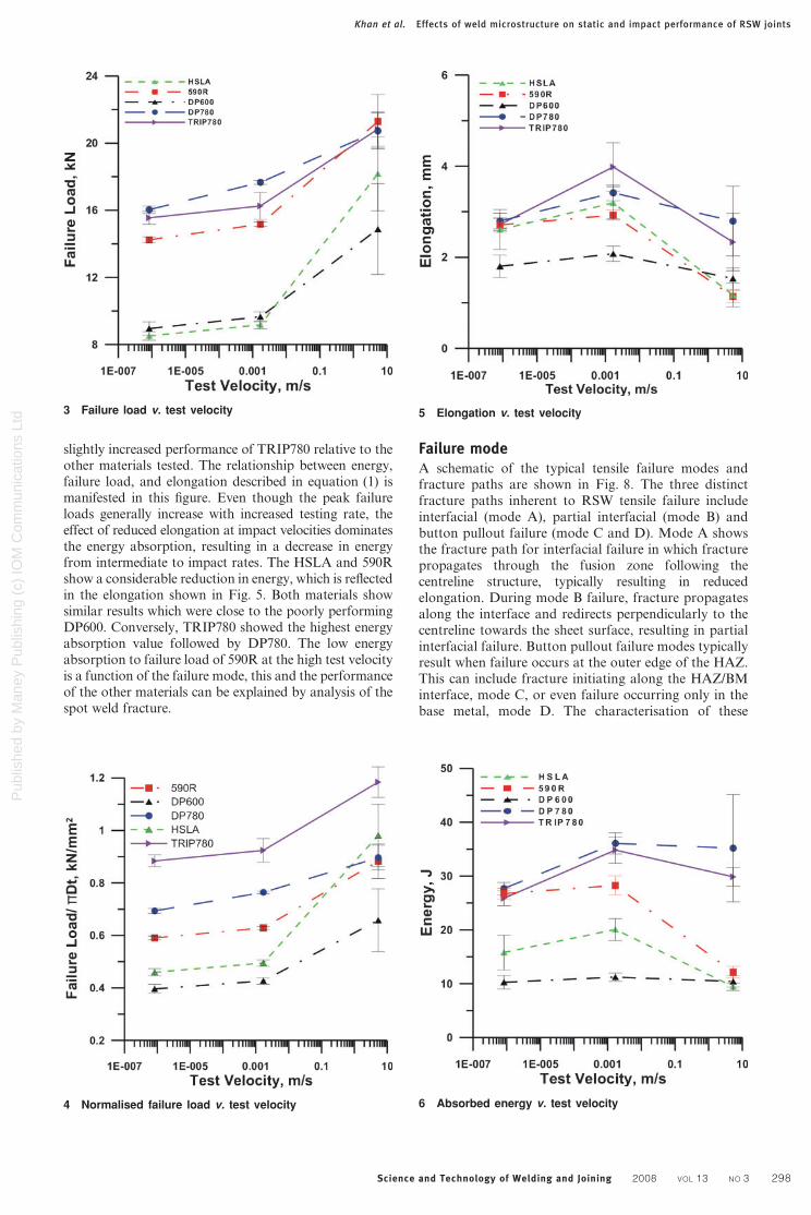
Pub
lishe
d by
Man
ey P
ublis
hing
(c)
IOM
Com
mun
icat
ions
Ltd
a static b intermediate c impact d fracture cross-section11 Typical fractured coupon appearance for TRIP780 material
a static b intermediate c impact d fracture cross-section12 Typical fractured coupon appearance for DP780 material
Khan et al Effects of weld microstructure on static and impact performance of RSW joints
Science and Technology of Welding and Joining 2008 VOL 13 NO 3 301
Pub
lishe
d by
Man
ey P
ublis
hing
(c)
IOM
Com
mun
icat
ions
Ltd seen that mode C fracture occurred near the HAZ with
failure propagating through the base metal Furthermorelocalised necking occurs in BM of the upper sheet whichindicated localised plastic deformation
Heat affected zone softening is a noted issue whenwelding DP steels and has been cited for early fail-ure2021 Post weld tempering of martensite near theHAZ results in a local softened region Materials whichexhibit higher volume fractions of martensite are moresusceptible to HAZ softening due to the increasedvolume fraction of tempered martensite after weldingAs mentioned earlier compared to the DP600 the basematerial of this particular DP780 contained a largervolume fraction of BM martensite Richer chemistriescoupled with increased martensite volume fractionmakes the DP780 more susceptible to HAZ softeningFigure 13 shows the softened region in DP780 comparedto the 590R and DP600 alloys Furthermore Maryaet al17 examined the fracture modes for spot welded DPsteels using the RSW process In their study increasedsoftening in the HAZ was also reported for higher gradeDP steels The DP600 in the current study consistentlyproduced interfacial failure resulting in reduced elonga-tion and poor impact performance Tensile testing of theDP780 on the other hand consistently produced fullbutton failure modes which followed the HAZ softenedregion and resulting in one of the best impact performanceresults Hence the inherent nature of DP softening inparticular for material containing higher volume fractionof martensite can potentially aid in improving impactperformance by producing ductile failure modes
The FB 590R steel spot welds showed a failure loadsimilar to the DP780 at impact test velocities howeverthe fracture toughness at high rates was more similar tothe DP600 The low energy absorption at high rates canbe explained by examining the failure mode Figure 14andashc shows the spot weld fracture surfaces for lowintermediate and high test velocities respectively Fullbutton pull-out failure modes during static and inter-mediate test velocities were observed the failure mode issimilar to the DP780 Mode D fracture initiated near theouter HAZ in the base metal and significant base metalnecking is observed in the partial tensile sample inFig 14d The fractured spot weld for the impact
conditions shown in Fig 14c reveals a unique fracturemorphology A lsquocomet-tailrsquo of material was observedshowing several segments of necked base metal Thisbehaviour is reflected in the high rate loadndashdisplacementcurve for 590R Figure 15 illustrates the unique beha-viour in which after initial fracture of the spot weldsignalled by a decrease in the measured load the loadincreased again up to a secondary peak slightly lowerthan the initial This cycle was repeated two times beforefinal fracture The comet-tail in Fig 14c shows threeregions of base metal necking that correspond to thepeaks observed in the high rate loadndashdisplacementcurve Ferriticndashbainitic steels typically have high strainhardening and high deformation These properties
13 Hardness traces from base metal to fusion zone for
DP780 DP600 and 590R
a static b intermediate c impact d fracture cross-section14 Typical fractured coupon appearance for 590R material
Khan et al Effects of weld microstructure on static and impact performance of RSW joints
Science and Technology of Welding and Joining 2008 VOL 13 NO 3 302
Pub
lishe
d by
Man
ey P
ublis
hing
(c)
IOM
Com
mun
icat
ions
Ltd
explain the impact failure observations after initialfracture around the spot weld tearing of the base metaloccurs The comet-tail material is strain hardenedpreventing fracture as shown by the secondary loadincrease The cycle of tearing and necking is repeateduntil final fracture occurs The energy absorbed by the590R spot weld continued to increase after the peak loadwas achieved until final fracture occurred
The typical method to calculate energy absorptionconsiders only elongation until the peak load isobtained Owing to the inherent strain hardeningbehaviour of the 590R the displacement to peak loadunder the impact condition is quite low Thus thecalculated impact toughness as shown in Fig 6 waspoor compared to the other materials such as DP780with a similar failure load However it was found thatafter surpassing the peak load there was continuedenergy absorption caused by tearing of the surroundingmaterial given by the total area under the loadndashdisplacement curve Calculating the total energyabsorbed during impact testing of the 590R results inan increase of the normalised value from 049 toy23 J mm22 surpassing the 17 J mm22 absorbed byTRIP780 Therefore it is suggested that the impactperformance of the FB type 590R material is compar-able to other types of AHSS The high peak loadcompared to the base metal strength is an indication ofhigh joint efficiency and the continued elongation afterthe peak load increases the total energy absorbed in acrash
Recent work comparing the impact performance of asreceived HSS and AHSS can be used as a basis tocompare spot weld impact performance Oliver et al22
showed that the primarily ferritic HSLA steel exhibitedthe greatest increase in strength with increasing strainrate while the predominately martensitic DP materialhad the least strain rate sensitivity Similarly Fig 4shows the HSLA spot welds having the greatest increasein load bearing capacity transitioning from intermediateto impact test velocities while the DP780 exhibitedthe least increase In a later publication by Oliver et al23
the energy absorption of TRIP and DP steel were
compared Results showed a greater increase in energyabsorption rate for the TRIP compared to the DPgrades of similar strength transitioning from static toimpact test velocities however the DP steel consistentlyabsorbed more energy These results however do notreflect those observed in Fig 7 where the spot weldedTRIP780 exhibited the highest energy absorptioncompared to the DP780 Discrepancies in results maybe attributed to the thermal history of spot weldedmaterial which modifies as received strip steel micro-structure typically resulting in a martensitic structure
It should also be recognised that various processingtechniques and chemistries used in AHSS productiondiffer from manufacturers which can also affect fracturemodes Hence the failure modes observed in theseparticular AHSS may not necessarily occur in othergrades which undergo different processing techniques
ConclusionsIn the present study the fracture surfaces and impactperformance of resistance spot welded AHSS wereexamined A comparison was conducted by observingfailure loads displacement energy absorption andfracture surfaces for static intermediate and impact testvelocities In addition performance results were normal-ised to compare relative material strength in the weldzone The followings are key results
1 Failure loads during tensile shear testing increasedas test velocities increased however there was nocorrelation between base metal strength and failureloads of the welds
2 Four different failure modes were observed Partialinterfacial failure was observed for the TRIP780 andHSLA where fracture propagated through the HAZand into the FZ during intermediate test velocities Twobutton pullout failure modes were obtained for 590Rand DP780 for all test velocities with failure near HAZfor DP780 and in base metal for 590R Interfacial failureconsistently occurred when testing DP600
3 Base metal failure occurs with the 590R duringstatic and intermediate test velocities however tearingwas observed when subjected to impact test velocitiesTearing can improve the energy absorption of 590R spotwelds if energy until fracture is calculated
4 Heat affected zone softening observed in DP780contributed to ductile pull-out failure modes as com-pared to the interfacial failure observed in the DP600thus resulting in poor impact performance by DP600
Acknowledgements
The authors would like to acknowledge the funding andsupport from Auto21 (wwwauto21ca) one of theNetworks of Centres for Excellence supported by theCanadian Government In addition material used inthis study was provided by the Auto Steel Partnership(ASP)
References1 I Khan M L Kuntz P Su A Gerlich T North and Y Zhou
Sci Technol Weld Join 2007 12 (2) 175ndash182
2 M Kimichi Weld J 1984 63 (2) 58sndash63s
3 K Banerjee and U K Chatterjee Metall Mater Trans A 2003
34A (6) 1297ndash1309
15 Loadndashdisplacement curves for 590R
Khan et al Effects of weld microstructure on static and impact performance of RSW joints
Science and Technology of Welding and Joining 2008 VOL 13 NO 3 303
Pub
lishe
d by
Man
ey P
ublis
hing
(c)
IOM
Com
mun
icat
ions
Ltd
4 S Dinda C Belleau and D K Kelley lsquoHigh strength low alloy
steel in automotive structuresrsquo 475ndash483 1984 Metals Park OH
ASM
5 J Dufourny and A Bragard Weld World 1985 23 (5ndash6) 100ndash
123
6 K W Ewing M Cheresh R Thompson and P Kukuchek lsquoStatic
and impact strengths of spot-welded HSLA and low carbon steelrsquo
SAE technical paper 820281 1982
7 W Peterson and F Orth Proc Sheet Metal Welding Conf XII
Livonia MI USA May 2006
8 A Pichler S Traint G Amoldner P Stiaszny M Blaimschein E
A Werner Proc 44th MWSP Conf Vol XL 2002 Warrendale
PA Iron and Steel Society
9 lsquoAutomotive steel design manualrsquo Revision 61 AISIASP August
2002
10 lsquoRecommended practices for evaluating the resistance spot welding
behaviour of automotive sheet steel materialsrsquo ANSIAWSSAE
1997
11 W Tan Y Zhou H W Kerr and S Lawson J Phys D 2004
37D (14) 1998ndash2008
12 C Ma S D Bhole D L Chen A Lee E Biro G Boudreau Sci
Technol Weld Join 2006 11 (4) 480ndash487(8)
13 H Zhang and J Senkara lsquoResistance welding fundamentals and
applicationsrsquo 2006 Boca Raton FL Taylor amp Frances
14 G B Frommeyer and P Neumann ISIJ Int 2003 43 (3) 438ndash446
15 N D Beynon T B Jones and G Fourlaris Mater Sci Technol
2005 21 (1) 103ndash112
16 N D Beynon S Oliver T B Jones and G Fourlaris Mater Sci
Technol 2005 21 (7) 771ndash778
17 M Marya K Wang L G Hector and X Gayden J Manuf Sci
Eng 2006 128 287ndash298
18 N Uijl and S Smith Proc 4th Int Semin on lsquoAdvances in
resistance weldingrsquo Wels Austria November 2006 SWANTEC
FRONIUS 30ndash62
19 E Girault A Mertens P Jacques Y Houbaert B Verlinden and
J V Humbeeck Scr Mater 2001 44 885ndash892
20 E Biro and A Lee Proc SMWC XII American Welding Society
(AWS) Livonia MI USA May 2006
21 M Xia N Sreenivasan S Lawson Y Zhou and Z Tian J Mater
Sci Eng 2007 129 446ndash452
22 S Oliver T B Jones and G Fourlaris Mater Sci Technol 2007
23 (1) 55ndash62
23 S Oliver T B Jones and G Fourlaris Mater Sci Technol 2007
23 (4) 423ndash431
Khan et al Effects of weld microstructure on static and impact performance of RSW joints
Science and Technology of Welding and Joining 2008 VOL 13 NO 3 304

Pub
lishe
d by
Man
ey P
ublis
hing
(c)
IOM
Com
mun
icat
ions
Ltd
4 S Dinda C Belleau and D K Kelley lsquoHigh strength low alloy
steel in automotive structuresrsquo 475ndash483 1984 Metals Park OH
ASM
5 J Dufourny and A Bragard Weld World 1985 23 (5ndash6) 100ndash
123
6 K W Ewing M Cheresh R Thompson and P Kukuchek lsquoStatic
and impact strengths of spot-welded HSLA and low carbon steelrsquo
SAE technical paper 820281 1982
7 W Peterson and F Orth Proc Sheet Metal Welding Conf XII
Livonia MI USA May 2006
8 A Pichler S Traint G Amoldner P Stiaszny M Blaimschein E
A Werner Proc 44th MWSP Conf Vol XL 2002 Warrendale
PA Iron and Steel Society
9 lsquoAutomotive steel design manualrsquo Revision 61 AISIASP August
2002
10 lsquoRecommended practices for evaluating the resistance spot welding
behaviour of automotive sheet steel materialsrsquo ANSIAWSSAE
1997
11 W Tan Y Zhou H W Kerr and S Lawson J Phys D 2004
37D (14) 1998ndash2008
12 C Ma S D Bhole D L Chen A Lee E Biro G Boudreau Sci
Technol Weld Join 2006 11 (4) 480ndash487(8)
13 H Zhang and J Senkara lsquoResistance welding fundamentals and
applicationsrsquo 2006 Boca Raton FL Taylor amp Frances
14 G B Frommeyer and P Neumann ISIJ Int 2003 43 (3) 438ndash446
15 N D Beynon T B Jones and G Fourlaris Mater Sci Technol
2005 21 (1) 103ndash112
16 N D Beynon S Oliver T B Jones and G Fourlaris Mater Sci
Technol 2005 21 (7) 771ndash778
17 M Marya K Wang L G Hector and X Gayden J Manuf Sci
Eng 2006 128 287ndash298
18 N Uijl and S Smith Proc 4th Int Semin on lsquoAdvances in
resistance weldingrsquo Wels Austria November 2006 SWANTEC
FRONIUS 30ndash62
19 E Girault A Mertens P Jacques Y Houbaert B Verlinden and
J V Humbeeck Scr Mater 2001 44 885ndash892
20 E Biro and A Lee Proc SMWC XII American Welding Society
(AWS) Livonia MI USA May 2006
21 M Xia N Sreenivasan S Lawson Y Zhou and Z Tian J Mater
Sci Eng 2007 129 446ndash452
22 S Oliver T B Jones and G Fourlaris Mater Sci Technol 2007
23 (1) 55ndash62
23 S Oliver T B Jones and G Fourlaris Mater Sci Technol 2007
23 (4) 423ndash431
Khan et al Effects of weld microstructure on static and impact performance of RSW joints
Science and Technology of Welding and Joining 2008 VOL 13 NO 3 304