
EFFECTS OF INTERFERENCES IN UHF RFID SYSTEMS · PDF fileEFFECTS OF INTERFERENCES IN UHF RFID...
19
Progress In Electromagnetics Research, PIER 98, 425–443, 2009 EFFECTS OF INTERFERENCES IN UHF RFID SYSTEMS A. Lazaro, D. Girbau, and R. Villarino Department of Electronics, Electrics and Automatics Engineering Universitat Rovira i Virgili (URV) Av. Pa¨ ısos Catalans 26, Campus Sescelades, Tarragona 43007, Spain Abstract—The Radio Frequency Identification (RFID) applications are growing rapidly, especially in the UHF frequency band that is being used in inventory management. Passive UHF tags are preferred for these applications. In this paper, RFID reader-to-reader interference is analyzed. A model to estimate the minimum distance between readers to achieve a desired probability of detection in real multipath environments is derived and compared to the ideal case (AWGN channel). Diversity techniques to combat multipath and interference effects are proposed and studied. 1. INTRODUCTION Nowadays there is a significant thrust in RFID use for improving the efficiency of inventory tracking and management in enterprise supply chain management [1–3]. These applications use passive RFID tags, which communicate with the reader by changing (modulating) its reflection coefficient to incoming radiation from the reader, i.e., modulating its scattering/radar cross section. For long-range tags, the UHF bands are often selected. In free space (i.e., with no environmental effects and far away from the source) the RF power density drops off as 1/r 2 , where r is the tag-reader distance. However, for multipath situations (this is the RFID case), with reflections and losses, the drop-off exponent n is situation dependent [4]. Three types of interferences can be considered in a RFID system: tag-to-tag interference, reader-to-tag interference and reader-to-reader interference. The tag-to-tag interference occurs when multiple tags respond to the same reader simultaneously. It can be avoided by Corresponding author: A. Lazaro ([email protected]).
Transcript of EFFECTS OF INTERFERENCES IN UHF RFID SYSTEMS · PDF fileEFFECTS OF INTERFERENCES IN UHF RFID...
Progress In Electromagnetics Research, PIER 98, 425–443, 2009
EFFECTS OF INTERFERENCES IN UHF RFID SYSTEMS
A. Lazaro, D. Girbau, and R. Villarino
Department of Electronics, Electrics and Automatics EngineeringUniversitat Rovira i Virgili (URV)Av. Paısos Catalans 26, Campus Sescelades, Tarragona 43007, Spain
Abstract—The Radio Frequency Identification (RFID) applicationsare growing rapidly, especially in the UHF frequency band that is beingused in inventory management. Passive UHF tags are preferred forthese applications. In this paper, RFID reader-to-reader interferenceis analyzed. A model to estimate the minimum distance betweenreaders to achieve a desired probability of detection in real multipathenvironments is derived and compared to the ideal case (AWGNchannel). Diversity techniques to combat multipath and interferenceeffects are proposed and studied.
1. INTRODUCTION
Nowadays there is a significant thrust in RFID use for improvingthe efficiency of inventory tracking and management in enterprisesupply chain management [1–3]. These applications use passive RFIDtags, which communicate with the reader by changing (modulating)its reflection coefficient to incoming radiation from the reader, i.e.,modulating its scattering/radar cross section. For long-range tags,the UHF bands are often selected. In free space (i.e., with noenvironmental effects and far away from the source) the RF powerdensity drops off as 1/r2, where r is the tag-reader distance. However,for multipath situations (this is the RFID case), with reflections andlosses, the drop-off exponent n is situation dependent [4].
Three types of interferences can be considered in a RFID system:tag-to-tag interference, reader-to-tag interference and reader-to-readerinterference. The tag-to-tag interference occurs when multiple tagsrespond to the same reader simultaneously. It can be avoided by
Corresponding author: A. Lazaro ([email protected]).
426 Lazaro, Girbau, and Villarino
having each tag responding at different times. Thus, a multi-tag anti-collision algorithm is needed to resolve this interference. Reader-to-taginterference occurs when a tag is in the interrogation zone of multiplereaders and more than one reader transmits simultaneously.
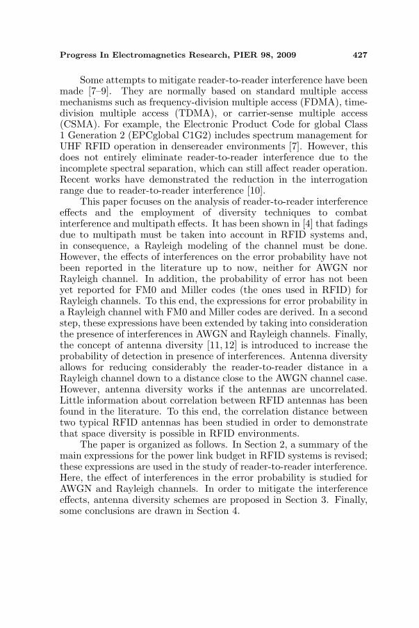
The third interference type is between readers and occurs whenthe signals from neighboring readers interfere (see Figure 1). It canbe avoided only by having neighboring readers operating at differenttimes or different frequencies. A multi-reader anti-collision algorithmmust be used to resolve this interference.
Serious reader-to-reader interference problems may exist in somedeployments (such as supply chains) where tens or hundreds of readersare in operation within a close range to each other. The distanceover which a reader can interfere with another reader is much largerthan the tag read range, particularly if high-gain reader antennas vieweach other. Reader-to-reader interference is a problem when signalstransmitted from distant readers are strong enough to impede accuratedecoding of the backscattered signals at the tags. The most basicsolution to reader-to-reader interference is to turn off the reader whenit is not needed by using sensors for reader activation. In the UnitedStates, roughly 50 hopping channels are available in the 902–928MHzISM band [5], and interference is sporadic until tens of readers arein simultaneous operation in a single facility, a situation that is notcommon yet. However, other jurisdictions provide much narrowerbands for RFID operation: ETSI EN 302 208 [6] allows only 2 MHz(865.6–867.6), Hong Kong allows 8MHz split into two bands, Singaporeallows 5MHz split into two bands and Korea allows 5.5 MHz. In theseregions interference is much more likely to be a problem, especiallywhen large facilities are considered.
Reader 1 Reader 2
Reader 2 Read RangeReader 1 Read Range
Interference Range
Figure 1. Reader-to-reader interference.
Progress In Electromagnetics Research, PIER 98, 2009 427
Some attempts to mitigate reader-to-reader interference have beenmade [7–9]. They are normally based on standard multiple accessmechanisms such as frequency-division multiple access (FDMA), time-division multiple access (TDMA), or carrier-sense multiple access(CSMA). For example, the Electronic Product Code for global Class1 Generation 2 (EPCglobal C1G2) includes spectrum management forUHF RFID operation in densereader environments [7]. However, thisdoes not entirely eliminate reader-to-reader interference due to theincomplete spectral separation, which can still affect reader operation.Recent works have demonstrated the reduction in the interrogationrange due to reader-to-reader interference [10].
This paper focuses on the analysis of reader-to-reader interferenceeffects and the employment of diversity techniques to combatinterference and multipath effects. It has been shown in [4] that fadingsdue to multipath must be taken into account in RFID systems and,in consequence, a Rayleigh modeling of the channel must be done.However, the effects of interferences on the error probability have notbeen reported in the literature up to now, neither for AWGN norRayleigh channel. In addition, the probability of error has not beenyet reported for FM0 and Miller codes (the ones used in RFID) forRayleigh channels. To this end, the expressions for error probability ina Rayleigh channel with FM0 and Miller codes are derived. In a secondstep, these expressions have been extended by taking into considerationthe presence of interferences in AWGN and Rayleigh channels. Finally,the concept of antenna diversity [11, 12] is introduced to increase theprobability of detection in presence of interferences. Antenna diversityallows for reducing considerably the reader-to-reader distance in aRayleigh channel down to a distance close to the AWGN channel case.However, antenna diversity works if the antennas are uncorrelated.Little information about correlation between RFID antennas has beenfound in the literature. To this end, the correlation distance betweentwo typical RFID antennas has been studied in order to demonstratethat space diversity is possible in RFID environments.
The paper is organized as follows. In Section 2, a summary of themain expressions for the power link budget in RFID systems is revised;these expressions are used in the study of reader-to-reader interference.Here, the effect of interferences in the error probability is studied forAWGN and Rayleigh channels. In order to mitigate the interferenceeffects, antenna diversity schemes are proposed in Section 3. Finally,some conclusions are drawn in Section 4.
428 Lazaro, Girbau, and Villarino
2. EFFECTS OF INTERFERENCES
2.1. Radio Link Budget in RFID Systems
A typical UHF RFID system consists of a reader and several passivetags. In the forward link communication (addressed as uplink), thereader interrogates the tag with a data transfer that utilizes an ASKmodulation scheme; the return data transfer, from tag to reader(addressed as downlink), utilizes a backscattered modulation scheme.In the uplink communication, the carrier signal generated by the readeris radiated out through the antenna. The tag collects energy from theelectromagnetic waves coming from the reader and converts it to DCsupply for the chip. Once the tag is powered up, the reader sends thecommands by modulating its carrier. After commands are completed,the reader sends an un-modulated continuous wave (CW) signal whichis used to provide DC supply for the tag. The power available to thetag for operation (Pr,tag) is given by a modification of Friis transmissionequation [4].
In the downlink communication, the tag responds to the readerand the reader must demodulate the signal. The selected tags encodethe data and then change the impedance of its antenna by modulatingthe radar cross section. The power received by the reader in thebackscatter communication radio link (Pr,reader ) is a modification ofthe monostatic radar equation:
Pr,reader (dBm) = Preader (dBm) + 2Greader (dB)− 2Lsys(dB)+20 log
∣∣ρ′∣∣ + 2Gtag(dB) + 2∆G(dB)− 2Lp (1)
where Preader is the power transmitted by the reader, Greader is the gainof the reader antenna, and Gtag is the nominal gain of the tag antenna.The term ∆G includes the gain penalty caused by detuning and thegain reduction when the tag is in contact with materials [4]. Lsys isthe cable loss, Lp is the path loss and ρ′ is the differential reflectioncoefficient of the tag ρ′ = ρ1−ρ2, where ρ1 and ρ2 are the 0 and 1 statesof the chip reflection coefficient, which depends on the chip load).
An empirical model for path loss is often used in indoorenvironments such as RFID. It is based on a two-slope model [4]:
LP (dB)=−20 log(
λ
4π
)+n110 log(r)+(α−n1)10 log(1+r/R0)+Lobs(dB)
(2)where r is the distance between tag and reader, λ is the wavelength,n1 the path loss factor for r < R0 [13] and α is the path loss factorfor r > R0 (for flat earth model α = 4). Lobs is the loss due todiffraction and medium attenuation. In practice, for passive RFID,

Progress In Electromagnetics Research, PIER 98, 2009 429
R0 = 4h1h2/λ (where h1 and h2 are the reader and tag antennaheights, respectively) is longer than the maximum read range. Thus,model (2) can be simplified by taking into account only the first pathloss term n110 log(r). The path loss factor n1 depends on the antenna’sheight but it has been found experimentally that for typical RFIDenvironments it is close to 2 [4].
The tag sensitivity is defined as the minimum power needed forrectification of the incident RF power (power up process). For instance,for the commercial tag Impinj Monza Gen 2, sensitivity is about−11 dBm. This value is higher than reader sensibility. In consequence,readers in passive UHF systems need to transmit high power in orderto power up the tags. Thus, the interference signals from other readersmay be a problem in downlink communication where the backscatteredsignal level can be comparable to the interfering signals.
2.2. Interferences in RFID Regulations
There are two major protocols adopted by the worldwide industry inUHF passive RFID field, EPCglobal specifications [7] and ISO 18000-6 [14], which identify the interaction between tags and readers. Inaddition, to avoid harm to human health and frequency interferences,local regulations such as the definition of the electromagneticcompatibility and the radio spectrum must be implemented (ETSI302.208 in Europe [6] and FCC part 15 in US [5]). The requirements interms of modulation type and depth and transmission mask determinethe UHF RFID transmitter architecture.
To meet the different RFID protocols in the uplink, the readercan use Double-SideBand Amplitude Shift Keying (DBS-ASK), Phase-Reversal ASK (PR-ASK) and Single-SideBand ASK (SSB-ASK). TheEPC GEN 2 specification defines a number of options for the physicallayer in both downlink and uplink and the reader uses Pulse IntervalEncoding (PIE). The length of Data-0 is given in Taris, where a Tariis the time reference unit of signaling and takes values between 6.25µsand 25 µs. The length of Data-1 takes values between 1.5 and 2 Tari.
European regulations fix a Listen Before Talk access protocol;if a reader detects a signal on the channel where it intends totransmit, it switches to another free channel. Two cases couldbe considered: a single-reader environment or a multiple-readerenvironment. In the latter, the number of simultaneously operatingreaders is assumed to be lower than the number of available channels.When the number of operating readers is large compared to thenumber of available channels, the situation is defined as a dense readerenvironment. In such environment, certified readers must incorporatethe schemes defined in the EPC GEN 2 specification to minimise
430 Lazaro, Girbau, and Villarino
(a) (b)
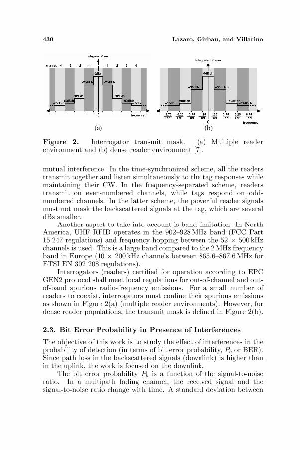
Figure 2. Interrogator transmit mask. (a) Multiple readerenvironment and (b) dense reader environment [7].
mutual interference. In the time-synchronized scheme, all the readerstransmit together and listen simultaneously to the tag responses whilemaintaining their CW. In the frequency-separated scheme, readerstransmit on even-numbered channels, while tags respond on odd-numbered channels. In the latter scheme, the powerful reader signalsmust not mask the backscattered signals at the tag, which are severaldBs smaller.
Another aspect to take into account is band limitation. In NorthAmerica, UHF RFID operates in the 902–928 MHz band (FCC Part15.247 regulations) and frequency hopping between the 52 × 500 kHzchannels is used. This is a large band compared to the 2 MHz frequencyband in Europe (10 × 200 kHz channels between 865.6–867.6 MHz forETSI EN 302 208 regulations).
Interrogators (readers) certified for operation according to EPCGEN2 protocol shall meet local regulations for out-of-channel and out-of-band spurious radio-frequency emissions. For a small number ofreaders to coexist, interrogators must confine their spurious emissionsas shown in Figure 2(a) (multiple reader environments). However, fordense reader populations, the transmit mask is defined in Figure 2(b).
2.3. Bit Error Probability in Presence of Interferences
The objective of this work is to study the effect of interferences in theprobability of detection (in terms of bit error probability, Pb or BER).Since path loss in the backscattered signals (downlink) is higher thanin the uplink, the work is focused on the downlink.
The bit error probability Pb is a function of the signal-to-noiseratio. In a multipath fading channel, the received signal and thesignal-to-noise ratio change with time. A standard deviation between
Progress In Electromagnetics Research, PIER 98, 2009 431
the model (2) and the measured received power of up to 4 dB wasexperimentally found in [4]. This value increases when the antennaheight decreases. Moreover, the received signal follows differentprobability functions depending on the scenario. The cover range as afunction of the scenario has been studied in [4].
In a multipath channel, an average signal-to-noise ratio must betaken into account to calculate the average Pb. However, in systemswith interferences, if the statistical distribution of the interference canbe approximated to that of Gaussian noise, the received average signal-to-interference-plus-noise power ratio (SINR) is often used instead ofthe average signal-to-noise ratio to calculate error probability. Inthose RFID systems operating according to EPC GEN2 protocol, theinterference can come from spurious emissions of all interfering readers,according to the transmit mask (see Figure 2). Moreover, interferentand interfered readers are not frequency-locked to the same clockreference and they can present frequency deviations. In addition, if thereaders operate in multiple reader environments or are not perfectlysynchronized in dense reader environments, the interfering signals arespurious and residual out-of-band modulated signals of the uplink. Byapplying the Central Limit Theorem to the interference, it can beapproximated as added Gaussian noise. Thus, the interfering signalsare uncorrelated with the backscattered signal at the tag and noise,and then the effective average signal-to-interference-plus-noise ratio(or SINR) γ is given by [15]:
γ =S
N + I=
11
SNR + 1CIR
(3)
where S is the average signal power, N is the noise power and I isthe average interference power. SNR is the average signal to noiseratio in an AWGN channel and CIR is the carrier-to-interference ratio(or SIR, signal-to-interference ratio). The effective average SINR (3)is the hyperbolic average between the signal-to-noise ratio and thesignal-to-interference ratio. It is approximately equal to CIR in aninterference-dominated scenario.
The CIR can be calculated from the difference between the powerreceived by the reader from the tag (1) and the interfering power PI ,which can be calculated from:
PI(dBm) = Preader,int(dBm)−ACPR(dB) + Greader,int(dB)+Greader(dB)− LP,int(dB) (4)
where Preader,int and Greader,int are the power transmitted by theinterfering reader and its antenna gain in the direction of the interferedreader, respectively. In (4), ACPR is the adjacent channel power ratio
432 Lazaro, Girbau, and Villarino
and it is determined by the transmission mask (see Figure 2). The pathloss between the interfering reader and the interfered reader LP,int isgiven by (2) but using the reader-to-reader distance. Fortunately, inthis case, this distance can be larger than R0 and the path loss maybe considerably high. In addition, losses due to obstacles may be veryimportant and can also reduce reader-to-reader interference.
The uplink data rate is partially determined by the downlinkpreamble and partially by a bit field set in the query command whichstarts each query round [7]. These settings allow for an uplink data rateranging from 40 kbps to 640 kbps. The reader sets the uplink frequencyand also sets one of the four uplink encodings, namely FM0, Miller-2,Miller-4 or Miller-8 (tag communicates with reader using either FM0 orMiller sub-carrier encoding). When using FM0, one bit is transmittedduring each cycle and a phase inversion occurs at the boundary betweensymbols while Data-0 has a mid-symbol phase inversion. FM0 is highlysusceptible to noise and interferences and this motivated the additionof the Miller encodings. While these are more robust to errors withthe increase of the number, their link rates are reduced by a factorof 2, 4 or 8, depending on the encoding. Reference [16] derives anexpression for bit error rate (BER) for FM0 and Miller encoding. Thisresult is only valid for an AWGN channel. If a symbol-by-symboldetection is applied, it is not optimal but it is easy to implementcompared to differential detection. When using a differential decodera 3-dB improvement is obtained [16]. The symbol error rate (SER)(or, equivalently, the BER) is given by [16]:
Pb = 2Q
(√MES
N0
)[1−Q
(√MES
N0
)](5)
where ES is the symbol energy, N0/2 is the noise power spectrumdensity of an AWGN channel, M is the Miller-code order, and Q(x)is the Q-function [17]. From the ES/N0 ratio, it can be easilyobtained the signal-to-noise ratio γ assuming that noise bandwidth isapproximately equal to 1/TS (where TS is the duration of a symbol):
γ = S/N ≈ESTS
N0TS
=ES
N0(6)
However, (5) is not generally valid in RFID environments,since due to multipath propagation, the signals follow a Rayleighdistribution in the worst case. Then, the average error probabilityPb is computed by integrating the error probability in AWGN over thefading distribution:
Progress In Electromagnetics Research, PIER 98, 2009 433
Pb =
∞∫
0
Pb(γ)fγ(γ)dγ (7)
where Pb(γ) is the probability of symbol error in AWGN with SNR γ,which can be obtained from (5) and fγ(γ) the probability density fora Rayleigh distribution of fading amplitude, which can be computedfrom:
fγ(γ) =1γ
e−γ/γ (8)
where γ is the effective average SINR (3). To evaluate the integral (7),the Q(x) function and Q2(x) can be written as [15]:
Q(x) =1π
π/2∫
0
e−x2
2 sin2 φ dφ (9)
Q2(x) =1π
π/4∫
0
e−x2
2 sin2 φ dφ (10)
Then, using (9), (10), the following new compact expression hasbeen obtained for the mean bit error rate in a Rayleigh channel:
Pb(γ) =12− 1√
1 + 2/(Mγ)+
2π
tan−1
(√1 + 2/(Mγ)
)
√1 + 2/(Mγ)
≈ 12Mγ
(11)
where the approximation holds for large γ; in this case, (11) is inverselyproportional to γ, identical to the BPSK case [15]. In addition, if adifferential decoder is used, (11) tends to the same limit as the BPSKcase (1/4γ).
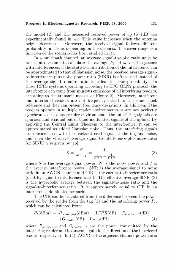
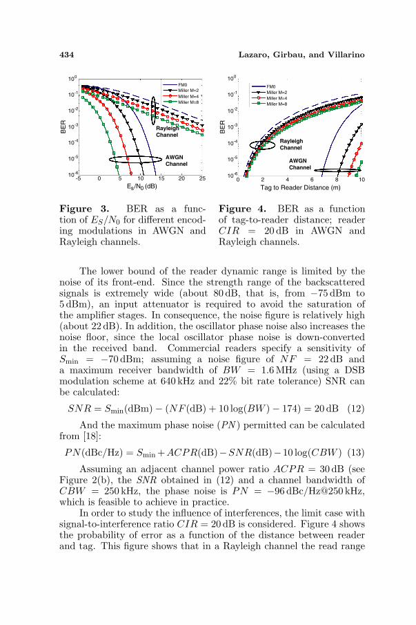
Figure 3 compares the BER performance of FM0 and Miller codesin ideal AWGN and Rayleigh channels. It is clear that for large signal-to-noise ratios the BER decreases faster in an AWGN channel thanin a Rayleigh channel. A SNR of approximately 12 dB is required tomaintain a 10−3 bit error rate in AWGN while a SNR of approximately25 dB is required in a Rayleigh channel when using FM0 encoding.It can also be deduced from (11) that the BER decreases with theincrease of the Miller sub-carrier order, but here the disadvantage isthe reduction in the data rate. From Figure 3 it is also clear thata technique is required to maximize the read range and remove theeffects of fading. Next section proposes antenna diversity to overcomethese limitations. It must be noted that Rayleigh fading is one of theworst-case scenarios.
434 Lazaro, Girbau, and Villarino
-5 0 5 10 15 20 2510-6
10-5
10-4
10-3
10-2
10-1
100
Es/N0 (dB)
BE
R
RayleighChannel
AWGNChannel
FM0
Miller M=2
Miller M=4
Miller M=8
Figure 3. BER as a func-tion of ES/N0 for different encod-ing modulations in AWGN andRayleigh channels.
10-6
10-5
10-4
10-3
10-2
10-1
100
BE
R
AWGN
Channel
Rayleigh
Channel
0 2 4 6 8 10
Tag to Reader Distance (m)
FM0
Miller M=2
Miller M=4
Miller M=8
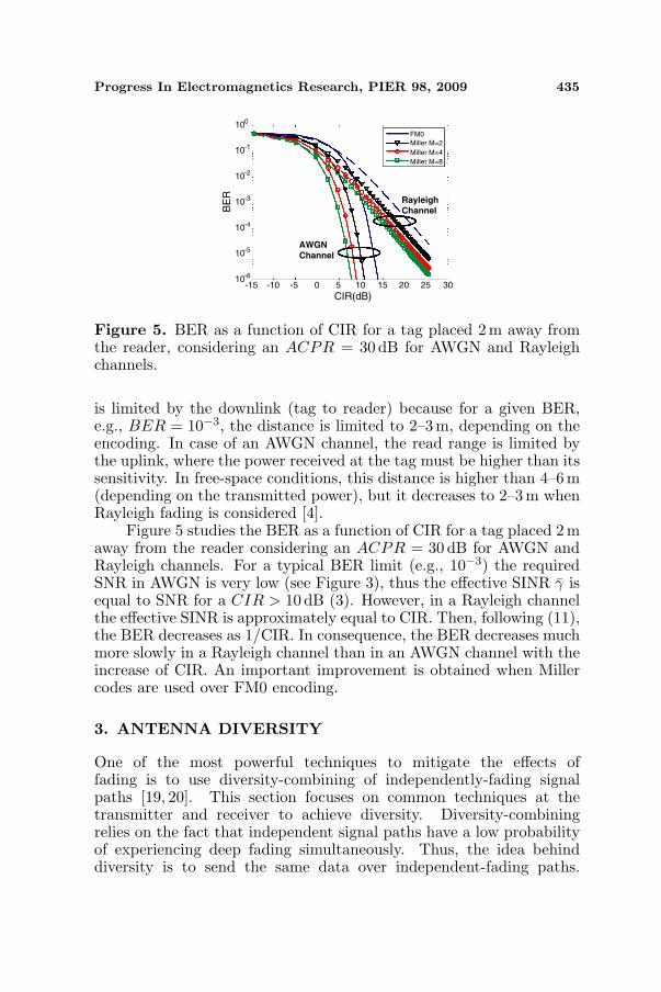
Figure 4. BER as a functionof tag-to-reader distance; readerCIR = 20 dB in AWGN andRayleigh channels.
The lower bound of the reader dynamic range is limited by thenoise of its front-end. Since the strength range of the backscatteredsignals is extremely wide (about 80 dB, that is, from −75 dBm to5 dBm), an input attenuator is required to avoid the saturation ofthe amplifier stages. In consequence, the noise figure is relatively high(about 22 dB). In addition, the oscillator phase noise also increases thenoise floor, since the local oscillator phase noise is down-convertedin the received band. Commercial readers specify a sensitivity ofSmin = −70 dBm; assuming a noise figure of NF = 22 dB anda maximum receiver bandwidth of BW = 1.6 MHz (using a DSBmodulation scheme at 640 kHz and 22% bit rate tolerance) SNR canbe calculated:
SNR = Smin(dBm)− (NF (dB) + 10 log(BW )− 174) = 20 dB (12)
And the maximum phase noise (PN ) permitted can be calculatedfrom [18]:
PN(dBc/Hz) = Smin +ACPR(dB)−SNR(dB)−10 log(CBW ) (13)
Assuming an adjacent channel power ratio ACPR = 30dB (seeFigure 2(b), the SNR obtained in (12) and a channel bandwidth ofCBW = 250 kHz, the phase noise is PN = −96 dBc/Hz@250 kHz,which is feasible to achieve in practice.
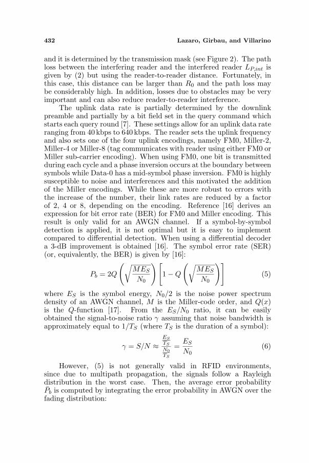
In order to study the influence of interferences, the limit case withsignal-to-interference ratio CIR = 20dB is considered. Figure 4 showsthe probability of error as a function of the distance between readerand tag. This figure shows that in a Rayleigh channel the read range
Progress In Electromagnetics Research, PIER 98, 2009 435
-15 -10 -5 0 5 10 15 20 25 3010
-6
10-5
10-4
10-3
10-2
10-1
100
CIR(dB)
BE
R
Rayleigh
Channel
AWGN
Channel
FM0
Miller M=2
Miller M=4
Miller M=8
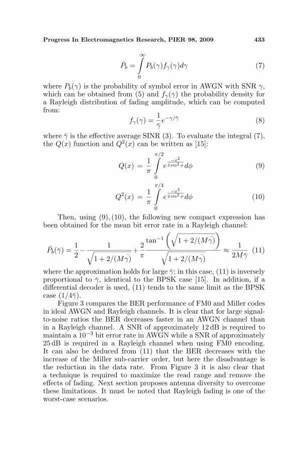
Figure 5. BER as a function of CIR for a tag placed 2 m away fromthe reader, considering an ACPR = 30 dB for AWGN and Rayleighchannels.
is limited by the downlink (tag to reader) because for a given BER,e.g., BER = 10−3, the distance is limited to 2–3 m, depending on theencoding. In case of an AWGN channel, the read range is limited bythe uplink, where the power received at the tag must be higher than itssensitivity. In free-space conditions, this distance is higher than 4–6 m(depending on the transmitted power), but it decreases to 2–3m whenRayleigh fading is considered [4].
Figure 5 studies the BER as a function of CIR for a tag placed 2 maway from the reader considering an ACPR = 30 dB for AWGN andRayleigh channels. For a typical BER limit (e.g., 10−3) the requiredSNR in AWGN is very low (see Figure 3), thus the effective SINR γ isequal to SNR for a CIR > 10 dB (3). However, in a Rayleigh channelthe effective SINR is approximately equal to CIR. Then, following (11),the BER decreases as 1/CIR. In consequence, the BER decreases muchmore slowly in a Rayleigh channel than in an AWGN channel with theincrease of CIR. An important improvement is obtained when Millercodes are used over FM0 encoding.
3. ANTENNA DIVERSITY
One of the most powerful techniques to mitigate the effects offading is to use diversity-combining of independently-fading signalpaths [19, 20]. This section focuses on common techniques at thetransmitter and receiver to achieve diversity. Diversity-combiningrelies on the fact that independent signal paths have a low probabilityof experiencing deep fading simultaneously. Thus, the idea behinddiversity is to send the same data over independent-fading paths.
436 Lazaro, Girbau, and Villarino
...
Antenna 1
Antenna N
READER
...
Antenna 1
Antenna N
READER
a1
aM
(a) (b)
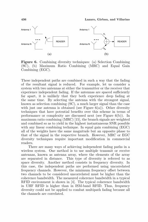
Figure 6. Combining diversity techniques: (a) Selection Combining(SC), (b) Maximum Ratio Combining (MRC) and Equal GainCombining (EGC).
These independent paths are combined in such a way that the fadingof the resultant signal is reduced. For example, let us consider asystem with two antennas at either the transmitter or the receiver thatexperience independent fading. If the antennas are spaced sufficientlyfar apart, it is unlikely that they both experience deep fading atthe same time. By selecting the antenna with the strongest signal,known as selection combining (SC), a much larger signal than the casewith just one antenna is obtained (see Figure 6(a)). Other diversitytechniques that have potential benefits over this scheme in terms ofperformance or complexity are discussed next (see Figure 6(b)). Inmaximum ratio combining (MRC) [15], the branch signals are weightedand combined so as to yield in the highest instantaneous SNR possiblewith any linear combining technique. In equal gain combining (EGC)all of the weights have the same magnitude but an opposite phase tothat of the signal in the respective branch. However, MRC or EGCdiversity techniques require important modification in commercialreaders.
There are many ways of achieving independent fading paths in awireless system. One method is to use multiple transmit or receiveantennas, known as antenna array, where the elements of the arrayare separated in distance. This type of diversity is referred to asspace diversity. Another method consists in frequency diversity. Inthis case, the independent paths are performed using uncorrelatedfrequency channels. However, the minimum frequency offset betweentwo channels to be considered uncorrelated must be higher than thecoherence bandwidth. The measured coherence bandwidth in a typicalRFID environment is shown in [4]. The typical coherence bandwidthin UHF RFID is higher than in ISM-band RFID. Thus, frequencydiversity could not be applied to combat multipath fading because allthe channels are correlated.
Progress In Electromagnetics Research, PIER 98, 2009 437
0 0.5 1 1.5 2 2.5 3-100
-80
-60
-40
-20
0
d/
e(d
B)
Patch antenna
Dipole antenna
λ
ρ
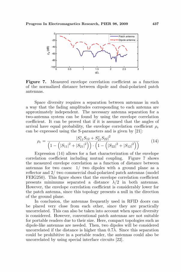
Figure 7. Measured envelope correlation coefficient as a functionof the normalized distance between dipole and dual-polarized patchantennas.
Space diversity requires a separation between antennas in sucha way that the fading amplitudes corresponding to each antenna areapproximately independent. The necessary antenna separation for atwo-antenna system can be found by using the envelope correlationcoefficient. It can be proved that if it is assumed that the angles ofarrival have equal probability, the envelope correlation coefficient ρe
can be expressed using the S-parameters and is given by [21]:
ρe =|S∗11S12 + S∗21S22|2(
1−(|S11|2 + |S21|2
))·(1−
(|S22|2 + |S12|2
)) (14)
Expression (14) allows for a fast characterization of the envelopecorrelation coefficient including mutual coupling. Figure 7 showsthe measured envelope correlation as a function of distance betweenantennas for two cases: 1/ two dipoles with a ground plane as areflector and 2/ two commercial dual-polarized patch antennas (modelFEIG250). This figure shows that the envelope correlation coefficientpresents minimums separated a distance λ/2 in both antennas.However, the envelope correlation coefficient is considerably lower forthe patch antenna, since this topology presents a null in the directionof the ground plane.
In conclusion, the antennas frequently used in RFID doors canbe placed very close from each other, since they are practicallyuncorrelated. This can also be taken into account when space diversityis considered. However, conventional patch antennas are not suitablefor portable readers due to their size. Here, compact topologies such asdipole-like antennas are needed. Then, two dipoles will be considereduncorrelated if the distance is higher than 0.7λ. Since this separationcould be prohibitive in a portable reader, the antennas could also beuncorrelated by using special interface circuits [22].
438 Lazaro, Girbau, and Villarino
After the study of practical viability of space diversity in UHFRFID systems, the performance of selecting combining technique isinvestigated. In selection combining, the combiner outputs the signalon the branch with the highest SNR. Assuming a stationary scenario,for a N -branch diversity, the Complementary Distribution Function(CDF) of the average signal-to-noise-ratio γΣ is given by [15]:
PγΣ(γ)=p(γΣ <γ)=p(max[γ1, γ2, . . . , γN ]<γ)=N∏
i=1
p(γi <γ) (15)
Defining the average SNR in the ith branch as γi = E[γi], theSNR distribution is exponential and it is given by (8) with γ = γi. Ifthe average SNR for all the branches is the same γ = γi, then (15)reduces to:
PγΣ(γ) = p(γΣ < γ) =N∏
i=1
(1− e−γ/γi) =(1− e−γ/γ)N (16)
Differentiating (16) relative to γ yields the probability distributionfunction for γΣ:
fγΣ(γ) =N
γ
[1− e−γ/γ
]N−1e−γ/γ (17)
Then, the mean error probability in selection combining diversityPb,SC can be calculated using:
Pb,SC =
∞∫
0
Pb(γ)fγΣ(γ)dγ (18)
Finally, using (9), (10), a new compact expression for (18) isobtained:
Pb,SC = NN−1∑
n=0
(−1)n
n + 1
(N − 1
n
)Pb
(γ
n + 1
)(19)
where the function Pb is given by the average Rayleigh errorprobability (11). Equation (19) has been checked by means ofnumerical integration.
Figures 8, 9 study the effects of diversity in presence of interferenceby calculating the BER as a function of distance between the interferingreader and the interfered reader for an AWGN channel, a Rayleighchannel and a Rayleigh channel with antenna diversity of order N = 2.The tag is located 2 m away from the interfered reader. According tothe transmit mask for dense reader environment (Figure 2(b)), it is

Progress In Electromagnetics Research, PIER 98, 2009 439
10 20 30 40 50 60 70 80 90 100
Reader to reader distance (m)
10-6
10-5
10-4
10-3
10-2
10-1
100
BE
R
AWGN
Channel
Rayleigh
ChannelDiversity
N=2
FM0
Miller M=2
Miller M=4
Miller M=8
Figure 8. BER as a functionof reader-to-reader distance for anAWGN channel and a Rayleighchannel using antenna diversityof order 2, with interference andconsidering an ACPR of 30 dB.
10 20 30 40 50 60 70 80 90 100
Reader to reader distance (m)
10-6
10-5
10-4
10-3
10-2
10-1
100
BE
R
FM0
Miller M=2
Miller M=4
Miller M=8RayleighChannel
RayleighChannel
Diversity
N=2
Figure 9. BER as a functionof reader-toreader distance for aRayleigh channel and a Rayleighchannel using antenna diversityof order 2, with interference andconsidering an ACPR of 30 dB.
assumed that in the worst case the interference falls just at the adjacentchannel, the ACPR in (4) amounts to 30 dB and the reader antennasare one in front of the other. In this case, for an error probability of10−4, the minimum reader-to-reader distance can be up to 10–25 m inan ideal AWGN channel; however, in a Rayleigh channel, readers asfar as 100m could degrade the BER in RFID systems. Using antennadiversity with only 2 branches, this minimum distance can be reduceddown to about 30 m (using Miller encoding). It can be concluded thata diversity technique as simple as SC with two branches aids to solvethe problem of interferences.
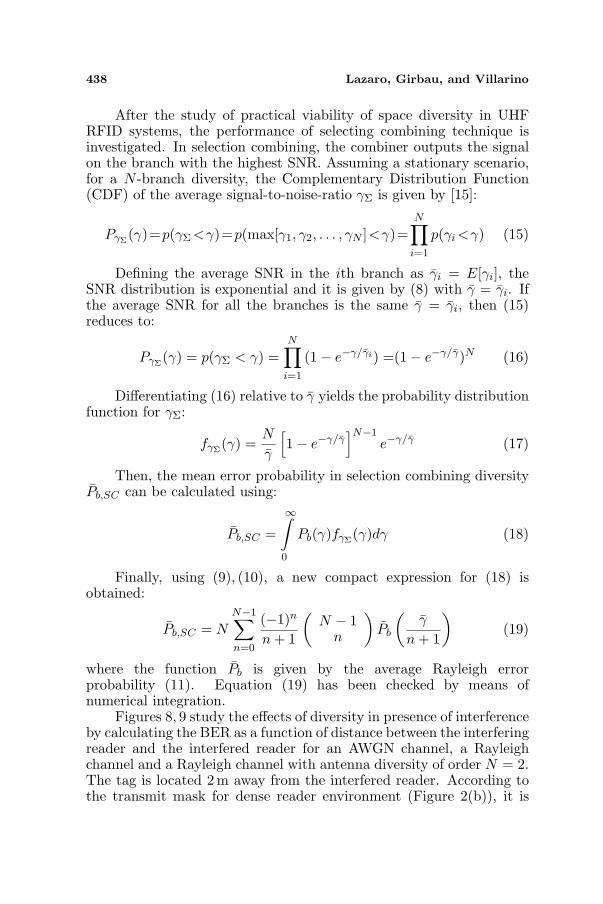
Figures 10, 11 show the BER as a function of CIR for anAWGN channel, a Rayleigh channel and a Rayleigh channel withantenna diversity considering an ACPR of 30 dB and a tag 2 m awayfrom the interfered reader. These figures, as well as Figures 8, 9,demonstrate that the utilization of an antenna diversity technique assimple as selection combining is fundamental to achieve high-detectionprobability in dense reader environments. An increase in the CIRcould be obtained by blocking the interference with absorbing materialsor metallic walls. This extra increase in the path attenuation wouldallow reducing the reader-to-reader distance below 30m. However, thisseems to be a very unpractical solution. A CIR reduction of about 5–6 dB could be achieved by increasing the number of antennas from 2to 4, which corresponds to a reduction to a half of the reader-to-readerminimum distance.
440 Lazaro, Girbau, and Villarino
-15 -10 -5 0 5 10 15 20 25 3010
-6
10-5
10-4
10-3
10-2
10-1
100
CIR(dB)
BE
R
FM0
Miller M=2
Miller M=4
Miller M=8
Figure 10. BER as a functionof CIR for an AWGN channel anda Rayleigh channel with antennadiversity of order 2.
-15 -10 -5 0 5 10 15 20 25 3010
-6
10-5
10-4
10-3
10-2
10-1
100
CIR(dB)
BE
R
FM0
Miller M=2
Miller M=4
Miller M=8
Figure 11. BER as a functionof CIR for a Rayleigh channelwithout antenna diversity and aRayleigh channel with antennadiversity of order 2 and 4.
0 50 1000
50
100
150
200
Number of Interfering Readers
Reader-
to-R
eade
r
Dis
tance (
m)
(a)
0 50 1000
200
400
600
800
1000
Number of Interfering Readers
Reader-
to-R
eade
r D
ista
nce (
m)
(b)
0 50 1000
100
200
300
400
Number of Interfering Readers
Reader-
to-R
eade
r
Dis
tance (
m)
(c)
0 50 1000
50
100
150
200
Number of Interfering Readers
Reader-
to-R
eade
rD
ista
nce (
m)
(d)
FM0
Miller M=2
Miller M=4
Miller M=8
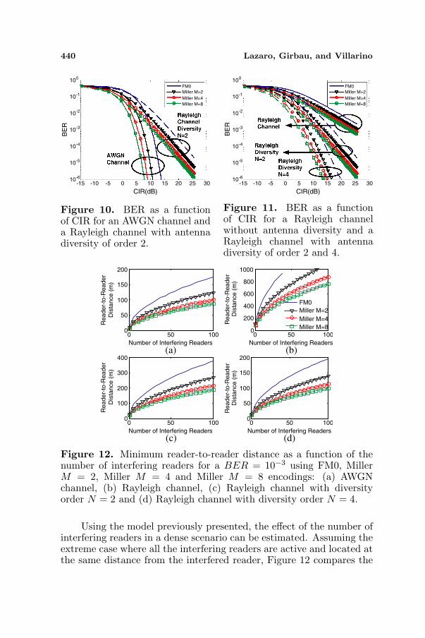
Figure 12. Minimum reader-to-reader distance as a function of thenumber of interfering readers for a BER = 10−3 using FM0, MillerM = 2, Miller M = 4 and Miller M = 8 encodings: (a) AWGNchannel, (b) Rayleigh channel, (c) Rayleigh channel with diversityorder N = 2 and (d) Rayleigh channel with diversity order N = 4.
Using the model previously presented, the effect of the number ofinterfering readers in a dense scenario can be estimated. Assuming theextreme case where all the interfering readers are active and located atthe same distance from the interfered reader, Figure 12 compares the
Progress In Electromagnetics Research, PIER 98, 2009 441
minimum reader-to-reader distance permitted to obtain a bit error rate(BER = 10−3) using FM0, Miller M = 2, Miller M = 4 and MillerM = 8 encodings. From these results, it is clear that the minimumpermitted reader-to-reader distance decreases with the increase of theencoding order M . It is also clear that, by increasing the antennadiversity order, minimum reader-to-reader distances in a Rayleighchannel similar to the ones in an AWGN channel can be recovered.
4. CONCLUSIONS
In this paper, the effect of reader-to-reader interference in RFIDsystems has been studied. Indoor wireless systems, such asRFID systems, are seriously affected by fadings due to multipathpropagation. In these scenarios the channel is far from an idealAWGN channel. The received power changes with time and followsa Rayleigh distribution. In this paper, expressions to evaluate theerror probability for FM0 and Miller codes (the ones used in RFID) inRayleigh channels have been derived. Then, the effects of interferencesin (ideal) AWGN and (real) Rayleigh channels are compared. The useof antenna diversity schemes has been proposed in order to mitigatethe read range reduction due to reader-to-reader interference. In thoseRFID applications where the tag position is not known (for instance,dock doors), space diversity is often used. By using several readerantennas, it is possible that one antenna is in line-of-sight with the tagand, in consequence, signal blocking is avoided. In addition, selectioncombining is often used in RFID systems to increase the number oftag reads. However, in this paper the concept of antenna diversity hasbeen introduced to increase the probability of detection in presenceof interferences. To this end, a new compact expression to model theprobability of error for FM0 and Miller codes in a Rayleigh channelhas been derived. It has been demonstrated that antenna diversityallows reducing considerably the reader-to-reader distance consideringa Rayleigh channel up to a minimum distance close to the ideal AWGNchannel case. Finally, the correlation distance between two typicalRFID antennas has been studied, demonstrating the viability of usingN -branch diversity in most RFID applications to combat reader-to-reader interference.
The design considerations and expressions given in this paperfor the calculation of bit error probability using FM0 and Millerencoding and considering a Rayleigh channel can be applied to developtools and simulators for prevision of interferences in dense-readerenvironments, serving as a useful guideline for RFID system-leveldesigners or engineers.
442 Lazaro, Girbau, and Villarino
ACKNOWLEDGMENT
This paper was supported by the Spanish Government ProjectTEC2008-06758-C02-02.
REFERENCES
1. Vita, G. D. and G. Iannaccone, “Design criteria for the RF sectionof UHF and microwave passive RFID transponders,” IEEE Trans.on Microwave Theory and Tech., Vol. 53, No. 9, 2978–2990, 2005.
2. Finkenzeller, K., RFID Handbook: Fundamentals and Applica-tions in Contactless Smart Cards and Identification, John Wiley& Sons, Chichester, 2003.
3. Fan, Z., S. Qiao, J. T. Huangfu, and L. X. Ran, “Signaldescriptions and formulations for long range UHF RFID readers,”Progress In Electromagnetics Research, PIER 71, 109–127, 2007.
4. Lazaro, A., D. Girbau, and D. Salinas, “Radio link budgetsfor UHF RFID on multipath environments,” IEEE Trans. onAntennas and Propagation, Vol. 57, No. 4, 1241–1251, 2009.
5. FCC Title 47, Part 15, “Operation within the bands 902–928 MHz,2435–2465MHz, 5785–5815 MHz, 10500–10550 MHz, and 24075–24175MHz”.
6. ETSI EN 302-208-1, “Electromagnetic compatibility and Radiospectrum Matters (ERM): Radio frequency identification equip-ment operating in the band 865 MHz to 868MHz with power lev-els up to 2 W, Part 1: Technical requirements and methods ofmeasurement,” July 2007.
7. EPCglobal, Inc., “EPCTM radio-frequency identity protocolsClass-1 Generation-2 UHF RFID protocol for communications at860–960MHz,” Ver. 1.0.9, Jan. 2005.
8. Cha, K., A. Ramachandran, and S. Jagannathan, “Adaptive andprobabilistic power control alogrithms for dense RFID readernetwork,” Proceedings of the 2006 IEEE International Conferenceon Networking, Sensing and Control (ICNSC’06), 474–479, 2006.
9. Seong, Y.-R., et al, “Arbitration of UHF-band mobile readers,”Proceedings of the 6th International Conference on Applicationsand Principles of Information Science (APIS 06), 20–21, 2007.
10. Kim, D. Y., H.-G. Yoon, B.-J. Jang, and J.-G. Yook, “Interferenceanalysis of UHF RFID systems,” Progress In ElectromaneticsResearch B, Vol. 4, 115–126, 2008.
11. Paulraj, A. J., D. A. Gore, R. U. Nabar, and H. Boelcskei, “An
Progress In Electromagnetics Research, PIER 98, 2009 443
overview of MIMO communications — A key to Gigabit wireless,”Proceedings of the IEEE, Vol. 92, No. 2, 198–218, 2004.
12. Abouda, A. A. and S. G. Haggman, “Effect of mutual couplingon capacity of MIMO wireless channels in high SNR scenario,”Progress In Electromagnetics Research, PIER 65, 27–40, 2006.
13. Xia, H. H., H. L. Bertoni, L. R. Maciel, A. Lindsay-Stewrt,and R. Rowe, “Radio propagation characteristics for line-of-sightmicrocellular and personal communications,” IEEE Trans. onAntennas and Propagation, Vol. 41, No. 10, 1439–1447, 1993.
14. JTC1, “Information technology-radio frequency identificationfor item management — Part 6: Parameters for air interfacecommunications at 860MHz to 960 MHz, AMENDMENT 1:Extension with Type C and update of Types A and B,” I.ISO/IEC, 2006.
15. Goldsmith, A., Wireless Communications, Cambridge UniversityPress, 2005.
16. Simon, M. and D. Divsalar, “Some interesting observationsfor certain line codes with application to RFID,” IEEE Trans.Communication, Vol. 54, No. 4, 583–586, 2006.
17. Proakis, J. G., Digital Communications, 3rd edition, McGraw-Hill, New York, 1995.
18. Bae, J. H., J. C. Kim, B. W. Jeon, J. W. Jung, J. S. Park,B. J. Jang, H. R. Oh, Y. J. Moon, and Y. R. Seong, “Analysisof phase noise requirements on local oscillator for RFID systemconsidering range correlation,” European Conference on WirelessTechnology (EcWT’07), 385–388, 2007.
19. Lee, W. C., “Antenna spacing requirement for a mobile radiobasestation diversity,” Bell Sys. Tech. J., Vol. 50, 1859–1876, 1971.
20. Clarke, R. H., “A statical theory of mobile-radio reception,” BellSyst. Tech. J., 957–1000, 1968.
21. Blanch, S., J. Romeu, and I. Corbella, “Exact representationof antenna system diversity performance from input parameterdescription,” IEE Electronics Letter, Vol. 39, No. 9, 705–707, 2003.
22. Leather, P. S. H. and D. Parsons, “Antenna diversity for UHFhand portable radio,” IEE Electronics Letters, Vol. 39, No. 13,946–948, 2003.


