Acrylics – layers and glazes ... · Acrylics – layers and glazes Abstract art

EFFECTIVENESS OF CONFORMAL COATINGS IN PREVENTING RESISTOR SILVER SULFIDE CORROSION
Marie Cole, Jacob Porter, Jason Wertz, Marc Coq IBM Corporation
Poughkeepsie, NY, USA [email protected]
Jim Wilcox and Mike Meilunas Universal Instruments Corporation
Conklin, NY, USA
ABSTRACT Thick film resistors are used extensively in a variety of electronics applications. The silver in a conventional thick film resistor is prone to the attack of sulfur-bearing gaseous contamination. This problem has been documented for servers that are found in data centers, due to the environmental pollution of sulfur in certain industrial locations and more typically, in growth market countries where the use of coal to produce electricity is prevalent.
The growth of silver sulfide, resulting from silver corrosion, can cause an increase in resistance and eventually, an electrical open of the resistor. The best method to increase the robustness of resistors in high sulfur environments is to employ Anti-Sulfur Resistors (ASR). These resistors either have a structure alteration to seal the ingress path from sulfur bearing gases or use a noble metal for the resistor contacts. Occasionally, unique resistor part numbers have limited availability in ASR construction. Thus, it is beneficial to have alternate techniques to mitigate sulfur-induced corrosion.
This paper will discuss the evaluation of conformal coatings to mitigate silver sulfide corrosion of thick film resistors. Two-part epoxy has been demonstrated to prevent resistor corrosion, but has manufacturability concerns in high volume production. Conversely, coatings that contain silicone are known to increase silver sulfide corrosion due to their inherent nature in readily absorbing sulfur. Other conformal coating chemistries are available for various applications, but have not been tested for their ability to mitigate silver sulfide corrosion of resistors. A Flowers of Sulfur (FoS) test procedure can evaluate the tendency for silver sulfide corrosion of resistors to occur as a predictor of field performance. This technique was used to evaluate polyurethane and acrylic materials, in addition to a nanocoating. Uncoated, epoxy-coated and silicone-coated samples were used as controls for comparison to the coatings evaluated. Results and observed corrosion trends for a variety of resistor body sizes will also be discussed.
Key words: corrosion, flowers of sulfur, resistor reliability, conformal coating
INTRODUCTION Concerns with airborne sulfur contamination in data centers have been documented for the past several years in regards to the corrosion of both printed circuit boards [1] and resistors [2-4]. The mechanisms for the corrosion failures are significantly different. Printed circuit boards may suffer from creep corrosion of the copper metallization of the soldering pads and vias. Copper sulfide corrosion can form and creep across the board surface, resulting in the electrical shorting of neighboring features. Discrete resistors and resistor networks can be susceptible to silver sulfide corrosion. These thick film resistors typically use silver for the resistor element. If the resistor element is not adequately protected, sulfur can attack and form silver sulfide (Figure 1). The silver sulfide continues to react with the silver resistor element, ultimately depleting the silver to the extent that it becomes electrically open and/or the formation of the corrosion product can crack the resistor package leading to an increased exposure of the underlying silver and thus, resulting in an electrically open circuit.
Figure 1. Silver sulfide resistor corrosion schematic [2].
Silver sulfide corrosion can be largely mitigated by the implementation of a variety of anti-sulfur constructions. In many cases, resistors in the ASR format may be more expensive and produced in lower volumes than their standard counterparts. If the number of systems to be installed in a high sulfur environment is small or the availability of an ASR format resistor is limited, the application of conformal coating can be an alternate approach to mitigate silver sulfide corrosion of the resistor element.
The selection of an appropriate conformal coating to protect the resistors is essential in preventing corrosion. Past
Proceedings of SMTA International, Sep. 25 - 29, 2016, Rosemont, IL, USA Page 937
As originally published in the SMTA Proceedings

studies demonstrate that certain conformal coatings, such as epoxy, can prevent silver sulfide from forming [2]. The use of other conformal coatings, for example those containing silicone, can accelerate silver sulfide corrosion [5]. Selecting an effective conformal coating for use in the field requires verification through accelerated reliability testing. Although several accelerated test approaches have been explored [2], the industry consensus is that the Flowers of Sulfur test provides the most consistent and useful results, in addition to being the most practical to implement. The industry is in the process of adopting the FoS test, which is a modified test derived from ASTM B809-95 [6], as an industry standard with two test conditions from which the user and supplier can choose [7]. BACKGROUND Standard surface mount thick film resistors are constructed from an alumina substrate with thick film silver metal paste forming two contacts on the surface of the substrate, one on each end. A resistive element is then screened onto the substrate to connect the two silver contacts to form the resistor while leaving a portion of each silver contact exposed for the resistor terminal construction. A protective coating is applied over the resistive element and a portion of the silver contacts, but leaves the remainder of the contact visible to be plated with the final nickel and tin solderable terminals. Under normal environmental contamination levels, the protective layers are sufficient to provide reliable service of the resistor. In environments high in sulfur-bearing gaseous contamination, the ingress of corrosive gases can corrode the silver terminal metallization. The mechanical stresses arising from the greater volume occupied by the corrosion products can crack the resistor package. The degraded hermeticity of the package increases the rate of ingress of the corrosive gases, hastening the silver corrosion. When all the silver in a local length of the silver termination is converted to silver sulfide, the resistor fails due to the resistor becoming electrically open. The silver sulfide corrosion product is often seen as needles sticking out of the edges of the coating protecting the resistor. Photomicrographs of a cross section view of a corroded discrete resistor and a top view of a corroded resistor network are shown in Figures 2 and 3, respectively. Resistor suppliers have developed several new constructions to increase the robustness of thick film resistors in high sulfur environments. Two approaches modify the resistor electrode material to create anti-sulfur resistors. The first approach replaces the silver electrode with a silver alloy, such as silver palladium (Ag/Pd), which improves the resistor tolerance for sulfur, thus delaying the onset of silver sulfide corrosion. The second approach replaces the silver electrode with a noble metal, such as gold. This implementation is truly corrosion resistant, but can have significant cost implications. The relative cost of an ASR can be 3x to 10x that of a standard thick film resistor. An
additional plating layer between the overcoat and the final terminal plating and/or improved overcoat application may provide some protection against sulfur ingress and somewhat improve corrosion performance [4]. Another approach [3, 4], called a “reverse resistor,” uses the same basic construction as a standard resistor, but inverts the joining format such that the SMT soldering process blocks the sulfur ingress path to significantly delay silver sulfide corrosion (Figure 4). Here, there are modifications to the thickness of the silver layer and electrode to better facilitate inverted soldering.
Figure 2. Silver sulfide corrosion at low and high magnification (inset) [2].
Figure 3. Silver sulfide resistor network corrosion at low and high magnification (inset) [2]. There are circumstances, however, when only standard resistors or resistor networks are available or cost effective. In these situations, applying a conformal coating after the SMT soldering of the resistors to the printed circuit board is another option for corrosion mitigation and may be more cost effective. A previous study of conformal coatings found that an epoxy coating could substantially extend the failure free time during FoS testing at both 80 °C and 105 °C for resistor networks that can be especially failure prone. For example, resistor networks that failed after four days of FoS at 105 °C had failure free time ranging from 20 to >100
Proceedings of SMTA International, Sep. 25 - 29, 2016, Rosemont, IL, USA Page 938
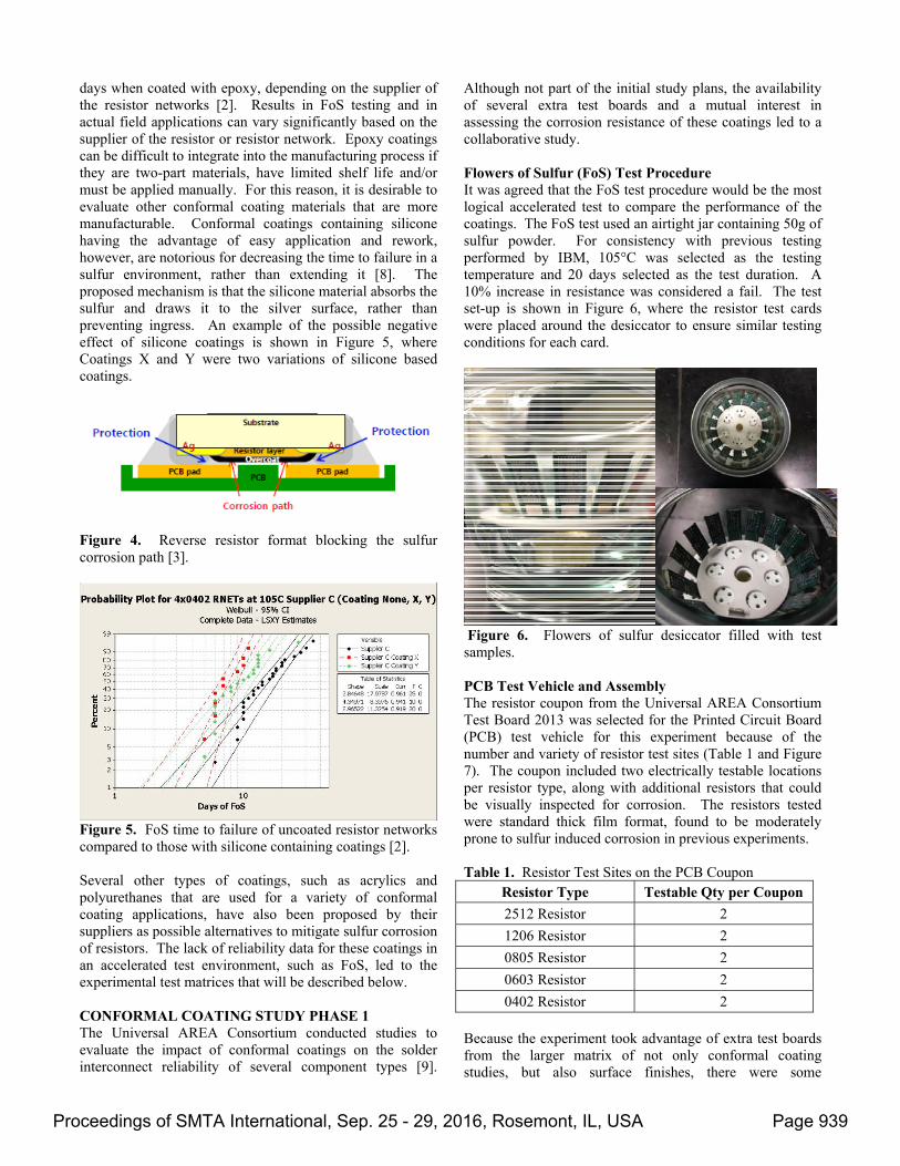
days when coated with epoxy, depending on the supplier of the resistor networks [2]. Results in FoS testing and in actual field applications can vary significantly based on the supplier of the resistor or resistor network. Epoxy coatings can be difficult to integrate into the manufacturing process if they are two-part materials, have limited shelf life and/or must be applied manually. For this reason, it is desirable to evaluate other conformal coating materials that are more manufacturable. Conformal coatings containing silicone having the advantage of easy application and rework, however, are notorious for decreasing the time to failure in a sulfur environment, rather than extending it [8]. The proposed mechanism is that the silicone material absorbs the sulfur and draws it to the silver surface, rather than preventing ingress. An example of the possible negative effect of silicone coatings is shown in Figure 5, where Coatings X and Y were two variations of silicone based coatings.
Figure 4. Reverse resistor format blocking the sulfur corrosion path [3].
Figure 5. FoS time to failure of uncoated resistor networks compared to those with silicone containing coatings [2]. Several other types of coatings, such as acrylics and polyurethanes that are used for a variety of conformal coating applications, have also been proposed by their suppliers as possible alternatives to mitigate sulfur corrosion of resistors. The lack of reliability data for these coatings in an accelerated test environment, such as FoS, led to the experimental test matrices that will be described below. CONFORMAL COATING STUDY PHASE 1 The Universal AREA Consortium conducted studies to evaluate the impact of conformal coatings on the solder interconnect reliability of several component types [9].
Although not part of the initial study plans, the availability of several extra test boards and a mutual interest in assessing the corrosion resistance of these coatings led to a collaborative study. Flowers of Sulfur (FoS) Test Procedure It was agreed that the FoS test procedure would be the most logical accelerated test to compare the performance of the coatings. The FoS test used an airtight jar containing 50g of sulfur powder. For consistency with previous testing performed by IBM, 105°C was selected as the testing temperature and 20 days selected as the test duration. A 10% increase in resistance was considered a fail. The test set-up is shown in Figure 6, where the resistor test cards were placed around the desiccator to ensure similar testing conditions for each card.
Figure 6. Flowers of sulfur desiccator filled with test samples. PCB Test Vehicle and Assembly The resistor coupon from the Universal AREA Consortium Test Board 2013 was selected for the Printed Circuit Board (PCB) test vehicle for this experiment because of the number and variety of resistor test sites (Table 1 and Figure 7). The coupon included two electrically testable locations per resistor type, along with additional resistors that could be visually inspected for corrosion. The resistors tested were standard thick film format, found to be moderately prone to sulfur induced corrosion in previous experiments. Table 1. Resistor Test Sites on the PCB Coupon
Resistor Type Testable Qty per Coupon
2512 Resistor 2
1206 Resistor 2
0805 Resistor 2
0603 Resistor 2
0402 Resistor 2 Because the experiment took advantage of extra test boards from the larger matrix of not only conformal coating studies, but also surface finishes, there were some
Proceedings of SMTA International, Sep. 25 - 29, 2016, Rosemont, IL, USA Page 939

limitations in hardware availability. The conformal coating test coupons had an Organic Solderability Preservative (OSP) surface finish, while only Lead Free Hot Air Solder Leveling (LF HASL) and Electroless Nickel Immersion Gold (ENIG) surface finish cards were available to use as non-coated controls. Since the purpose of the FoS testing was to evaluate the resistors rather than the PCB metallization, the surface finish was not deemed a critical factor. All of the resistor assembly was performed in the Universal Advanced Process Lab using Sn/Ag/Cu no-clean paste. The other conformal coating studies included coating thickness and flux cleaning as variables, so the FoS test matrix included a limited comparison of these variables as well.
Figure 7. Test Board 2013 (Top) and the resistor coupon (Bottom). Conformal Coatings and Experimental Matrix Three different conformal coating materials were evaluated.
Polyurethane 1 (PU1) A two-component urethane system designed for insulating printed circuit board assemblies; exhibits low outgassing in the cured state.
Polyurethane 2 (PU2) A single component polyurethane material formulated for use in automated spray equipment.
Acrylic 1 (A1) A fast drying, single component, acrylic formulated for use in automated spray equipment.
The details of the coating operations can be found in the reference paper [9]. The experimental matrix for the Phase 1 resistor corrosion study is shown in Table 2. Table 2. Phase 1 Experimental Matrix Build Lot
Qty PCB
Finish Conformal
Coating Thick*
Board Clean
CC1 4 OSP PU1 25 Yes CC2 4 OSP PU1 75 Yes CC3 4 OSP PU2 25 Yes CC4 4 OSP PU2 75 Yes CC5 4 OSP A1 75 Yes CC6 4 OSP A1 75 No
Control 1
3 LF
HASL none NA Yes
Control 2
1 ENIG none NA No
*Nominal target thickness Phase 1 Results The results of the 20 days of FoS testing were mixed. The data can be examined for trends, but are not conclusive because the controls did not fail as quickly as expected in many cases. The following trends were observed:
Uncoated resistors on LF HASL (Control 1) had failures within 20 days, although 100% did not fail in all body sizes
Uncoated resistors on ENIG (Control 2) did not fail within 20 days
PU1 coated resistors had similar percentage failure in both thickness cells and typically were equal to or better than uncoated resistors on LF HASL
A1 coated resistors with cleaning had somewhat worse performance than the PU1 coated resistors
A1 coated resistors without cleaning had somewhat better performance than the PU1 coated resistors and the A1 coated resistors with cleaning
PU2 coated resistors in both coating thicknesses did not fail within 20 days
The complete results are shown in Figure 8. Photographs of the coated coupons after 20 days of testing are shown in Figure 9.
Proceedings of SMTA International, Sep. 25 - 29, 2016, Rosemont, IL, USA Page 940
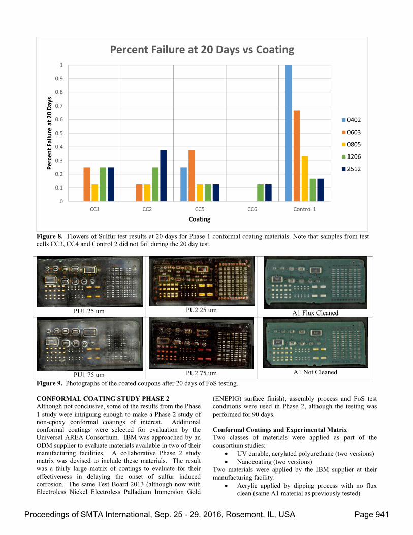
Figure 8. Flowers of Sulfur test results at 20 days for Phase 1 conformal coating materials. Note that samples from test cells CC3, CC4 and Control 2 did not fail during the 20 day test.
PU1 25 um PU2 25 um
A1 Flux Cleaned
PU1 75 um
PU2 75 um
A1 Not Cleaned
Figure 9. Photographs of the coated coupons after 20 days of FoS testing. CONFORMAL COATING STUDY PHASE 2 Although not conclusive, some of the results from the Phase 1 study were intriguing enough to make a Phase 2 study of non-epoxy conformal coatings of interest. Additional conformal coatings were selected for evaluation by the Universal AREA Consortium. IBM was approached by an ODM supplier to evaluate materials available in two of their manufacturing facilities. A collaborative Phase 2 study matrix was devised to include these materials. The result was a fairly large matrix of coatings to evaluate for their effectiveness in delaying the onset of sulfur induced corrosion. The same Test Board 2013 (although now with Electroless Nickel Electroless Palladium Immersion Gold
(ENEPIG) surface finish), assembly process and FoS test conditions were used in Phase 2, although the testing was performed for 90 days. Conformal Coatings and Experimental Matrix Two classes of materials were applied as part of the consortium studies:
UV curable, acrylated polyurethane (two versions) Nanocoating (two versions)
Two materials were applied by the IBM supplier at their manufacturing facility:
Acrylic applied by dipping process with no flux clean (same A1 material as previously tested)
0
0.1
0.2
0.3
0.4
0.5
0.6
0.7
0.8
0.9
1
CC1 CC2 CC5 CC6 Control 1
Percent Failu
re at 20 Days
Coating
Percent Failure at 20 Days vs Coating
0402
0603
0805
1206
2512
Proceedings of SMTA International, Sep. 25 - 29, 2016, Rosemont, IL, USA Page 941

Polyurethane with no flux clean The control cells were expanded beyond the uncoated coupons to include “known good” and “known bad” coatings applied by hand in the IBM lab:
Silicone Epoxy
The experimental matrix for the Phase 2 resistor corrosion study is shown in Table 3. Table 3. Phase 2 Experimental Matrix
Build Lot
Qty Conformal
Coating Process Info
CC7 2 APU1 Applied to coupon
by 3rd party
CC8 2 APU2 Applied to entire card by supplier
CC9 2 Nano1 Applied by
supplier
CC10 2 Nano2 Applied by
supplier CC11 2 A1 Applied by ODM CC12 2 PU3 Applied by ODM
Control 3 1 Uncoated Applied by IBM Control 4 1 Silicone Applied by IBM Control 5 1 Epoxy NA Phase 2 Results
The results of the 90 day FoS test again were mixed. Figure 10 shows the days to earliest failure and Figure 11 shows the average days to failure. The controls performed as expected. The silicone-based coating accelerated the first failure and average time to failure across all of the body sizes. The epoxy coating was nearly invincible with one fail occurring at 70 days on an 0402 resistor. There were some body size trends similar to those observed in previous testing. The 0402 was typically the worst performer. There was a trend of increasing time to failure with increasing body size. This observation was true especially for first failure. There were several cases, however, that did not follow the trend. The performance of the various coatings being studied was inconsistent. The acrylated polyurethanes provided some improvement, with APU1 outperforming APU2:
APU1 effective on high risk 0402 APU1 somewhat better than APU2, especially on
average APU2 had 0402 early failure
Note that resistors that did not fail are shown as 91 days Figure 10. Days to earliest failure versus coating.
0
10
20
30
40
50
60
70
80
90
Control 3 Control 4 Control 5 APU1 APU2 A1 PU3 Nano 1 Nano 2
Days to Earlie
st Failure
Coating
Days to Earliest Failure vs Coating
0402
0603
0805
1206
2512
Proceedings of SMTA International, Sep. 25 - 29, 2016, Rosemont, IL, USA Page 942
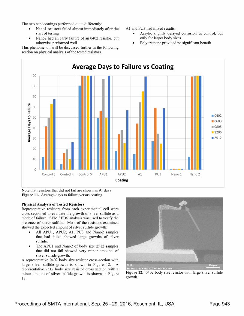
The two nanocoatings performed quite differently: Nano1 resistors failed almost immediately after the
start of testing Nano2 had an early failure of an 0402 resistor, but
otherwise performed well This phenomenon will be discussed further in the following section on physical analysis of the tested resistors.
A1 and PU3 had mixed results:
Acrylic slightly delayed corrosion vs control, but only for larger body sizes
Polyurethane provided no significant benefit
Physical Analysis of Tested Resistors Representative resistors from each experimental cell were cross sectioned to evaluate the growth of silver sulfide as a mode of failure. SEM / EDS analysis was used to verify the presence of silver sulfide. Most of the resistors examined showed the expected amount of silver sulfide growth:
All APU1, APU2, A1, PU3 and Nano2 samples that had failed showed large growths of silver sulfide.
The APU1 and Nano2 of body size 2512 samples that did not fail showed very minor amounts of silver sulfide growth.
A representative 0402 body size resistor cross-section with large silver sulfide growth is shown in Figure 12. A representative 2512 body size resistor cross section with a minor amount of silver sulfide growth is shown in Figure 13.
Figure 12. 0402 body size resistor with large silver sulfide growth.
Note that resistors that did not fail are shown as 91 days Figure 11. Average days to failure versus coating.
0
10
20
30
40
50
60
70
80
90
Control 3 Control 4 Control 5 APU1 APU2 A1 PU3 Nano 1 Nano 2
Average
Days to Failure
Coating
Average Days to Failure vs Coating
0402
0603
0805
1206
2512
Proceedings of SMTA International, Sep. 25 - 29, 2016, Rosemont, IL, USA Page 943
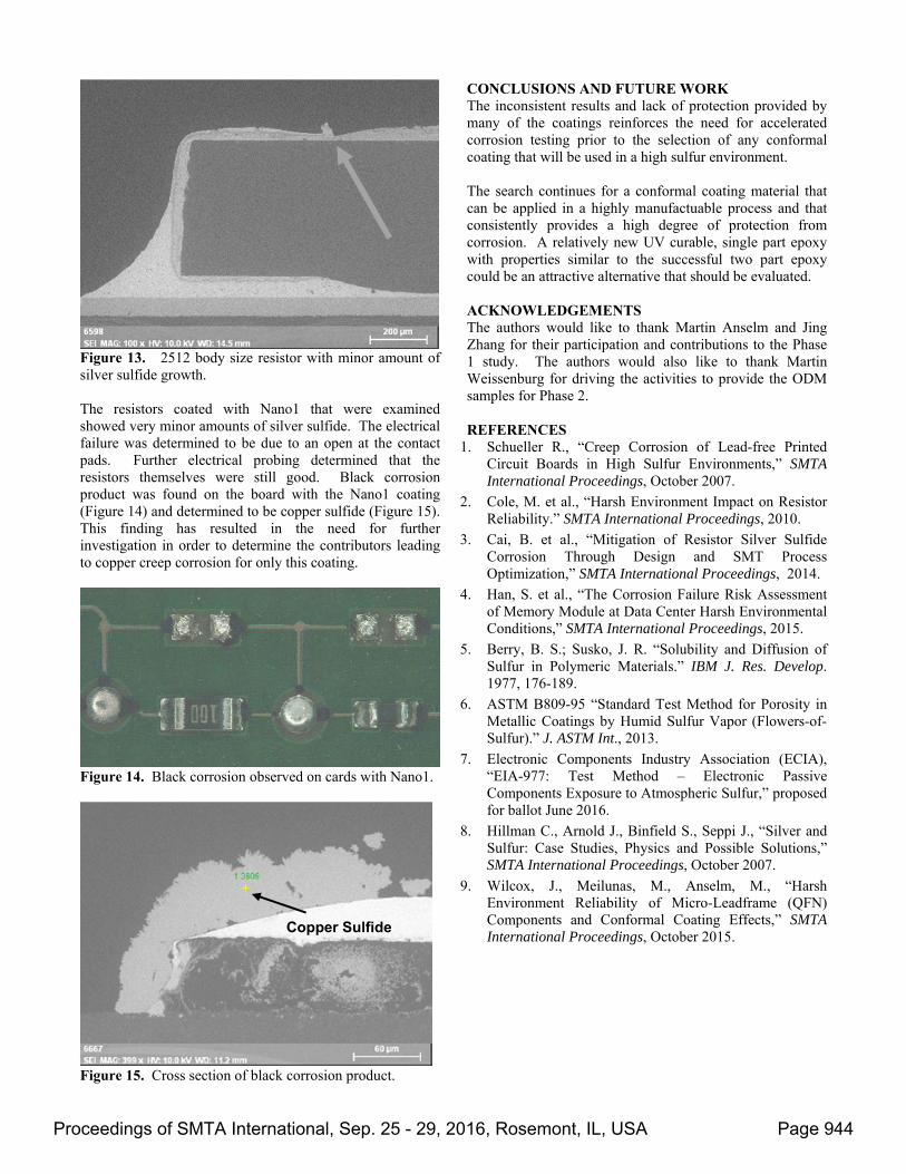
Figure 13. 2512 body size resistor with minor amount of silver sulfide growth. The resistors coated with Nano1 that were examined showed very minor amounts of silver sulfide. The electrical failure was determined to be due to an open at the contact pads. Further electrical probing determined that the resistors themselves were still good. Black corrosion product was found on the board with the Nano1 coating (Figure 14) and determined to be copper sulfide (Figure 15). This finding has resulted in the need for further investigation in order to determine the contributors leading to copper creep corrosion for only this coating.
Figure 14. Black corrosion observed on cards with Nano1.
Figure 15. Cross section of black corrosion product.
CONCLUSIONS AND FUTURE WORK The inconsistent results and lack of protection provided by many of the coatings reinforces the need for accelerated corrosion testing prior to the selection of any conformal coating that will be used in a high sulfur environment. The search continues for a conformal coating material that can be applied in a highly manufactuable process and that consistently provides a high degree of protection from corrosion. A relatively new UV curable, single part epoxy with properties similar to the successful two part epoxy could be an attractive alternative that should be evaluated. ACKNOWLEDGEMENTS The authors would like to thank Martin Anselm and Jing Zhang for their participation and contributions to the Phase 1 study. The authors would also like to thank Martin Weissenburg for driving the activities to provide the ODM samples for Phase 2. REFERENCES
1. Schueller R., “Creep Corrosion of Lead-free Printed Circuit Boards in High Sulfur Environments,” SMTA International Proceedings, October 2007.
2. Cole, M. et al., “Harsh Environment Impact on Resistor Reliability.” SMTA International Proceedings, 2010.
3. Cai, B. et al., “Mitigation of Resistor Silver Sulfide Corrosion Through Design and SMT Process Optimization,” SMTA International Proceedings, 2014.
4. Han, S. et al., “The Corrosion Failure Risk Assessment of Memory Module at Data Center Harsh Environmental Conditions,” SMTA International Proceedings, 2015.
5. Berry, B. S.; Susko, J. R. “Solubility and Diffusion of Sulfur in Polymeric Materials.” IBM J. Res. Develop. 1977, 176-189.
6. ASTM B809-95 “Standard Test Method for Porosity in Metallic Coatings by Humid Sulfur Vapor (Flowers-of-Sulfur).” J. ASTM Int., 2013.
7. Electronic Components Industry Association (ECIA), “EIA-977: Test Method – Electronic Passive Components Exposure to Atmospheric Sulfur,” proposed for ballot June 2016.
8. Hillman C., Arnold J., Binfield S., Seppi J., “Silver and Sulfur: Case Studies, Physics and Possible Solutions,” SMTA International Proceedings, October 2007.
9. Wilcox, J., Meilunas, M., Anselm, M., “Harsh Environment Reliability of Micro-Leadframe (QFN) Components and Conformal Coating Effects,” SMTA International Proceedings, October 2015.
Copper Sulfide
Proceedings of SMTA International, Sep. 25 - 29, 2016, Rosemont, IL, USA Page 944