EFDA 10 th Meeting of the ITPA Topical Group on Diagnostics 10-14 April, 2006, Moscow, Russia...
28
EFDA 10 th Meeting of the ITPA Topical Group on Diagnostics 10-14 April, 2006, Moscow, Russia Progress on the design of various magnetic sensors for ITER: diamagnetic and flux loops, high- frequency coils, in-vessel and divertor coils, ex-vessel coils, and external Rogowskis Anna Encheva for the CRPP team Ecole Polytechnique Fédérale de Lausanne (EPFL) Centre de Recherches en Physique des Plasmas Association Euratom- Confédération Suisse CH-1015 Lausanne Switzerland
-
Upload
percival-simpson -
Category
Documents
-
view
215 -
download
1
Transcript of EFDA 10 th Meeting of the ITPA Topical Group on Diagnostics 10-14 April, 2006, Moscow, Russia...

EFDA
10th Meeting of the ITPA Topical Group on Diagnostics 10-14 April, 2006, Moscow, Russia
Progress on the design of various magnetic sensors for ITER:
diamagnetic and flux loops, high-frequency coils, in-vessel and divertor coils, ex-vessel
coils, and external Rogowskis
Anna Encheva
for the CRPP team Ecole Polytechnique Fédérale de Lausanne (EPFL) Centre de Recherches en Physique des Plasmas
Association Euratom-Confédération Suisse CH-1015 Lausanne Switzerland

10th Meeting of the ITPA Topical Group on Diagnostics 10-14 April, 2006, Moscow, Russia
AssociationEuratom
Slide 2
Outline
ITER Measurement requirements
Location within or outside the vessel
Design features
Open design issues
Research activities withing EFDA TWP 2005
High frequency coils
MHD Saddle loops
Diamagnetic loops
Divertor coils
Ex-vessel coils
Ex-vessel Rogowskis
In-vessel flux loops
Anna Encheva

10th Meeting of the ITPA Topical Group on Diagnostics 10-14 April, 2006, Moscow, Russia
AssociationEuratomMeasurement requirements
Measurement Parameter Condition Range ΔT or ΔF
ΔX or Δk Accuracy (2σ)
Plasma current Ip Default 0-1 MA 1 ms Integral 10 kA
1-17.5 MA 1 ms Integral 1 %
Ip Quench 17.5-0 MA 0.1 ms Integral 30% +10 kA
Plasma position and
shape
Main plasma gaps, Δsep
Ip>2 MA, full bore
- 10 ms - 1 cm
Ip Quench - 10 ms - 2 cm
Divertor channel location
Default - 10 ms - 1 cm
Ip Quench - 10 ms - 2 cm
dZ/dT of current centroid
Default 0-5 m/s 1 ms - 0.05 m/s (noise) + 2 % (error)
Low (m,n) MHD modes,
Sawteeth, Disruption precursors
Mode complex
amplitude at wall
TBD DC – 3 kHz
(0,0)<(m,n)< (10,2)
10%
High frequency macro
instabilities (Fishbones,
TAEs)
Fishbone-induced
perturbations in B,T,n
TBD 0.1-10 kHz
(m,n)=(1,1) -
TAE mode-induced
perturbations in B,T,n
TBD 30-300 kHz
n=10 - 50 -
Main system:
Low (m,n) MHD modes, sawteeth, disruption precursors
High frequency macro instabilities
Backups:
Plasma current
Plasma position and shape
Slide 3
HF coils
Anna Encheva
10th Meeting of the ITPA Topical Group on Diagnostics 10-14 April, 2006, Moscow, Russia
AssociationEuratom
Slide 4
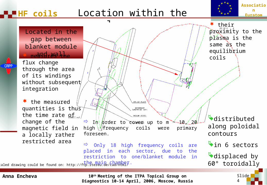
HF coils Location within the vessel
Located in the gap between blanket module and wall
distributed along poloidal contours
in 6 sectors
displaced by 60° toroidally
* The scaled drawing could be found on: http://ftp.itereu.de/cad/html/
In order to cover up to m ~ 10, 20 high frequency coils were primary foreseen.
Only 18 high frequency coils are placed in each sector, due to the restriction to one/blanket module in the main chamber.
their proximity to the plasma is the same as the equilibrium coils
measures the flux change through the area of its windings without subsequent integration
the measured quantities is thus the time rate of change of the magnetic field in a locally rather restricted area
Anna Encheva

10th Meeting of the ITPA Topical Group on Diagnostics 10-14 April, 2006, Moscow, Russia
AssociationEuratom
HF coils
Slide 5
Present design features
for avoid short-circuiting between the two layers of windings - ceramic is grooved with one layer of deep and one layer of shallow grooves which cross each other
for high bandwidth a wide gap is constructed
coil supports are insulated to reduce eddy currents
for reducing the internal coil capacitance – larger winding pitch for minimizing stray fields and avoiding noise in the signal - even number of layers and windings is necessary
for getting a high induced voltage signal – effective area of the coil has to be large
Anna Encheva

10th Meeting of the ITPA Topical Group on Diagnostics 10-14 April, 2006, Moscow, Russia
AssociationEuratom
HF coils
Slide 6
Present design features
usable at up to 2 MHz measure both: equilibrium field andfluctuation related to plasma instabilities
heat shield – protection from the plasma, prevent from interfering with
other circuitsShield - connected to the vessel ground the coils has to be fully isolated from the casing
bobbin - made of stainless steel layer and copper strips
proposed implementation (minimum physics):
one poloidal array of ~20 coils (with non-uniform distribution) covering both low- and the high-field side on 3 machine sectors for redundancy, each coil with effective area (NA)EFF=0.1m2
two toroidal arrays of 20 coils (with non-uniform distribution) located at Z=ZMAG30cm, each coil with effective area (NA)EFF=0.1m2
Anna Encheva
10th Meeting of the ITPA Topical Group on Diagnostics 10-14 April, 2006, Moscow, Russia
AssociationEuratom
HF coils
Slide 7
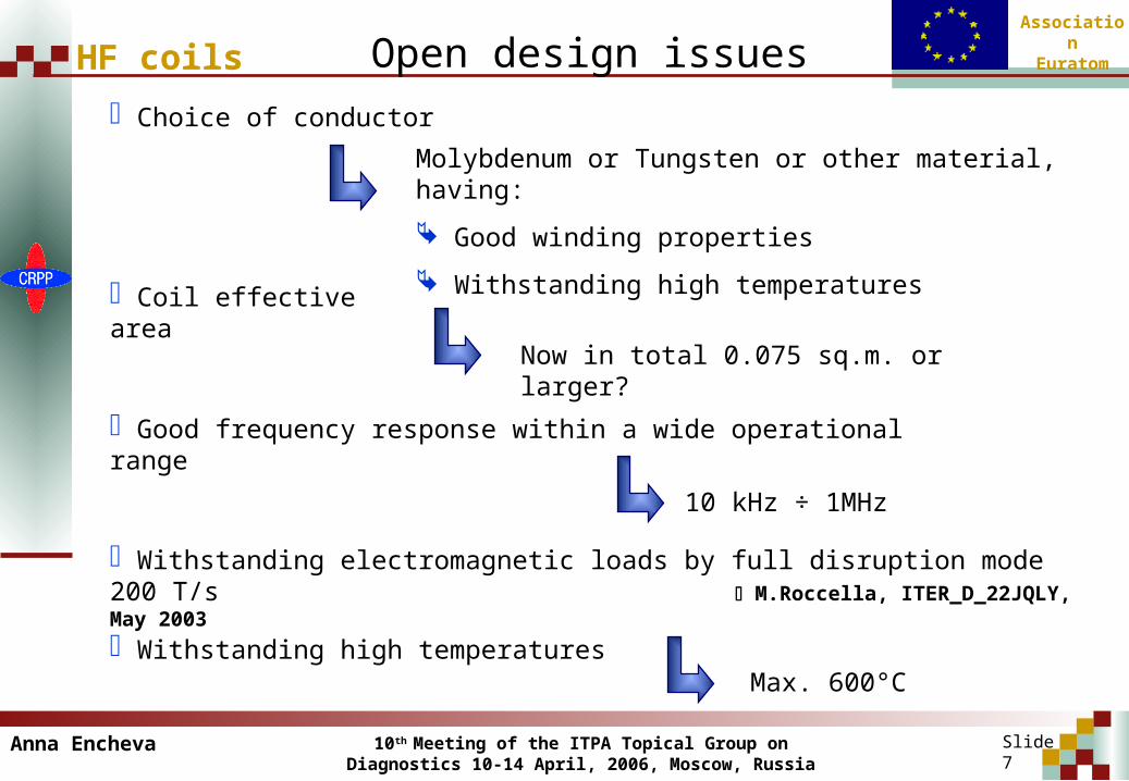
Open design issues Choice of conductor
Molybdenum or Tungsten or other material, having:
Good winding properties
Withstanding high temperatures
Coil effective area
Now in total 0.075 sq.m. or larger?
Good frequency response within a wide operational range
Withstanding electromagnetic loads by full disruption mode 200 T/s M.Roccella, ITER_D_22JQLY, May 2003
10 kHz ÷ 1MHz
Withstanding high temperatures Max. 600°C
Anna Encheva

10th Meeting of the ITPA Topical Group on Diagnostics 10-14 April, 2006, Moscow, Russia
AssociationEuratom
HF coils
Slide 8
Work plan 2006
Transient electromagnetic analysis:
full disruption mode : 200T/s induced voltage
Dynamic harmonic electromagnetic analysis:
induced eddy currents
amplitude - frequency response characteristics
Coupled field analysis:
Thermal analysis:
nuclear heating rate in the coil materials
temperature distribution in the coil structure
Structural analysis:
thermal loads
stress-strain distribution
Anna Encheva

10th Meeting of the ITPA Topical Group on Diagnostics 10-14 April, 2006, Moscow, Russia
AssociationEuratom
Measurement Parameter Condition Range ΔT or ΔF ΔX or Δk Accuracy (2σ)
Plasma position and shape
Main plasma gaps, Δsep
Ip > 2 MA, full bore
- 10 ms - 1 cm
Ip Quench - 10 ms - 2 cm
Divertor channel location
Default - 10 ms - 1 cm
Ip Quench - 10 ms - 2 cm
dZ/dT of current centroid
Default 0-5 m/s 1 ms - 0.05 m/s (noise) +
2 % (error)
Low (m,n) MHD modes,
Sawteeth, Disruption precursors
Mode complex
amplitude at wall
TBD DC – 3 kHz (0,0)<(m,n)< (10,2)
10%
Locked Modes Br(mode)/Bp 10-4 - 10-2 1 ms (m,n)=(2,1) 30%
Backups:
Plasma position and shape
Main system:
Locked modes
Low (m,n) MHD modes, sawteeth, disruption precursors
If necessary: MHD saddles as backup measurements for the equilibrium reconstruction
Slide 9
Measurement requirementsMHD saddles
Anna Encheva

10th Meeting of the ITPA Topical Group on Diagnostics 10-14 April, 2006, Moscow, Russia
AssociationEuratomLocation within the vessel
Mounted on the inner wall of vacuum vessel Exist on 9 machine sector pairs
(40° apart toroidally)
Poloidally – 8 loops mounted on each sector
Saddle loops are permanent
Slide 10
MHD saddles
proposed implementation (general): toroidal distribution: 4 sets of ~15
saddle loops with non-uniform distribution at Z=ZMAG80cm
2 sets on low-field side + 2 sets on high-field side
toroidal positioning optimised for control of natural error field (TF ripple with/out ferrite inserts)
poloidal distribution: 1 set of ~20 saddle loops in >3 sectors
non-trivial role of *-correction (loops shrink: , lj)
redundancy is sufficient as saddle loops are permanent
where is ZMAG? need to optimise positioning of saddle loops as different magnetic equilibria are expected
effective area of each saddle loop (NA)EFF ~1.5m2
lower than previous DDD estimate (~5m2)
Anna Encheva

10th Meeting of the ITPA Topical Group on Diagnostics 10-14 April, 2006, Moscow, Russia
AssociationEuratomPresent design features
Loops of 2mm mineral insulated cable
attached to the vessel at frequent intervals via resistance-welded clips
Choice of MI cable Research activity, CIEMAT and SCK-
CEN
MHD saddles
Slide 11
Open design issues: design changes are required to satisfy full-scope physics requirements (∆ZMAG, *-
correction)
Anna Encheva
10th Meeting of the ITPA Topical Group on Diagnostics 10-14 April, 2006, Moscow, Russia
AssociationEuratom
Divertor coils
Slide 12
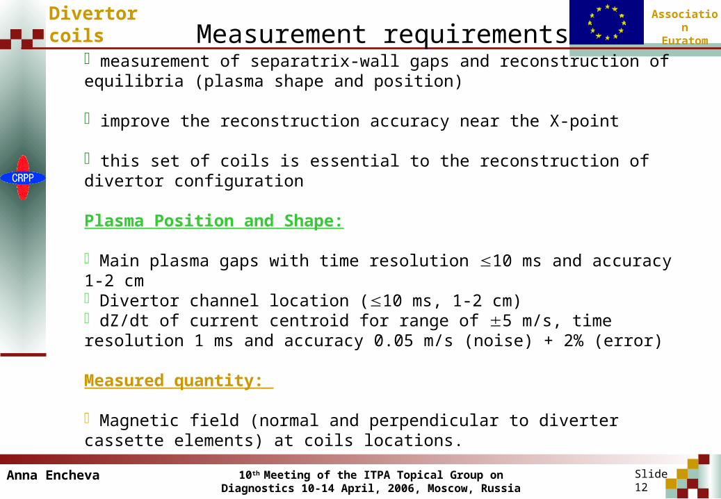
Measurement requirements
measurement of separatrix-wall gaps and reconstruction of equilibria (plasma shape and position)
improve the reconstruction accuracy near the X-point
this set of coils is essential to the reconstruction of divertor configuration
Plasma Position and Shape:
Main plasma gaps with time resolution 10 ms and accuracy 1-2 cm Divertor channel location (10 ms, 1-2 cm) dZ/dt of current centroid for range of 5 m/s, time resolution 1 ms and accuracy 0.05 m/s (noise) + 2% (error)
Measured quantity:
Magnetic field (normal and perpendicular to diverter cassette elements) at coils locations.
Anna Encheva

10th Meeting of the ITPA Topical Group on Diagnostics 10-14 April, 2006, Moscow, Russia
AssociationEuratom
Slide 13
Divertor coils Location within the vessel
* The scaled drawing could be found on: http://ftp.itereu.de/cad/html/
Position in the vessel: divertor cassette
Location: 72 (6x6x2) coils on 6 divertor cassettes
ports 02, 04, 08, 10, 14, 16 (6 position)
System: pairs of equilibrium coils normal and tangential to the mounting surfaces of selected cassettes
6 coils with an axis perpendicular to divertor cassette elements
6 separate coils at equivalent positions with an axis parallel to divertor cassette elements
Anna Encheva
10th Meeting of the ITPA Topical Group on Diagnostics 10-14 April, 2006, Moscow, Russia
AssociationEuratom
Slide 14
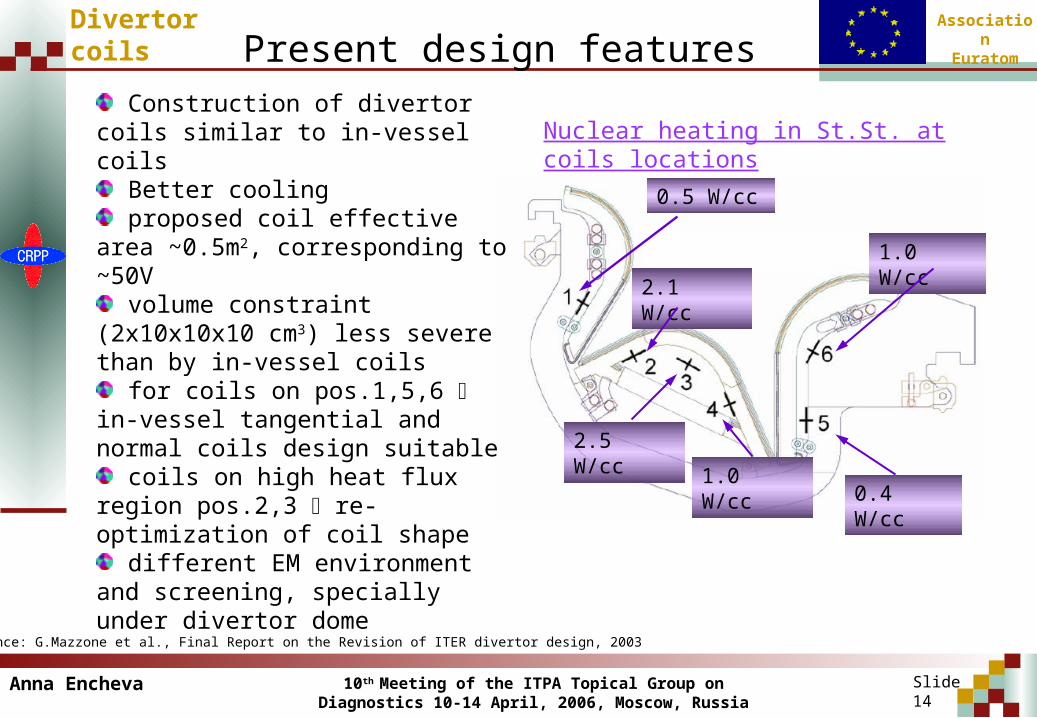
Divertor coils Present design features
* Reference: G.Mazzone et al., Final Report on the Revision of ITER divertor design, 2003
Nuclear heating in St.St. at coils locations
0.5 W/cc
2.1 W/cc
2.5 W/cc
1.0 W/cc0.4 W/cc
1.0 W/cc
Construction of divertor coils similar to in-vessel coils
Better cooling proposed coil effective area
~0.5m2, corresponding to ~50V volume constraint (2x10x10x10
cm3) less severe than by in-vessel coils
for coils on pos.1,5,6 in-vessel tangential and normal coils design suitable
coils on high heat flux region pos.2,3 re-optimization of coil shape
different EM environment and screening, specially under divertor dome
Anna Encheva
10th Meeting of the ITPA Topical Group on Diagnostics 10-14 April, 2006, Moscow, Russia
AssociationEuratom
Slide 15
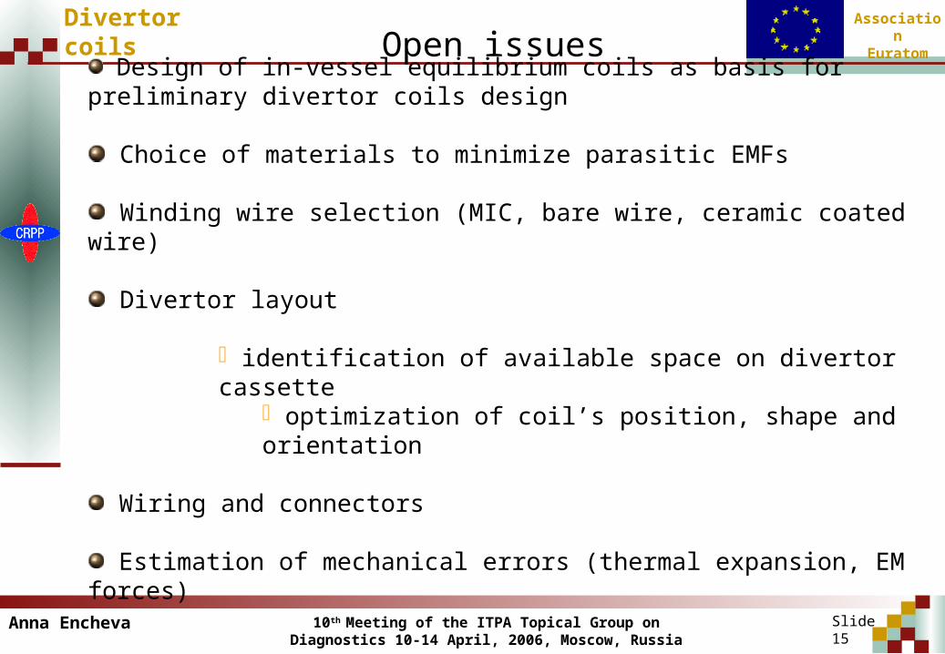
Divertor coils Open issues
Design of in-vessel equilibrium coils as basis for preliminary divertor coils design
Choice of materials to minimize parasitic EMFs
Winding wire selection (MIC, bare wire, ceramic coated wire)
Divertor layout
identification of available space on divertor cassette optimization of coil’s position, shape and orientation
Wiring and connectors
Estimation of mechanical errors (thermal expansion, EM forces)
Anna Encheva

10th Meeting of the ITPA Topical Group on Diagnostics 10-14 April, 2006, Moscow, Russia
AssociationEuratom
Divertor coils
Slide 16
Work plan 2006
Identification of available space on divertor cassette (A.Martin, ITER IT)
Re-design the present in-vessel coils for the position 2 and 3, under the divetor dome
Dynamic harmonic electromagnetic analysis
Thermal FE analysis
Anna Encheva
10th Meeting of the ITPA Topical Group on Diagnostics 10-14 April, 2006, Moscow, Russia
AssociationEuratom
Diamagnetic loop system
Slide 17
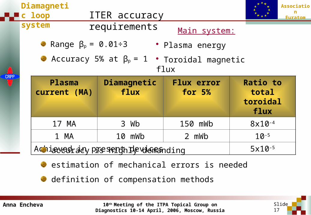
Range βp = 0.01÷3
Accuracy 5% at βp = 1
Plasma current (MA)
Diamagnetic flux
Flux error for 5%
Ratio to total toroidal flux
17 MA 3 Wb 150 mWb 8x10⁻⁴
1 MA 10 mWb 2 mWb 10-5
Achieved in present devices 5x10⁻⁵
accuracy is highly demanding
estimation of mechanical errors is needed
definition of compensation methods
ITER accuracy requirements
Anna Encheva
Main system:
Plasma energy
Toroidal magnetic flux
10th Meeting of the ITPA Topical Group on Diagnostics 10-14 April, 2006, Moscow, Russia
AssociationEuratom
Slide 18
Diamagnetic loop system
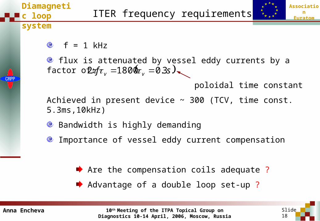
ITER frequency requirements
f = 1 kHz
flux is attenuated by vessel eddy currents by a factor of:
poloidal time constant
Achieved in present device ~ 300 (TCV, time const. 5.3ms,10kHz)
Bandwidth is highly demanding
Importance of vessel eddy current compensation
Are the compensation coils adequate ?
Advantage of a double loop set-up ?
.3.018002 sf vv
Anna Encheva

10th Meeting of the ITPA Topical Group on Diagnostics 10-14 April, 2006, Moscow, Russia
AssociationEuratom
Slide 19
Diamagnetic loop system
Location and design
3 sets mounted on the inner vessel wall, separated by 120°:
2 diamagnetic loop, wired in parallel (to circumvent obstacles)Attached to the wall by spot welded clips2 compensation coilsadditional poloidal field compensation loops
Obstacle
Diamagnetic loop contour
Compensation coil
Anna Encheva
10th Meeting of the ITPA Topical Group on Diagnostics 10-14 April, 2006, Moscow, Russia
AssociationEuratom
Slide 20
Diamagnetic loop system
Method for performance analysis
Identify and describe sources of mechanical errors (2005) construction misalignements and assembly errors in sensors
construction misalignements in PF and TF coils, VV
deformation under EM forces in PF and TF coils
deformation after thermal expansion of VV
Quantifying mechanical errors requires:
magnetic field mapping (2006)
thermal expansion modelling of VV (2006)
modelling of VV deformation under EM forces
modelling of eddy currents in VV (2006)
Anna Encheva

10th Meeting of the ITPA Topical Group on Diagnostics 10-14 April, 2006, Moscow, Russia
AssociationEuratom
Slide 21
Diamagnetic loop system
Diamagnetic loop status in short
Assessment of ITER measurement requirements:
very demanding
Methodology to perform comprehensive performance analysis
(requires modelling tool for various ITER components)
Feasibility of alternative set-up to be studied (double loop)
Anna Encheva
10th Meeting of the ITPA Topical Group on Diagnostics 10-14 April, 2006, Moscow, Russia
AssociationEuratom
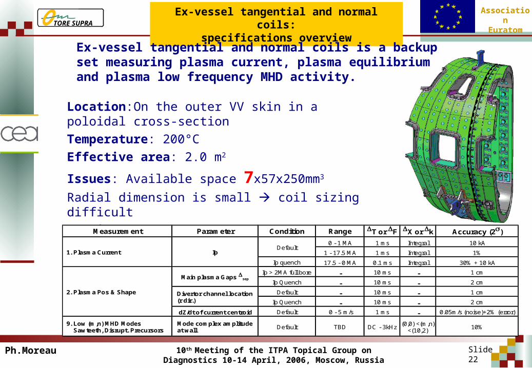
Ex-vessel tangential and normal coils:specifications overview
Ex-vessel tangential and normal coils is a backup set measuring plasma current, plasma equilibrium and plasma low frequency MHD activity.
Location: On the outer VV skin in a poloidal cross-sectionTemperature: 200°CEffective area: 2.0 m2
Issues: Available space 7x57x250mm3
Radial dimension is small coil sizing difficultRequirements:
Measurement Parameter Condition Range T or F X or k Accuracy (2)
1. Plasma Current Ip
2. Plasma Pos & Shape
9. Low (m,n) MHD Modes Sawteeth, Disrupt. Precursors
Default1 - 17.5 MA
0 - 1 MA
Ip quench 17.5 - 0 MA
1 ms
1 ms
0.1 ms
Integral
Integral
Integral
10 kA
1%
30% + 10 kA
Main plasma Gaps sep
Divertor channel location(r dir.)
Default
-
-
10 ms
10 ms
1 ms
-
-
-
1 cm
2 cm
0.05m/s (noise)+2% (error)
Ip Quench -
0 - 5 m/s
10 ms
Mode complex amplitudeat wall
-
2 cm
Ip > 2MA full bore
- 10 ms - 1 cmDefault
Ip Quench
dZ/dt of current centroid
Default TBD DC - 3kHz(0,0) <(m,n)
<(10,2)10%
Ph.Moreau Slide 22
TORE SUPRA
10th Meeting of the ITPA Topical Group on Diagnostics 10-14 April, 2006, Moscow, Russia
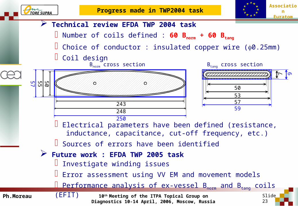
AssociationEuratomProgress made in TWP2004 task
Number of coils defined : 60 Bnorm + 60 Btang
Choice of conductor : insulated copper wire (0.25mm)
Coil design
Electrical parameters have been defined (resistance,inductance, capacitance, cut-off frequency, etc.)
Sources of errors have been identified
243248250
57
55
50
7 9
50535759
Bnorm cross section Btang cross section
Investigate winding issues
Error assessment using VV EM and movement models
Performance analysis of ex-vessel Bnorm and Btang coils (EFIT)
Technical review EFDA TWP 2004 task
Future work : EFDA TWP 2005 task
Ph.Moreau Slide 23
TORE SUPRA

10th Meeting of the ITPA Topical Group on Diagnostics 10-14 April, 2006, Moscow, Russia
AssociationEuratom
Ex-vessel continuous Rogowski:specifications overview
Ex-Vessel continuous Rogowski is a separate backup measuring the plasma current and giving relevant information on current flowing through the vessel.
Location: In 14.5mm diameter groove cut inTFC casing, coil OD is 12mm
Temperature: 4.0K
Sensitivity: typ. 800 mV s / MA
Issues: Available space, joints
Requirements :
Measurement Parameter Condition Range T or F X or k Accuracy (2)
1. Plasma Current Ip
2. Plasma Pos & Shape
Default1 - 17.5 MA
0 - 1 MA
Ip quench 17.5 - 0 MA
1 ms
1 ms
0.1 ms
Integral
Integral
Integral
10 kA
1%
30% + 10 kA
Main plasma Gaps sep
Divertor channel location(r dir.)
Default
-
-
10 ms
10 ms
1 ms
-
-
-
1 cm
2 cm
0.05m/s (noise)+2% (error)
Ip Quench -
0 - 5 m/s
10 ms -
2 cm
Ip > 2MA full bore
- 10 ms - 1 cmDefault
Ip Quench
dZ/dt of current centroid
Ph.Moreau Slide 24
TORE SUPRA
10th Meeting of the ITPA Topical Group on Diagnostics 10-14 April, 2006, Moscow, Russia
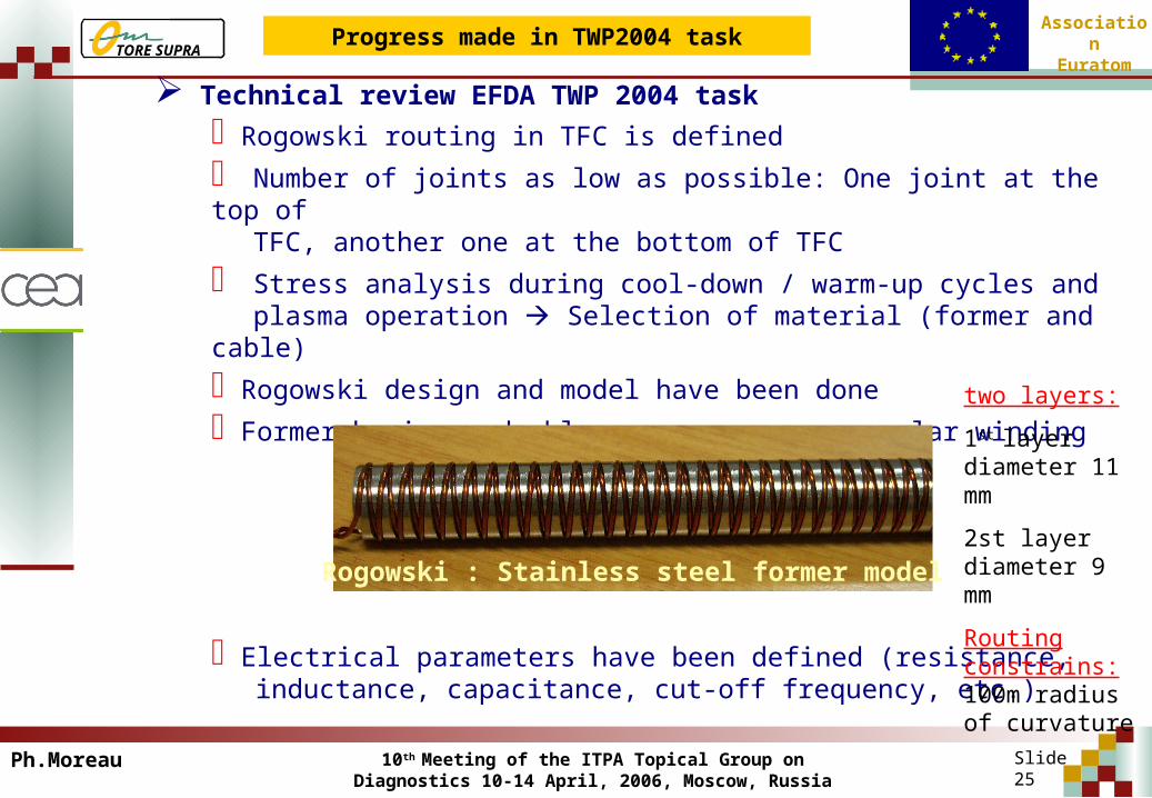
AssociationEuratomProgress made in TWP2004 task
Rogowski routing in TFC is defined
Number of joints as low as possible: One joint at the top ofTFC, another one at the bottom of TFC
Stress analysis during cool-down / warm-up cycles andplasma operation Selection of material (former and cable)
Rogowski design and model have been done
Former having a double screw groove – regular winding
Electrical parameters have been defined (resistance,inductance, capacitance, cut-off frequency, etc.)
Technical review EFDA TWP 2004 task
Rogowski : Stainless steel former model
two layers:
1st layer diameter 11 mm
2st layer diameter 9 mm
Routing constrains: 100m radius of curvature
Ph.Moreau Slide 25
TORE SUPRA

10th Meeting of the ITPA Topical Group on Diagnostics 10-14 April, 2006, Moscow, Russia
AssociationEuratomTORE SUPRA
Slide 26
Refine the design and former selection (easy bending)
Rogowskis in two parts
Define the joints
Assess Rogowski’s accuracy and source of error
Future work : EFDA TWP 2005 task
Ex-vessel continuous Rogowski:specifications overview
Ph.Moreau
10th Meeting of the ITPA Topical Group on Diagnostics 10-14 April, 2006, Moscow, Russia
AssociationEuratom
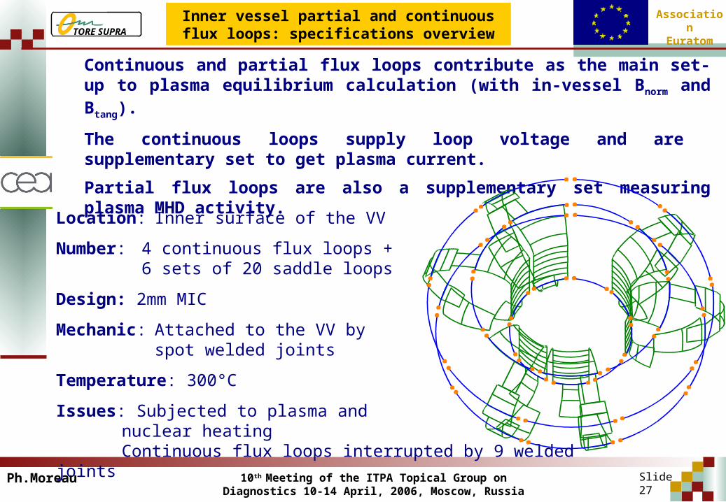
Inner vessel partial and continuous flux loops: specifications overview
Continuous and partial flux loops contribute as the main set-up to plasma equilibrium calculation (with in-vessel Bnorm and Btang).
The continuous loops supply loop voltage and are supplementary set to get plasma current.
Partial flux loops are also a supplementary set measuring plasma MHD activity.
Location: Inner surface of the VV
Number: 4 continuous flux loops + 6 sets of 20 saddle loops
Design: 2mm MIC
Mechanic: Attached to the VV byspot welded joints
Temperature: 300°C
Issues: Subjected to plasma and nuclear heatingContinuous flux loops interrupted by 9 welded joints
Ph.Moreau Slide 27
TORE SUPRA

10th Meeting of the ITPA Topical Group on Diagnostics 10-14 April, 2006, Moscow, Russia
AssociationEuratom
Section for removal
Contact plate
Flux loop
Connection
Support plate
Joint soldered tosupport plate
Progress made in TWP2004 task
9 special welded joints allowing 3 replacements by remote handling
Electrical parameters have been defined (resistance,inductance, capacitance, cut-off frequency, etc.)
Source of errors have been investigated
Define the thermal gradient along the cable (TIEMF effect)
Measurement errors assessment using VV EM and movement models
Technical review EFDA TWP 2004 task
Open issues
Ph.Moreau Slide 28
TORE SUPRA