EEL5225: Principles of MEMS Transducers (Fall 2003 ... EEL5225: Principles of MEMS Transducers (Fall...
17
EEL5225: Principles of MEMS Transducers (Fall 2003) 1 EEL5225: Principles of MEMS Transducers (Fall 2003) Instructor: Dr. Hui-Kai Xie Lumped-Element Modeling Last lecture Two-port element example: inductor Transducers – Classification – Linear, Conservative – General Two-Port Theory Today: Review of Electromagnetics Electrodynamic transduction Lecture 19 by H.K. Xie 10/10/2003
Transcript of EEL5225: Principles of MEMS Transducers (Fall 2003 ... EEL5225: Principles of MEMS Transducers (Fall...
EEL5225: Principles of MEMS Transducers (Fall 2003)1
EEL5225: Principles of MEMS Transducers (Fall 2003)Instructor: Dr. Hui-Kai Xie
Lumped-Element ModelingLast lecture
Two-port element example: inductorTransducers
– Classification– Linear, Conservative– General Two-Port Theory
Today:Review of ElectromagneticsElectrodynamic transduction
Lecture 19 by H.K. Xie 10/10/2003
EEL5225: Principles of MEMS Transducers (Fall 2003)2
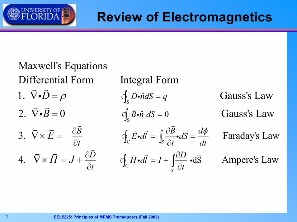
Review of Electromagnetics
S
ˆ
ˆ 0
Maxwell's EquationsDifferential Form Integral Form1. Gauss's Law
2. 0 SD ndS q
B n dS
D
B
ρ =
=
∇ =
∇ =∫ i
i
i
i
C
C
dS
Faraday's Law
4. Ampere's Law
Gauss's Law
3.
S
S
B B dE dl dSt t dtD DH dl It t
E
H J
φ∂ ∂= =
∂ ∂∂ ∂
= +∂ ∂
∇× = − −
∇× = +
∫
∫ ∫
∫ ∫
i i
i i
EEL5225: Principles of MEMS Transducers (Fall 2003)3
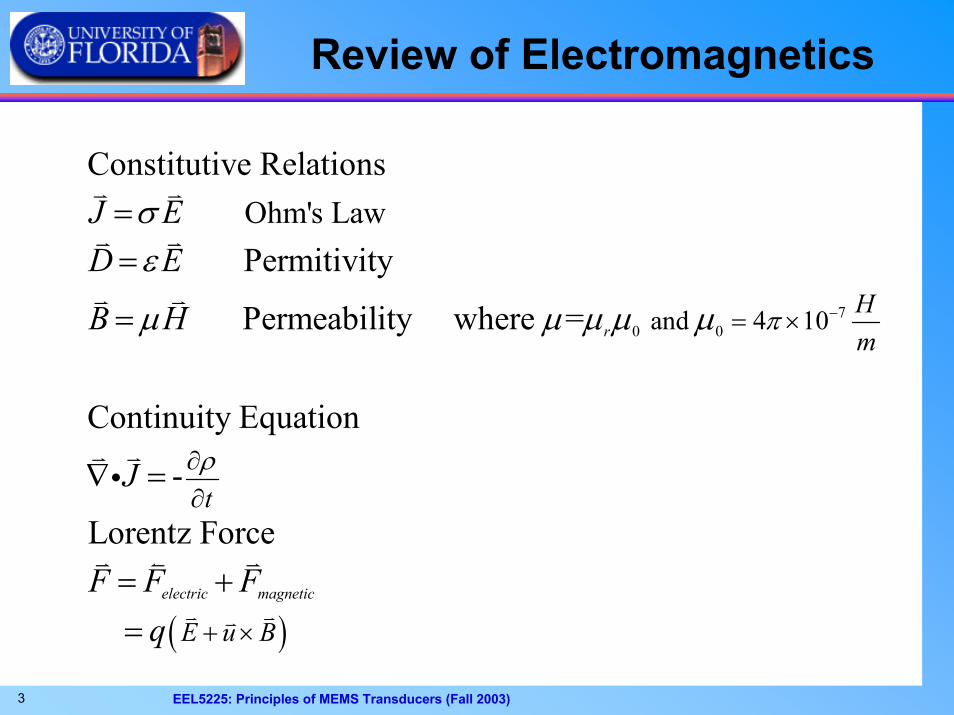
Review of Electromagnetics
70 0
and 4 10
Ohm's Law
Constitutive Relations
Permitivity
Permeability where =
Continuity Equation
rHm
J ED E
B H π
σε
µ µ µ µ µ −= ×
==
=
( )
-
Lorentz Force
electric magnetic
t
E u B
J
F F Fq
ρ∂∂
+ ×
∇ =
= +=
i
EEL5225: Principles of MEMS Transducers (Fall 2003)4
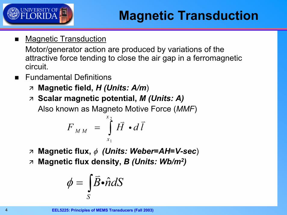
Magnetic TransductionMagnetic TransductionMotor/generator action are produced by variations of the attractive force tending to close the air gap in a ferromagneticcircuit.Fundamental Definitions
Magnetic field, H (Units: A/m)Scalar magnetic potential, M (Units: A)Also known as Magneto Motive Force (MMF)
Magnetic flux, φ (Units: Weber=AH=V-sec)Magnetic flux density, B (Units: Wb/m2)
2
1
x
M Mx
F H d l= ∫ i
ˆS
B ndSφ = ∫ i
EEL5225: Principles of MEMS Transducers (Fall 2003)5
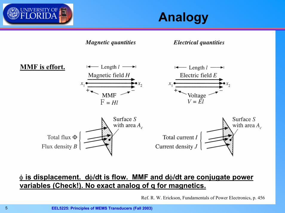
Analogy
MMF is effort.
φ is displacement. dφ/dt is flow. MMF and dφ/dt are conjugate power variables (Check!). No exact analog of q for magnetics.
Ref. R. W. Erickson, Fundamentals of Power Electronics, p. 456
EEL5225: Principles of MEMS Transducers (Fall 2003)6
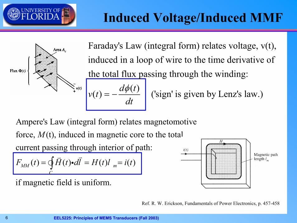
Induced Voltage/Induced MMF
Faraday's Law (integral form) relates voltage, v(t), induced in a loop of wire to the time derivative of the total flux passing through the winding:
( )( ) ('sign' is given by Lenz's law.)d tv tdtφ
= −
Ampere's Law (integral form) relates magnetomotiveforce, (t), induced in magnetic core to the totalcurrent passing through interior of path:
( ) ( ) ( ) ( )
if magnetic field is uniform
MM mC
M
F t H t dl H t l i t= = =∫ i
.
Ref. R. W. Erickson, Fundamentals of Power Electronics, p. 457-458
EEL5225: Principles of MEMS Transducers (Fall 2003)7
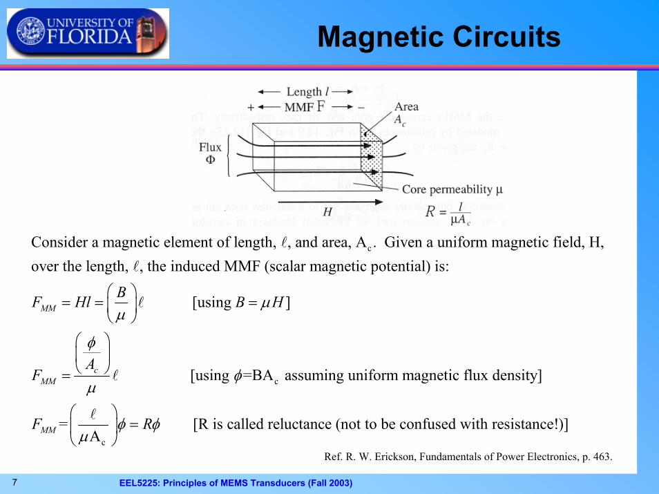
Magnetic Circuits
Ref. R. W. Erickson, Fundamentals of Power Electronics, p. 463.
cConsider a magnetic element of length, , and area, A . Given a uniform magnetic field, H,over the length, , the induced MMF (scalar magnetic potential) is:
[using ]MM
M
BF Hl B H
F
µµ
= = =
c
c
[using =BA assuming uniform magnetic flux density]
= [R is called reluctance (not to be confused with resistance!)]A
cM
MM
A
F R
φ
φµ
φ φµ
=
=
EEL5225: Principles of MEMS Transducers (Fall 2003)8
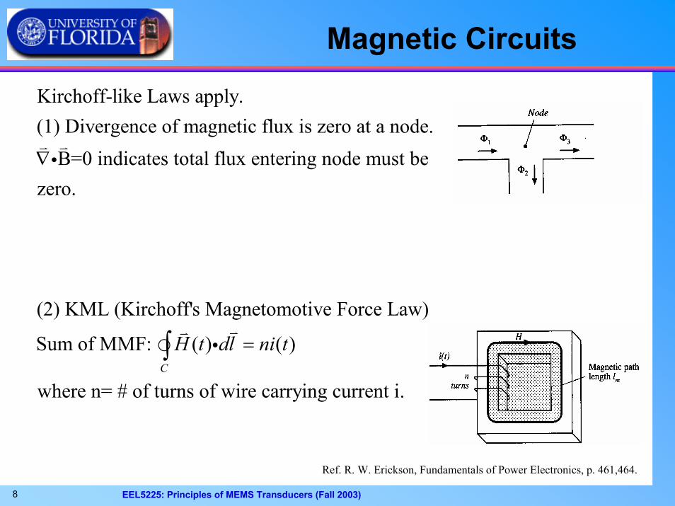
Magnetic Circuits
Kirchoff-like Laws apply.(1) Divergence of magnetic flux is zero at a node.
B=0 indicates total flux entering node must bezero.
(2) KML (Kirchoff's Magnetomotive Force Law)
Sum of MMF: ( ) (H t dl ni t
∇
=
i
i )
where n= # of turns of wire carrying current i.C∫
Ref. R. W. Erickson, Fundamentals of Power Electronics, p. 461,464.
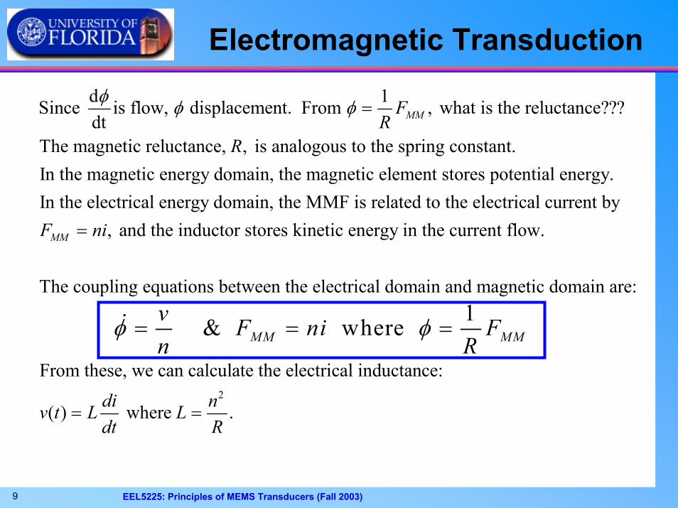
EEL5225: Principles of MEMS Transducers (Fall 2003)9
Electromagnetic Transductiond 1Since is flow, displacement. From , what is the reluctance???dt
The magnetic reluctance, , is analogous to the spring constant.In the magnetic energy domain, the magnetic element stores po
MMFRR
φ φ φ =
tential energy.In the electrical energy domain, the MMF is related to the electrical current by
, and the inductor stores kinetic energy in the current flow.
The coupling equations between the ele
MMF ni=
2
ctrical domain and magnetic domain are:
From these, we can calculate the electrical inductance:
( ) where .di nv t L Ldt R
= =
1 & where MM MMv F ni Fn R
φ φ= = =
EEL5225: Principles of MEMS Transducers (Fall 2003)10
φdfφ
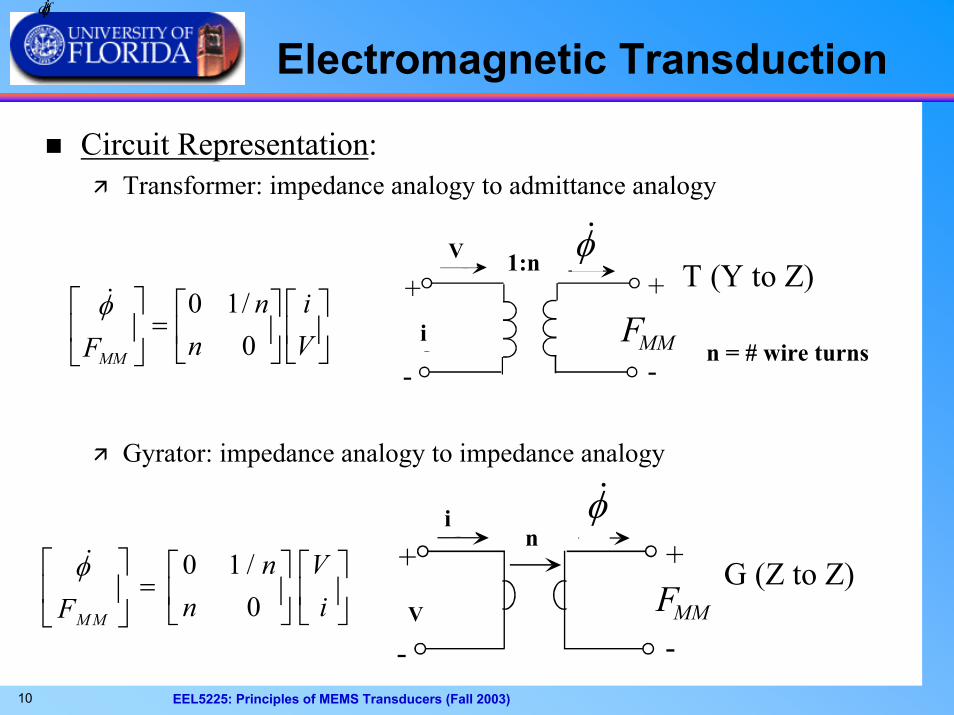
Electromagnetic Transduction
Circuit Representation:Transformer: impedance analogy to admittance analogy
Gyrator: impedance analogy to impedance analogy
T (Y to Z)
G (Z to Z)
n = # wire turns-
+
-
+e2
f2
e1
n:1f1
i
V 1:n
MMF
-
+
-
+e2
f2
e1
rf1
V
in
φ
MMF
0 1/0MM
n in VF
φ =
φ
0 1 /0MM
n Vn iF
φ =
EEL5225: Principles of MEMS Transducers (Fall 2003)11
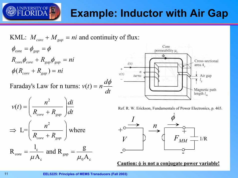
Example: Inductor with Air Gap
core
2
2
core
KML: and continuity of flux:
( )
Faraday's Law for n turns: ( )
( )
L= where
R
core gap
gap
core core gap gap
core gap
core gap
core gap
M M ni
R R niR R ni
dv t ndt
n div tR R dt
nR R
φ φ φ
φ φ
φ
φ
+ =
= =
+ =
+ =
=
= +
⇒ +
= cgap
c 0 c
l g and RA Aµ µ
=
Ref. R. W. Erickson, Fundamentals of Power Electronics, p. 465.
Caution: φ is not a conjugate power variable!
-
+
-
+V FMM
In
φ
1/R
EEL5225: Principles of MEMS Transducers (Fall 2003)12
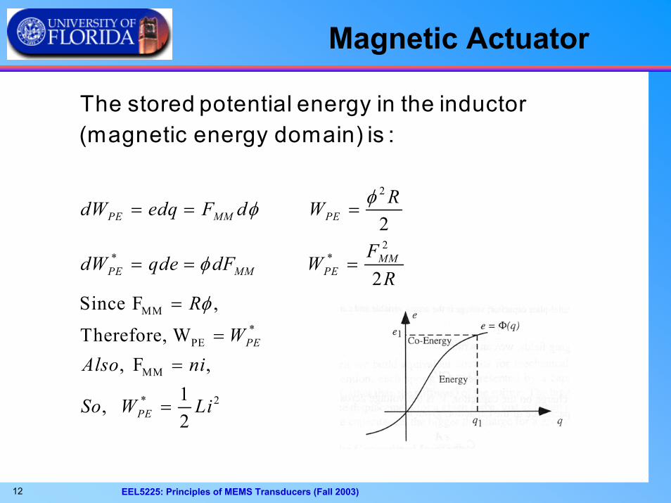
Magnetic Actuator
2
2* *
MM*
PE
MM
* 2
2
2
Since F ,
Therefore, W, F ,
1, 2
PE MM PE
MMPE MM PE
PE
PE
RdW edq F d W
FdW qde dF W
RR
WAlso ni
So W Li
φφ
φ
φ
= = =
= = =
=
==
=
The stored potential energy in the inductor (magnetic energy domain) is :
EEL5225: Principles of MEMS Transducers (Fall 2003)13
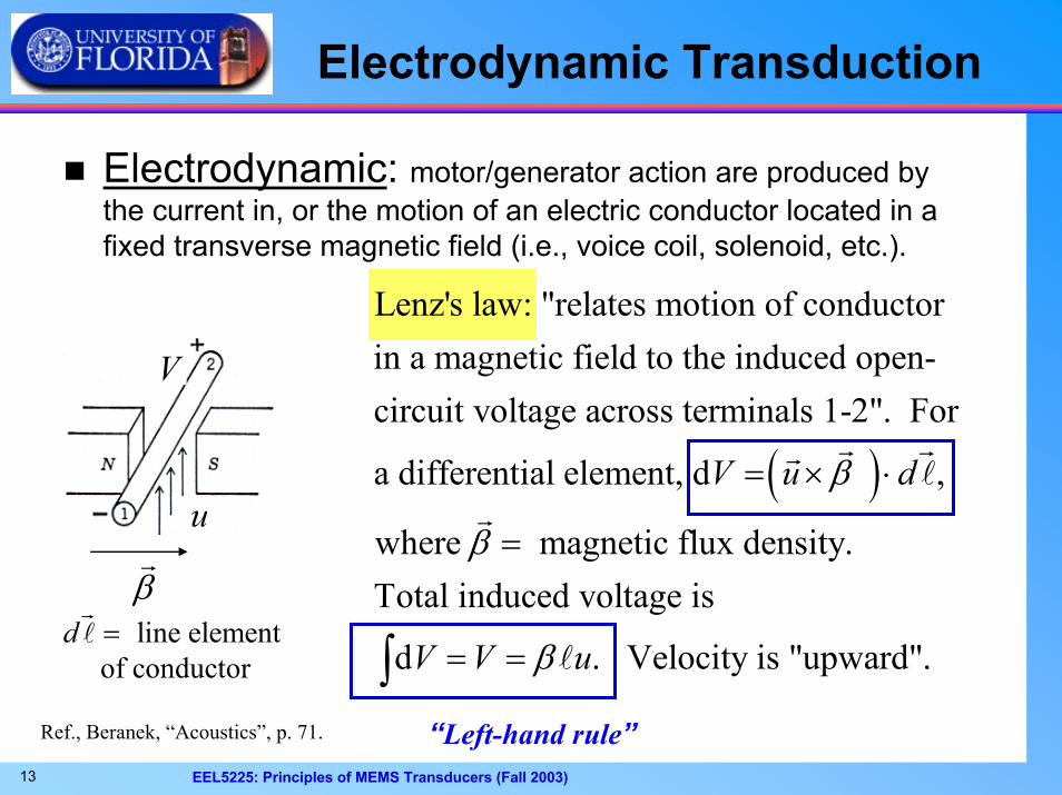
Electrodynamic Transduction
( )
Lenz's law: "relates motion of conductorin a magnetic field to the induced open-circuit voltage across terminals 1-2". For
a differential element, d ,
where magnetic flux density. Tota
V u dβ
β
= × ⋅
=l induced voltage is
d . Velocity is "upward".V V uβ= =∫
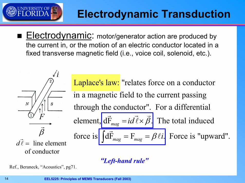
Electrodynamic: motor/generator action are produced by the current in, or the motion of an electric conductor located in a fixed transverse magnetic field (i.e., voice coil, solenoid, etc.).
line element of conductor
d =
V
u
β
“Left-hand rule”Ref., Beranek, “Acoustics”, p. 71.
EEL5225: Principles of MEMS Transducers (Fall 2003)14
Electrodynamic Transduction
Electrodynamic: motor/generator action are produced by the current in, or the motion of an electric conductor located in a fixed transverse magnetic field (i.e., voice coil, solenoid, etc.).
Laplace's law: "relates force on a conductorin a magnetic field to the current passingthrough the conductor". For a differential
element, dF . The total induced
force is dF F . mag
mag mag
id
i
β
β
= ×
= =∫ Force is "upward". line element
of conductord =
F
i
β
“Left-hand rule”Ref., Beraneck, “Acoustics”, pg71.
EEL5225: Principles of MEMS Transducers (Fall 2003)15
Electrodynamic Transduction
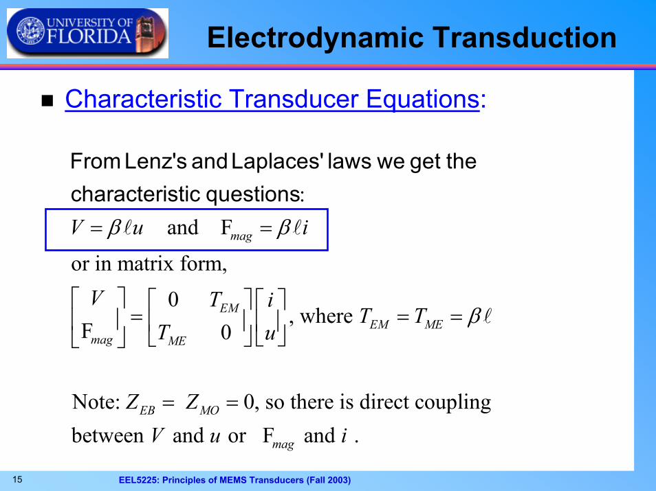
Characteristic Transducer Equations:
: and F
or in matrix form,
0, where
F 0
Note: 0, so there is direc
mag
EMEM ME
mag ME
EB MO
V u i
V T iT T
T u
Z Z
β β
β
= =
= = =
= =
From Lenz's and Laplaces' laws we get the characteristic questions
t coupling between and or F and .magV u i
EEL5225: Principles of MEMS Transducers (Fall 2003)16
Electrodynamic Transduction
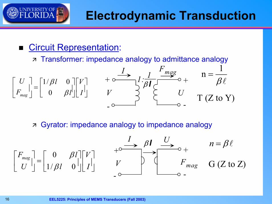
Circuit Representation:Transformer: impedance analogy to admittance analogy
Gyrator: impedance analogy to impedance analogy
1nβ
=
-
+
-
+Fmag
U
V
β lI
-
+
-
+1:β l1
V
I
U
Fmag
T (Z to Y)
G (Z to Z)
n β=
1/ 00mag
U l VF l I
ββ
=
01/ 0
magF l VU l I
ββ
=
EEL5225: Principles of MEMS Transducers (Fall 2003)17
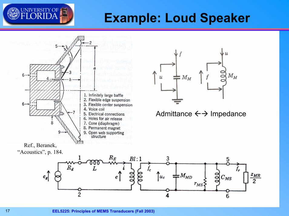
Example: Loud Speaker
Ref., Beranek, “Acoustics”, p. 184.
Admittance Impedance