PIC-microcontroller projects list: 954 pic-microcontroller projects

1Week 10© Vocational Training Council, Hong Kong.
Simple I/O InterfacingSimple I/O Interfacing
EEE3410 Microcontroller ApplicationsDepartment of Electrical Engineering
Lecture 9

2Week 9© Vocational Training Council, Hong Kong.
EEE3410 Microcontroller Applications
Interface 8051 with the following Input/Output Devices
Switches
Solenoid and relays
LEDs
Seven Segment Display
Dot matrix display
In this Lecture In this Lecture ……..
3Week 9© Vocational Training Council, Hong Kong.
EEE3410 Microcontroller Applications
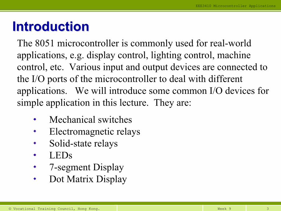
Mechanical switchesElectromagnetic relaysSolid-state relaysLEDs7-segment DisplayDot Matrix Display
IntroductionIntroductionThe 8051 microcontroller is commonly used for real-world applications, e.g. display control, lighting control, machine control, etc. Various input and output devices are connected tothe I/O ports of the microcontroller to deal with different applications. We will introduce some common I/O devices for simple application in this lecture. They are:

4Week 9© Vocational Training Council, Hong Kong.
EEE3410 Microcontroller Applications
Mechanical switches are common input devices
One or more pairs of contacts that can be open or close.
Typical switch designations are:
SPST (single-pole-single-throw)
SPDT (single-pole-double-throw)
DPDT (double-pole-double-throw)
Normally open (N.O.) contacts close when the switch is activated and normally close (N.C.) contacts close when the switch is activated.
Mechanical SwitchesMechanical Switches
N.O. SPST
N.O. DPST
N.O. DPST

5Week 9© Vocational Training Council, Hong Kong.
EEE3410 Microcontroller Applications
Connect mechanical switches to 8051Connect mechanical switches to 8051+5V
8051
EA VCC
Reset
XTAL1
XTAL2
VSS
P3.7
P3.6
P3.5
P3.4
SW1
SW2
SW3
SW4
SW opens, input to 8051 is HIGH (1)SW closes, input to 8051 is LOW (0)
ORG 0000H:JNB P3.7,
CASE1 JNB P3.6, CASE2
JNB P3.5, CASE3
JNB P3.4, CASE4
::
CASE1: ::
CASE2: ::
CASE3: ::
CASE4: ::
Check the status of SW1
Figure 9.1

6Week 9© Vocational Training Council, Hong Kong.
EEE3410 Microcontroller Applications
Electromagnetic RelaysElectromagnetic RelaysElectromagnetic relay consists of two parts - solenoid and relay contacts
Solenoid is a coil of wire used to produce a magnetic field to move a steel actuator where points of contacts are located.
The actuator is used to close/open the contact points, such construction is called a relay.
Figure 9.2 construction of a Electromagnetic relay

7Week 9© Vocational Training Council, Hong Kong.
EEE3410 Microcontroller Applications
Driving an Electromagnetic RelaysDriving an Electromagnetic RelaysFigure 9.3 show a typical driving circuit of an electromagnetic relay.
The transistor will act as a switch to allow current passing through the solenoid.
The diode placed across the coil terminal is to protect the transistor damaged from spike voltage during ON/OFF.
The external circuit connected to relay terminals will be turned ON/OFF by the TTL.
Contact closed if TTL = HighContact opened if TTL = Low
+5V
Vs
Figure 9.3 Driving circuit of an electromagnetic relay
TTL

8Week 9© Vocational Training Council, Hong Kong.
EEE3410 Microcontroller Applications
Solid State Relays/SwitchesSolid State Relays/SwitchesSolid-state relays has no mechanical parts and made of semi-conductor materials
It combines the isolation, driving, and contact closure functions into a single package
It is commonly use to control ac loads
Relay closed if input = High
Relay opened if input = Low
SSR+
−
T1
T2
a.c. power supply
Figure 9.4 Driving a solid state relay
Input Control
9Week 9© Vocational Training Council, Hong Kong.
EEE3410 Microcontroller Applications
LightLight--Emitting Diode (LED)Emitting Diode (LED)
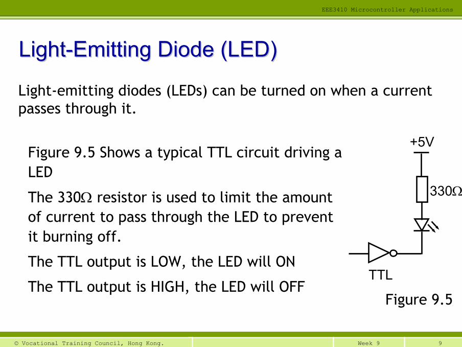
Light-emitting diodes (LEDs) can be turned on when a current passes through it.
Figure 9.5 Shows a typical TTL circuit driving a LED
The 330Ω resistor is used to limit the amount of current to pass through the LED to prevent it burning off.
The TTL output is LOW, the LED will ON
The TTL output is HIGH, the LED will OFF
+5V
TTL
Figure 9.5
330Ω

10Week 9© Vocational Training Council, Hong Kong.
EEE3410 Microcontroller Applications
Control of Control of LEDsLEDs
P1.7
P1.6
P1.5
P1.4
P1.3
P1.2
P1.1
P1.0
+5V
8051
EA VCC
Reset
XTAL1
XTAL2
VSS
• 8 LEDs are connected to Port 1and linked to 5V supply
• The LEDs can directly be turned ON/OFF by the 8051
• Under this connection, the LEDswill be
OFF when port bit is at logic 1
ON when port bit is at logic 0
Figure 9.6

11Week 9© Vocational Training Council, Hong Kong.
EEE3410 Microcontroller Applications
Example 9.1 :Example 9.1 : Control the 8 Control the 8 LEDsLEDs ON/OFF at the same timeON/OFF at the same time
All LEDs ON
All LEDs OFF

12Week 9© Vocational Training Council, Hong Kong.
EEE3410 Microcontroller Applications
Program Listing for Example 9.1Program Listing for Example 9.1
ORG 0000HCLR A
LOOP: MOV P1, ACPL AACALL DELAYAJMP LOOP
DELAY: MOV R6, #250DL1: MOV R7, #200DL2: DJNZ R7, DL2
DJNZ R6, DL1RETEND
Start
Set A = 00
Move the content of A to P1
Delay for 0.1s
Invert the content of A
Assume 12MHz clock, determine the delay time.

13Week 9© Vocational Training Council, Hong Kong.
EEE3410 Microcontroller Applications
ORG 0000HSTART: MOV R1, #07H
MOV A, #11111110BLEFT: MOV P1, A
ACALL DELAYRL ADJNZ R1, LEFT;MOV R1, #07HMOV A, #01111111B
RIGHT: MOV P1, AACALL DELAYRR ADJNZ R1, RIGHTAJMP START;
DELAY: ……….
Example 9.2 : Example 9.2 : Glowing a LED in rotating sequenceGlowing a LED in rotating sequence
14Week 9© Vocational Training Council, Hong Kong.
EEE3410 Microcontroller Applications
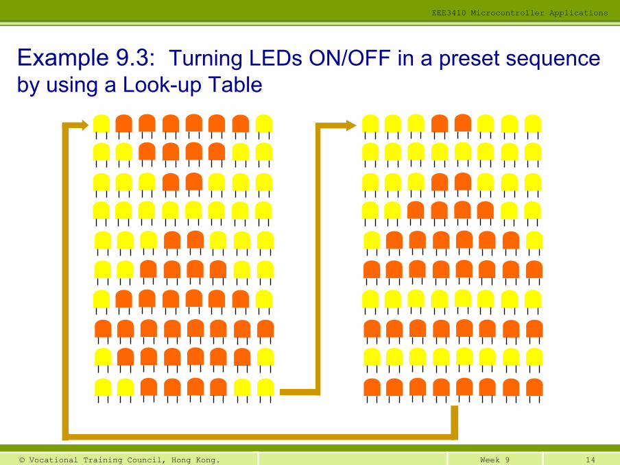
Example 9.3: Turning LEDs ON/OFF in a preset sequence by using a Look-up Table
15Week 9© Vocational Training Council, Hong Kong.
EEE3410 Microcontroller Applications
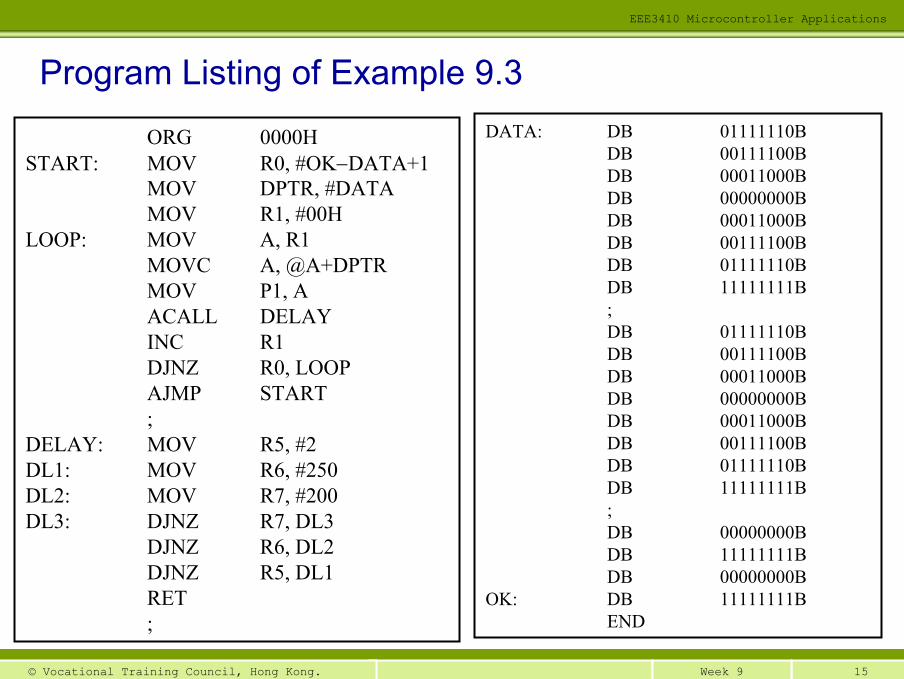
Program Listing of Example 9.3
ORG 0000HSTART: MOV R0, #OK−DATA+1
MOV DPTR, #DATAMOV R1, #00H
LOOP: MOV A, R1MOVC A, @A+DPTRMOV P1, AACALL DELAYINC R1DJNZ R0, LOOPAJMP START;
DELAY: MOV R5, #2DL1: MOV R6, #250DL2: MOV R7, #200DL3: DJNZ R7, DL3
DJNZ R6, DL2DJNZ R5, DL1RET;
DATA: DB 01111110BDB 00111100BDB 00011000BDB 00000000BDB 00011000BDB 00111100BDB 01111110BDB 11111111B;DB 01111110BDB 00111100BDB 00011000BDB 00000000BDB 00011000BDB 00111100BDB 01111110BDB 11111111B;DB 00000000BDB 11111111BDB 00000000B
OK: DB 11111111BEND

16Week 9© Vocational Training Council, Hong Kong.
EEE3410 Microcontroller Applications
Exercise: Write a 8051 program, using a look-up table, tolight-up the LEDs in the sequence as shown below

17Week 9© Vocational Training Council, Hong Kong.
EEE3410 Microcontroller Applications
Simple I/O applicationsSimple I/O applications
P1.7
P1.6
P1.5
P1.4
P1.3
P1.2
P1.1
P1.0
+5V
8051
EA VCC
Reset
XTAL1
XTAL2
VSS
P3.7
P3.6
P3.5
P3.4
SW1
SW2
SW3
SW4
Figure 9.7

18Week 9© Vocational Training Council, Hong Kong.
EEE3410 Microcontroller Applications
When SW1 Closed
When SW3 Closed When SW4 Closed
When SW2 Closed
Priority: SW1 SW2 SW3 SW4
Example 9.4: Refer to the 8051 circuit in figure 9.5, write a 8051 program to light-up the LEDs in the pattern as shown below when the respect switch is closed.

19Week 9© Vocational Training Council, Hong Kong.
EEE3410 Microcontroller Applications
Flow Chart of Example 9.4
Start
Initialization
Set P3 as input port
Read SW1∼SW4 status
SW1 closed?
SW2 closed?
SW3closed?
SW4 closed?
SW1 HandlerY
SW2 HandlerY
SW3 HandlerY
SW4 HandlerY
2
1
21
N
N
N

20Week 9© Vocational Training Council, Hong Kong.
EEE3410 Microcontroller Applications
Program Listing of Example 9.4
ORG 0000HMOV R1, #00000000BMOV R2, #01010101BMOV R3, #00001111BMOV R4, #11110000B;
TEST: ORL P3, #0FFHJNB P3.7, CASE1JNB P3.6, CASE2JNB P3.5, CASE3JNB P3.4, CASE4AJMP TEST;
CASE1: MOV A, R1MOV P1, AACALL DELAYXRL A, #11111111BMOV P1, AAJMP TEST;
CASE2 MOV A, R2MOV P1, AACALL DELAYXRL A, #10101010B
MOV P1, AAJMP TEST;
CASE3 MOV A, R3MOV P1, AACALL DELAYXRL A, #11110000BMOV P1, AAJMP TEST;
CASE4 MOV A, R4MOV P1, AACALL DELAYXRL A, #00001111BMOV P1, AAJMP TEST;
DELAY: ………..END

21Week 9© Vocational Training Council, Hong Kong.
EEE3410 Microcontroller Applications
A single-character display panel
Contains 7 LED segments arranged as an “8”
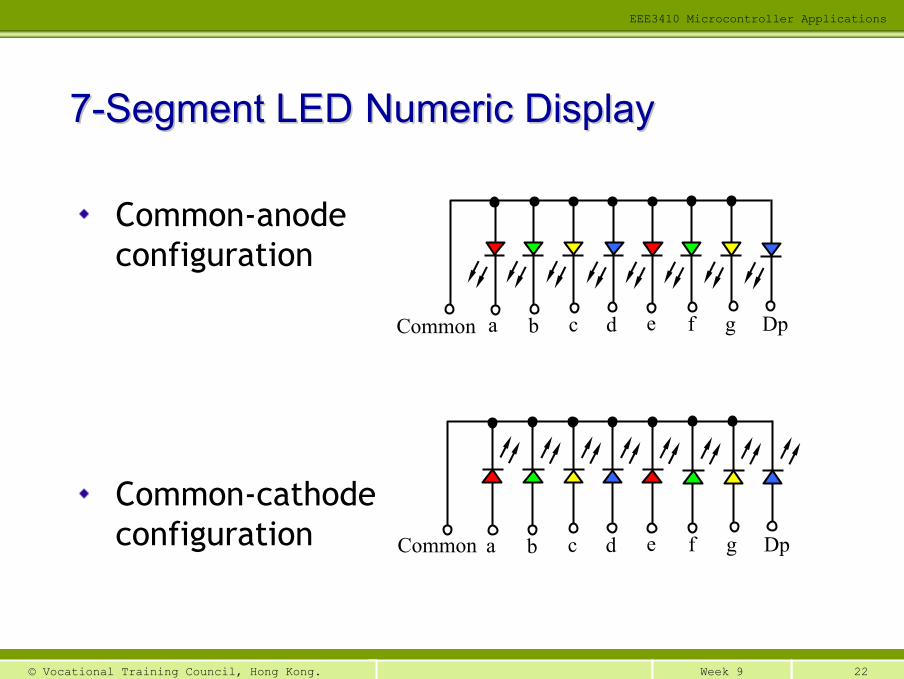
Two configurations: common-anode and common-cathode
77--Segment LED Numeric DisplaySegment LED Numeric Display
a
b
c
d
e
f g
Segment Pattern
Dp
22Week 9© Vocational Training Council, Hong Kong.
EEE3410 Microcontroller Applications
Common-anode configuration
Common-cathode configuration
77--Segment LEDSegment LED Numeric DisplayNumeric Display
a b c d e f g DpCommon
a b c d e f g DpCommon
23Week 9© Vocational Training Council, Hong Kong.
EEE3410 Microcontroller Applications
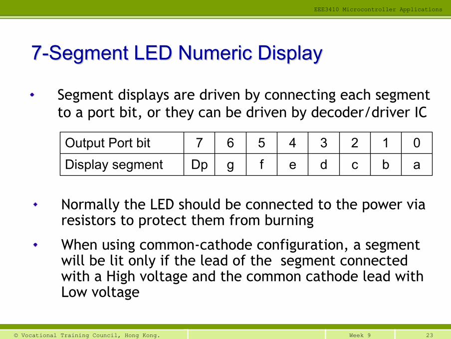
Segment displays are driven by connecting each segment to a port bit, or they can be driven by decoder/driver IC
77--Segment LED Numeric DisplaySegment LED Numeric Display
abcdefgDpDisplay segment01234567Output Port bit
Normally the LED should be connected to the power via resistors to protect them from burning
When using common-cathode configuration, a segment will be lit only if the lead of the segment connected with a High voltage and the common cathode lead with Low voltage

24Week 9© Vocational Training Council, Hong Kong.
EEE3410 Microcontroller Applications
77--Segment LED Numeric DisplaySegment LED Numeric Display
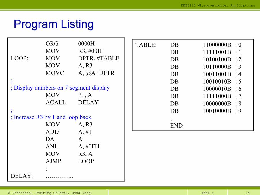
Use R3 as counter, write a 8051 assembly language program using look-up table method, to display the value in R3 to a 7-segment display
8051
bc
defg
aXTAL1
XTAL2
P2.0P2.1P2.2P2.3P2.4P2.5P2.6P2.7
Figure 9.8
Vcc
a
b
c
d
e
fg
Dp.
Dp.
25Week 9© Vocational Training Council, Hong Kong.
EEE3410 Microcontroller Applications
Program ListingProgram ListingORG 0000HMOV R3, #00H
LOOP: MOV DPTR, #TABLEMOV A, R3MOVC A, @A+DPTR
;; Display numbers on 7-segment display
MOV P1, AACALL DELAY
;; Increase R3 by 1 and loop back
MOV A, R3ADD A, #1DA AANL A, #0FHMOV R3, AAJMP LOOP;
DELAY: …………..
TABLE: DB 11000000B ; 0DB 11111001B ; 1DB 10100100B ; 2DB 10110000B ; 3DB 10011001B ; 4DB 10010010B ; 5DB 10000010B ; 6DB 11111000B ; 7DB 10000000B ; 8DB 10010000B ; 9;END

26Week 9© Vocational Training Council, Hong Kong.
EEE3410 Microcontroller Applications
Consists of a number of LED arranged in the form of a matrix
e.g. 35 LED in a 5 columns x 7 rows matrix, or 64 LED in a 8 x 8 matrix
To display a digit/character, use the method of scanning
cdefg
a
1 2 3 4 5
b
i.e. scan a column at a time. If the scanning is fast enough, it “appears” that the digit/character is displayed (due to illusion of our eyes)
DotDot--matrix LED Displaymatrix LED Display

27Week 9© Vocational Training Council, Hong Kong.
EEE3410 Microcontroller Applications
Internal circuitry of a 5 x 7 dot matrix display is shown on the right
Voltage should be supplied to terminals C and 1 to light up the LED indicated in this picture
DotDot--matrix LED Displaymatrix LED Display
c
d
e
f
g
a
b
1 2 3 4 5

28Week 9© Vocational Training Council, Hong Kong.
EEE3410 Microcontroller Applications
P3.0
P3.1
P3.2
P3.3
P3.4
P3.5
P3.6
8051
Reset
XTAL1
XTAL2
VSS
EA Vcc
P1.0
P1.1
P1.2
P1.3
P1.4
cdefg
ab
1 2 3 4 5
DotDot--matrix LED Displaymatrix LED Display
29Week 9© Vocational Training Council, Hong Kong.
EEE3410 Microcontroller Applications
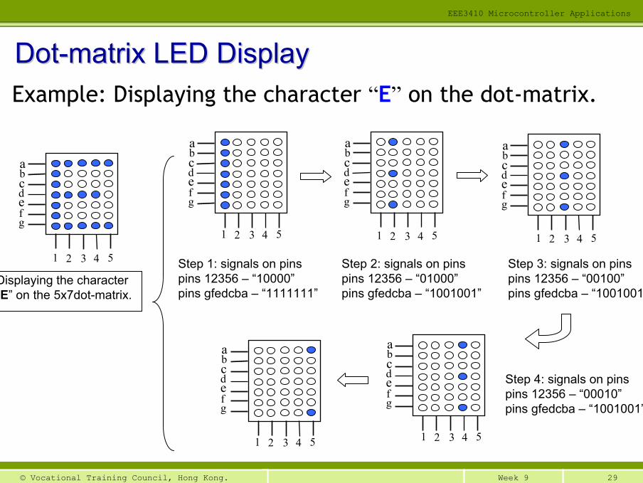
Example: Displaying the character “E” on the dot-matrix.
DotDot--matrix LED Displaymatrix LED Display
bcdefg
a
1 2 3 4 5
Displaying the character “E” on the 5x7dot-matrix.
Step 1: signals on pinspins 12356 – “10000”pins gfedcba – “1111111”
Step 2: signals on pinspins 12356 – “01000”pins gfedcba – “1001001”
Step 3: signals on pinspins 12356 – “00100”pins gfedcba – “1001001”
Step 4: signals on pinspins 12356 – “00010”pins gfedcba – “1001001”
bcdefg
a
1 2 3 4 5 1 2 3 4 5
bcdefg
a
1 2 3 4 5
bcdefg
a
1 2 3 4 5
bcdefg
a
1 2 3 4 5
bcdefg
a

30Week 9© Vocational Training Council, Hong Kong.
EEE3410 Microcontroller Applications
Code Words and Displays of Code Words and Displays of ‘‘00’’ to to ‘‘44’’00
1111
10B
0101
0001
B01
0010
01B
0100
0101
B00
1111
10B
0000
0000
B01
0000
10B
0111
1111
B01
0000
00B
0000
0000
B
0100
0110
B01
1000
01B
0101
0001
B01
0010
01B
0100
0110
B
0010
0001
B01
0000
01B
0100
1001
B01
0011
01B
0011
0011
B
0001
1000
B00
0101
00B
0001
0010
B01
1111
11B
0001
0000
B

31Week 9© Vocational Training Council, Hong Kong.
EEE3410 Microcontroller Applications
Code Words and Displays of Code Words and Displays of ‘‘55’’ to to ‘‘99’’00
1001
11B
0100
0101
B01
0001
01B
0100
0101
B00
1110
01B
0011
1100
B01
0010
10B
0100
1001
B01
0010
01B
0011
0000
B
0000
0001
B01
1111
10B
0111
1001
B00
0001
01B
0000
0011
B
0011
0110
B01
0010
01B
0100
1001
B01
0010
01B
0011
0110
B
0000
0110
B
0100
1001
B
0100
1001
B00
1010
01B
0001
1110
B

32Week 9© Vocational Training Council, Hong Kong.
EEE3410 Microcontroller Applications
Program Listing Program Listing –– character display on 5x7 Dotcharacter display on 5x7 Dot--matrix display matrix display (1/2)(1/2)
ORG 0000HSTART: MOV DPTR, #TABLE ; point to the starting add of 1st char
MOV R3, #10 ; display 10 charactersLOOP: MOV R2, #100 ; scan 100 times for each characterSCAN: ACALL SACN1 ; 10ms x 100 = 1000ms
DJNZ R2, SCANINC DPTR ; increase DPTR by 5 toINC DPTR ; point to the starting address ofINC DPTR ; the next characterINC DPTRINC DPTRDJNZ R3, LOOP ; loop back to display 10 charAJMP START; ======================; == Scan Subroutine ==; ======================
SCAN1 MOV R1, #00H ; R1 points to the starting add of a charMOV R5, #11111110B ; start from the leftmost columnMOV R4, #05 ; there are 5 columns
LOOP1 MOV A, R1 ; get the code at add R1+DPTRMOVC A, @A+DPTRMOV P3, A ; send the code to the dot-matrix displayMOV P1, R5 ; turn-on a particular transistor

33Week 9© Vocational Training Council, Hong Kong.
EEE3410 Microcontroller Applications
MOV R6, #5 ; delay for 2msDL1: MOV R7, #200DL2: DJNZ R7, DL2
DJNZ R6, DL1ORL P1, #11111111B ; turn-off displayMOV A, R5 ; RL A ; move to next columnMOV R5, A ; totally there are 5 columnsINC R1 ;DJNZ R4, LOOP1 ;RET ; return the main program; ============================; == Character Table ==; ============================
TABLE: DB 00111110B ; codes for 0DB 01010001BDB 01001001BDB 01000101BDB 00111110BDB 00000000B ; code for 1: ; codes for 2 to 9: ;END
Program Listing Program Listing –– character display on 5x7 Dotcharacter display on 5x7 Dot--matrix display matrix display (2/2)(2/2)

1Week 10© Vocational Training Council, Hong Kong.
Simple I/O InterfacingSimple I/O Interfacing
EEE3410 Microcontroller ApplicationsDepartment of Electrical Engineering
END of Lecture 9