EECS150 - Digital Design Lecture 21 - Design Blockscs150/sp12/agenda/lec/lec21-db3.pdf · EECS150 -...
20
Spring 2012 EECS150 - Lec21-db3 Page EECS150 - Digital Design Lecture 21 - Design Blocks April 3, 2012 John Wawrzynek 1
Transcript of EECS150 - Digital Design Lecture 21 - Design Blockscs150/sp12/agenda/lec/lec21-db3.pdf · EECS150 -...

Spring 2012 EECS150 - Lec21-db3 Page
EECS150 - Digital DesignLecture 21 - Design Blocks
April 3, 2012John Wawrzynek
1

• “fixed” shifters “hardwire” the shift amount into the circuit.
• Ex: verilog: X >> 2 – (right shift X by 2 places)
• Fixed shift/rotator is nothing but wires!
So what?
Spring 2012 EECS150 - Lec21-db3 Page
Fixed Shifters / Rotators
LogicalShift
Rotate
ArithmeticShift
2
Spring 2012 EECS150 - Lec21-db3 Page
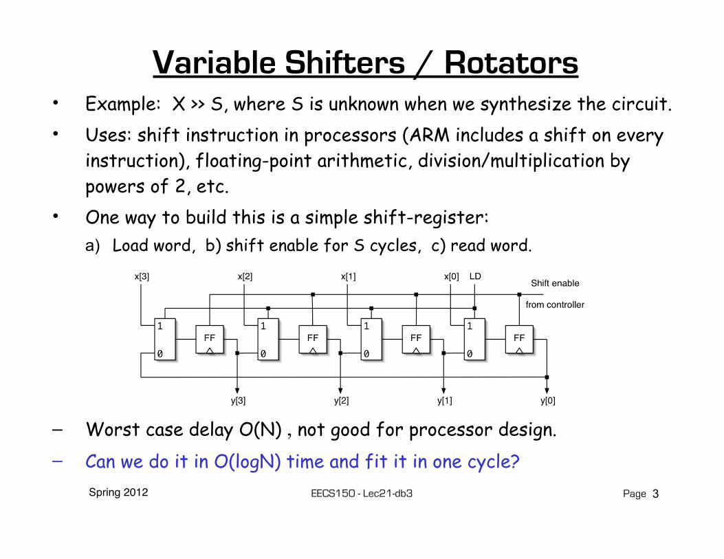
Variable Shifters / Rotators• Example: X >> S, where S is unknown when we synthesize the circuit.• Uses: shift instruction in processors (ARM includes a shift on every
instruction), floating-point arithmetic, division/multiplication by powers of 2, etc.
• One way to build this is a simple shift-register:a) Load word, b) shift enable for S cycles, c) read word.
– Worst case delay O(N) , not good for processor design.– Can we do it in O(logN) time and fit it in one cycle?
3

Spring 2012 EECS150 - Lec21-db3 Page
Log Shifter / Rotator• Log(N) stages, each shifts (or not) by a power of 2 places,
S=[s2;s1;s0]:
Shift by N/2
Shift by 2
Shift by 1
4

Spring 2012 EECS150 - Lec21-db3 Page
LUT Mapping of Log shifter
5
Efficient with 2to1 multiplexors, for instance, 3LUTs.
Virtex6 has 6LUTs. Naturally makes 4to1 muxes:
Reorganize shifter to use 4to1 muxes.
Final stage uses F7 mux
Spring 2012 EECS150 - Lec21-db3 Page
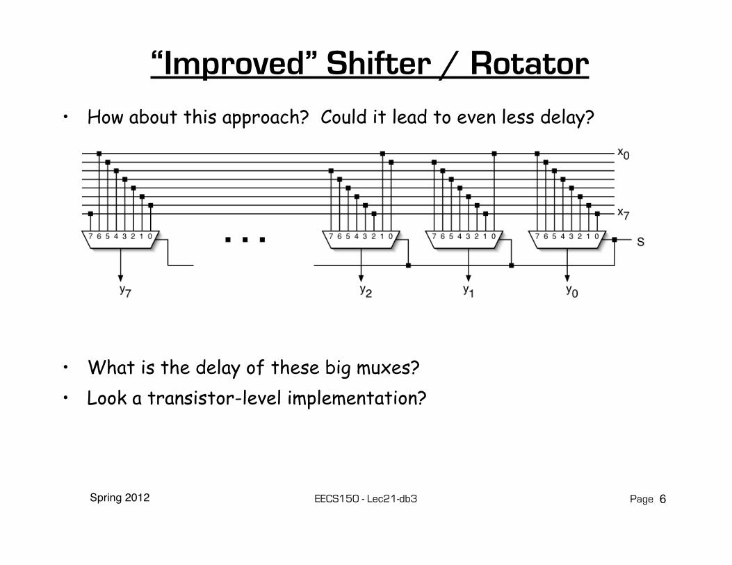
“Improved” Shifter / Rotator• How about this approach? Could it lead to even less delay?
• What is the delay of these big muxes?• Look a transistor-level implementation?
6
Spring 2012 EECS150 - Lec21-db3 Page
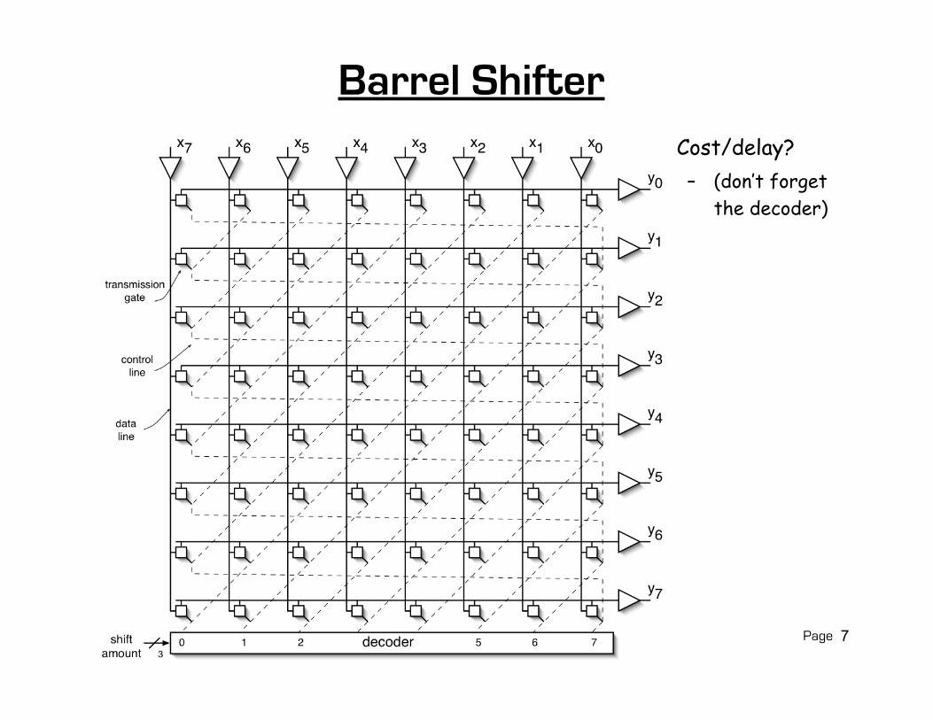
Barrel Shifter• Cost/delay?
– (don’t forget the decoder)
7
Spring 2012 EECS150 - Lec21-db3 Page
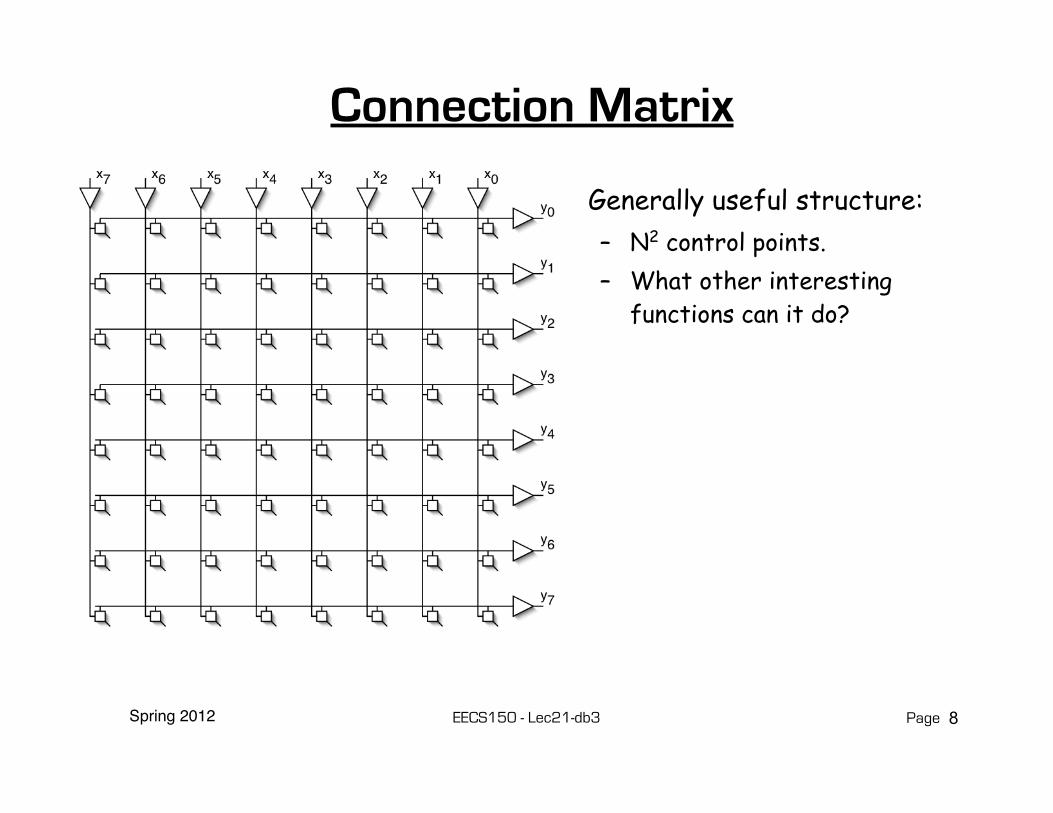
Connection Matrix
• Generally useful structure:– N2 control points. – What other interesting
functions can it do?
8

Spring 2012 EECS150 - Lec21-db3 Page
Cross-bar Switch• Nlog(N) control
signals.• Supports all
interesting permutations– All one-to-one and
one-to-many connections.
• Commonly used in communication hardware (switches, routers).
9

Spring 2012 EECS150 – Lec21-db3 Page
Linear Feedback Shift Registers (LFSRs)• These are n-bit counters exhibiting pseudo-random behavior.• Built from simple shift-registers with a small number of xor gates.• Used for:
– random number generation– counters– error checking and correction
• Advantages:– very little hardware– high speed operation
• Example 4-bit LFSR:
10

Spring 2012 EECS150 – Lec21-db3 Page
4-bit LFSR
• Circuit counts through 24-1 different non-zero bit patterns.
• Leftmost bit decides whether the “10011” xor pattern is used to compute the next value or if the register just shifts left.
• Can build a similar circuit with any number of FFs, may need more xor gates.
• In general, with n flip-flops, 2n-1 different non-zero bit patterns.
• (Intuitively, this is a counter that wraps around many times and in a strange way.)
11

Spring 2012 EECS150 – Lec21-db3 Page
Applications of LFSRs• Performance:
– In general, xors are only ever 2-input and never connect in series.
– Therefore the minimum clock period for these circuits is:
T > T2-input-xor + clock overhead– Very little latency, and independent
of n!• This can be used as a fast counter,
if the particular sequence of count values is not important. – Example: micro-code micro-pc
• Can be used as a random number generator. – Sequence is a pseudo-
random sequence:• numbers appear in a
random sequence• repeats every 2n-1 patterns
– Random numbers useful in:• computer graphics• cryptography• automatic testing
• Used for error detection and correction
• CRC (cyclic redundancy codes)
• ethernet uses them
12
Spring 2012 EECS150 – Lec21-db3 Page
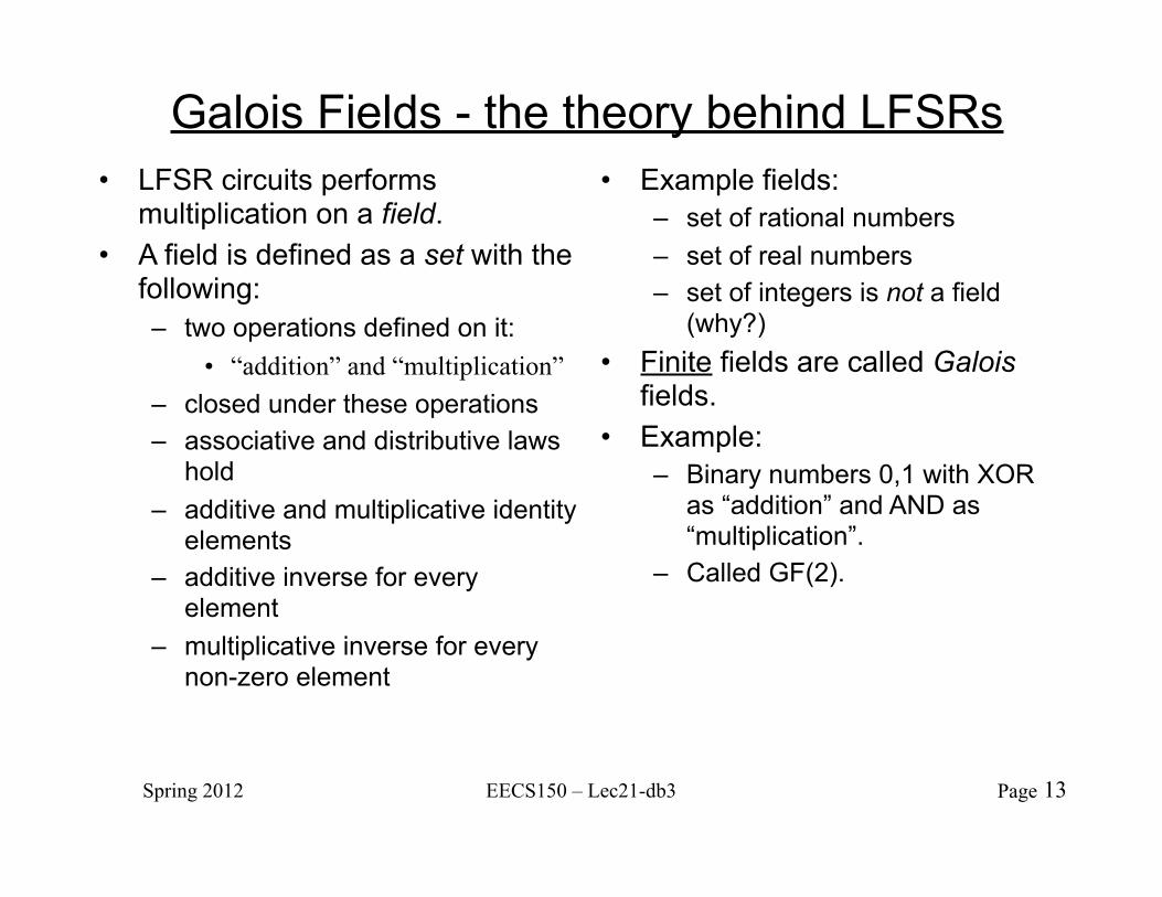
Galois Fields - the theory behind LFSRs• LFSR circuits performs
multiplication on a field.• A field is defined as a set with the
following:– two operations defined on it:
• “addition” and “multiplication”– closed under these operations – associative and distributive laws
hold– additive and multiplicative identity
elements– additive inverse for every
element– multiplicative inverse for every
non-zero element
• Example fields:– set of rational numbers– set of real numbers– set of integers is not a field
(why?)• Finite fields are called Galois
fields. • Example:
– Binary numbers 0,1 with XOR as “addition” and AND as “multiplication”.
– Called GF(2).
13
Spring 2012 EECS150 – Lec21-db3 Page
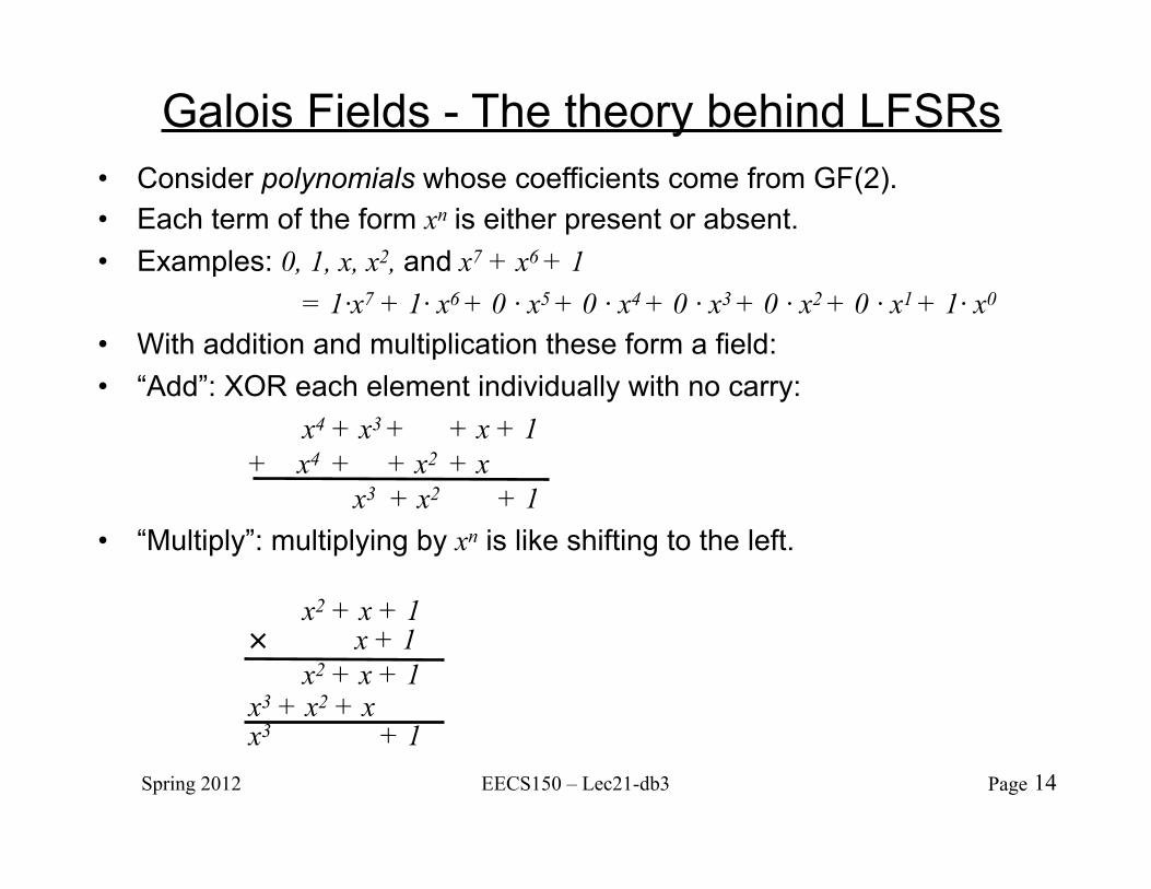
Galois Fields - The theory behind LFSRs• Consider polynomials whose coefficients come from GF(2).• Each term of the form xn is either present or absent.• Examples: 0, 1, x, x2, and x7 + x6 + 1 = 1·x7 + 1· x6 + 0 · x5 + 0 · x4 + 0 · x3 + 0 · x2 + 0 · x1 + 1· x0
• With addition and multiplication these form a field:• “Add”: XOR each element individually with no carry: x4 + x3 + + x + 1 + x4 + + x2 + x x3 + x2 + 1 • “Multiply”: multiplying by xn is like shifting to the left. x2 + x + 1 × x + 1 x2 + x + 1 x3 + x2 + x x3 + 1
14

Spring 2012 EECS150 – Lec21-db3 Page
Galois Fields - The theory behind LFSRs• These polynomials form a
Galois (finite) field if we take the results of this multiplication modulo a prime polynomial p(x).– A prime polynomial is one that
cannot be written as the product of two non-trivial polynomials q(x)r(x)
– Perform modulo operation by subtracting a (polynomial) multiple of p(x) from the result. If the multiple is 1, this corresponds to XOR-ing the result with p(x).
• For any degree, there exists at least one prime polynomial.
• With it we can form GF(2n)
• Additionally, …• Every Galois field has a primitive
element, α, such that all non-zero elements of the field can be expressed as a power of α. By raising α to powers (modulo p(x)), all non-zero field elements can be formed.
• Certain choices of p(x) make the simple polynomial x the primitive element. These polynomials are called primitive, and one exists for every degree.
• For example, x4 + x + 1 is primitive. So α = x is a primitive element and successive powers of α will generate all non-zero elements of GF(16). Example on next slide.
15

Spring 2012 EECS150 – Lec21-db3 Page
Galois Fields - The theory behind LFSRsα0 = 1α1 = xα2 = x2
α3 = x3
α4 = x + 1α5 = x2 + xα6 = x3 + x2
α7 = x3 + x + 1α8 = x2 + 1α9 = x3 + xα10 = x2 + x + 1α11 = x3 + x2 + x
α12 = x3 + x2 + x + 1α13 = x3 + x2 + 1α14 = x3 + 1α15 = 1
• Note this pattern of coefficients matches the bits from our 4-bit LFSR example.
• In general finding primitive polynomials is difficult. Most people just look them up in a table, such as:
α4 = x4 mod x4 + x + 1 = x4 xor x4 + x + 1 = x + 1
16
Spring 2012 EECS150 – Lec21-db3 Page
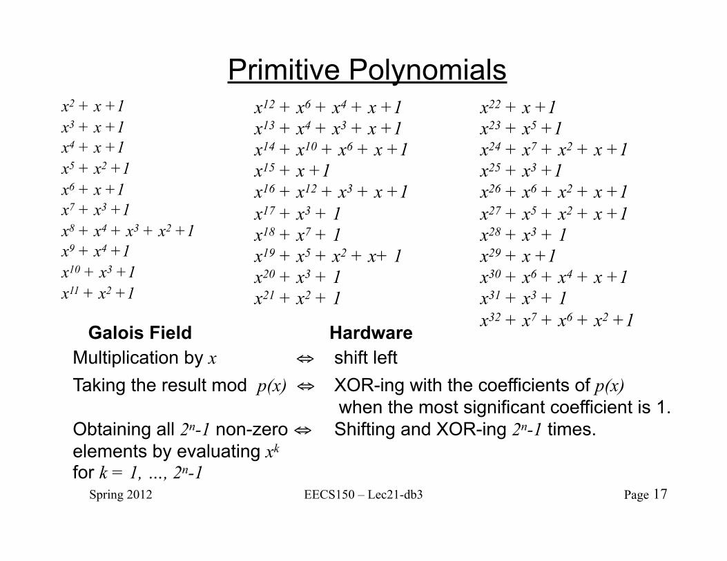
Primitive Polynomialsx2 + x +1x3 + x +1x4 + x +1x5 + x2 +1x6 + x +1x7 + x3 +1x8 + x4 + x3 + x2 +1x9 + x4 +1x10 + x3 +1x11 + x2 +1
x12 + x6 + x4 + x +1x13 + x4 + x3 + x +1x14 + x10 + x6 + x +1x15 + x +1x16 + x12 + x3 + x +1x17 + x3 + 1x18 + x7 + 1x19 + x5 + x2 + x+ 1x20 + x3 + 1x21 + x2 + 1
x22 + x +1x23 + x5 +1x24 + x7 + x2 + x +1x25 + x3 +1x26 + x6 + x2 + x +1x27 + x5 + x2 + x +1x28 + x3 + 1x29 + x +1x30 + x6 + x4 + x +1x31 + x3 + 1x32 + x7 + x6 + x2 +1
Galois Field HardwareMultiplication by x ⇔ shift leftTaking the result mod p(x) ⇔ XOR-ing with the coefficients of p(x) when the most significant coefficient is 1.Obtaining all 2n-1 non-zero ⇔ Shifting and XOR-ing 2n-1 times.elements by evaluating xk
for k = 1, …, 2n-1 17

Spring 2012 EECS150 – Lec21-db3 Page
Building an LFSR from a Primitive Polynomial• For k-bit LFSR number the flip-flops with FF1 on the right.• The feedback path comes from the Q output of the leftmost FF.• Find the primitive polynomial of the form xk + … + 1.• The x0 = 1 term corresponds to connecting the feedback directly to the D input
of FF 1.• Each term of the form xn corresponds to connecting an xor between FF n and n
+1.• 4-bit example, uses x4 + x + 1
– x4 ⇔ FF4’s Q output– x ⇔ xor between FF1 and FF2– 1 ⇔ FF1’s D input
• To build an 8-bit LFSR, use the primitive polynomial x8 + x4 + x3 + x2 + 1 and connect xors between FF2 and FF3, FF3 and FF4, and FF4 and FF5.
18

Spring 2012 EECS150 – Lec21-db3 Page
Error Correction with LFSRs
19
Spring 2012 EECS150 – Lec21-db3 Page
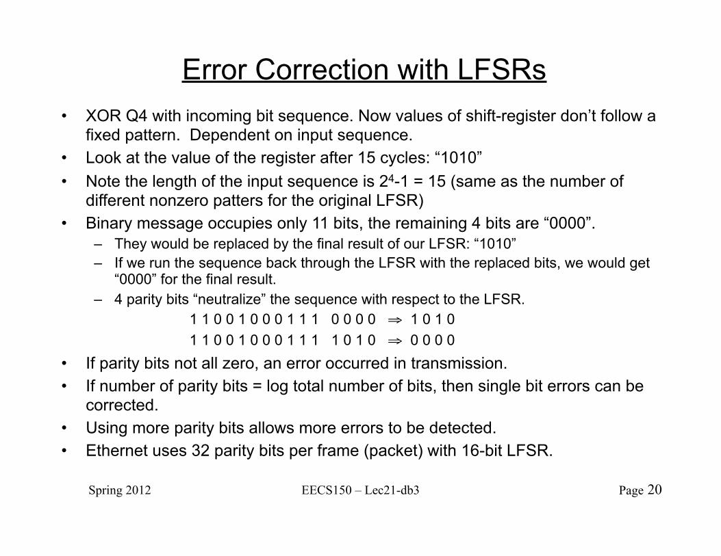
Error Correction with LFSRs• XOR Q4 with incoming bit sequence. Now values of shift-register don’t follow a
fixed pattern. Dependent on input sequence.• Look at the value of the register after 15 cycles: “1010”• Note the length of the input sequence is 24-1 = 15 (same as the number of
different nonzero patters for the original LFSR)• Binary message occupies only 11 bits, the remaining 4 bits are “0000”.
– They would be replaced by the final result of our LFSR: “1010”– If we run the sequence back through the LFSR with the replaced bits, we would get
“0000” for the final result.– 4 parity bits “neutralize” the sequence with respect to the LFSR. 1 1 0 0 1 0 0 0 1 1 1 0 0 0 0 ⇒ 1 0 1 0 1 1 0 0 1 0 0 0 1 1 1 1 0 1 0 ⇒ 0 0 0 0
• If parity bits not all zero, an error occurred in transmission.• If number of parity bits = log total number of bits, then single bit errors can be
corrected.• Using more parity bits allows more errors to be detected.• Ethernet uses 32 parity bits per frame (packet) with 16-bit LFSR.
20