EECS150 - Digital Design Lecture 12 - Video Interfacingcs150/sp13/agenda/lec/lec12-video.pdf ·...
12
Spring 2013 EECS150 - Lec12-video Page EECS150 - Digital Design Lecture 12 - Video Interfacing Feb 28, 2013 John Wawrzynek 1 Spring 2013 EECS150 - Lec12-video Page MIPS150 Video Subsystem 2 • Gives software ability to display information on screen. • Equivalent to standard graphics cards: • Processor can directly write the display bit map • 2D Graphics acceleration
Transcript of EECS150 - Digital Design Lecture 12 - Video Interfacingcs150/sp13/agenda/lec/lec12-video.pdf ·...

Spring 2013 EECS150 - Lec12-video Page
EECS150 - Digital DesignLecture 12 - Video Interfacing
Feb 28, 2013John Wawrzynek
1
Spring 2013 EECS150 - Lec12-video Page
MIPS150 Video Subsystem
2
• Gives software ability to display information on screen.
• Equivalent to standard graphics cards:
• Processor can directly write the display bit map
• 2D Graphics acceleration

Spring 2013 EECS150 - Lec12-video Page
“Framebuffer” HW/SW Interface• A range of memory addresses correspond to the display.• CPU writes (using sw instruction) pixel values to change display.• No synchronization required. Independent process reads pixels from
memory and sends them to the display interface at the required rate.
0
0xFFFFFFFFCPU address map
3
Ex: 1024 pixels/line X 768 lines
0x80000000
0x803FFFFC Frame buffer Display Origin:
Increasing X values to the right. Increasing Y values down.
(0,0)
(1023, 767)
Spring 2013 EECS150 - Lec12-video Page
Framebuffer Implementation• Framebuffer like a simple dual-ported memory.
Two independent processes access framebuffer:
4
CPU writes pixel locations. Could be
in random order, e.g. drawing an object,
or sequentially, e.g. clearing the screen.
Video Interface continuously reads pixel locations in scan-line order and sends to physical display.
• How big is this memory and how do we implement it? For us: 1024 x 768 pixels/frame x 24 bits/pixel
Framebuffer
Spring 2013 EECS150 - Lec12-video Page
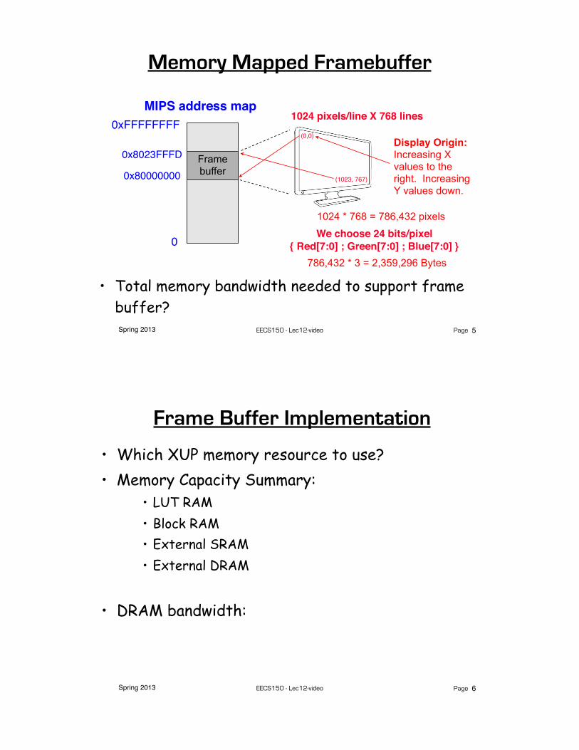
Memory Mapped Framebuffer
0
0xFFFFFFFFMIPS address map
5
1024 pixels/line X 768 lines
0x80000000
0x8023FFFD Frame buffer
Display Origin:Increasing X values to the right. Increasing Y values down.
(0,0)
(1023, 767)
1024 * 768 = 786,432 pixels
We choose 24 bits/pixel{ Red[7:0] ; Green[7:0] ; Blue[7:0] }
786,432 * 3 = 2,359,296 Bytes
• Total memory bandwidth needed to support frame buffer?
Spring 2013 EECS150 - Lec12-video Page
Frame Buffer Implementation
• Which XUP memory resource to use?• Memory Capacity Summary:
• LUT RAM• Block RAM• External SRAM• External DRAM
• DRAM bandwidth:
6

Spring 2013 EECS150 - Lec12-video Page
Framebuffer Details
7
XUP DRAM memory capacity: 256 MBytes (in external DRAM).
0
0xFFFFFFFFMIPS address map
768 lines, 1024 pixels/line
0x80000000
0x80240000Frame buffer
4K4K4K
4K...
= 786,432 pixel locations
Starting each line on a multiple of 4K leads to independent X and Y address: {Y[21:12] ; X[11:2]} Y == row number, X == pixel in row
1024 x 768 locations
With Byte addressed memory, best to use 4 Bytes/pixel
Spring 2013 EECS150 - Lec12-video Page
Frame Buffer Physical Interface
8
More generally, how does software interface to I/O devices?
CPU
VideoInterface
DRAM Controller / Hub
FPGA
Processor Side: provides a memory mapped programming interface to video display.
Video Interface Block: accepts pixel values from FB, streams pixels values and control signals to physical device.
DRAM “Hub”: arbitrates among multiple DRAM users.

Spring 2013 EECS150 - Lec12-video Page
Physical Video Interface
9
DVI connector:accommodates analog and digital formats
DVI Transmitter Chip, Chrontel 7301C.
Implements standard signaling voltage levels for video monitors. Digital to analog conversion for analog display formats.
Spring 2013 EECS150 - Lec12-video Page
Framebuffer Details 2009• One pixel value per memory location.
10
Virtex-5 LX110T memory capacity: 5,328 Kbits (in block RAMs).
0
0xFFFFFFFFMIPS address map 768 lines, 1K pixels/line
0x80000000
0x803FFFFC Frame buffer
1K1K1K
1K...
• Note, that with only 4 bits/pixel, we could assign more than one pixel per memory location. Ruled out by us, as it complicated software.
= 786,432 memory locations
(5,328 X 1024 bits) / 786432 = 6.9 bits/pixel max!
We choose 4 bits/pixel

Spring 2013 EECS150 - Lec12-video Page
Color Map
11
4 bits per pixel, allows software to assign each screen location, one of 16 different colors.
However, physical display interface uses 8 bits / pixel-color. Therefore entire pallet is 224 colors.
Color map is memory mapped to CPU address space, so software can set the color table. Addresses: 0x8040_0000 0x8040_003C, one 24-bit entry per memory address.
R G BR G BR G B
R G B...
24 bits
16 entries
pixel value from framebuffer
pixel color to video interface
Color Map converts 4 bit pixel values to 24 bit colors.
Spring 2013 EECS150 - Lec12-video Page
Memory Mapped Framebuffer 2010• A range of memory addresses correspond to the display.• CPU writes (using sw instruction) pixel values to change display.• No handshaking required. Independent process reads pixels from
memory and sends them to the display interface at the required rate.
0
0xFFFFFFFFMIPS address map
12
800 pixels/line X 600 lines
0x80000000
0x801D4BFC Frame buffer
Display Origin:Increasing X values to the right. Increasing Y values down.
(0,0)
(800, 600)
8Mbits / 480000 = 17.5 bits/pixel max!
We choose 16 bits/pixel{ Red[4:0] ; Green[5:0] ; Blue[4:0] }

Spring 2013 EECS150 - Lec12-video Page
Framebuffer Details 2010
13
XUP SRAM memory capacity: ~8 Mbits (in external SRAMs).
0
0xFFFFFFFFMIPS address map 600 lines, 800 pixels/line
0x80000000
0x803FFFFC Frame buffer
1K1K1K
1K...
• Note, that we assign only one 16 bit pixel per memory location.• Two pixel address map to one address in the SRAM (it is 32bits wide).• Only part of the mapped memory range occupied with physical memory.
= 480,000 memory locations
Starting each line on a multiple of 1K leads to independent X and Y address: {Y[9:0] ; X[9:0]} Y == row number, X == pixel in row
1024 x 768 locations
Spring 2013 EECS150 - Lec12-video Page
XUP Board External SRAM
14
More generally, how does software interface to I/O devices?
*ZBT (ZBT stands for zero bus turnaround) — the turnaround is the number of clock cycles it takes to change access to the SRAM from write to read and vice versa. The turnaround for ZBT SRAMs or the latency between read and write cycle is zero.
“ZBT” synchronous SRAM, 9 Mb on 32-bit data bus, with four “parity” bits256K x 36 bits(located under the removable LCD)

Spring 2013 EECS150 - Lec12-video Page
MIPS150 Video Subsystem
15
• Gives software ability to display information on screen.
• Equivalent to standard graphics cards:
• Processor can directly write the display bit map
• 2D Graphics acceleration
Spring 2013 EECS150 - Lec12-video Page
Graphics Software
16
clear: # a0 holds 4-bit pixel color # t0 holds the pixel pointer ori $t0, $0, 0x8000 # top half of frame address sll $t0, $t0, 16 # form framebuffer beginning address # t2 holds the framebuffer max address ori $t2, $0, 768 # 768 rows sll $t2, $t2, 12 # * 1K pixels/row * 4 Bytes/address addu $t2, $t2, $t0 # form ending address addiu $t2, $t2, -4 # minus one word address! # # the write loopL0: sw $a0, 0($t0) # write the pixel bneq $t0, $t2, L0 # loop until done addiu $t0, $t0, 4 # bump pointer! jr $ra
“Clearing” the screen - fill the entire screen with same color Remember Framebuffer base address: 0x8000_0000Size: 1024 x 768
How long does this take? What do we need to know to answer?How does this compare to the frame rate?

Spring 2013 EECS150 - Lec12-video Page
Optimized Clear Routine
17
clear:...
# the write loopL0: sw $a0, 0($t0) # write some pixels sw $a0, 4($t0) sw $a0, 8($t0) sw $a0, 12($t0) sw $a0, 16($t0) sw $a0, 20($t0) sw $a0, 24($t0) sw $a0, 28($t0) sw $a0, 32($t0) sw $a0, 36($t0) sw $a0, 40($t0) sw $a0, 44($t0) sw $a0, 48($t0) sw $a0, 52($t0) sw $a0, 56($t0) sw $a0, 60($t0) bneq $t0, $t2, L0 # loop until done addiu $t0, $t0, 64 # bump pointer jr $ra
What’s the performance of this one?
Amortizing the loop overhead.
Spring 2013 EECS150 - Lec12-video Page
Line Drawing
18
0
0 1 2 3 4 5 6 7 8 9 10 11 121234567
(x0,y0) (x1,y1)From toLine equation defines all the points:
For each x value, could compute y, with: then round to the nearest integer y value.
Slope can be precomputed, but still requires floating point * and + in the loop: slow or expensive!

Spring 2013 EECS150 - Lec12-video Page
Bresenham Line Drawing Algorithm
• Computers of the day, slow at complex arithmetic operations, such as multiply, especially on floating point numbers.
• Bresenham’s algorithm works with integers and without multiply or divide.
• Simplicity makes it appropriate for inexpensive hardware implementation.
• With extension, can be used for drawing circles.
19
Developed by Jack E. Bresenham in 1962 at IBM. "I was working in the computation lab at IBM's San Jose development lab. A Calcomp plotter had been attached to an IBM 1401 via the 1407 typewriter console. ...
Spring 2013 EECS150 - Lec12-video Page
Line Drawing Algorithm
20
This version assumes: x0 < x1, y0 < y1, slope =< 45 degreesfunction line(x0, x1, y0, y1) int deltax := x1 - x0 int deltay := y1 - y0 int error := deltax / 2 int y := y0 for x from x0 to x1 plot(x,y) error := error - deltay if error < 0 then y := y + 1 error := error + deltax
Note: error starts at deltax/2 and gets decremented by deltay for each x, y gets incremented when error goes negative, therefore y gets incremented at a rate proportional to deltax/deltay.
0 1 2 3 4 5 6 7 8 9 10 11 121234567

Spring 2013 EECS150 - Lec12-video Page
Line Drawing, Examples
21
0 1 2 3 4 5 6 7 8 9 10 11 121234567
deltay = 1 (very low slope). y only gets incremented once (halfway between x0 and x1)
0 1 2 3 4 5 6 7 8 9 10 11 121234567
deltay = deltax (45 degrees, max slope). y gets incremented for every x
Spring 2013 EECS150 - Lec12-video Page
Line Drawing Example
22
0 1 2 3 4 5 6 7 8 9 10 11 121234567
function line(x0, x1, y0, y1) int deltax := x1 - x0 int deltay := y1 - y0 int error := deltax / 2 int y := y0 for x from x0 to x1 plot(x,y) error := error - deltay if error < 0 then y := y + 1 error := error + deltax
deltax = 10, deltay = 4, error = 10/2 = 5, y = 1
(1,1) -> (11,5)
x = 1: plot(1,1)error = 5 - 4 = 1
x = 2: plot(2,1)error = 1 - 4 = -3 y = 1 + 1 = 2 error = -3 + 10 = 7
x = 3: plot(3,2)error = 7 - 4 = 3
x = 4: plot(4,2)error = 3 - 4 = -1 y = 2 + 1 = 3 error = -1 + 10 = 9
x = 5: plot(5,3)error = 9 - 4 = 5
x = 6: plot(6,3)error = 5 - 4 = 1
x = 7: plot(7,3)error = 1 - 4 = -3 y = 3 + 1 = 4 error = -3 + 10 -= 7

Spring 2013 EECS150 - Lec12-video Page
C Version
23
#define SWAP(x, y) (x ^= y ^= x ^= y)#define ABS(x) (((x)<0) ? -(x) : (x))
void line(int x0, int y0, int x1, int y1) { char steep = (ABS(y1 - y0) > ABS(x1 - x0)) ? 1 : 0; if (steep) { SWAP(x0, y0); SWAP(x1, y1); } if (x0 > x1) { SWAP(x0, x1); SWAP(y0, y1); } int deltax = x1 - x0; int deltay = ABS(y1 - y0); int error = deltax / 2; int ystep; int y = y0 int x; ystep = (y0 < y1) ? 1 : -1; for (x = x0; x <= x1; x++) { if (steep) plot(y,x); else plot(x,y); error = error - deltay; if (error < 0) { y += ystep; error += deltax; } }}
Modified to work in any quadrant and for any slope.
Estimate software performance (MIPS version)
What’s needed to do it in hardware?
Goal is one pixel per cycle. Pipelining might be necessary.
Spring 2013 EECS150 - Lec12-video Page
Hardware Implementation Notes
24
x0
y1
x1
0
32
0x8040_0040:0x8040_0044:
0x8040_0064:Read-only control register ready0x8040_0060: color
y0
10
x0
x1
y0
0x8040_0048:0x8040_004c:0x8040_0050:0x8040_0054:0x8040_0058:0x8040_005c:
Write-only trigger registers
Write-only non-trigger registers
• CPU initializes line engine by sending pair of points and color value to use. Writes to “trigger” registers initiate line engine.
• Framebuffer has one write port - Shared by CPU and line engine. Priority to CPU - Line engine stalls when CPU writes.
y1