EE 43/100 Smart Dust Lab: Theory - EECS Instructional …ee100/fa05/Labs/lab6/la… · ·...
16
EE43/100 Fall 2005 R. M. White 1 EE 43/100 Smart Dust Lab: Theory 1. Objectives The purpose of this experiment is to introduce you to a new sophisticated wireless sensor system that can be used to make a wide variety of measurements. Along the way, you’ll also experiment with individual sensors of temperature and illumination like those on the wireless “motes” -- so-called because they are only about an inch across now and can ultimately be made much smaller. The wireless sensor system that we’ll explore, which communicates via high-frequency radio waves, was named Smart Dust by its inventor, Kris Pister, a Berkeley EECS prof. 2. Introducing Smart Dust A Smart Dust mote is an electronic package composed of: an integrated-circuit radio transmitter and receiver (the combination is called a “transceiver”); a microcontroller that controls the operation of the mote; a random-access memory (RAM) like the one(s) in your computer; a “flash” memory like the one that stores pictures in a digital camera; some standard sensors – a resistive temperature sensor and a semiconductor illumination (light) sensor that produces a current when it is illuminated; an analog-to-digital converter (ADC) that converts the analog temperature and illumination sensor outputs to digital form for transmission elsewhere; a power source for the mote (typically a battery); and an antenna used both for transmitting and receiving signals. The motes we’ll use – called “Mica2dot” motes (don’t ask) – also have three light- emitting diodes (LEDs) on them. The red LED indicates when the mote is turned on; the yellow and green LEDs flash when mote-to-mote communication is occurring. The Experiment Guide describes this more fully. A computer software operating system – TinyOS – was developed in Berkeley’s Computer Science Division to control mote operation. When wireless motes are first dispersed in an area – a room, a hallway, a building, or in a meadow – they autonomously attempt to set up a network along which they can send information from one mote to another. Somewhere, one mote is plugged into a special printed circuit board (PCB) that is connected to the serial port of a computer, such as a laptop. This board is known as a “base station”; its function is to collect the data provided to it by the assembly of motes. The topology of a typical Smart Dust mote network is shown in Fig. 1 below. Fig. 2 shows a magnified view of one of the Smart Dust wireless sensor motes. Several of its components are identified; beneath the printed circuit board that you see is an integrated circuit like those used in portable telephones to drive an antenna connected to the mote for transmitting the mote identification and measured sensor data to the base station. These motes are made commercially by the Xbow Company (“cross-bow”), which you can reach at www.xbow.com .
Transcript of EE 43/100 Smart Dust Lab: Theory - EECS Instructional …ee100/fa05/Labs/lab6/la… · ·...

EE43/100 Fall 2005 R. M. White
1
EE 43/100 Smart Dust Lab: Theory
1. Objectives
The purpose of this experiment is to introduce you to a new sophisticated wireless sensorsystem that can be used to make a wide variety of measurements. Along the way, you’llalso experiment with individual sensors of temperature and illumination like those on thewireless “motes” -- so-called because they are only about an inch across now and canultimately be made much smaller. The wireless sensor system that we’ll explore, whichcommunicates via high-frequency radio waves, was named Smart Dust by its inventor,Kris Pister, a Berkeley EECS prof.
2. Introducing Smart Dust
A Smart Dust mote is an electronic package composed of: an integrated-circuit radiotransmitter and receiver (the combination is called a “transceiver”); a microcontroller thatcontrols the operation of the mote; a random-access memory (RAM) like the one(s) inyour computer; a “flash” memory like the one that stores pictures in a digital camera;some standard sensors – a resistive temperature sensor and a semiconductor illumination(light) sensor that produces a current when it is illuminated; an analog-to-digitalconverter (ADC) that converts the analog temperature and illumination sensor outputs todigital form for transmission elsewhere; a power source for the mote (typically a battery);and an antenna used both for transmitting and receiving signals.
The motes we’ll use – called “Mica2dot” motes (don’t ask) – also have three light-emitting diodes (LEDs) on them. The red LED indicates when the mote is turned on; theyellow and green LEDs flash when mote-to-mote communication is occurring. TheExperiment Guide describes this more fully.
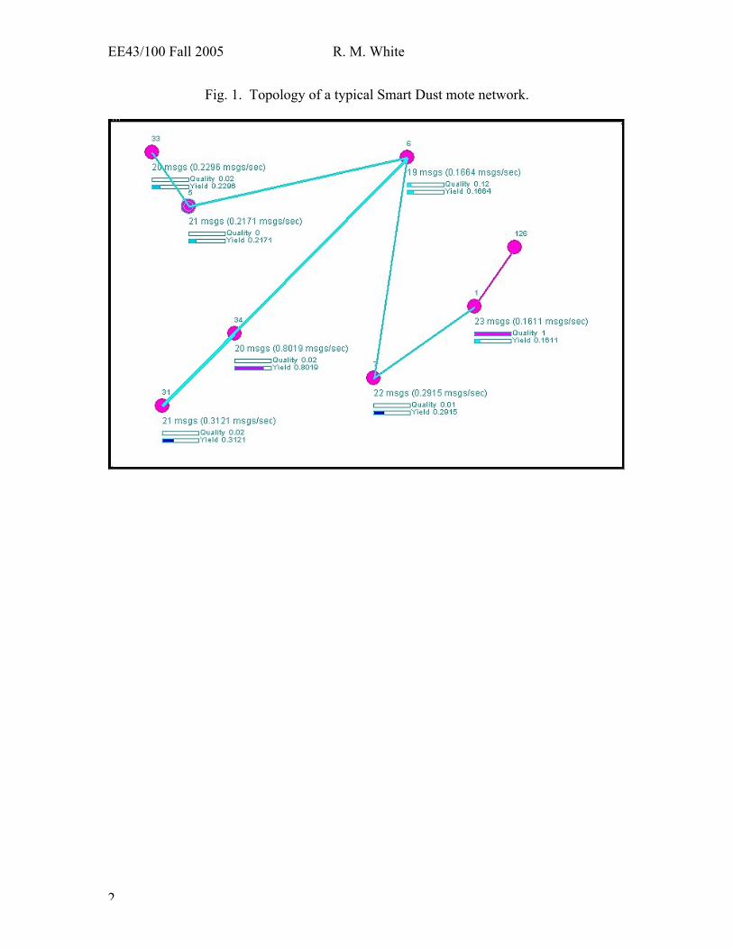
A computer software operating system – TinyOS – was developed in Berkeley’sComputer Science Division to control mote operation. When wireless motes are firstdispersed in an area – a room, a hallway, a building, or in a meadow – they autonomouslyattempt to set up a network along which they can send information from one mote toanother. Somewhere, one mote is plugged into a special printed circuit board (PCB) thatis connected to the serial port of a computer, such as a laptop. This board is known as a“base station”; its function is to collect the data provided to it by the assembly of motes.The topology of a typical Smart Dust mote network is shown in Fig. 1 below.
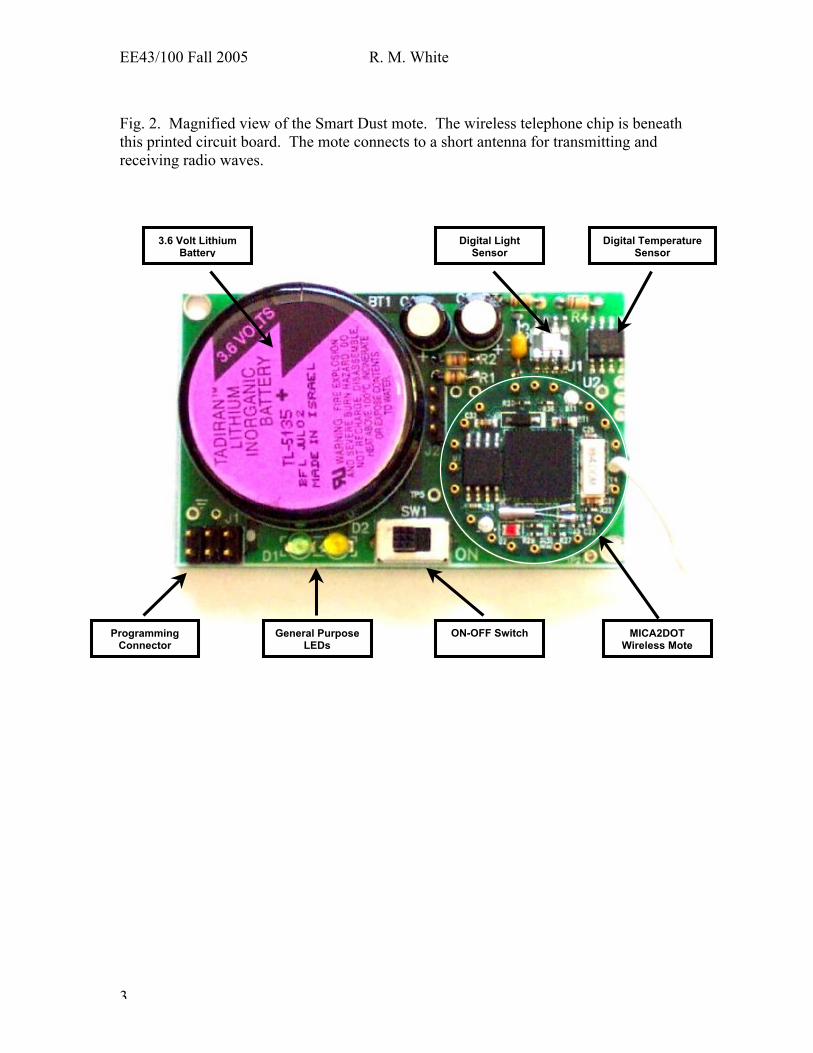
Fig. 2 shows a magnified view of one of the Smart Dust wireless sensor motes. Severalof its components are identified; beneath the printed circuit board that you see is anintegrated circuit like those used in portable telephones to drive an antenna connected tothe mote for transmitting the mote identification and measured sensor data to the basestation. These motes are made commercially by the Xbow Company (“cross-bow”),which you can reach at www.xbow.com .
EE43/100 Fall 2005 R. M. White
2
Fig. 1. Topology of a typical Smart Dust mote network.
EE43/100 Fall 2005 R. M. White
3
Fig. 2. Magnified view of the Smart Dust mote. The wireless telephone chip is beneaththis printed circuit board. The mote connects to a short antenna for transmitting andreceiving radio waves.
MICA2DOTWireless Mote
Digital TemperatureSensor
Digital LightSensor
3.6 Volt LithiumBattery
ON-OFF SwitchGeneral PurposeLEDs
ProgrammingConnector
EE43/100 Fall 2005 R. M. White
4
Each mote in the network has a unique identifier that it uses to preface each of itstransmissions. Every mote transmits any sensor data that it has taken, along withinformation from other motes sent to it for passing along to the base station. If the propersoftware has been installed in the base station’s computer, the network topology can bedisplayed on the base station’s monitor. One should thus be able to observe when motesare added to the network, or when they leave it. The sensor data taken by each motecould also be displayed, processed and stored by that computer.
3. Uses
The possible uses are limited only by the available sensors and by the range that thesemotes can achieve – tens to hundreds of meters with radio communication, up to miles incertain circumstances when the motes are outfitted for optical communication usinglasers.
The long list of sensed quantities that have been demonstrated includes: temperature,illumination, relative humidity, toxic gases, magnetic field, sound, acceleration, androtation rate. As examples of some of their uses, motes bearing on-board accelerometersare being installed on the Golden Gate bridge to measure the accelerations produced bywind and traffic, and burrowing birds on an Eastern seaboard island are being monitoredunobtrusively in their nests by motes that measure temperature and illumination, whichare surrogate indications of burrow occupancy and activity.
A key feature of the motes is their low cost. The motes that you will use costapproximately $100 each in a quantity order of a few hundreds, and it is predicted thatwithin a year or so the price might be as low as a few dollars. An important practicalrequirement is that the power required by any mote be kept low to prolong battery life;this means that the mote radios must be efficient, and that any sensors used must requirevery little power. Present motes require 10-20 mW for radio transmission and reception,and a number of sensors are available that are either passive (require no power source, anexample being a photodiode for measuring illumination) or have low powerrequirements.
3. References
Here are two web sites you can check out: robotics.eecs.berkeley.edu/~pister/SmartDust/ http://webs.cs.Berkeley.edu/tos/

EE43/100 Fall 2005 R. M. White
5
EE 43 Smart Dust Lab: Experiment Guide
Smart Dust Motes
The motes that you’ll use are contained in translucent plastic boxes that measure 1.5 x 2.5x 0.6 cubic inches. There is an insulated antenna (inside the plastic tubing – a sodastraw) attached to the box. You can turn on a mote by moving the black slide switch(visible through a hole in the box) with a small key or a pencil point; move the switchhandle in the direction of the attachment point of the antenna to turn it on. Be sure toturn the motes off when you’re finished with them to prevent battery drain.
Each pair of students will have available two motes in which stored TinyOS programsenable them to transmit and receive signals from similar motes, but be immune totransmissions from other motes. The boxes are marked S (send) or R (receive) to identifythe transmitter and receiver, respectively. (The motes inside those boxes have identicalhardware, but their software differs.) When a receiver is turned on, if there’s no sendingmote nearby that can communicate with it, nothing appears to happen. But when youturn on a transmitter, its red LED flashes periodically; a yellow and green LED also flash,acting as the readouts of a two-bit binary counter. The counts have no significance, butthey serve to show you that the mote is working properly. If you now turn on a receivingmote while the associated sender is still on, you should see the receiver’s lights flashingin synchrony with those of the transmitter.
When the motes are sensing real-world data – these motes can sense temperature andillumination – the measurements are transmitted over the wireless network to a basestation that is plugged into a serial port on a computer, permitting data storage anddisplay. Such a station should exist at one point in the lab.
Individual sensors
The original motes included analog sensors for temperature and illumination. We’ll nowdescribe how those sensors worked.
Temperature sensor – the thermistor
The analog temperature sensor on the mote is a black cube that is 1 mm on a side; it hassilvery electrodes on two opposing faces. This is a two-terminal semiconductor deviceknown as a thermistor because its resistance changes a lot when its temperature changes.When the temperature rises, the number of charge carriers in the thermistor increases,causing its electrical resistance to drop. (In common resistors, a temperature riseproduces a resistance rise because at higher temperatures the vibrations of the atoms ofthe resistor are more intense, which impedes the flow of electric charges through theresistor.)
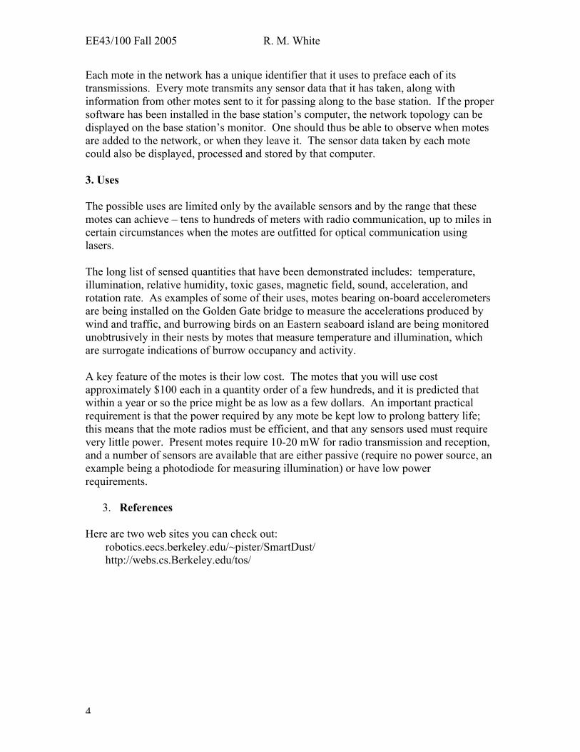
The thermistor you will test in the lab is not on the mote but rather is an individualJameco Thermistor Model NTC-103 (NTC = negative temperature coefficient, meaning
EE43/100 Fall 2005 R. M. White
6
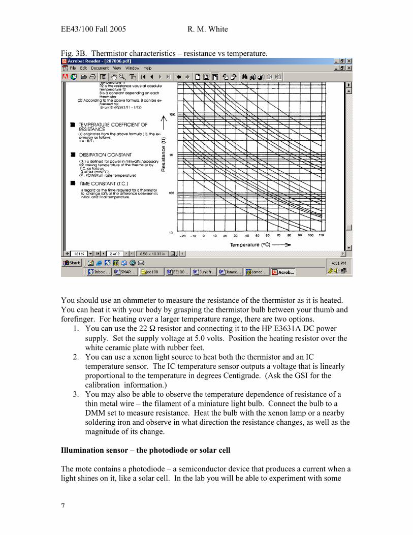
resistance goes down when temperature goes up). Several Jameco data sheets appear asFigs. 3A and 3B below. The characteristic curve for our thermistor in Fig. 3B should bethe one that has the value of 10 kΩ resistance at 25o C temperature (ask your GSI to besure).
Fig. 3A Some data on the Jameco thermistors.
EE43/100 Fall 2005 R. M. White
7
Fig. 3B. Thermistor characteristics – resistance vs temperature.
You should use an ohmmeter to measure the resistance of the thermistor as it is heated.You can heat it with your body by grasping the thermistor bulb between your thumb andforefinger. For heating over a larger temperature range, there are two options.
1. You can use the 22 Ω resistor and connecting it to the HP E3631A DC powersupply. Set the supply voltage at 5.0 volts. Position the heating resistor over thewhite ceramic plate with rubber feet.
2. You can use a xenon light source to heat both the thermistor and an ICtemperature sensor. The IC temperature sensor outputs a voltage that is linearlyproportional to the temperature in degrees Centigrade. (Ask the GSI for thecalibration information.)
3. You may also be able to observe the temperature dependence of resistance of athin metal wire – the filament of a miniature light bulb. Connect the bulb to aDMM set to measure resistance. Heat the bulb with the xenon lamp or a nearbysoldering iron and observe in what direction the resistance changes, as well as themagnitude of its change.
Illumination sensor – the photodiode or solar cell
The mote contains a photodiode – a semiconductor device that produces a current when alight shines on it, like a solar cell. In the lab you will be able to experiment with some
EE43/100 Fall 2005 R. M. White
8
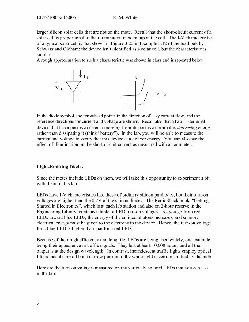
larger silicon solar cells that are not on the mote. Recall that the short-circuit current of asolar cell is proportional to the illumination incident upon the cell. The I-V characteristicof a typical solar cell is that shown in Figure 3.25 in Example 3.12 of the textbook bySchwarz and Oldham; the device isn’t identified as a solar cell, but the characteristic issimilar.A rough approximation to such a characteristic was shown in class and is repeated below. I D ID + V D - V D In the diode symbol, the arrowhead points in the direction of easy current flow, and the reference directions for current and voltage are shown. Recall also that a two -terminal device that has a positive current emerging from its positive terminal is delivering energyrather than dissipating it (think “battery”). In the lab, you will be able to measure thecurrent and voltage to verify that this device can deliver energy. You can also see theeffect of illumination on the short-circuit current as measured with an ammeter.
Light-Emitting Diodes
Since the motes include LEDs on them, we will take this opportunity to experiment a bitwith them in this lab.
LEDs have I-V characteristics like those of ordinary silicon pn-diodes, but their turn-onvoltages are higher than the 0.7V of the silicon diodes. The RadioShack book, “GettingStarted in Electronics”, which is at each lab station and also on 2-hour reserve in theEngineering Library, contains a table of LED turn-on voltages. As you go from redLEDs toward blue LEDs, the energy of the emitted photons increases, and so moreelectrical energy must be given to the electrons in the device. Hence, the turn-on voltagefor a blue LED is higher than that for a red LED.
Because of their high efficiency and long life, LEDs are being used widely, one examplebeing their appearance in traffic signals. They last at least 10,000 hours, and all theiroutput is at the design wavelength. In contrast, incandescent traffic lights employ opticalfilters that absorb all but a narrow portion of the white light spectrum emitted by the bulb.
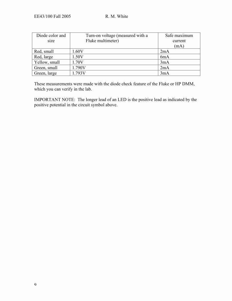
Here are the turn-on voltages measured on the variously colored LEDs that you can usein the lab:
EE43/100 Fall 2005 R. M. White
9
Diode color andsize
Turn-on voltage (measured with aFluke multimeter)
Safe maximumcurrent(mA)
Red, small 1.60V 2mARed, large 1.50V 6mAYellow, small 1.70V 3mAGreen, small 1.790V 2mAGreen, large 1.793V 3mA
These measurements were made with the diode check feature of the Fluke or HP DMM,which you can verify in the lab.
IMPORTANT NOTE: The longer lead of an LED is the positive lead as indicated by thepositive potential in the circuit symbol above.
EE43/100 Fall 2005 R. M. White
10
EE 43 Smart Dust Lab: PrelabName:___________________
TA: ___________________ Section:__________________
1. The antennas on the Smart Dust motes are 6-inch long pieces of insulated wire.(Only 5 inches sticks up straight on the motes you’ll use, but let’s ignore that detailhere.) To work efficiently, a typical radio antenna should be approximately one-quarter of a wavelength long. Recall from physics that for any kind of wave,including radio,
Wave frequency x Wavelength = Wave’s phase velocity Calculate the approximate frequency at which such a mote operates (reminder: the velocity of radio waves in free space is 3 x 10⁸ m/s).
2. List at least three applications you can think of for the Smart Dust wireless sensorplatforms in your field of study. (Be imaginative!)
3. For the small red LED listed in the table in the Guide, calculate the value of a seriescurrent-limiting resistor that will produce the maximum listed current for that LED,assuming that the source voltage is 6 volts. You may assume that the I-V characteristicfor the LED is the idealized characteristic – no current flows until the turn-on voltage isreached, at which point the characteristic becomes a vertical line.
EE43/100 Fall 2005 R. M. White
11
EE43 Smart Dust Lab ReportName:___________________Name:___________________
TA: __________Section:________
1. Testing your pair of motes
The motes have been programmed to respond to each other in pairs; you and your labpartner have been given one such pair. The sending mote is marked S, the receiving moteR.
Turn on the sending mote. Note which LEDs flash. Now turn on the receiving mote aswell. Observe and record any synchronous flashing of lights on the two motes. What arethe motes doing?
Measure the range of your pair of motes by taking them out in the hallway and movingapart until the synchronous behavior stops. This is the maximum range in thisenvironment. If weather permits, measure the range outdoors where it may be larger.Try mote operation around a corner, from inside a room to the hallway, etc Determinethe distance by pacing it off (a meter stick or tape measure is available if you don’t knowthe length of your stride). Try turning one mote until its antenna is perpendicular to theother mote’s antenna; does this make a difference in the range? Repeat while holdingone mote’s antenna close to the metal door of a hall locker. Does it make a differencewhether the S or the R mote’s antenna is placed next to the metal door while the other isheld in the middle of the hallway?
2. Demonstration of the frequency spectrum of your motes
The TA will use a “spectrum analyzer” to demonstrate how often a mote transmits, thecenter frequency of transmission, and some of the frequencies used in transmission. TheTA will explain what the equipment does and what its displays mean.
To do this demonstration, connect to the input of the spectrum analyzer a BNC cable thathas alligator clips on one end. Turn on a mote and place its antenna near the “hot”(center conductor) of the BNC cable. Adjust the range covered by the spectrum analyzerto sweep from roughly 100 to 1000 MHz. You should see an intermittent increase in theamplitude at one point on the trace, whose frequency corresponds to the frequency atwhich the mote is transmitting. Since mote communication occurs in bursts, thetransmission that you detect on the spectrum analyzer will also be intermittent. Measure
EE43/100 Fall 2005 R. M. White
12
the frequency of transmission and compare it with the value you predicted in Question 1of the Pre-Lab.
3. Laptop display of the Smart Dust network topology
When motes are dispersed in an area, they automatically set up a wireless network alongwhich data can be transferred to a mote that that is connected to the serial port of acomputer and has been configured as a base station. Figure 1 in the Theory part of thislab illustrated such a network. If possible, the TA will demonstrate a display of networktopology. As motes join or leave the network you should be able to see the networkchange.
4. Dynamic oscilloscope display of the temperature and/or illumination datacollected by a mote (note that this display may not be available in your lab owing toa lack of motes programmed to serve as a “base station” for the sensor network).
The mica2dot motes incorporate two standard sensors – a temperature sensor (analogthermistor, or possibly a digital temperature sensor) and an illumination sensor(photodiode). The packets sent over the mote network are composed of a header thatidentifies at least the sending mote, and then data from the sensors located on the mote. Ifthe network display is working, identify one of the motes in the room and note itsillumination data. Now cover that mote and observe the effect on its illumination data.Test the temperature sensing capability by putting your hand on the box holding themote. (Since there is air between the inside of the box and the thermistor on the mote,heating of the thermistor occurs mostly via radiation, so you may not be able to observe achange of temperature even after waiting for several minutes.)
5. Mote transmission under “difficult” conditions
Investigate the effect upon mote-to-mote transmission of putting one mote in a cardboardbox, a metal cabinet, and a non-functioning microwave oven to see whether itcommunicates through the closed door (which is designed to prevent the microwaves at2.45GHz from leaking out).Results:_________________________________________________________________________________________________________________________________________Note: it has been found experimentally that motes can communicate from inside a closedrefrigerator, suggesting a temperature measuring application in a computer-controlleddwelling.
6. Temperature sensing with thermistors
First, measure and record the resistance of your thermistor (round brown dot with twoleads) to determine the air temperature from the calibration plot of R vs. T in theExperiment Guide. Now measure and record the resistance corresponding to your body
EE43/100 Fall 2005 R. M. White
13
temperature by holding the thermistor between your thumb and forefinger. What bodytemperature does this indicate? Are your results reasonable?
Wire up a localized heater consisting of a 22 Ω resistor set on a white ceramic tile. Usingthe HP E3631A triple DC power supply to apply 5.0V to the heating resistor.
a. Put the thermistor in contact with the heating resistor for 30 seconds and recordthe magnitude and direction of the change of its resistance. What temperaturedoes the thermistor reach? (We’ll discuss semiconductors later in the course.)
b. Put the small lightbulb in contact with the heating resistor for 30 seconds. Bywhat percentage and in what direction did the resistance of its thin metallicfilament change?
7. Illumination sensor -- photodiode or solar cell
a. The single-crystal silicon solar cells in the transparent plastic boxes have a continuousback metallic contact to which one small insulated wire is soldered, and a comb-likemetallic contract on the other side that lets most of the incident light pass through into thecell.
First, record the number of your solar cell: _________
Use your DMM to determine the polarity of the voltage from the top, comb-like contactto the continuous back contact. Now switch your DMM to current mode and measure thecurrent flowing from the comb-like contact, through the ammeter – which acts like ashort-circuit – to the continuous back contact. If you need more light, use the smallhalogen* lamp, powered from the HP E3631A triple DC power supply; set the voltage at6.0V (the current will be about 0.6A. When you get ready to measure the solar cellcurrent and voltage you can set the lamp BRIEFLY on the solar cell package and make aQUICK measurement – 3 seconds should suffice, and not melt the plastic box containingthe solar cell.* There’s a halogen gas inside the bulb that helps keep the glass bulb free of metal thatevaporated from the hot filament
Record your data, including the direction of current flow at the contact that is positivewith respect to the other contact. From your investigation, what do you conclude aboutthe device as a deliverer or dissipater of energy?________________________________________________________________________________________________________________________________________________
To test whether the short-circuit current of a solar cell is proportional to the intensity ofthe light incident on the cell, illuminate the cell and measure its short-circuit current, thenput the piece of transparency material between the light and the cell and find the new
EE43/100 Fall 2005 R. M. White
14
short-circuit current. Check the proportionality (the relative transparency of each of thethree sections of the transparency should be marked on it).
Data and conclusions:________________________________________________________________________________________________________________________________________________
8. LED
Set the Fluke or HP DMM on its diode-check setting and apply the leads to an LED.NOTE 1: The AC-powered multimeters in the lab have a diode symbol setting but thatwon’t work for determining the turn-on voltage of a typical LED, though it does work fora regular pn-diode, which turns on at a lower voltage. NOTE 2: The + lead is the longerof the two leads. Does the LED light up? Record the LED type (small red, large red,etc.) and record the voltage displayed on the DMM. This is the voltage at which the LEDcurrent is about 0.40 mA, so this can be taken roughly as the LED turn-on voltage.
Wire up the small red LED with the series resistance you calculated in Question 3 of thePre-Lab and measure the current. By what percentage does it differ from your expectedcurrent?

EE43/100 Fall 2005 R. M. White
15
Appendix: Smart Dust Laptop Display – Illumination Level(This display may not be available in your lab session –
if it is you can see the structure of the packets sent by themotes )
Set-up: Smart Dust mote A sends wireless radio -frequency signal packet to mote B plugged in to “base station” that is connected to the serial port of the computer RF To serial Laptop Base station port
Mote A Mote B
Radio packet: Packet uses hexadecimal format; the packet contains a header thatidentifies the sending mote (Mote A), data from the light sensor, some unused time slots,and a cyclical redundancy check at the end:
7E 00 04 54 03 XX 01 00 00 … 00 01 00 [ ][ ][ ][ ] TinyOS header Unused CRC
Data from illumination sensor (TSL2550)
Hexadecimal number system: The base is 16, just as decimal numbers have a base 10. The hexadecimal numbersrepresent the decimal numbers from 0 to 15, as follows: Decimal number: 0 1 2 3 4 5 6 7 8 9 10 11 12 13 14 15 Hexadecimal equivalent: 0 1 2 3 4 5 6 7 8 9 A B C D E F
A hexadecimal number such as 7E means 7 x 161 + 14 x 160 = 7 x 16 + 14 x 1 = 126

EE43/100 Fall 2005 R. M. White
16
Revised 11.10.05RMW

![Lab6-JdbcTemplate Trinh Bay[1]](https://static.fdocuments.in/doc/165x107/577cc2ae1a28aba711945c02/lab6-jdbctemplate-trinh-bay1.jpg)