EE 4272Spring, 2003 Chapter 8 Multiplexing Frequency-Division Multiplexing Synchronous Time-Division...
24
EE 4272 Spring, 2003 Chapter 8 Multiplexing • Frequency-Division Multiplexing • Synchronous Time-Division Multiplexing • Statistical Time-Division Multiplexing • Asymmetric Digital Subscriber Line
-
Upload
stacy-bircher -
Category
Documents
-
view
249 -
download
8
Transcript of EE 4272Spring, 2003 Chapter 8 Multiplexing Frequency-Division Multiplexing Synchronous Time-Division...
EE 4272 Spring, 2003
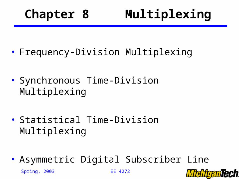
Chapter 8 Multiplexing
• Frequency-Division Multiplexing
• Synchronous Time-Division Multiplexing
• Statistical Time-Division Multiplexing
• Asymmetric Digital Subscriber Line

EE 4272 Spring, 2003
Multiplexing
B B
C C
A A
B
C
A
B
C
A
DMUXMUX
(a) (b)
Trunkgroup
The higher the data rate, the more cost-effective the trans. facility

EE 4272 Spring, 2003
Frequency Division Multiplexing
• A number of signals are carried simultaneously on the same medium.
• Each signal is modulated to a different carrier frequency• Useful bandwidth of medium should exceed required
bandwidth of channels • Carrier frequencies separated so signals do not overlap
(guard bands)• e.g. FM radio, CATV• Channel allocated even if no data

EE 4272 Spring, 2003
A CBf
Cf
Bf
Af
W
W
W
0
0
0
• Individual signals occupy W Hz
• The transmission channel bandwidth is divided into a number of frequency slots, each of which can accommodate the signal of an individual connection; Multiplexer assigns a frequency slot to each connections and uses modulation to place the signal of the connection in the appropriate slot
Frequency Division Multiplexing

EE 4272 Spring, 2003
FDM System
Transmitter:
1st Modulate -> Multiplex
-> 2nd Modulate
Receiver:
1st Demodulate->Demultiplex
->2nd Demodulate

EE 4272 Spring, 2003
FDM (Con’t)
• AT&T analog carrier system used a hierarchy of FDM schemes Group
-12 voice channels (4kHz each) = 48kHz -Range 60kHz to 108kHz
Supergroup - 60 channel - FDM of 5 group signals on carriers between
312kHz and 552kHz Mastergroup
-10 supergroups : 2.52MHZ bandwidth between 564KHz and 3084 kHz

EE 4272 Spring, 2003
Synchronous Time Division Multiplexing
• Data rate of medium exceeds data rate of digital signals to be transmitted
• Multiple digital signals interleaved in time• Interleaving can be at: bit level; blocks of bytes level; or
larger quantities level
• Time slots preassigned to sources and fixed• Time slots allocated even if no data• Time slots do not have to be evenly distributed amongst
sources -> TDM can handle source with different data rate.

EE 4272 Spring, 2003
Time Division Multiplexing
TDM
FDM
•With FDM, each channel continuously gets a fraction of the bandwidth.
•With TDM, each channel gets all of the bandwidth periodically during brief
intervals of time.

EE 4272 Spring, 2003
TDM System
Transmitter:Buffer->Multiplex ->Modulate
Receiver:Demodulate->Demultiplex -> Buffer

EE 4272 Spring, 2003
Synchronous TDM Link Control
• No headers and tailers for the TDM frame needed
• Data link control protocols are not needed for the overall TDM link, why? Flow control
Data rate of multiplexed line is fixed If one channel receiver can not receive data, the others
must carry on. This leaves empty slots Data link control protocol can be used on a per-channel
basis Error control
Errors are detected and handled by individual channel systems

EE 4272 Spring, 2003
Framing
• No flag or SYNC characters bracketing TDM frames
• Must provide frame synchronization mechanism
• Added digit framing One control bit added to each TDM frame
Looks like another channel - “control channel” Identifiable bit pattern used on control channel: e.g.
alternating 01010101…unlikely on a data channel To synchronize, a receiver compares incoming bits of
one frame position to the expected sync pattern

EE 4272 Spring, 2003
Pulse Stuffing
• Problem - Synchronizing various data sources• Clocks in different sources drifting• Data rates from different sources not related by simple
rational number• Solution - Pulse Stuffing
Outgoing data rate (excluding framing bits) higher than sum of incoming rates
Stuff extra dummy bits or pulses into each incoming signal until it matches local clock
Stuffed pulses inserted at fixed locations in the multiplexer frame format, and identified/removed at demultiplexer

EE 4272 Spring, 2003
Digital Carrier Systems: T-1 Carrier
• Digital Hierarchy of TDM• USA/Canada/Japan use this TDM structure of various
capacities • ITU-T use a similar (but different) system• US system based on DS-1 format• Multiplexes 24 channels• Each frame has 8 bits per channel plus one framing bit• 193 bits per frame

EE 4272 Spring, 2003
2
24
1
MUXMUX
1
2
24
24 b1 2 . . .b2322
frame
24 . . .
. . .
T-1 Carrier System
• A digital Telephone speech signal is obtained by sampling a speech waveform 8000 times/sec and by representing each sample with 8 bits.
• T-1 system uses a transmission frame that consists of 24 slots of 8 bits each. Each slot carries one PCM sample for a single connection.
• DS1: (1+24x8) bits/frame x 8000 frames/sec =1.544 Mbps

EE 4272 Spring, 2003
T-1 Carrier System (Con’t)
28
M13Multiplex
M23Multiplex
x7
PrimaryMultiplexe.g. DigitalSwitch24 chan PCM
M12Multiplex
x4
1
DS3 44.736 Mbps
DS1 1.544 Mbps DS2 6.312 Mbps DS3 44.736 Mbps
Digital Signal 1
Higher-level multiplexing achievable by interleaving bits from DS-1 inputs -> DS2 (6.312 Mbps), DS3 (44.736Mbps)
EE 4272 Spring, 2003
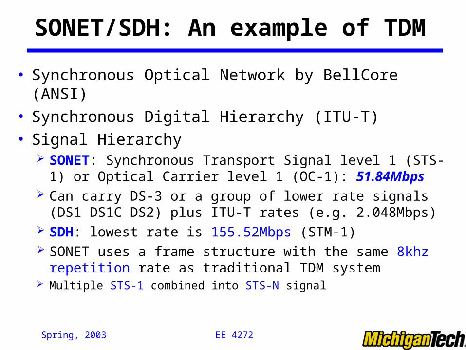
SONET/SDH: An example of TDM
• Synchronous Optical Network by BellCore (ANSI)• Synchronous Digital Hierarchy (ITU-T)• Signal Hierarchy
SONET: Synchronous Transport Signal level 1 (STS-1) or Optical Carrier level 1 (OC-1): 51.84Mbps
Can carry DS-3 or a group of lower rate signals (DS1 DS1C DS2) plus ITU-T rates (e.g. 2.048Mbps)
SDH: lowest rate is 155.52Mbps (STM-1) SONET uses a frame structure with the same 8khz repetition
rate as traditional TDM system Multiple STS-1 combined into STS-N signal
EE 4272 Spring, 2003
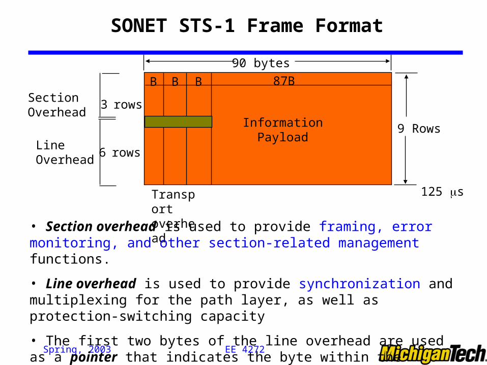
B BB 87B
InformationPayload
9 Rows
125 sTransportoverhead
90 bytes
SectionOverhead
3 rows
6 rowsLineOverhead
SONET STS-1 Frame Format
• Section overhead is used to provide framing, error monitoring, and other section-related management functions.
• Line overhead is used to provide synchronization and multiplexing for the path layer, as well as protection-switching capacity
• The first two bytes of the line overhead are used as a pointer that indicates the byte within the information payload where the SPE begins

EE 4272 Spring, 2003
Low-SpeedMappingFunction
MediumSpeed
MappingFunction
High-Speed
MappingFunction
DS3
44.736
DS1
DS2
CEPT-1
CEPT-4
139.264
ATM
150 Mbps
STS-1
STS-1
STS-1STS-1STS-1
STS-1STS-1STS-1
STS-3c
STS-3c
OC-n
Scrambler E/O
51.84 Mbps
High-Speed
MappingFunction
MuxSTS-n
SONET Multiplexing
EE 4272 Spring, 2003
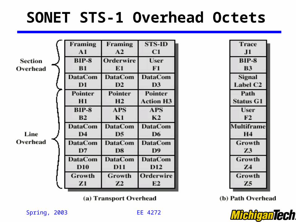
SONET STS-1 Overhead Octets

EE 4272 Spring, 2003
Statistical TDM
• In Synchronous TDM many slots are wasted
• Statistical TDM allocates time slots dynamically based on demand -> Sequence of data packets from multiple users does not have fixed pattern as FDM & TDM
• Data rate on output line lower than aggregate rates of input lines -> higher facility utilization; however, the need for “address” and “data length” causes big overhead
• May cause problems during peak periods Buffer inputs Keep buffer size limited to reduce delay
• Statistical TDM is the base for Packet Switching. While FDM and Synchronous TDM belong to Circuit Switching

EE 4272 Spring, 2003
Asymmetrical Digital Subscriber Line
• Explore the potential capacity of the installed twisted pair (0-1MHz)
• Asymmetric Digital Subscriber Line Greater capacity downstream than upstream
• Supported by Frequency division multiplexing Lowest 25kHz for voice: plain old telephone service
(POTS) The region above 25kHz is used for data transmission
Upstream: 64kbps to 640kbps Downstream: 1.536Mbps to 6.144Mbps

EE 4272 Spring, 2003
ADSL Channel Configuration

EE 4272 Spring, 2003
Discrete Multitone (DMT)
• ITU-T G.992.1 standard for ADSL uses DMT
• DMT divides available bandwidth into # of subchannels
• 4kHz for each subchannels
• The binary bits are distributed among the subchannel, each of which use QAM (using two copies of the carrier frequency, one shifted by 900)
• More bits feed to subchannels with high SNR, less bits to subchannels with poor SNR
• Current ADSL: 256 downstream subchannels (1.5 to 9Mbps).
EE 4272 Spring, 2003
xDSL
• High data rate DSL (HDSL): deliver T1 data (1.544Mbps) over two twisted pair lines -> replace T1 lines – 1.544 or 2.048 Mbps
• Single line DSL (SDSL): echo cancellation used
• Very high data rate DSL: 13 to 52 Mbps downstream