EDUSAT SESSION FOR COMPUTER NETWORKS-I (C S64) Topic ...
39
EDUSAT SESSION FOR COMPUTER NETWORKS-I (CS64) Date: 08.03.06/13.03.06/14.03.06/15.03.06/20.03.06/21.03.06/22.03.06/27.03.06 Session IV-XI Topic: Chapter 2 Local Area Networks Faculty: Anita Kanavalli MSRIT Notes LAN Protocols • Ethernet (IEEE 802.3 standard) • Token Bus (IEEE 802.4 LAN standard) • Token Ring (IEEE 802.5 LAN standard) and FDDI This chapter deals in detail about the above technologies. LAN structure • defines the structure of the network • contains both physical topology, which is the actual layout of the wire (media) [bus, star, ring, extended star, hierarchical, mesh ] and the logical topology, which defines how the media is accessed by the hosts [token passing] Examples The above figure shows how the hosts can be connected using any wiring media. This is called the bus topology. The circle depicts the nodes. They all share the same media. This is the simplest of all and easy to implement. Cost is less. Used in LAN. But only one communication can happen at a time. This is the ring topology the hosts are connected in a ring fashion and uses a special packet called token for the communication between the hosts. The ring maintenance is a important issue not as simple as bus to implement
Transcript of EDUSAT SESSION FOR COMPUTER NETWORKS-I (C S64) Topic ...

EDUSAT SESSION FOR COMPUTER NETWORKS-I (CS64)Date: 08.03.06/13.03.06/14.03.06/15.03.06/20.03.06/21.03.06/22.03.06/27.03.06Session IV-XITopic: Chapter 2 Local Area NetworksFaculty: Anita KanavalliMSRIT
Notes
LAN Protocols
• Ethernet (IEEE 802.3 standard)
• Token Bus (IEEE 802.4 LAN standard)
• Token Ring (IEEE 802.5 LAN standard) and FDDIThis chapter deals in detail about the above technologies.LAN structure
• defines the structure of the network• contains both physical topology, which is the actual layout of the wire (media)
[bus, star, ring, extended star, hierarchical, mesh] and the logical topology, whichdefines how the media is accessed by the hosts [token passing]
Examples
The above figure shows how the hosts can be connected using any wiring media. This iscalled the bus topology. The circle depicts the nodes. They all share the same media. Thisis the simplest of all and easy to implement. Cost is less. Used in LAN. But only onecommunication can happen at a time.
This is the ring topology the hosts are connected in a ring fashion and uses a specialpacket called token for the communication between the hosts. The ring maintenance is aimportant issue not as simple as bus to implement

EDUSAT SESSION FOR COMPUTER NETWORKS-I (CS64)Date: 08.03.06/13.03.06/14.03.06/15.03.06/20.03.06/21.03.06/22.03.06/27.03.06Session IV-XITopic: Chapter 2 Local Area NetworksFaculty: Anita KanavalliMSRIT
The above figure shows the star topology. There is a wiring hub to which the hosts areconnected. The data passes through the hub in the center. This is a very popular structureused in the LAN. The wiring hub can be a network device switch. The extended star alsois used. When all the nodes are connected to each other by the wiring media it becomesthe MESH topology.
The nodes are connected like a tree structure.
Satellite– nodes use an antenna to send and receive data– point-to-point from land based antenna to satellite– broadcast from the satellite to one or more ground stations
Hardware used in the hosts
NICsAdapters to connect devices to a networkPerform:
• framing• monitor the medium for transmissions• capture data from the medium and pass them to their hosts nodes for
processing• check errors• responsible for token passing
Also perform layer-1 function: convert bits to physical signals

EDUSAT SESSION FOR COMPUTER NETWORKS-I (CS64)Date: 08.03.06/13.03.06/14.03.06/15.03.06/20.03.06/21.03.06/22.03.06/27.03.06Session IV-XITopic: Chapter 2 Local Area NetworksFaculty: Anita KanavalliMSRIT
• NIC works in two modes:– General mode– Promiscuous mode
• In general mode, the Ethernet card of the computer will allow following types ofpackets:
– Packets send to the computer.– Broadcast Packet– Multicast packet and if computer is part of that multicast group.
• In promiscuous mode, the Ethernet card of the computer will allow all the packetsthat it receives.
Limitations of layer 1
• Cannot organize streams of bits.• Cannot name or identify computers.• Cannot communicate with the upper-level layers.• Cannot decide which computer will transmit binary data.
And hence the layer 2 provides the following functions
• Layer 2 uses framing to organize or group the bits.• Layer 2 uses an addressing process to identify computers.• Layer 2 uses Logical Link Control (LLC) to communicate with the upper-level
layers.• Layer 2 uses Media Access Control (MAC) to decide which computer will
transmit.
Various LAN standards
EDUSAT SESSION FOR COMPUTER NETWORKS-I (CS64)Date: 08.03.06/13.03.06/14.03.06/15.03.06/20.03.06/21.03.06/22.03.06/27.03.06Session IV-XITopic: Chapter 2 Local Area NetworksFaculty: Anita KanavalliMSRIT
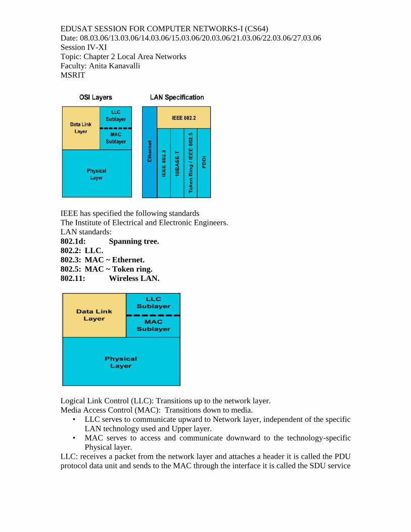
IEEE has specified the following standardsThe Institute of Electrical and Electronic Engineers.LAN standards:802.1d: Spanning tree.802.2: LLC.802.3: MAC ~ Ethernet.802.5: MAC ~ Token ring.802.11: Wireless LAN.
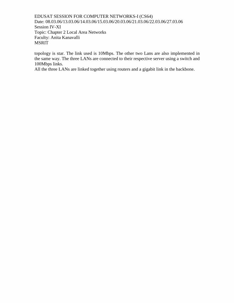
Logical Link Control (LLC): Transitions up to the network layer.Media Access Control (MAC): Transitions down to media.
• LLC serves to communicate upward to Network layer, independent of the specificLAN technology used and Upper layer.
• MAC serves to access and communicate downward to the technology-specificPhysical layer.
LLC: receives a packet from the network layer and attaches a header it is called the PDUprotocol data unit and sends to the MAC through the interface it is called the SDU service

EDUSAT SESSION FOR COMPUTER NETWORKS-I (CS64)Date: 08.03.06/13.03.06/14.03.06/15.03.06/20.03.06/21.03.06/22.03.06/27.03.06Session IV-XITopic: Chapter 2 Local Area NetworksFaculty: Anita KanavalliMSRIT
data unit and through the service access point SAP. The header will have DSAP d standsfor destination and SSAP s stands for the source.MAC: does the framing and the flow control.Concept of layer 21. Layer 2 uses framing to organize or group the data.2. Layer 2 uses a flat addressing convention.3. Layer 2 communicates with the upper-level layers through LLC.4. Layer 2 uses MAC to choose which computer will transmit binary data, from a groupin which all computers are trying to transmit at the same time.MAC Address
• Every computer has a unique way of identifying itself : MAC address or physicaladdress.
• The physical address is located on the Network Interface Card (NIC).• MAC addresses have no structure, and are considered flat address spaces.
It has 48 bits the first 24 bits are for the vendor and the next 24 bits are unique NICnumber.
• MAC addresses are sometimes referred to as burned-in addresses (BIAs) becausethey are burned into read-only memory (ROM) and are copied into random-accessmemory (RAM) when the NIC initializes.
• 0000.0c12.3456 or 00-00-0c-12-34-56MAC address are used by MAC layer to identify the destination.

EDUSAT SESSION FOR COMPUTER NETWORKS-I (CS64)Date: 08.03.06/13.03.06/14.03.06/15.03.06/20.03.06/21.03.06/22.03.06/27.03.06Session IV-XITopic: Chapter 2 Local Area NetworksFaculty: Anita KanavalliMSRIT
LAN systems• Based on LAN architecture just seen
The IEEE 802 Standards are an integral part of the architecture:• LAN’s• Ethernet (CSMA/CD)• Token Ring and FDDI• Wireless• ATM LAN’s
CSMA/CD• Architecture that combines standards, topologies and protocols.• Carriers Sense Multiple Access with Collision Detection is the most commonly
used medium access control technique• Developed by Xerox as part of Ethernet• Basis for IEEE 802.3• Most popular ~ 70%• With CSMA, collision occupies medium for duration of transmission• Stations listen whilst transmitting• If medium idle, transmit• If busy, listen for idle, then transmit• If collision detected, jam, then cease transmission• After jam, wait random time then start again
802.3 operation parameters• Slot Time = 2 x prog delay + safety margin
– 10Mbps coaxial cable, 2.5 Km it is 512 bits
• Times between retransmission attempts is a number R x slot time
• 0 to R < 2K, where K = min(N, backoff limit)CSMA/CD parameters
• Mini slot time: time duration that is at least as big as two propagation delay• Mini slot is basis for contention resolution• Backoff algorithm: The first retransmission time involves zero or one minislot
times, the second involves 0,1,2,3 minislot times and each additional slotretransmission extends the range the range by a factor of 2 until the maximumrange of 1210
• The average number of minislots in a contention period is approximately e=2.71therefore the fraction
• The average number of minislots in a contention period is approximately e=2.71therefore the fraction of time that the channel is busy transmitting frames is
L/R = 1L/R+tprop+2etprop 1+6.44a

EDUSAT SESSION FOR COMPUTER NETWORKS-I (CS64)Date: 08.03.06/13.03.06/14.03.06/15.03.06/20.03.06/21.03.06/22.03.06/27.03.06Session IV-XITopic: Chapter 2 Local Area NetworksFaculty: Anita KanavalliMSRIT
Where a=tprop R/LFrame format
There are three type of addresses unicast: permanently assigned to NIC multicast address:identify the group. Broadcast address: indicated by all 1s physical address. All stationsreceive the packet.FCS uses CRC(cyclic redundancy check ) for the error control. Pad bits are used to addsome bits if the length of the data frame is less because Ethernet requires minimum 512bytes.
Signaling rate(Mbps)
- Band -(Base orBroad)
Length (Meters)orCable Type
IEEE 802.3 are designated using the format above. For example 10BaseT means 10 is thesignalling rate in Mbps. Base is the Baseband. T stands for twisted pair.IEEE 802.3: 10Mbps specification (Ethernet)

EDUSAT SESSION FOR COMPUTER NETWORKS-I (CS64)Date: 08.03.06/13.03.06/14.03.06/15.03.06/20.03.06/21.03.06/22.03.06/27.03.06Session IV-XITopic: Chapter 2 Local Area NetworksFaculty: Anita KanavalliMSRIT
10Base-FBFiberBackbone
10Base-FLFiber Link
10Base-FPFiber Passive
Medium fiber fiber 850 nm fiber
Signaling Baseband - Manchester/ on-off
Topology Point-to-point
Point-to-pointor star
Star
maxsegmentlength
2000 m 2000 m 500 m
max. Nodes/segment
2 2 33
MaxDiameter
2500 m 2500 m 2500 m
The above table shows the summary of the Ethernet 10Mbps
Ethernet hub and switch topologies using twisted pair cabling

EDUSAT SESSION FOR COMPUTER NETWORKS-I (CS64)Date: 08.03.06/13.03.06/14.03.06/15.03.06/20.03.06/21.03.06/22.03.06/27.03.06Session IV-XITopic: Chapter 2 Local Area NetworksFaculty: Anita KanavalliMSRIT
The above figure shows the star topology and hub is used and it repeats the signal. Ifthere is a collision the hub sends the jam signal and the stations execute the backoffalgorithm. The stations are in the same collision domain.
The above figure shows that a switch or any other device connected where input portbuffers incoming the transmissions. The incoming frames are examined and transferred tothe appropriate output port.
10BaseT
• Provides three approaches to operating the LAN• First-stations are in collision domain• Second-hub operates as ethernet switch• Third- stations transmit in full duplex mode
Fast Ethernet100Base-TX 100Base-FX 100Base-T4
Medium Twisted pair fiber UTP
Signaling MLT-3 4B5B, NRZI 8B6T, NRZ
Topology Star Star Star
maxsegmentlength
100 m 412 m (half-duplex)2 km (full-duplex)
100 m

EDUSAT SESSION FOR COMPUTER NETWORKS-I (CS64)Date: 08.03.06/13.03.06/14.03.06/15.03.06/20.03.06/21.03.06/22.03.06/27.03.06Session IV-XITopic: Chapter 2 Local Area NetworksFaculty: Anita KanavalliMSRIT
networkdiameter
200 m 400 m 200 m
The above table summarizes the fast Ethernet technology.Giga bit Ethernet
• 1000Base-SX (short wavelength fiber)– Short wavelength (770-860 nm)– support duplex links of
• 220- 275 m using 62.5 m multimode fiber• 500- 550 m using 50 m multimode fiber
• 1000Base-LX (long wavelength fiber)– Long wavelength (1270-1355 nm)– support duplex links of
• 550 m using 62.5 m or 50 m multimode fiber• 5000 m using 9 m single-mode fiber
• 1000Base-CX (short haul copper)– supports 1-Gbps links within a single room or equipment rack– uses copper jumpers , special shielded twisted pair that spans no more
than 25 m• 1000Base-T
– uses 4 pairs of cat 5 UTP– support devices over a range of 100m
• Encoding scheme for Gigabit Ethernet is 8B/10BApplication of fast and gigabit Ethernet
The above figure shows the application of the fast and gigabit Ethernet technology. Thereare three departments and has the LANS the hosts are connected using a hub, the
EDUSAT SESSION FOR COMPUTER NETWORKS-I (CS64)Date: 08.03.06/13.03.06/14.03.06/15.03.06/20.03.06/21.03.06/22.03.06/27.03.06Session IV-XITopic: Chapter 2 Local Area NetworksFaculty: Anita KanavalliMSRIT
topology is star. The link used is 10Mbps. The other two Lans are also implemented inthe same way. The three LANs are connected to their respective server using a switch and100Mbps links.All the three LANs are linked together using routers and a gigabit link in the backbone.

EDUSAT SESSION FOR COMPUTER NETWORKS-I (CS64)Date: 08.03.06/13.03.06/14.03.06/15.03.06/20.03.06/21.03.06/22.03.06/27.03.06Session IV-XITopic: Chapter 2 Local Area NetworksFaculty: Anita KanavalliMSRIT
Token Ring 802.5• MAC protocol
– Small frame (token) circulates when idle– Station waits for token– Changes one bit in token to make it SOF for data frame– Append rest of data frame– Frame makes round trip and is absorbed by transmitting station– Station then inserts new token when transmission has finished and leading
edge of returning frame arrives– Under light loads, some inefficiency– Under heavy loads, round robin
Token ring format
• Tokens are 3 bytes in length and consists of a start delimiter, an access controlbyte, and an end delimiter.
• The start delimiter alerts each station to the arrival of a token, or data/commandframe. This field also includes signals that distinguish the byte from the rest of theframe by violating the encoding scheme used elsewhere in the frame.
• The access control byte contains the priority and reservation field, and a tokenand monitor bit. The token bit distinguishes a token from a data/command frame,and a monitor bit determines whether a frame is continuously circling the ring.The bit pattern for access control is PPP T M RRRPPP- indicate priority of token
T- token bit, T=0 -indicates token frame and T=1 indicates data frameM- monitor bit used by monitor to remove orphan frames.RRR- is used for reserving token priority Frame control byte has the pattern FF ZZZZZZ to distinguish between data
frame and control frame
Two types of token ring frames: Data/Commandand Token

EDUSAT SESSION FOR COMPUTER NETWORKS-I (CS64)Date: 08.03.06/13.03.06/14.03.06/15.03.06/20.03.06/21.03.06/22.03.06/27.03.06Session IV-XITopic: Chapter 2 Local Area NetworksFaculty: Anita KanavalliMSRIT
FF= 01 indicates data frameFF=00 indicates control frame then ZZZZZZ indicates type of control frame. SA and DA are as in 802.3 FCS - frame check sequence having CRC checksum Ending delimiter has last two bits to be I and E where
E- error bit, this bit is set if any station detects an error like line coding violation orframe check sequence error.
I- intermediate frame bit , it is set one to indicate last frame in the sequence of framesthat are transmitted. Frame status - has the pattern A C XX A C XX and it allows receiving station to
convey the data transfer status to sending station.A= 1 indicates destination address was recognized by receiving station.C=1 indicates that the frame was copied to receivers boffer properly
Token ring passing
• Token-passing networks move a small frame, called a token, around the network.• Possession of the token grants the right to transmit data.• If a node that receives a token has no information to send, it passes the token to
the next end station.• Each station can hold the token for a maximum period of time, depending on the
specific technology that has been implemented.• When a token is passed to a host that has information to transmit, the host seizes
the token and alters 1 bit of it. The token becomes a start-of-frame sequence.• Next, the station appends the information to transmit to the token and sends this
data to the next station on the ring. There is no token on the network while theinformation frame is circling the ring, unless the ring supports early token

EDUSAT SESSION FOR COMPUTER NETWORKS-I (CS64)Date: 08.03.06/13.03.06/14.03.06/15.03.06/20.03.06/21.03.06/22.03.06/27.03.06Session IV-XITopic: Chapter 2 Local Area NetworksFaculty: Anita KanavalliMSRIT
releases. Other stations on the ring cannot transmit at this time. They must waitfor the token to become available.
• Token Ring networks have no collisions. If early token release is supported, a newtoken can be released when the frame transmission has been completed.
• The information frame circulates around the ring until it reaches the intendeddestination station, which copies the information for processing. The informationframe continues around the ring until it reaches the sending station, where it isremoved. The sending station can verify whether the frame was received andcopied by the destination.
• Unlike CSMA/CD networks, such as Ethernet, token-passing networks aredeterministic. This means that you can calculate the maximum time that will passbefore any end station will be able to transmit.
• This feature, and several reliability features, makes Token Ring networks ideal forapplications where any delay must be predictable, and robust network operation isimportant. Factory automation environments are examples of predictable robustnetwork operations.
• Token Ring networks use a sophisticated priority system that permits certain user-designated, high-priority stations to use the network more frequently. Token Ringframes have two fields that control priority - the priority field and the reservationfield.
• Only stations with a priority equal to, or higher than, the priority value containedin a token can seize that token.
• Once the token has been seized and changed to an information frame, onlystations with a priority value higher than that of the transmitting station canreserve the token for the next network pass.
• The next token generated includes the higher priority of the reserving station.Stations that raise a token's priority level must reinstate the previous priority whentheir transmission has been completed.
• Token Ring networks use several mechanisms for detecting and compensating fornetwork faults.
• One mechanism is to select one station in the Token Ring network to be the activemonitor. This station acts as a centralized source of timing information for otherring stations and performs a variety of ring maintenance functions. The activemonitor station can potentially be any station.
• One of this station’s functions is to remove continuously circulating frames fromthe ring. When a sending device fails, its frame may continue to circle the ringand prevent other stations from transmitting their frames, which can lock up thenetwork. The active monitor can detect these frames, remove them from the ring,and generate a new token.
• The IBM Token Ring network's physical star topology also contributes to overallnetwork reliability. Active MSAUs (multi-station access units) can see all

EDUSAT SESSION FOR COMPUTER NETWORKS-I (CS64)Date: 08.03.06/13.03.06/14.03.06/15.03.06/20.03.06/21.03.06/22.03.06/27.03.06Session IV-XITopic: Chapter 2 Local Area NetworksFaculty: Anita KanavalliMSRIT
information in a Token Ring network enabling them to check for problems and toselectively remove stations when necessary.
• Beaconing - a Token Ring formula - detects and tries to repair network faults.When a station detects a serious problem with the network (e.g. a cable break) itsends a beacon frame. The beacon frame defines a failure domain. A failuredomain includes the station that is reporting the failure, its nearest activeupstream neighbor (NAUN), and everything in between.
• Beaconing initiates a process called autoreconfiguration, where nodes within thefailure domain automatically perform diagnostics. This is an attempt toreconfigure the network around the failed areas.
• Physically, MSAUs can accomplish this through electrical reconfiguration.• The 4/16 Mbps Token Ring networks use differential Manchester encoding.• Token Ring uses the differential Manchester encoding method to encode clock
and data bit information into bit symbols.Token Ring network stations are directly connected to MSAUs and can be wired togetherto form one large ring.Patch cables connect MSAUs to other MSAUs that are adjacent.Lobe cables connect MSAUs to stations. MSAUs include bypass relays for removingstations from the ring.
FDDI
Fiber Distributed Data Interface (FDDI) came about because system managers becameconcerned with network reliability issues as mission-critical applications wereimplemented on high-speed networks.FDDI is frequently used as a backbone technology and to connect high-speed computersin a LAN.FDDI has four specifications:MediaAccessControl—defineshowthemediumis accessedframe formattoken handlingaddressing algorithm forcalculating a cyclic redundancy check and error-recovery mechanismsFDDI has four specifications:

EDUSAT SESSION FOR COMPUTER NETWORKS-I (CS64)Date: 08.03.06/13.03.06/14.03.06/15.03.06/20.03.06/21.03.06/22.03.06/27.03.06Session IV-XITopic: Chapter 2 Local Area NetworksFaculty: Anita KanavalliMSRIT
Physical Layer Protocol—defines data encoding/decoding proceduresclocking requirements framingFDDI has four specifications:Physical Layer Medium—defines the characteristics of the transmission medium fiberoptic link power levels bit error rates optical components connectorsFDDI has four specifications:Station Management—defines the FDDI station configuration ring configuration ringcontrol features stationinsertion and removal initialization fault isolation and recoveryRecovery collection of statisticsUnlike CSMA/CD networks, such as Ethernet, token-passing networks are deterministic--you can calculate the maximum time that will pass before any end station will be able totransmit. FDDI's dual ring makes FDDI very reliable.FDDI supports real-time allocationof network bandwidth, making it ideal for a variety ofdifferent application types. FDDI provides this support by defining two types of traffic –synchronous and asynchronous.
• Synchronous traffic can consume a portion of the 100 Mbps total bandwidth of anFDDI network, while asynchronous traffic can consume the rest.
• Synchronous bandwidth is allocated to those stations requiring continuoustransmission capability. This is useful for transmitting voice and videoinformation.
• The remaining bandwidth is used for asynchronous transmissions.• The FDDI SMT specification defines a distributed bidding scheme to allocate
FDDI bandwidth• Asynchronous bandwidth is allocated using an eight-level priority scheme. Each
station is assigned an asynchronous priority level.• FDDI also permits extended dialogues, in which stations may temporarily use all
asynchronous bandwidth.• The FDDI priority mechanism can lock out stations that cannot use synchronous
bandwidth and that have too low an asynchronous priority.• FDDI uses an encoding scheme called 4B/5B. Every 4 bits of data are sent as a 5
bit code. The signal sources in FDDI transceivers are LEDs or lasers.• FDDI specifies a 100 Mbps, token-passing, dual-ring LAN that uses a fiber-optic
transmission medium.• It defines the physical layer and media access portion of the data link layer,
which is similar to IEEE 802.3 and IEEE 802.5 in its relationship to the OSIModel.
• Although it operates at faster speeds, FDDI is similar to Token Ring.• The two networks share a few features, such as topology (ring) and media access
technique (token-passing). A characteristic of FDDI is its use of optical fiber as atransmission medium.
• Optical fiber is exploding in popularity as a networking medium, being installedat a rate of 4000 miles per day in the United States.

EDUSAT SESSION FOR COMPUTER NETWORKS-I (CS64)Date: 08.03.06/13.03.06/14.03.06/15.03.06/20.03.06/21.03.06/22.03.06/27.03.06Session IV-XITopic: Chapter 2 Local Area NetworksFaculty: Anita KanavalliMSRIT
• Single-mode fiber is capable of higher bandwidth and greater cable run distancesthan multi-mode fiber.
• Because of these characteristics, single-mode fiber is often used for inter-building connectivity while multi-mode fiber is often used for intra-buildingconnectivity.
• Multi-mode fiber uses LEDs as the light-generating devices while single-modefiber generally uses lasers.
• FDDI specifies the use of dual rings for physical connections. Traffic on eachring travels in opposite directions.
• Physically, the rings consist of two or more point-to-point connections betweenadjacent stations.
• One of the two FDDI rings is called the primary ring; the other is called thesecondary ring.
• The primary ring is used for data transmission; the secondary ring is generallyused as a back up.
• Class B, or single-attachment stations (SAS), attach to one ring; Class A, or dualattachment stations (DAS), attach to both rings.
• SASs are attached to the primary ring through a concentrator, which providesconnections for multiple SASs. The concentrator ensures that a failure, or powerdown, of any given SAS, does not interrupt the ring. This is Particularly usefulwhen PCs, or similar devices that frequently power on and off, connect to thering.
• Each FDDI DAS has two ports, designated A and B. These ports connect thestation to dual FDDI ring; therefore each port provides a connection for bothprimary and secondary rings.
Example Ring Latency and Token reinsertion
• Let there be M stations• b bits delay in stations• The delay in interface is Mb bits• typically b=2.5• d total ring length• additional delay is d/v or dR/v v-delay in medium• v=2*108 m/sec• therefore it is 5microsec to travel 1 kms• ring latency is defined as the time that it takes for a bit to travel around ring is
given by• T’=d/v+Mb/R and T’R= dR/v+Mb bits• Example• Let R=4Mbps M=20 stations separated by 100m b=2.5• Latency= 20*100*4*106 /2*108 +20*2.5=90 bits

EDUSAT SESSION FOR COMPUTER NETWORKS-I (CS64)Date: 08.03.06/13.03.06/14.03.06/15.03.06/20.03.06/21.03.06/22.03.06/27.03.06Session IV-XITopic: Chapter 2 Local Area NetworksFaculty: Anita KanavalliMSRIT
• IEEE 802.5-After the last bit arrives the token is inserted• IBM token ring-after the header bit arrives the token is inserted• IEEE 802.5 and IBM token ring 26Mbps- after last bit transmitted the token is
inserted• Conclusion-improves efficiency in case of the third case.
EDUSAT SESSION FOR COMPUTER NETWORKS-I (CS64)Date: 08.03.06/13.03.06/14.03.06/15.03.06/20.03.06/21.03.06/22.03.06/27.03.06Session IV-XITopic: Chapter 2 Local Area NetworksFaculty: Anita KanavalliMSRIT
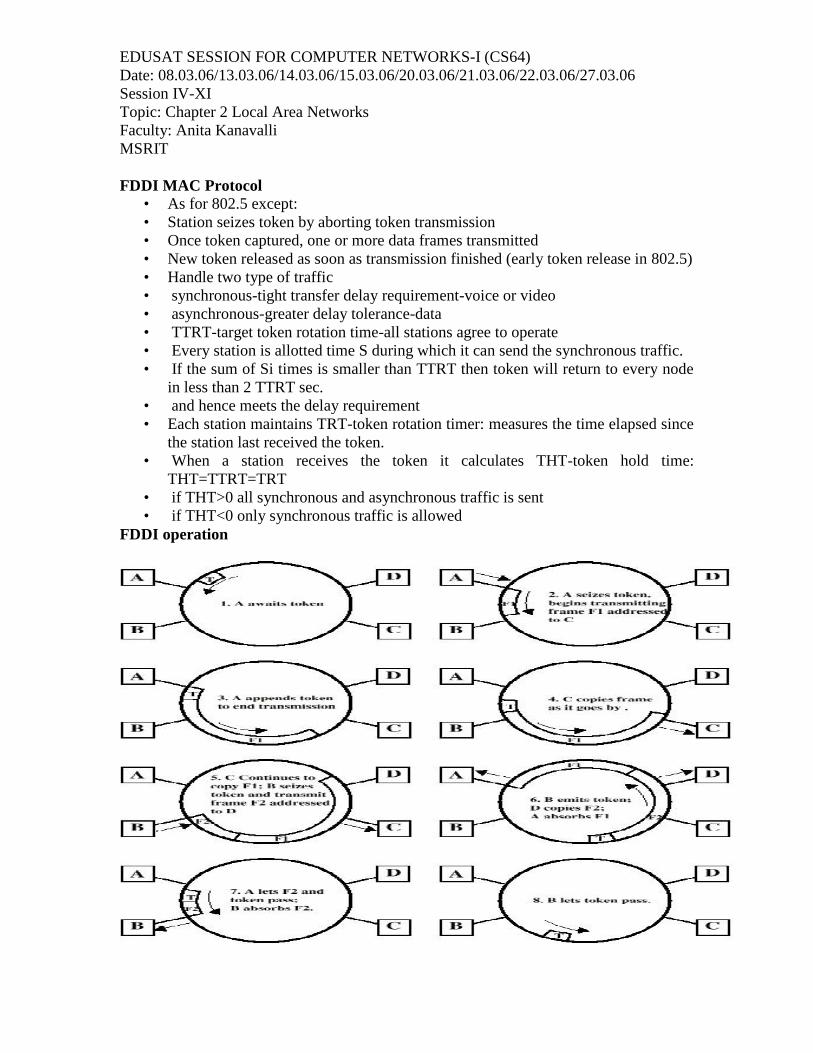
FDDI MAC Protocol• As for 802.5 except:• Station seizes token by aborting token transmission• Once token captured, one or more data frames transmitted• New token released as soon as transmission finished (early token release in 802.5)• Handle two type of traffic• synchronous-tight transfer delay requirement-voice or video• asynchronous-greater delay tolerance-data• TTRT-target token rotation time-all stations agree to operate• Every station is allotted time S during which it can send the synchronous traffic.• If the sum of Si times is smaller than TTRT then token will return to every node
in less than 2 TTRT sec.• and hence meets the delay requirement• Each station maintains TRT-token rotation timer: measures the time elapsed since
the station last received the token.• When a station receives the token it calculates THT-token hold time:
THT=TTRT=TRT• if THT>0 all synchronous and asynchronous traffic is sent• if THT<0 only synchronous traffic is allowed
FDDI operation

EDUSAT SESSION FOR COMPUTER NETWORKS-I (CS64)Date: 08.03.06/13.03.06/14.03.06/15.03.06/20.03.06/21.03.06/22.03.06/27.03.06Session IV-XITopic: Chapter 2 Local Area NetworksFaculty: Anita KanavalliMSRIT
Wireless LAN 802.11
Protocol stack Frame structure MAC protocol services
The above figure shows the protocol stack of the wireless LANWhy not Ethernet ?Several reasons as to why it cannot be used
• difficult to detect collisions• not controlled as the wired ones• Hidden station problem

EDUSAT SESSION FOR COMPUTER NETWORKS-I (CS64)Date: 08.03.06/13.03.06/14.03.06/15.03.06/20.03.06/21.03.06/22.03.06/27.03.06Session IV-XITopic: Chapter 2 Local Area NetworksFaculty: Anita KanavalliMSRIT
The above figure shows the hidden station problemInfrastructure networks
• Basic Service Set (BSS) contains:– wireless hosts– access point (AP): base station
• BSS’s combined to form distribution system (DS) to form a extended service setESS
• ESS provide gateway access for wireless users into wired network. This access isdone through a device called portal
The figure shows the distributed system.Different services associated with the wireless lan are
• Association• Disassociation• Reassociation• Distribution• Integration
Intracell services• Authentication• Deauthentication

EDUSAT SESSION FOR COMPUTER NETWORKS-I (CS64)Date: 08.03.06/13.03.06/14.03.06/15.03.06/20.03.06/21.03.06/22.03.06/27.03.06Session IV-XITopic: Chapter 2 Local Area NetworksFaculty: Anita KanavalliMSRIT
• Privacy• Data Delivery
Adhoc networks• Ad hoc network: IEEE 802.11 stations can dynamically form network without AP• Applications:
– “laptop” meeting in conference room, car– interconnection of “personal” devices– battlefield
Frame structure
There are three types of frames

EDUSAT SESSION FOR COMPUTER NETWORKS-I (CS64)Date: 08.03.06/13.03.06/14.03.06/15.03.06/20.03.06/21.03.06/22.03.06/27.03.06Session IV-XITopic: Chapter 2 Local Area NetworksFaculty: Anita KanavalliMSRIT
Management frame-used for station association and dissociation with the APtiming and synchronization and authentication and deauthentication
Control frame-used for handshaking and for positive ack Data frame-for transmission of data MAC header provides information on frame control, duration, addressing and
sequence control MAC sublayer is responsible for channel access procedures, pdu addressing
,formatting, fragmentation and reassembly of MSDUs supports security services through authentication and privacy mechanisms management services support roaming within and ESS and assist stations in
power management. The figure on the next figure shows the MAC architecture
It is defined using the coordination functionsDCF offers the contention service where the stations have to contend to use the channel.Uses CSMA/CAThe basic operation is as follows

EDUSAT SESSION FOR COMPUTER NETWORKS-I (CS64)Date: 08.03.06/13.03.06/14.03.06/15.03.06/20.03.06/21.03.06/22.03.06/27.03.06Session IV-XITopic: Chapter 2 Local Area NetworksFaculty: Anita KanavalliMSRIT
• 802.11 CSMA: sender• - if sense channel idle for DISF sec.• then transmit entire frame (no collision detection)• -if sense channel busy then binary backoff
• 802.11 CSMA receiver:• if received OK• return ACK after SIFS
• CSMA/CA: explicit channel reservation– sender: send short RTS: request to send

EDUSAT SESSION FOR COMPUTER NETWORKS-I (CS64)Date: 08.03.06/13.03.06/14.03.06/15.03.06/20.03.06/21.03.06/22.03.06/27.03.06Session IV-XITopic: Chapter 2 Local Area NetworksFaculty: Anita KanavalliMSRIT
– receiver: reply with short CTS: clear to send• CTS reserves channel for sender, notifying (possibly hidden) stations• avoid hidden station collisions• RTS and CTS short:
– collisions less likely, of shorter duration– end result similar to collision detection
• IEEE 802.11 alows:– CSMA– CSMA/CA: reservations– polling from AP
Physical layer
It is defined to operate with its MAC layerThere are three types of frame format. Frequency hopping spread spectrum Direct sequence spread spectrum Infrared frame format

EDUSAT SESSION FOR COMPUTER NETWORKS-I (CS64)Date: 08.03.06/13.03.06/14.03.06/15.03.06/20.03.06/21.03.06/22.03.06/27.03.06Session IV-XITopic: Chapter 2 Local Area NetworksFaculty: Anita KanavalliMSRIT
LAN bridgesLimitations of hubs
• single collision domain results in no increase in max throughput– multi-tier throughput same as single segment throughput
• individual LAN restrictions pose limits on number of nodes in same collisiondomain and on total allowed geographical coverage
• cannot connect different Ethernet types (e.g., 10BaseT and 100baseT)Bridges
• A network component connecting LAN’s together.• Operates only in the data link layer, thus is can handle any network protocol used.• May be used
– to divide the large expensive and hard to manage network into smallerLAN’s.
– split networks that became loaded over time.– to handle larger distances.– to block some traffic leaking outside the network.
Link Layer devices: operate on Ethernet frames, examining frame header and selectivelyforwarding frame based on its destinationBridge isolates collision domains since it buffers framesWhen frame is to be forwarded on segment, bridge uses CSMA/CD to access segmentand transmit
• Bridge advantages:– Isolates collision domains resulting in higher total max throughput, and
does not limit the number of nodes nor geographical coverage
– Can connect different type Ethernet since it is a store and forward device
– Transparent: no need for any change to hosts LAN adapters
• bridges filter packets– same-LAN -segment frames not forwarded onto other LAN segments
• forwarding:– how to know which LAN segment on which to forward frame?– looks like a routing problem (more shortly!)
• Reasons for bridges– Limited number of stations on a LAN segment or ring– Limited distance for executing CSMA / CD algorithm or distance one
wants a token traveling on a ring– Limited traffic on a single LAN: available bandwidth must be shared by
all stations• Interconnecting networks

EDUSAT SESSION FOR COMPUTER NETWORKS-I (CS64)Date: 08.03.06/13.03.06/14.03.06/15.03.06/20.03.06/21.03.06/22.03.06/27.03.06Session IV-XITopic: Chapter 2 Local Area NetworksFaculty: Anita KanavalliMSRIT
– Networks connected at the physical layer are connected by a repeater– Networks connected at the MAC or link layer are connected by bridges– Networks connected at the network layer are connected by routers– Higher layer interconnection devices that perhaps execute additional
functions such as protocol conversion are often called gateways• Bridges
– Devices for gluing together LANs so that packets can be forwarded fromone LAN to the other
A bridged LAN
Interconnection by bridge

EDUSAT SESSION FOR COMPUTER NETWORKS-I (CS64)Date: 08.03.06/13.03.06/14.03.06/15.03.06/20.03.06/21.03.06/22.03.06/27.03.06Session IV-XITopic: Chapter 2 Local Area NetworksFaculty: Anita KanavalliMSRIT
• The no frills bridge : simply transmit all traffic from one LAN segment onto allthe other segments
– Advantages: two stations can be transmitting at the same time. Bridgewill buffer a packet until it can transmit on a LAN
– Disadvantages: total bandwidth still that can be safely utilized is still theminimum bandwidth of each LAN segment
• Keeping a database of all stations on each LAN segment– Manually enter addresses in such a database– Partition addresses into ranges on each LAN
• Eg. LAN 1 has 1-50, LAN 2 has 51-100, LAN 3 has 101-150– Have the MAC address be hierarchically divided into a LAN address and a
station address (like the IP address)– None of these solutions are really used
• Better solution: the transparent learning bridge– Learn on which segment a station resides– Transmit a packet only onto the correct segment
• bridges learn which hosts can be reached through which interfaces: maintainfiltering tables
– when frame received, bridge “learns” location of sender: incoming LANsegment
– records sender location in filtering table• filtering table entry:
– (Node LAN Address, Bridge Interface, Time Stamp)– stale entries in Filtering Table dropped (TTL can be 60 minutes)
• filtering procedure:– if destination is on LAN on which frame was received
• then drop the frame• else { lookup filtering table• if entry found for destination
• then forward the frame on interface indicated;• else flood; /* forward on all but the interface on
which the frame arrived*/• }
Transparent bridge• Main idea: A bridge should easily connect any set of LAN’s together and make
the connection transparent to the stations.• No maintenance, software upgrade and routing table upload should be necessary.• The bridge listens to both network at all times.• Any frame received is buffered.
EDUSAT SESSION FOR COMPUTER NETWORKS-I (CS64)Date: 08.03.06/13.03.06/14.03.06/15.03.06/20.03.06/21.03.06/22.03.06/27.03.06Session IV-XITopic: Chapter 2 Local Area NetworksFaculty: Anita KanavalliMSRIT
• Next the bridge should be able to decide if the frame was addressed to a station inthe same network. If not, it should select the proper LAN and broadcast the framethere.
• Backward Learning:• The bridge keeps a table containing hashed (address, network) entry pairs.• The bridge accepts any frame, if the destination address is in the table then
the frame is forwarded to the proper network, otherwise the frame isbroadcast onto all networks (except the one its coming from).
• For each incoming frame the bridge also read the source address andupdates the hash table by inserting the source address and the network idinto the tables.
• Entries in the table can live for a certain time, and if there is no packettraffic from or to that an address the entry is removed from the table.
• Maintain a forwarding database or cache of station MAC addresses and the bridgeport that the stations are on
• Promiscuously listen to packets arriving on any port• For each packet arriving at the bridge:
• Store the stations source address and arriving port in the cache (if an entryalready exists for an address update if different)
– determine if the destination address is in the cache• If entry then forward only on the appropriate port unless the port is
the same as the arrival port• If no such entry then forward packet on all segments except the
one the packet was received on.– Age each entry in the cache and delete after an appropriate time
Spanning tree bridge• for increased reliability, desirable to have redundant, alternate paths from source
to dest• with multiple simultaneous paths, cycles result - bridges may multiply and
forward frame forever• solution: organize bridges in a spanning tree by disabling subset of interfaces

EDUSAT SESSION FOR COMPUTER NETWORKS-I (CS64)Date: 08.03.06/13.03.06/14.03.06/15.03.06/20.03.06/21.03.06/22.03.06/27.03.06Session IV-XITopic: Chapter 2 Local Area NetworksFaculty: Anita KanavalliMSRIT
• As the system grows a complex graph of many networks and many bridgesappear.
• Frames may loop through networks!• Bridges communicate to build dynamic spanning tree graph, showing the
topology of the network.• Spanning tree graphs avoid loops.
• First the bridge with the smallest serial number becomes the root of the tree.• Next the tree is constructed. LAN’s are placed on the nodes, and bridges are
placed on the vertices.• If a LAN or bridge is no longer present the tree is updated.• All networks are on the tree but to prevent loops some of the bridges are left off
the graph. This makes the graph a tree• Elect a single bridge among all bridges as the root bridge. The algorithm will
select the root bridge as the one with the lowest bridge id.• Each bridge (except root) determines the least cost path (shortest path with respect
to some metric, say hops) from itself to the root bridge through each of its ports.The port with least cost is the root port for that bridge. In case of ties use thesmallest port id.
• Elect a designated bridge for each LAN from the bridges directly connecting tothat LAN. The designated bride is the one closest to the root bridge. In case of
Disabled

EDUSAT SESSION FOR COMPUTER NETWORKS-I (CS64)Date: 08.03.06/13.03.06/14.03.06/15.03.06/20.03.06/21.03.06/22.03.06/27.03.06Session IV-XITopic: Chapter 2 Local Area NetworksFaculty: Anita KanavalliMSRIT
ties it is the one with the lowest bridge id. The port that connects the designatedbridge and the LAN is the designated port for that LAN.
• Ports in the spanning tree are all root ports and designated ports. Other ports arein the blocking state.
• Data traffic is forwarded to and received from ports in the spanning tree only.ExampleSample topology
using spanning tree

EDUSAT SESSION FOR COMPUTER NETWORKS-I (CS64)Date: 08.03.06/13.03.06/14.03.06/15.03.06/20.03.06/21.03.06/22.03.06/27.03.06Session IV-XITopic: Chapter 2 Local Area NetworksFaculty: Anita KanavalliMSRIT
How algorithm works• Bridges exchange bridge protocol data units (BPDUs). These have configuration
messages consisting of:– Root ID, bridge assumed by sending bridge to be the root– Transmitting bridge ID– Cost of least cost path to the root of which the transmitting bridge is aware
• When a bridge receives a configuration message from a neighbor bridge, itcompares this with what it would transmit over that port. Note that it will add thecost to the received message before comparison. It saves the best configurationmessage received for each port. If the saved configuration is better than what itwould transmit it stops transmitting BPDUs over that
• All bridges start by transmitting on all ports:– Root id is own id– Transmitting id is own id– Cost is 0– (Port id of port)– Which is a better message?
First compare root ID, lower is betterIf tie, next compare costs, lower is betterIf tie, next compare transmitting ID, lower is betterIf still tie, port id is tie breakerEventually only the root bridge is transmitting.
Source routing bridges• CSMA/CD community preferred to use transparent bridges due to their
simplicity.• The Token Ring community, however, preferred source routing bridges.• In source routing, the sending station knows whether the destination is on the
same network. If it is not, the sender sets the higher destination address bit to 1and includes the exact path to the frame header.
• The path is a sequence of alternating bridge and LAN addresses (4bits/12bits).• This requires that each machine know the topology and can construct a path to
any receiver.• Instead, the sender first broadcasts a discovery frame asking the receiver to signal
himself. In the return trip bridges record their addresses in the frame header andthe path is formed.
• Problem: Too many frame loose in the network.

EDUSAT SESSION FOR COMPUTER NETWORKS-I (CS64)Date: 08.03.06/13.03.06/14.03.06/15.03.06/20.03.06/21.03.06/22.03.06/27.03.06Session IV-XITopic: Chapter 2 Local Area NetworksFaculty: Anita KanavalliMSRIT
Frame format
The routing information field is inserted only if the stations are on different LANs if this field is present, then I/G bit in src addr field is 1 otherwise it is 0 The routing control field defines: type of frame, length of routing information
field and direction of the route designator field(L to R or R to L)Route discovery
First the src stn. Transmits the single route broadcast frame on its LAN withoutthe route designator field.
this frame should appear exactly once and hence selected bridges form spanningtree
Once the selected bridge at the first hop receives this frame inserts an incoming LAN number bridge number outgoing LAN number in the routing information field
Then forwards on outgoing LAN At the other hop when a selected bridge receives this frame inserts bridge number
and outgoing LAN number and forwards on outgoing LAN Non selected bridge simply ignore this frame Once the receiver gets this frame it broadcasts all routes broadcast frame with no
route designator fields This frame generates all possible routes back to the src stn After collecting all routes the source station selects the best route and saves it To prevent all routes broad cast frames from circulating in the network, the bridge
first checks whether the outgoing LAN number is already recorded, if so it doesnot forward the frame

EDUSAT SESSION FOR COMPUTER NETWORKS-I (CS64)Date: 08.03.06/13.03.06/14.03.06/15.03.06/20.03.06/21.03.06/22.03.06/27.03.06Session IV-XITopic: Chapter 2 Local Area NetworksFaculty: Anita KanavalliMSRIT
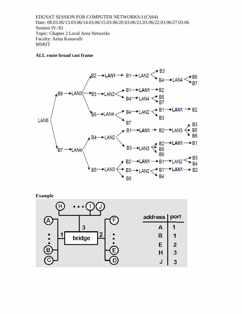
Example
Assume that B1,B3,B4 and B6 are part of spanning tree S1 wants to send a frame to S3 The next slide shows the routes followed by single route broadcast frame and all
routes broadcast framesSingle frame
EDUSAT SESSION FOR COMPUTER NETWORKS-I (CS64)Date: 08.03.06/13.03.06/14.03.06/15.03.06/20.03.06/21.03.06/22.03.06/27.03.06Session IV-XITopic: Chapter 2 Local Area NetworksFaculty: Anita KanavalliMSRIT
ALL route broad cast frame
Example

EDUSAT SESSION FOR COMPUTER NETWORKS-I (CS64)Date: 08.03.06/13.03.06/14.03.06/15.03.06/20.03.06/21.03.06/22.03.06/27.03.06Session IV-XITopic: Chapter 2 Local Area NetworksFaculty: Anita KanavalliMSRIT
• Suppose C sends frame to D and D replies back with frame to C• C sends frame, bridge has no info about D, so floods to both LANs
– bridge notes that C is on port 1– frame ignored on upper LAN– frame received by D– D generates reply to C, sends– bridge sees frame from D– bridge notes that D is on interface 2– bridge knows C on interface 1, so selectively forwards frame out via
interface
Mixed media bridges
Interconnect LANs of different types Example ethernet and token ring These differ in frame format, opeartion and speed and these issues to be taken
care of Since the frame formats are different reformatting is done and new FCS is used.
But adds processing overhead. Since the data rate is different the bridge should have sufficient buffering capacity Two approaches used are : translational bridging
source route transparent bridging
Switch

EDUSAT SESSION FOR COMPUTER NETWORKS-I (CS64)Date: 08.03.06/13.03.06/14.03.06/15.03.06/20.03.06/21.03.06/22.03.06/27.03.06Session IV-XITopic: Chapter 2 Local Area NetworksFaculty: Anita KanavalliMSRIT
• used to concentrate connectivity• combine the connectivity of a hub with the traffic regulation of a bridge• switch frames from incoming ports to outgoing ports providing each port with full
bandwidth• provide separate data paths
switch functions
– Address learning– Forward/filter decision– Loop avoidance
VLANs
• In a typical shared LAN...– Users are grouped physically based on the hub they are plugged into– Routers segment the LAN and provide broadcast firewalls
• In VLANs...– you can group users logically by function, department or application in use– configuration is done through proprietary software– VLANs can logically segment users into different subnets (broadcast
domains)– Broadcast frames are only switched between ports on the switch or
switches with the same VLAN ID.– Users can be logically group via software based on:
• port number• MAC address• protocol being used• application being used

EDUSAT SESSION FOR COMPUTER NETWORKS-I (CS64)Date: 08.03.06/13.03.06/14.03.06/15.03.06/20.03.06/21.03.06/22.03.06/27.03.06Session IV-XITopic: Chapter 2 Local Area NetworksFaculty: Anita KanavalliMSRIT
The above figure shows the difference between a LAN and a VLAN• VLANs...
– work at Layer 2 & 3– control network broadcasts– allow users to be assigned by net admin.– provide tighter network security
The figure shows the formation of a VLAN
• A router provides connection between different VLANs• For example, you have VLAN1 and VLAN2.
– Within the switch, users on separate VLANs cannot talk to each other(benefit of a VLAN!)
– However, users on VLAN1 can email users on VLAN2 but they need arouter to do it.
• Switches make filtering and forwarding decisions based on data in the frame.• There are two techniques used.
– Frame Filtering--examines particular information about each frame (MACaddress or layer 3 protocol type)
– Frame Tagging--places a unique identifier in the header of each frame as itis forwarded throughout the network backbone.

EDUSAT SESSION FOR COMPUTER NETWORKS-I (CS64)Date: 08.03.06/13.03.06/14.03.06/15.03.06/20.03.06/21.03.06/22.03.06/27.03.06Session IV-XITopic: Chapter 2 Local Area NetworksFaculty: Anita KanavalliMSRIT
• Three methods for implementing VLANs– Port-Centric– Static– Dynamic
• Each switched port can be assigned to a VLAN. This...– ensures ports that do not share the same VLAN do not share broadcasts.– ensures ports that do share the same VLAN will share broadcasts.
VLAN benefits
• Traveling Users– 20% to 40% of work force moves every year
• net admin’s biggest headache• largest expense in managing networks. Moves may require...
– recabling– readdressing and reconfiguration
– VLANs provide a way to control these costs. As long as the user stillbelongs to the same VLAN...
• simply configure the new switch port to that VLAN• router configuration remains intact
– Routers provide an effective firewall against broadcasts– Adding VLANs can extend a router’s firewall capabilities to the “switch
fabric”– The smaller the VLAN, the smaller the number of users that are effected
by broadcasts– Shared LANs are easy to penetrate...simply plug into the shared hub.– VLANs increase security by ...
• restricting number of users in a VLAN• preventing user access without authorization• configuring all unused ports to the “Disabled” setting• control access by
– addresses– application types– protocol types
• Hub Replacement & Segmentation– The ports on a non-intelligent hub can only be assigned one VLAN.– Replacing hubs with switches is relatively cheap compared to the benefit
gained.– In the graphic, replacing the core hub in an extended star topology with a
VLAN capable switch effectively microsegments one shared LAN intosix.
________________________________________________________________________