
Edn Best of Design Ideas 2012
25
A SPECIAL SUPPLEMENT TO EDN DESIGN IDEAS the best of OCTOBER 2012
Transcript of Edn Best of Design Ideas 2012

A SPECIAL SUPPLEMENT
TO EDN
DESIGNIDEA
Sthe best of
120828_URL_EDN_Snipe.indd 1 8/27/12 9:16 AM
OCTOBER 2012

the best of
DESIGNIDEA
S
A S P E C I A L S U P P L E M E N T T O E D N
BRAND DIRECTORPatrick Mannion
1-631-543-0445;[email protected]
CHIEF TECHNICAL EDITOR Rich Pell
1-516-474-9568; [email protected]
EXECUTIVE EDITOR
Suzanne Deffree1-631-266-3433;
MANAGING EDITOR, PRINT AND ONLINE
Amy Norcross 1-781-734-8970;
SENIOR TECHNICAL EDITORSteve Taranovich
1-631-413-1834; [email protected]
ASSOCIATE EDITORJessica MacNeil1-212-600-3243;
ASSOCIATE EDITORDiana Scheben
1-631-983-7693; [email protected]
ART DIRECTORGiulia Fini-Gulotta
PRODUCTIONAdeline Cannone
Andrew Barkus
ADVERTISER INDEX
Coilcraft. . . . . . . . . . . . . . . . . . . . .C-4Digi-Key Corp. . . . . . . . . . . . . C-1, C-2Fox Electronics . . . . . . . . . . . . . . . . 9Silicon Labs Inc . . . . . . . . . . . . . . . . 7
For a complete list of editorial contacts,
see http://ubmelectronics.com/editorial-contacts
COVER IMAGE: DANIEL VASCONCELLOS
4 letter from the EDITOR
6 the best of ANALOG❯ How to recover a pulse signal
with a large capacitance load❯ Simple reverse-polarity-
protection circuit has no voltage drop
❯ Obtain a gain of 450 from one vacuum tube
11 the best of COMPONENTS & PACKAGING❯ Build an op amp
with three discrete transistors❯ Automatic night-light feeds
directly from the ac line❯ Use a transistor as a heater
13 the best of LEDs❯ Adjust power-efficient
LED switch to any light intensity
❯ Drive 16 LEDs with one I/O line
❯ Offline supply drives LEDs
16 the best of POWER❯ Convert 1 to 5V signal
to 4- to 20-mA output❯ Inverting level-shift circuit has
negative potential❯ Complementary-pair dc/dc
converter simultaneously doubles, inverts supply voltage
19 the best of SYSTEMS❯ Wireless temperature monitor
has data-logging capabilities❯ Microcontroller drives
piezoelectric buzzer at high voltage through one pin
❯ Logic gates form high-impedance voltmeter
22 the best of TEST & MEASUREMENT❯ Use a photoelectric-FET
optocoupler as a linear voltage-controlled potentiometer
❯ Minimize noise in power-supply measurements
❯ Probing system lets you test digital ICs
26 have your own DESIGN IDEA to share?
OCTOBER 2012 | EDN Best of Design Ideas 3[ www.edn.com ]

4 EDN Best of Design Ideas | OCTOBER 2012 [ www.edn.com ]
THE EDITORTHE EDITORletter from
I recently had the opportunity to see EDN’s print archives. The vault area, housed in our Bedford, MA, office, stores original copies that date back to issue No. 1, published as Electrical Design News on May 8, 1956. I was six years old when EDN debuted.
As I sat down and leafed through the 122-page first edition, the first piece that caught my eye was the editorial by Milton Sol Kiver, the publication’s first editor and the author of Transistors in Radio, Television, and Electronics, published by McGraw-Hill in 1959.
“We are beginning what we believe will be a helpful service to electrical design engineers,” Kiver wrote. “ ‘What,’ we asked, ‘would you desire most to see in an electrical publication?’ The response was as direct as it was unanimous … a magazine of design ideas.”
The editorial continues: “No engineer, we found, can ever get enough good ideas. Ideas represent the most important piece of property in every engineering department, whether it be concerned with the evolution of fantastically complex and intricate computers or merely a simple, two-piece widget that sells for 18 cents. Ideas are what every engineering organization has in common—and will continue to have in common for as long as they remain in business.”
The aim of Electrical Design News, Kiver wrote, was “to provide you with a maximum of ideas which will help you solve present or future problems or perhaps suggest methods of approach that were never even considered.”
How interesting that, 56 years later, engineers still have the same need and hunger for Design Ideas. As the new Design Ideas editor, as well as a longtime EDN reader, I truly value their content. Ever since I graduated from New York University’s School of Engineering in 1972, I have been tearing out Design Ideas and putting them in folders for near- or far-term use as references for my designs.
Design Ideas—community driven, and offering inspired, hands-on, practical, useful circuit-design contributions—have always resonated deeply with EDN’s audience. To highlight those contributions, and the engineers behind them, we collected the most popular Design Ideas published since January 2011 in six categories—Analog, Components and Packaging, LEDs, Power, Systems, and Test and Measurement—and in late August asked our online readers to vote for their favorites. You responded in force. The pages that follow include our Readers’ Choice in each category, as well as a collection of other popular Design Ideas.
As always, you can find many more Design Ideas online at www.edn.com/designideas. You might even want to share a Design Idea of your own with the EDN community. For information on that process, take a look at page 26 of this supplement, or go to www.edn.com/4394666.
Steve Taranovich, Senior Technical Editor, EDN
“IDEAS ARE WHAT EVERY ENGINEERING ORGANIZATION HAS
IN COMMON,” OUR FIRST EDITOR, MILTON SOL KIVER,
WROTE BACK IN 1956. HOW INTERESTING
THAT, 56 YEARS LATER, ENGINEERS STILL HAVE THE SAME
HUNGER FOR DESIGN IDEAS.
the best of
DESIGNIDEA
S

↘ In some applications, it is neces-sary to transmit square waves
across a long cable. Long cables, how-ever, typically have high capacitance, which can significantly affect the sig-nal’s wave shape. As such, the signal’s frequency and duty cycle need to be maintained if the signal is to remain free from distortion. This Design Idea dis-cusses this phenomenon and offers a simple solution.
Figure 1 illustrates a common solution used to reconstruct a square wave at the end of a long cable (47-pF cable capacitance). VIN0 is the signal to be transmitted. The signal at VIN1represents the signal at the end of the cable. You can see that this signal is distorted by the charge and discharge of the parasitic capacitance of the cable. Furthermore, the gate (IC2) sees the ris-ing and falling edges differently, so the reconstructed output signal will not be an accurate representation of the origi-nal digital signal.
The results in Figure 2 show that you cannot recover input pulse with a simple logic gate. You need to find a dif-ferent method to detect the rising and falling edges of the digital circuits. A differentiator can be used to detect the square-wave edges because the output of the RC circuit rises after the rising edge and falls after the falling edge of the square wave. Remember that the differ-entiator output is proportionate to the rate of change of the output signal, so it moves positively for increasing signals and negatively for decreasing signals.
The design in Figure 3 uses a dif-ferentiator. Figure 3 also shows the
simple gate solution (IC2) for compari-son. In this example circuit, you can see how the simple gate solution does not
effectively solve the problem. Note that the signal at VIN1 is from the charging and discharging of C2 times R6. In this
How to recover a pulse signal with a large capacitance loadChenan Tong, Texas Instruments
EDN DI-TONG Fig 1.eps DIANE
+
+
5V
V15
VIN0
VOUT0
VIN1
C247 pF
IC2
R6100
R510k
1 2
SN7407
5V
5
VIN0
VIN1
VOUT0
0
0
0
5
5
0 50μ 100μ 200μ150μ
EDN DI-TONG Fig 2.eps DIANE
Figure 1 Shown is a common pulse-reconstruction solution.
Figure 2 Simulation results for the common pulse reconstruction show that you cannot recover the input pulse with a simple logic gate.
6 EDN Best of Design Ideas | OCTOBER 2012 [ www.edn.com ]
EDN DI-TONG Fig 2.eps DIANE
−
+
−
+
−
+
+
+
+
5V
V15
VIN0
VOUT0
VOUT1
VIN1
C2470 pF
C410 pF
C62.2 pF
dVIN/dT
C54.7 pF
IC2
IC1
R6100
R10330
R78.2k
R820k
R11100
VS22.5
R1310k
R12220
R920k
R510k
1 2
SN7407
SN7407
5V
IC3OPA365IC4
TLV3501
5V
5V
1 2
5V
+
DESIGNIDEAS: ANALOGDESIGNthe best of READERS'C
HO
ICE
Figure 3 By differentiating the RC signal, you can reconstruct a signal that more closely resembles the original square wave.

example, C2 is 470 pF, or 10 times larger than the example in Figure 1. When the input pulse is high (after the rising edge), the capacitor voltage increases. The differentiator output is negative for increasing capacitor voltage. When the input pulse is low (after the falling edge), the capacitor voltage decreases. The differentiator output is positive for increasing capacitor voltage.
Thus, by differentiating the RC sig-
nal you can reconstruct a signal that more closely resembles the original square wave. A comparator follows the differentiator output to create a sharp square-wave output.
Figure 4 shows the simulation results for the circuit in Figure 3. The input signal is a 20-kHz square wave with a duty cycle of 20%. The output of IC2clearly does not reproduce the original signal. In fact, IC2 does not even detect
most of the pulses. The differentiator’s output looks like a smoothed inver-sion of the original digital signal. The comparator converts the differentiator output to a sharp square wave that accu-rately matches the frequency and duty cycle of the original signal. Specifically, the overall error in the duty cycle for this example is approximately 10%.
With this circuit, you can easily implement pulse recognition after a long cable and heavy capacitance load. This method produces pulse transmis-sion with low distortion so that the fre-quency and duty cycle of the original signal are preserved.EDN
ACKNOWLEDGMENTSpecial thanks to Arthur Kay and Matthew Hann of Texas Instruments for contributing their technical expertise in this subject area.
REFERENCES1 “Tutorial 7 of 8: The Op-amp Differentiator Amplifier,” Electronics-Tutorials.ws, http://bit.ly/PT8kLM. 2 OPA365 data sheet, Texas Instruments, http://bit.ly/UNNAWp.
↘ Common methods of reverse-voltage protection employ
diodes to prevent damage to a circuit. In one approach, a series diode allows
current to flow only if the correct polar-ity is applied (Figure 1). You can also use a diode bridge to rectify the input so that your circuit always receives the
correct polarity (Figure 2). The draw-back of these approaches is that they waste power in the voltage drop across the diodes. With an input current of 1A, the circuit in Figure 1 wastes 0.7W, and the circuit in Figure 2wastes 1.4W.
This Design Idea suggests a simple method that has no voltage drop or wasted power (Figure 3).
Simple reverse-polarity-protection circuit has no voltage dropAruna Prabath Rubasinghe, University of Moratuwa, Moratuwa, Sri Lanka
8 EDN Best of Design Ideas | OCTOBER 2012 [ www.edn.com ]
5
0
0
0
4
5
0
0
5
2
VIN0
VOUT0
VOUT1
VIN1
dVIN/dT
0 50μ 100μ 150μ 200μ
EDN DI-TONG Fig 4.eps DIANE
Figure 4 In these simulation results for differentiator-plus-comparator reconstruction, the differentiator output looks like a smoothed inversion of the original digital signal.
EDN 111020DI5173 Fig 1.eps DIANE
VIN
D1
VOUT
EDN 111020DI5173 Fig 2.eps DIANE
VIN VOUTD1BRIDGE
Figure 1 A series diode protects systems from reverse polarity but wastes power in diode losses.
Figure 2 You can use a bridge rectifier so that your system works no matter what the input polarity is. This circuit wastes twice the power, in diode losses, of the circuit in Figure 1.
DESIGNIDEAS: ANALOGDESIGNthe best of

Select a relay to operate with the reverse-polarity voltage. For example, use a 12V relay for a 12V supply sys-tem. When you apply correct polarity
to the circuit, D1 becomes reverse-biased, and the S1 relay remains off. Then connect the input- and output-power lines to the normally connected
pins of the relay, so current flows to the end circuit. Diode D1 blocks power to the relay, and the protection circuit dissipates no power.
• Lower cost than you're paying now (much lower...call for a quote!)
• Faster delivery (samples shipped from Fox the next day; production quantities in days, not weeks!)
• 1 picosecond phase jitter (10X better than programmables!)
• Choice of 2.5 V or 3.3 V supply voltages
• Custom frequencies from 0.75MHz to 1.350GHz (the exact frequency you need, without a premium and without delay)
• 7 x 5 mm, 5 x 3.2 mm and 3.2 x 2.5 mm package sizes
• Choice of XOs and VCXOs
• Internal serial ID with comprehensive traceability
• And a lot more!!!
Like we said...XpressO changes everything. Details await you on our web site! Once again...Fox Rocks!
We’re On Your Frequency.An Integrated Devices Technology, Inc. Company
888-GET-2-FOX (888.438.2369)Outside the US: +1.239.693.0099e-mail: foxonline.com/email.htm
www.foxonline.com
s
EDN 111020DI5173 Fig 4.eps DIANE
D21N5818
B112V
D11N5818
R11k
S112V
VOUT
D3REDLED
NO NC
EDN 111020DI5173 Fig 3.eps DIANE
D21N5818
B112V
D11N5818
R11k
S112V
VOUT
D3REDLED
NO NC
Figure 3 You can wire a relay switch to pass power to your system with no power loss. D2 clamps inductive kicks from the relay coil.
Figure 4 With reversed input voltage, the relay switch engages, interrupting power to the system, and the LED lights.
OctOber 2012 | EDN best of Design Ideas 9[ www.edn.com ]

When you apply incorrect reversed polarity, diode D1 becomes forward-biased, turning on the relay (Figure 4). Turning on the relay cuts the power supply to the end circuit, and red LED
D3 turns on, indicating a reverse volt-age. The circuit consumes power only if reverse polarity is applied. Unlike FETs or semiconductor switches, relay contact switches have low on-resis-
tance, meaning that they cause no voltage drop between the input supply and the circuit requiring protection. Thus, the design is suitable for systems with tight voltage margins.EDN
↘ A direct-conversion radio receiver required an audio gain of 450 from a pentode vacu-
um tube. A pentode has a high transconduc-tance—that is, the ratio of the change in plate current to the change of the control grid voltage that caused it. To get high gain, however, it needs a high load impedance. RF applications with pen-todes often used LC-tuned circuits in their plate loads in which the impedance at resonance and, therefore, the gain is high. It is typically impos-sible to implement a high load impedance using an untuned circuit because of the dc requirements of the tube.
For instance, a 6AU6 pentode vacuum tube needs a quiescent plate current of approximately 5 mA (Figure 1). If the quiescent dc plate volt-age is to be 60V, the load resistance must be no more than 12 kΩ. The 0.5-MΩ plate resistance of the tube and the 1-MΩ load of the next stage are negligible with respect to the 12-kΩ load. With a transconductance of 3900 microsiemens, those requirements demand an audio gain of 45. You can easily achieve this gain with a triode tube.
To get a high load impedance with an untuned plate circuit, you can use a transistor current source for the tube (Figure 2). The transistor has no gain but functions as an active load for the tube and supplies the 5-mA plate current. You adjust the 500Ω potentiometer to obtain 60V dc at the plate. The gain of the circuit is approximately 450. This gain implies a 150-kΩload impedance that the transistor supplies in parallel with the plate resistance and the resis-tance of the next stage. Alternatively, you can use two triode tube circuits in series, each having a gain of 21.EDN
Obtain a gain of 450 from one vacuum tubeLyle Russell Williams, St Charles, MO
10 EDN Best of Design Ideas | OCTOBER 2012 [ www.edn.com ]
EDN120607DI5268 Fig 1.eps DIANE
+
–470 10 µF
0.001 µF
0.01 µF6AU6
120V DC
12k
1M500k
INPUT
OUTPUT
Figure 1 A 6AU6 pentode vacuum tube needs a quiescent plate current of approximately 5 mA.
EDN120607DI5268 Fig 2.eps DIANE
+
–470 10 µF
0.001 µF
0.01 µF6AU6
120V DC
200
1M500k
120k
500
1k
MPSA93
OUTPUT
INPUT
Figure 2 To get a high load impedance with an untuned plate circuit, you can use a transistor current source for the tube.
RF APPLICATIONS WITH PENTODES OFTEN USED LC-TUNED CIRCUITS IN THEIR PLATE LOADS.
DESIGNIDEAS: ANALOGDESIGNthe best of

DESIGNIDEAS: COMPONENTS & PACKAGINGDESIGNthe best of
↘ You can use three discrete transis-tors to build an operational
amplifier with an open-loop gain great-er than 1 million (Figure 1). You bias the output at approximately one-half the supply voltage using the combined voltage drops across zener diode D1, the emitter-base voltage of input transistor Q1, and the 1V drop across 1-MΩ feed-back resistor R2.
Resistor R3 and capacitor C1 form a compensation network that prevents the circuit from oscillating. The values in the figure still provide a good square-wave response. The ratio of R2 to R1determines the inverting gain, which is −10 in this example.
You can configure this op amp as an active filter or as an oscillator. It drives a load of 1 kΩ. The square-wave response is good at 10 kHz, and the output reduc-
es by 3 dB at 50 kHz. Set the 50-Hz low-frequency response with the values of the input and the output capacitors. You
can raise the high-frequency response by using faster transistors and doing careful layout.EDN
Build an op amp with three discrete transistorsLyle Russell Williams, St Charles, MO
EDN111117DI5215 Fig 1.eps DIANE
Q1
2N3904
Q2
Q3
2N3904
2N3906R1
100k
R47.5k
D11N4728A
C15.1 nF
C33.3 μF
R54.7k R3
75kR61k
R21M
C233 nF
9V
Figure 1 This ac-coupled inverting op amp has an open-loop gain of 1 million. R1 and R2 set a closed-loop gain of −10.
OCTOBER 2012 | EDN Best of Design Ideas 11[ www.edn.com ]
↘ There are many approaches to the problem of activating a light when
it becomes dark, and a recent Design Idea covers this topic (Reference 1). Some approaches require a dc power supply and an electromechanical relay, but a better approach involves feeding the device
directly from the ac line, minimizing the number of components (Figure 1).
The heart of the device is a light-sen-sitive cadmium-sulphide resistor, PR, with a resistance of approximately 200 kΩ in the dark, decreasing to a few kilohms in the light. PR and capacitor C1 form an
ac-voltage divider. In daylight, the voltage across PR is too low to generate the required gate-trigger current to turn on bidirection-al ac switch Q1, thus keeping the load—usually a lamp—off. When it becomes dark, PR’s resistance rises, resulting in an increase in the TRIAC’s gate cur-rent that triggers the TRIAC and lights the lamp.
The circuit uses inexpensive, off-the-shelf components, including the VT90N1 photoresistor; a 0.1-μF, 275V capacitor; and an L2004F61 TRIAC with a load current of 4A rms, a peak blocking voltage of 200V, and a gate-trigger current of 5 mA. The exact speci-fications of these components are not critical; you could use others instead.
Editor’s note: Attributes worth men-tioning include the fact that the capacitor introduces a phase shift, which places the peak of the gate voltage close to the zero crossing of the load’s sine wave for opti-mum turn-on timing. Another benefit is thermal hysteresis, which occurs due to the reduction of the required triggering voltage and current as the TRIAC warms up after the initial turn-on.EDN
REFERENCE1 Tran, Chau, “Simple night-light uses a photoresistor to detect dusk,” EDN, Dec 15, 2011, pg 49, http://bit.ly/HPi1GG.
Automatic night-light feeds directly from the ac lineAbel Raynus, Armatron International Inc, Malden, MA
EDN120510DI5277 Fig 1.eps DIANE
PRVT90N1
Q1L2004F61
C10.1 μF275V
R110k¼W
23
1
LOAD
120V AC
NEUTRAL
Figure 1 The photoresistor activates the TRIAC and the load when darkness falls.
READERS'CH
OIC
E

↘ It is common to use transistors for driving resistive heating ele-
ments. However, you can use the heat that a power transistor dissipates to advantage in several situations, elimi-nating the need for a separate heating element because most transistors can safely operate at temperatures as high as 100°C.
A typical example is in a biological laboratory, in which maintaining the temperature of samples in microliter-sized cuvettes is a common requirement. The space/geometry constraint and the <100°C upper-temperature limit are the basic factors of the idea.
You can use an N-channel IRF540 MOSFET to directly heat and control the temperature of a biological sample from ambient to 45°C. Figure 1 shows a simple on/off-type control circuit in which an LM35, IC1, is the tem-perature sensor, whose output a DPM
(digital panel meter) can display. IC2 compares the voltage that VR1 sets with the output of the LM35 to turn on Q2 accordingly, with the positive feedback through R9 providing a small amount of hysteresis. S1 switches the DPM between a set value and the actual temperature readout. You derive the reference voltage from a TL431 shunt regulator (not shown). The LED lights up when Q2 is on.
IC1 and Q2 thermally mount on the metal block that forms the sample holder; use thermal grease on both components for maximum heat transfer. Note that the mounting tab of the TO-220 pack-age electrically connects to the drain, and you may need to insulate it from the cuvette with a thermal pad. Setting bias control VR3 for a Q2 current of 270 mA is sufficient to hold the cuvette at 45°C.
Be sure to set VR3 to minimum power during initial power-up; if you
set it for maximum power, you could apply 24V to Q2’s gate-to-source volt-age, which is rated for a maximum of only 20V. You can extend the temper-ature range by changing the voltage divider comprising R1, R2, and VR1. The design includes a safety cutoff circuit (not shown) in case the temperature gets too high.
Various other options are also pos-sible applications for this circuit. These applications include linear control, pulse-width modulation, and the use of a PID (proportional-integral-deriva-tive) controller, to name a few.EDN
Use a transistor as a heaterREC Johnson, B Lora Narayana, and Devender Sundi,Center for Cellular and Molecular Biology, Hyderabad, India
12 EDN Best of Design Ideas | OCTOBER 2012 [ www.edn.com ]
YOU CAN USE THE HEAT THAT A POWER TRANSISTOR DISSIPATES TO ELIMINATE THE NEED FOR A SEPARATE HEATING ELEMENT.
EDNDI5258 Fig 1.eps DIANE
−
+
IC2TL072
R510k
R410k
R310k
R282
R11k
CWVR1100
CWVR35k
CWVR250k
S1
R91M
R722k
R61k
R82.2k5W
4
–12V
–12V
12V
12V
6
5
8
7
DPMCALIBRATION
SET TEMPERATURE29 TO 65°C
SET TEMPERATURE
CURRENTSET
VREF4.2V
3.6 mA
IC1LM35
0/P=10 mV/C
DPM TEMPERATUREREADOUT1°C=1 mV
D11N4148
D21N4148
Q1
Q2
BC547
LED
12V
12V
BIASSET
IRF540
Figure 1 IC1 senses the temperature of the item that Q2 heats, and the temperature remains at the level that VR1 sets.
DESIGNIDEAS: COMPONENTS & PACKAGINGDESIGNthe best of

↘ You can use an LED as a photo-electric sensor. A previous Design
Idea shows that such a switch is highly power-efficient, consuming almost no power (Reference 1). You cannot, how-ever, adjust that configuration to switch at the desired light intensity. You can adjust the circuit in this Design Idea to any threshold level of light intensity necessary to maintain the on state of the photoelectric switch while retaining almost the same power efficiency of the original circuit (Figure 1).
Illuminating the reverse-biased green LED with ambient light causes the small current that flows through the LED to form the base current of the BC549 NPN transistor, which is amplified and passed on to the base of the BC177 PNP transistor. A magnified version of this current flows through the emitter of the BC177. The voltage drop across the emitter resistor depends on its value and the current flowing through it, which in turn determines the voltage drop across the CE terminals of the BC549.
By adjusting the value of the series emitter resistor, you can set a voltage corresponding to logic zero of a CMOS gate for any desired intensity of light falling on the green LED. This intensity depends heavily on the response of the green LED and the current gains of the two transistors, so you select the resistor value by shorting out combinations of the series string of resistors and use the 10-MΩ potentiometer as a fine adjust-ment. Once you find a suitable value, you can remove the unused resistors from your circuit.
When the ambient-light intensity falls below this level, both the base current of the BC549 and the cur-rent through the emitter series resis-tors decrease. This decrease raises the input voltage at the CD4011 logic gate higher than the CMOS switching threshold. The typical gate sourcing current at a 3V output is approximately 3 to 4 mA per gate; running three gates in parallel delivers approximately 10 mA to the white LED. You can use inverting or noninverting gates for the same result. The circuit still retains its power efficiency because the required
series-resistor values normally exceed 10 MΩ.
You can check a green LED’s suitabil-ity for use as a photodiode by meas uring the voltage drop across the LED with a 200-mV digital multimeter. If the LED is suitable as a photoelectric sensor, you will see a voltage of 0.3 to 1 mV across it, and this voltage changes with the intensity of light falling on the LED.EDN
REFERENCE1 Baddi, Raju R, “Use LEDs as photodiodes,” EDN, Nov 18, 2010, pg 45, http://bit.ly/HaLtFu.
Adjust power-efficient LED switch to any light intensityRaju Baddi, Tata Institute of Fundamental Research, Pune, India
EDN120510DI5261 Fig 1.eps DIANE
WHITELED
GREENLED
CD4011/CD4081/CD4001BC549
BC177
10k
20M
10M
30M 40M
5V
Figure 1 The photocurrent through the green LED amplifies to CMOS-logic levels to turn on the white LED when ambient light falls.
DESIGNIDEAS: LEDsDESIGNthe best of
↘ Over the last few years, several Design Ideas have described how
to use just a few microcontroller I/O pins to drive many LEDs (references 1through 7). The circuit in Figure 1 can
drive 16 LEDs with just one pin and two shift registers. You can use the circuit to drive long-dot-bar or two seven-seg-ment-digit displays. Adding multiplex-ing to the same circuit enables it to
drive eight seven-segment LED digits.The microcontroller drives the shift
registers’ clock inputs. That signal also passes through an RC filter and drives data inputs A and B. A 100-kΩ resis-tor, R, and the A and B input pins’ capacitances form the RC filter (Figure 2), producing time delay of approxi-mately R×C×ln2=100 kΩ×(5 pF+5 pF)×0.7=0.7 μsec.
Drive 16 LEDs with one I/O lineZoran Mijanovic and Nedjeljko Lekic, University of Montenegro, Podgorica, Montenegro
OCTOBER 2012 | EDN Best of Design Ideas 13[ www.edn.com ]
READERS'CH
OIC
E

To write a logic zero to the shift reg-ister, the microcontroller holds a low level for approximately 2 μsec, which is longer than the time delay. It then sets the signal to a logic one, or high, level. To write a logic one, the microcontroller holds the high level for longer than the time delay. The MCU then makes nega-tive pulses of approximately 0.25 μsec, or two CPU cycles, which is shorter than the time delay and which doesn’t change the logic level at the data inputs.
Figure 3 shows the clock signal in Channel 1 (yellow) and the data signal in Channel 2 (blue). The oscilloscope is a Tektronix (www.tektronix.com) DPO4034 with TPP0850 high-voltage
probes. These probes have 40-MΩinput resistance and only 1.5-pF input capacitance, minimizing distortion.
A rising edge on the clock signal clocks the shift registers. This edge corresponds to the data signal’s local minimum. Figure 3 also shows that the minimum data-signal voltages for logic zero and logic one are 1.3 and 3.1V, respectively. The shift register’s logical threshold is 2.5V.
These voltages guarantee sufficient voltage margins. If your design requires higher margins, vary the signal timing and use a higher resistance for R in Figure 1. This circuit stores 16 bits in shift registers in approximately 35 μsec.
You can view a short video of the circuit in operation and download a code listing, in C, at the online ver-sion of this Design Idea at www.edn.com/4368093. The software turns on the LEDs one by one every 500 msec until all LEDs are on. It then turns off all the LEDs and repeats the cycle.EDN
REFERENCES1 Anonymous, “Microcontroller provides low-cost analog-to-digital conversion, drives seven-segment displays,” EDN, May 10, 2007, pg 80, http://bit.ly/hrcp8g.2 Raynus, Abel, “Squeeze extra outputs from a pin-limited microcontroller,” EDN, Aug 4, 2005, pg 96, http://bit.ly/gX723N.
14 EDN Best of Design Ideas | OCTOBER 2012 [ www.edn.com ]
EDN 110609DI5133 Figure 1.eps
PB5
PB3
PB4
GND
VCC
PB2
PB1
PB0
IC1
ATTINY13
1
2
3
4
8
8
9
12
76
5
5V
5V
R100k
R1470
R2470
R3470
R4470
R5470
R6470
R7470
R8470
IC274HC164
CLK
CLR
3456
10111213
8
9
1 AB
AB
2
5V
R9470
R10470
R11470
R12470
R13470
R14470
R15470
R16470
IC374HC164
CLK
CLR
Q0Q1Q2Q3Q4Q5Q6Q7
Q0Q1Q2Q3Q4Q5Q6Q7
3456
10111213
D1
D2
D3
D4
D5
D6
D7
D8
D9
D10
D11
D12
D13
D14
D15
D16
Figure 1 A 16-LED dot-bar/bar-graph display uses two 8-bit serial-input/parallel-output shift registers.
EDN 110609DI5133 Figure 2.eps DIANE
CLOCKR
100k DATA
CA5 pF
CB5 pF
Figure 2 An RC filter provides a 0.7-μsec delay.
DESIGNIDEAS: LEDsDESIGNthe best of
Figure 3 The waveform shows the circuit writing the pattern 1111111111000000 for the display. The upper, yellow trace is the clock signal, and the lower, blue trace is the data signal.

↘ LEDs need power when rectified ac-mains voltage drops during its
cycle. The circuit in Figure 1 lets you use an inductorless, switching, offline power supply as an LED driver for emer-gency-exit signs and neon-light replace-ments. The design uses off-the-shelf components, offers efficient operation without an inductor in the dc side of the circuit, has no high-voltage capacitors,
operates directly from either 120 or 230V ac, has minimal power dissipa-tion, and has adjustable output voltage.
The circuit operates by controlling the conduction angle of MOSFET Q2. When the rectified ac voltage is below the high-voltage threshold, VTH, which D1 sets, the series pass transistor turns on. The series pass transistor turns off when the output storage capacitor, C2,
charges up to the regulation point.The circuit’s output voltage decays
when Q2 is off and when the recti-fied ac is below the output voltage (Figure 2). The load and the value of
C2 determine the amount of decay. The switch con-ducts only when it has low voltages across it, minimizing power dissipa-tion. The output capaci-tor charges on the rising edge of a sine wave, which achieves reasonable effi-ciencies. Fusible resistor R1 provides catastrophic-failure protection and limits input inrush when you first apply ac power. A 15V diode, D2, limits the voltage to the gate of Q2 and limits the voltage across transistor Q1.
The current interrup-tion in the MOSFET causes ringing on the drain-to-source voltage of Q2, creat-ing conducted EMI (electromagnetic interference). The 2.2-mH choke, L1, and capacitor C1 suppress EMI. This design maintains a fairly constant illu-mination over a wide voltage variation in the input. If necessary, you can add a few more such strings to suit your requirements.
Note that this circuit does not pro-vide galvanic isolation. Touching any part of the circuit during operation can give you an electric shock.EDN
Offline supply drives LEDsTA Babu, Chennai, India
SWITCH Q2 ON
VINHIGH
VTH
VREGULATED
VUNREGULATED
Figure 2 Switch Q2 turns on when the rectified ac input voltage drops below a threshold.
L12.2 mH
C1100 nF
R1 10 1W
R239k R4
470k1W
R5100
D139V
C2
220 μF63V
D2
15V
Q1
BC547
Q2IRF830
R310k
LINE
1N40041N4004
1N40041N4004
D31N4004
NEUTRAL
+
I=20 mA
EDN 110407DI5101 DIANE
Figure 1 The transistor and MOSFET provide current to keep the LEDs lit.
3 Jayapal, R, “Microcontroller’s single I/O-port line drives a bar-graph display,” EDN, July 6, 2006, pg 90, http://bit.ly/fjb0MU.4 Lekic, Nedjeljko, and Zoran Mijanovic, “Three microcontroller ports drive 12 LEDs,” EDN,
Dec 15, 2006, pg 67, http:// bit.ly/dRlIBN.5 Gadre, Dhananjay V, and Anurag Chugh, “Microcontroller drives logarithmic/linear dot/bar 20-LED display,” EDN, Jan 18, 2007, pg 83, http://bit.ly/hJCs3j.
6 Benabadji, Noureddine, “PIC microprocessor drives 20-LED dot- or bar-graph display,” EDN, Sept 1, 2006, pg 71, http://bit.ly/kzjQqv.7 Laissoub, Charaf, “Arrange LEDs as seven-segment displays,” EDN, May 26, 2011, pg 55, http://bit.ly/iVGYqH.
The design does noT require an inducTor in The dc side of The circuiT.
OctOber 2012 | EDN best of Design Ideas 15[ www.edn.com ]

↘ Despite the long-predicted demise of the 4- to 20-mA cur-
rent loop, this analog interface is still the most common method of connect-ing current-loop sources to a sensing circuit. This interface requires the con-version of a voltage signal—typically, 1 to 5V—to a 4- to 20-mA output. Stringent accuracy requirements dictate the use of either expensive precision resistors or a trimming potentiometer to calibrate out the initial error of less pre-cise devices to meet the design goals.
Neither technique is optimal in today’s surface-mounted, automatic-test-equipment-driven production environ-ment. It’s difficult to get precise resistors in surface-mount packages, and trimming potentiometers require human intervention, a requirement that is incompatible with production goals.
The Linear Technology LT5400 quad matched resistor network helps to solve these issues in a simple circuit that requires no trim adjustments but achieves a total error of less than 0.2% (Figure 1). The circuit uses two amplifi-er stages to exploit the unique matching characteristics of the LT5400. The first stage applies a 1 to 5V output—typi-
cally, from a DAC—to the noninvert-ing input of op amp IC1A. This voltage sets the current through R1 to exactly VIN/R1 through FET Q2. The same cur-rent is pulled down through R2, so the voltage at the bottom of R2 is the 24V loop supply minus the input voltage.
This portion of the circuit has three main error sources: the matching of R1and R2, IC1A’s offset voltage, and Q2’s leakage. The exact values of R1 and R2are not critical, but they must exactly match each other. The LT5400A grade achieves this goal with ±0.01% error. The LT1490A has <700-μV offset voltage over 0°C to 70°C. This volt-age contributes 0.07% error at an input voltage of 1V. The NDS7002A has a leakage current of 10 nA, although it is usually much less. This leakage current represents an error of 0.001%.
The second stage holds the voltage on R3 equal to the voltage on R2 by pulling current through Q1. Because the voltage across R2 equals the input volt-age, the current through Q1 is exactly the input voltage divided by R3. By using a precision 250Ω current shunt for R3, the current accurately tracks the input voltage.
The error sources for the second stage are R3’s value, IC1B’s offset volt-age, and Q1’s leakage current. Resistor R3 directly sets the output current, so its value is crucial to the precision of the circuit. This circuit takes advantage of the commonly used 250Ω current-loop-completion shunt resistor. The Riedon SF-2 part in the figure has 0.1% initial accuracy and low temperature drift. As in the first stage, offset voltage contrib-utes no more than 0.07% error. Q1 has less than 100-nA leakage, yielding a maximum error of 0.0025%.
Total output error is better than 0.2% without any trimming. Current-sensing resistor R3 is the dominant source of error. If you use a higher-quality device, such as the Vishay PLT series, you can achieve an accuracy of 0.1%. Current-loop outputs are subject to considerable stresses in use. Diodes D1 and D2 from the output to the 24V loop supply and ground help protect Q1; R6 provides some isolation. You can achieve more isolation by increasing the value of R6, with the trade-off of some compliance voltage at the output. If the maximum output-volt-age requirement is less than 10V, you can increase R6’s value to 100Ω, affording
Convert 1 to 5V signal to 4- to 20-mA outputThomas Mosteller, Linear Technology Corp
16 EDN Best of Design Ideas | OCTOBER 2012 [ www.edn.com ]
EDN DI5273 Fig 1.eps DIANE
−
+
Q2
Q1
R5100
R4100
R3250
IC1B½LT1490A
C2220 pF
C1220 pF
D1IN4148
D2IN4148
R622IC1A
½LT1490ANDS7002A
V+
V−
24VLOOP
R110k
¼LT5400
R210k
¼LT5400
1 TO 5VINPUT
−
+
1 μF
24V LOOPSUPPLY
24V LOOPSUPPLY
IRF9Z24S
4- TO 20-mAOUT
Figure 1 Precision matched resistors provide accurate voltage-to-current conversion.
DESIGNIDEAS: POWERDESIGNthe best of READERS'C
HO
ICE
even more isolation from output stress. If your design requires increased protec-tion, you can fit a transient-voltage sup-pressor to the output with some loss of accuracy due to leakage current.
This design uses only two of the four matched resistors in the LT5400 package. You can use the other two for other circuit functions, such as a preci-sion inverter, or another 4- to 20-mA
converter. Alternatively, you can place the other resistors in parallel with R1and R2. This approach lowers the resis-tor’s statistical-error contribution by the square root of two.EDN
EDNDI5260 Fig 1.eps DIANE
Q1
Q2
R33
R43
R12.2k
R53
VOUTPUTCLOCKVINPUTCLOCK
MMBT3640
MMBT2369
C1100 pF100V
C31000 pF
50V
C40.1 μF50V
D1HSMS2805
C2100 pF100V
R22.2k
D2HSMS2805
C51000 pF
50V
C60.1 μF50V
LEVELSHIFTHIGH
LEVELSHIFTLOW
0V
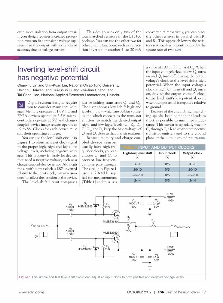
Figure 1 This simple and fast level-shift circuit can adjust an input clock to both positive and negative voltage levels.
↘ Digital-system designs require you to consider many core volt-
ages. Memory operates at 1.8V, I2C and FPGA devices operate at 3.3V, micro-controllers operate at 5V, and charge-coupled-device image sensors operate at −9 to 8V. Clocks for each device must suit their operating voltages.
You can use the level-shift circuit in Figure 1 to adjust an input clock signal to the proper logic-high and logic-low voltage levels, including negative volt-ages. This property is handy for devices that need a negative voltage, such as a charge-coupled-device sensor. Although the circuit’s output clock is 180°-inverted relative to the input clock, that inversion does not affect the function of the device.
The level-shift circuit comprises
fast-switching transistors Q1 and Q2. The user chooses level-shift high and level-shift low, which are dc-bias voltag-es and which connect to the transistor emitters, to match the desired output high- and low-logic levels. C1, R1, D1, C2, R2, and D2 keep the base voltages of Q1 and Q2 close to that of their emitters.
Because memory and charge-cou-pled-device sensors usually have high-fre-quency clocks, you can choose C1 and C2 to prevent low-frequen-cy-noise pass-through. The circuit in Figure 1 uses a 20-MHz sig-nal for measurements (Table 1) and thus uses
a value of 100 pF for C1 and C2. When the input voltage’s clock is low, Q1 turns on and Q2 turns off, driving the output voltage’s clock to the level shift’s high potential. When the input voltage’s clock is high, Q1 turns off and Q2 turns on, driving the output voltage’s clock to the level shift’s low potential, even when that potential is negative relative to ground.
Because of the circuit’s high switch-ing speeds, keep component leads as short as possible to minimize induc-tance. This caveat is especially true for C3 through C6’s leads to their respective transistor emitters and to the ground plane or the output ground return.EDN
Inverting level-shift circuit has negative potential Chun-Fu Lin and Shir-Kuan Lin, National Chiao Tung University,Hsinchu, Taiwan; and Hui-Shun Huang, Jyi-Jinn Chang, and Tai-Shan Liao, National Applied Research Laboratories, Hsinchu
OctOber 2012 | EDN best of Design Ideas 17[ www.edn.com ]
TAbLe 1 Input and output clocksHigh/low level shift
(V)Input clock
(V)Output clock
(V)
3.3/0 0/5 3.3/0
20/10 0/5 20/10
−5/−10 0/5 −5/−10
2/−4 0/5 2/−4

↘ The circuit in this Design Idea uses an intrinsic property of collector
voltages in one-transformer push-pull dc/dc converters: They have a swing of twice the supply voltage. When you implement these circuits with an NPN device, the collector swings from 0V to twice the supply-rail voltage. When you use PNP devices, the collector voltage swings from VCC to an equal amplitude but negative VCC (Reference 1). In this circuit, a complementary pair of transistors, simul-taneously implementing a voltage dou-
bler and a negative-voltage source, drives the two windings of the transformer.
One of the windings of transformer T1 connects to ground, driven by PNP transistor Q1 from VCC (Figure 1). The other winding of T1 connects to VCC, and NPN transistor Q3 drives the lower end to ground. Q2 and Q4 drive Q1 and Q3, respectively. The collectors of Q3 and Q1through resistors R4 and R3 provide cross-coupled drives to Q2 and Q4. R1 and R2form the collector loads for Q2 and Q4. D1and D4 prevent the reverse breakdown of
Q1 and Q3. The drive configuration and the transformer’s winding polarity pro-vide regenerative feedback and self-oscil-lation so that the transformer alternates between positive and negative saturation, inducing voltages to drive transistors Q1and Q3 alternately on and off.
A square wave with an amplitude twice VCC is generated at the collector of Q1, which swings nominally from VCCto the equal but negative output voltage. Simultaneously, a square wave with an amplitude twice the supply-rail voltage is generated at the collector of Q3, which swings nominally from 0V to twice the supply-rail voltage.
D2 and C2 provide half-wave recti-fication and filtering of the Q1 collec-tor waveform generating the negative voltage output. Half-wave rectifica-tion and filtering of the Q3 collector waveform using D3 and C3 generate the doubler’s output.
T1 is 200 turns of bifilar AWG 37 enameled wire wound 1-to-1 on a ferrite toroid core (references 2 and 3). Table 1shows the experimental results with the voltage doubler and negative-voltage-generation circuit operating over an input voltage of 5 to 30V, demonstrating oper-ation over a wide input voltage range and providing power at both outputs simulta-neously at moderate efficiency.EDN
REFERENCES1 Raman, Ajoy, “Voltage doubler uses inherent features of push-pull dc/dc converter,” EDN, Aug 16, 2007, pg 72, http://bit.ly/GTlveF.2 “T503125,” Ceramic Magnetics Inc, http://bit.ly/L3FzeW.3 MN60 manganese-zinc material specs, Ceramic Magnetics Inc, http://bit.ly/KoyO4Y.
Complementary-pair dc/dc converter simultaneously doubles, inverts supply voltageAjoy Raman, Bangalore, India
18 EDN Best of Design Ideas | OCTOBER 2012 [ www.edn.com ]
EDN120419DI5257 Fig 1.eps DIANE
T1
R22.7k
R310k
R12.7k
R410k
D41N4148
D2MBRS1100
D3MBRS1100
C322 μF100V
C222 μF100V
C122 μF100V
D11N4148
VCC
–VOUT
Q3
Q2
Q1
Q4
BCP56
2N23692N2369
BCP53
+
+
OUTPUT-VOLTAGEDOUBLER
–
Figure 1 Cross-coupled regeneration drives switching transistors Q1 and Q3 and the windings of the transformer. The resulting voltage swings at their collectors are rectified to twice the positive and the negative power-supply rails.
DESIGNIDEAS: POWERDESIGNthe best of
TABLE 1 EXPERIMENTAL RESULTSInput
voltage (V)
Input current
(mA)Frequency
(kHz)
Voltage doubler
(V)
Current doubler
(mA)
Negative voltage
(V)
Negative current
(mA)
Input power
(W)
Output power
(W)Effi ciency
(%)
5 253 2.1 7.68 81.7 −3.41 −72.5 1.27 0.87 69
9.97 360 4.05 17.33 115.5 −8.65 −86.5 3.59 2.75 76.6
15 420 6.02 27.2 136 −13.58 −90.5 6.3 4.93 78.2
19.4 400 7.37 34.9 145.4 −18.33 −61.1 7.76 6.19 79.8
25 340 10.47 48.5 97 −23.8 −79.3 8.5 6.59 77.5
30 410 12.07 56.5 113 −27.6 −92 12.3 8.92 72.5

↘ You can use a local temperature sensor and an ASK (amplitude-
shift-keying) transmitter/receiver pair to design a simple wireless temperature-monitoring system with data-logging capabilities. A microcontroller process-
es and displays the temperature reading to the user. The microcontroller’s onboard UART (universal asynchro-nous receiver/transmitter) also allows for data-logging applications.
Local-temperature sensor IC1 detects
the ambient temperature at the device (Figure 1). The output of IC1 is a square wave with a frequency proportional to temperature in kelvins. ASK trans-mitter IC2 modulates the signal onto the carrier frequency of 315 MHz. You
meas ure the output signal’s frequency with a frequency counter. The config-ured scalar multiplier is 1K/Hz when the TS1 pin connects to ground and the TS0 pin connects to VDD. This scalar multiplier is configurable with pins TS1 and TS0. ASK receiver IC3demodulates the sig-nal at the correspond-ing carrier frequency (Figure 2).
Comparator IC4connects to IC3’s RSSI
Wireless temperature monitor has data-logging capabilitiesTom Au-Yeung and Wilson Tang, Maxim Integrated Products, Sunnyvale, CA
EDNDI5230 Fig 1.eps DIANE
IC1MAX6577
IC2MAX1472X1
9.84375 MHz
VDD
VDD
TS0
TS1
OUT3V
0.1 μF
0.47 μF 0.01 μFDATA
12 pF
15 pF
680 pF 220 pF
220 pF
12 pF
X1
X2
PAOUT
GND/PAGND22 pF 15 pF
ENABLE
5k
27 nH
22 nH
5.1
3V
Figure 1 The MAX6577 temperature sensor and 315-MHz MAX1472 ASK transmitter form a wireless temperature-monitoring system.
EDNDI5230 Fig 2.eps DIANE
LNAIN100 pF
100 pF
220 pF
15 pF
470 pF
15 pF
100 pF4.7 pF
120 nH
15 nH
VDD3V
0.01 μF
0.1 μF
0.1 μF
0.1 μF
0.1 μF
0.47 μF
PWRDN
DATAOUTLNASRC
LNAOUT
MIXIN1
MIXIN2
27 nF3V
X1
X2
X14.75687 MHz
GND
5k
DSP DSN DF
−
+IC4
MAX9075
IC5MAXQ2000
IC3MAX1470
3V
1M1M
1.1M
10k
PD
10.7-MHzFILTER
MIXOUT
IFIN1
IFIN2
OPP 1500 pF
10 pF 10 pF
220 pF
COUNTER
TIMER
UART0
LCD DRIVER
T1
P6.0
VCC
1.8VVDDI0 VLCD
3V
32KIN
32KOUT
X332.768 kHz
X216 MHz
TXD0 UARTTX
LCDSEG0-SEG35
VI-502-DP4½-DIGIT
DIGIT DISPLAYHFIN HFOUT GND
Figure 2 An ASK receiver with a microcontroller processes and displays temperature data.
DESIGNIDEAS: SYSTEMSDESIGNthe best of
OCTOBER 2012 | EDN Best of Design Ideas 19[ www.edn.com ]
READERS'CH
OIC
E

(received-signal-strength indicator) with an internal peak detector. The exter-nal RC follows the peak power of the received signal and compares it with a predetermined, resistor-voltage-divider-generated voltage level. Lab experiments show that a threshold of approximately 1.57V generates a valid output on the data-out pin without receiving false read-ings. Adjust this threshold to the proper level for optimal performance. The com-parator’s output is low when the received signal is weak or invalid and high when the received signal is adequate.
Microcontroller IC5 then measures and displays the value of the signal frequency using its integrated timer/counters and LCD-driver peripherals. A counter tracks the number of rising-edge transitions on the input tem-
perature signal, and a timer tracks the elapsed time. After the timer’s 1-sec period elapses, an interrupt occurs. At that moment, the circuit reads the counter value, converts it to Celsius, and displays it on the LCD. The counter then resets to zero to restart the process. The timer automatically reloads once the timer interrupt occurs. UART0 also outputs the resulting temperature. A handheld frequency counter verifies the temperature reading.
The microcontroller monitors the signal power through P6.0, a general-purpose input pin. When the input is logic low, the LCD and UART out-put “no RF” to alert users of possible transmitter issues when the transmitter and receiver are too far apart from each other. The LCD connection follows
the design in the IC’s evaluation kit. Using a look-up table in the data seg-ment of the assembly code enables you to preserve the internal mapping of the display’s A through G segments. This preservation ensures that the display enables the correct segments. Using an RS-232 level converter, the UART out-put sends data to a data-logging device, such as a computer.
Use the MAX-IDE assembler soft-ware to program the device during assembly. The MAXQJTAG board operates with the MAX-IDE to load the code onto the device. You can download the project files at www.edn.com/4368878. This design provides for a 1-sec temperature-refresh rate in 1°C increments, which is within the accu-racy of IC1.EDN
20 EDN Best of Design Ideas | OCTOBER 2012 [ www.edn.com ]
DESIGNIDEAS: SYSTEMSDESIGNthe best of
↘ A previous Design Idea demon-strates how you can use a micro-
controller to drive a piezoelectric buzzer at a high alternating voltage through a four-MOSFET circuit that interfaces to
two of its I/O pins (Reference 1). This expanded Design Idea provides a modi-fication of the previous circuit to save one of the I/O pins of the microcon-troller. Q4’s gate connects to Q2’s drain
rather than a second I/O pin (Figure 1). The microcontroller turns on Q2 by applying a high logic level to the I/O pin, pulling Node A down to a low logic level. This action turns on Q3 and turns off Q4. The voltage on Node B becomes 15V, and Q1turns off. The voltage across the piezoelectric element is now 15V.
The microcontroller then toggles the I/O pin low, turning off Q2. Q1 is also off, so Node A slowly rises to a high logic level through pullup resis-tor R1. When the volt-age on Node A reaches
the switching threshold of the inverter comprising the Q3 and Q4 pair, Q3quickly turns off and Q4 quickly turns on. The consequently low logic level on Node B turns on Q1 and speeds the increase of Node A’s voltage. The 15V across the piezoelectric buzzer is now of the opposite polarity.
R2 weakens the coupling between the output and the input of Q4 due to the presence of the piezoelectric ele-ment. A value of 330Ω for R2 is usually sufficient to suppress high-frequency oscillations that the feedback causes. The drained power from the supply increases if you use low values for R1. Using excessively large values for R1also increases power dissipation by pro-longing the switching of the transistors and associated shoot-through currents. The optimum value for R1 is approxi-mately 1 kΩ.
Saving an I/O pin with this design involves the trade-off of increased power consumption. The circuit’s power consumption is thus one order of magni-tude greater than the circuit described in the previous Design Idea.EDN
REFERENCE1 Ozbek, Mehmet Efe, “Microcontroller drives piezoelectric buzzer at high voltage,” EDN, March 1, 2012, pg 44, http://bit.ly/JyzLpz.
Microcontroller drives piezoelectric buzzer at high voltage through one pinMehmet Efe Ozbek, PhD, Atilim University, Ankara, Turkey
EDN120621DI5297 Fig 1.eps DIANE
Q1R1
Q2 R2 Q4
Q3
15V15V 15V
A B
I/O PIN
Figure 1 One microprocessor I/O pin drives this circuit to generate an alternating voltage across the piezoelectric buzzer.

↘ You can use the circuit described in this Design Idea to estimate
voltages across 10- to 100-MΩ resis-tances. It also works for reverse-biased diodes.
The common CMOS gates in Figure 1 have an input threshold volt-age in which the output swings from logic zero to logic one, and vice versa. The threshold voltage depends on the supply voltage (Figure 2). Because of each CMOS gate’s high input imped-ance, input currents are approximately 0.01 nA. If you apply 5V to 100 MΩ, you get 50 nA. Thus, you can connect the gate input at a point at which it draws a negligible amount of current.
You can vary the CMOS gate’s supply voltage to attain the desired
threshold voltage for the gate input. If you apply the unknown voltage to one of the gate’s inputs and then connect
the other input to the positive-voltage supply, you can vary the supply volt-age, VS, until you reach a point at which the threshold voltage at the input becomes equal to the unknown voltage.
At this point, the output of the sense gate, IC1A, changes from logic zero to logic one. When this event happens, the threshold of the gate passes the unknown voltage. You can estimate the unknown voltage using a graph of threshold voltage versus sup-ply voltage, such as the one in Figure 2. By fitting a parabola or a polyno-mial to the experimentally obtained points—say, some 20 points lying in the supply-voltage range of 2 to 15V—you can estimate the threshold voltage, VT, for any supply voltage.
This circuit has been built and tested. The online version of this Design Idea includes Octave/Matlab code that you can view at www.edn.com/4368072.EDN
Logic gates form high-impedance voltmeterRaju Baddi, Tata Institute of Fundamental Research, Pune, India
−
+
IC1A
R1
R2
IC1B
220
10k
CD4011
MOVINGCOIL
METEROR
LED
+_
DVM
1 TO 15VVARIABLESUPPLY
EDN 110512DI5141 FIGURE 1 DIANE
NOTE: R1 AND R2 ARE IN TENS OR HUNDREDS OF MEGOHMS.
Figure 1 Use CMOS gates and a variable power supply to find an unknown voltage.
EDN 110512DI5141 FIGURE 2 DIANE
7
6
5
4
3
2
1
02 4 6 8 10 12 14 16
SUPPLY VOLTAGE (V)
THRESHOLDVOLTAGE
(V)
*
*
**
*
**
*
**
*
*EXPERIMENTALFIT
Figure 2 The gate’s threshold voltage is nearly linear respective to the power-supply voltage. Download this plot from the online Design Idea at www.edn.com/4368072.
EstimatE thE unknown voltagE using a graph of thrEshold vErsus supply voltagE.
OctOber 2012 | EDN best of Design Ideas 21[ www.edn.com ]
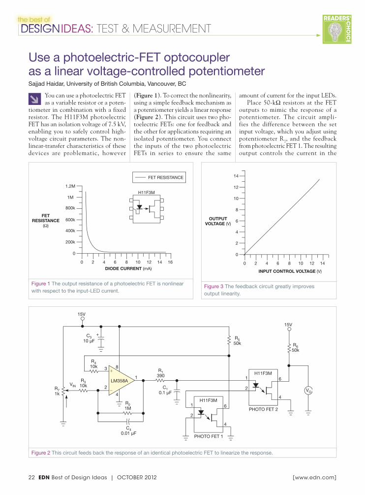
↘ You can use a photoelectric FET as a variable resistor or a poten-
tiometer in combination with a fixed resistor. The H11F3M photoelectric FET has an isolation voltage of 7.5 kV, enabling you to safely control high-voltage circuit parameters. The non-linear-transfer characteristics of these devices are problematic, however
(Figure 1). To correct the nonlinearity, using a simple feedback mechanism as a potentiometer yields a linear response (Figure 2). This circuit uses two pho-toelectric FETs: one for feedback and the other for applications requiring an isolated potentiometer. You connect the inputs of the two photoelectric FETs in series to ensure the same
amount of current for the input LEDs.Place 50-kΩ resistors at the FET
outputs to mimic the response of a potentiometer. The circuit ampli-fies the difference between the set input voltage, which you adjust using potentiometer R7, and the feedback from photoelectric FET 1. The resulting output controls the current in the
Use a photoelectric-FET optocoupleras a linear voltage-controlled potentiometerSajjad Haidar, University of British Columbia, Vancouver, BC
22 EDN Best of Design Ideas | OCTOBER 2012 [ www.edn.com ]
EDNDI5236 Fig 2.eps DIANE
H11F3M6
4
1
2
PHOTO FET 1
H11F3M6
4
1
2
PHOTO FET 2
VO
R650k
R550k
15V
C10.1 μF
C40.01 μF
C310 μF
R1390
R21M
R410k
R310k
R71k
−
+3
2
1LM358A
4
8
+
15V
VIN
Figure 2 This circuit feeds back the response of an identical photoelectric FET to linearize the response.
EDNDI5236 Fig 1.eps DIANE
200k
400k
600k
800k
1M
1.2M
0
0 2 4 6 8 10 12 14 16
DIODE CURRENT (mA)
FETRESISTANCE
(Ω)
FET RESISTANCE
H11F3M
Figure 1 The output resistance of a photoelectric FET is nonlinear with respect to the input-LED current.
DESIGNIDEAS: TEST & MEASUREMENTDESIGNthe best of
EDNDI5236 Fig 3.eps DIANE
14
12
10
8
6
4
2
0
0 2 4 6 8 10 12 14
INPUT CONTROL VOLTAGE (V)
OUTPUTVOLTAGE (V)
Figure 3 The feedback circuit greatly improves output linearity.
READERS'CH
OIC
E

↘ You must minimize noise when measuring ripple in power rails
because the ripple’s amplitude can be low. Oscilloscope probes are essential measurement tools, but they can intro-duce noise and errors. Ground leads, such as those that attach to standard oscilloscope probes, can add noise that’s not present in your circuit to an oscil-loscope’s trace. The wire loop acts as an antenna that picks up stray magnetic fields. The larger the loop area, the more noise it picks up.
To prove this theory, connect the oscilloscope ground lead to the probe tip and move it around. The oscillo-scope will show the noise increasing and decreasing with the ground-lead move-ment. You can use an oscilloscope probe with its ground lead and sockets to build a simple interconnect board (Figure 1).
Start by removing the probe’s cover, which reveals the probe tip. There is a short distance between the tip and the ground ring. You need one of two sockets: a right-angle, or horizontal,
socket or a vertical socket, similar to those in Figure 1.
Solder the center leg of the socket to the output of the power supply, and solder the other leg to the power-supply return. Connect a 0.1-μF surface-mount, stacked ceramic capacitor between the two sockets. This step limits the probe bandwidth to approximately 5 MHz, which further reduces high-frequen-cy noise and lets the lower-frequency ripple pass through. Figure 2 shows the completed interconnect board; Figure 3 shows a schematic of the board.
Insert the probe tip into the socket to measure ripple. You will get a ripple meas-urement without spikes or other noise.
You should use a multilayer stacked ceramic capacitor because it’s better at decoupling high-frequency noise. Electrolytic, paper, and plastic-film capacitors comprise two sheets of metal foil with a sheet of dielectric separating the metal sheets, and these three com-ponents form a roll. Such a structure has self-inductance; thus, the capacitor acts more like an inductor than a capacitor at frequencies higher than a few megahertz.
Figure 4 shows the impedance to the power supply for various stacked-ceramic-capacitor values.EDN
photoelectric-FET LEDs until the feed-back voltage equals the input voltage. The output voltage follows linearly
with the input voltage (Figure 3). You might think that photoelectric FETs bearing the same part number are iden-
tical, but small manufacturing discrep-ancies can be present. Five H11F3M parts have offsets within 3%.EDN
Figure 1 A standard oscilloscope probe has a ground lead that can pick up noise.
Figure 2 Solder wires from the power supply under test to an interconnect board reduce ground-lead length.
EDN 110623DI5114 Figure 3 DIANE
J2C1
0.1 μF
1000 pF100 pF
2.2 μF0.1 μF
0.01 μF
0.001 0.01 0.1 1 10 100 1k 10k
0.001
0.01
0.1
1
10
100
1k
10k
100k
1M
IMPEDANCE (Ω)
FREQUENCY (MHz)
Figure 4 Probe impedance varies with capacitor value.
Figure 3 A ceramic capacitor further reduces high-frequency noise.
Minimize noise in power-supply measurementsJohn Lo Giudice, STMicroelectronics, Schaumburg, IL
OctOber 2012 | EDN best of Design Ideas 23[ www.edn.com ]

24 EDN Best of Design Ideas | OCTOBER 2012 [ www.edn.com ]
↘ This Design Idea describes a sim-ple yet powerful handheld probe
that you can use as both a logic probe and a pulse generator either individually or simultaneously. This feature makes the probe useful for testing DIP digital ICs, such as gates, flip-flops, and counters, using a socketed fixture with three-post jumpers to connect each pin to logic high or logic low or to 5V or ground.
Three pushbutton switches, two dual-color LEDs, and two probe tips are built
into a plastic cylinder, such as an empty, 20g or larger glue-stick tube. The genera-tor’s probe tip hooks to fit onto the test fixture’s jumper pins and mounts onto a spring —such as those in retractable ball-point pens—for flexibility, and it allows the logic-probe tip to move to the output under test. Two of the pushbutton switches set the generator’s quiescent state for a high or low output. The third switch briefly single-pulses the output to the opposite state. If the switch is pressed
for longer than 2 seconds, the output produces a pulse train.
IC1A, an NE556, is a 2-sec mono-stable circuit, which triggers a 1-msec-pulse generator circuit employing gate G1, resistor R1, and capacitor C1(Figure 1a). G4 buffers the circuit. The output of the monostable circuit also passes through G2 and G3 to mask the output of the astable component, IC1B, an NE556 that provides the pulse train. To prevent any spurious pulse from reaching output Probe A when switch S1 is not depressed, keep IC1B deactivated by applying a low voltage to its reset pin 4 through transistor Q1, whose biasing is further guarded by a 0.68-μF capacitor.
When you press switch S1 for a short
Probing system lets you test digital ICsRaju Baddi, Tata Institute of Fundamental Research, Pune, India
EDN DI5286 Fig 1.eps DIANE
IC1ANE556
IC1BNE556
C10.1 μF
8
0.1 μF
0.1 μF
0.47 μF
0.68 μF
10k
10k
10k 10k 10k3.3M
12, 13
S1
S2
S3
14 14
100k100k
7
Q1
9
+
+
G1
G4
G5
G2
G7
G6
G8
G11
G12
G3
G9
G10
R110k
41
2, 6
5100k
100k
PROBE A
PROBE B
470
LM358
2
3
LM358
6
5
1
7
470
470
8
4
LOGICPROBE
10k
10k
10k 2.2k
220k
220k
(a)
(b)
−
+
−
+
7
9
Figure 1 This circuit combines analog and digital functions. Probe A is the pulse-generator probe, and Probe B is the logic probe (a). Although not shown, a 100-μF capacitor should be connected between the supply and ground. Red LEDs indicate logic zero, and green LEDs display logic one (b).
DESIGNIDEAS: TEST & MEASUREMENTDESIGNthe best of

time, IC1A fires and produces a high out-put for approximately 2 sec. The 1-msec pulse from G1, R1, C1, and G4 reaches the pulse Probe A through the XOR function comprising G5 through G8, and
the output of the astable IC1B is masked at G3 from reaching the XOR. If you depress switch S1 for longer than 2 sec, the monostable IC1A times out. This action unmasks G3 and allows the 70-Hz
oscillation from IC1B to reach the XOR.G9 and G10 form a bistable circuit,
which “remembers” the most recently pressed S2 or S3 switch and controls the inverting and noninverting operation of the XOR function. G11 and G12 together drive the dual-color LED to indicate the pulse generator’s polarity. Red indicates that Probe A’s output is mainly logic zero, with the single 1-msec pulse a logic high. Green indicates the opposite.
The LM358 acts as a window-detec-tor logic probe (Figure 1b). With the values in the figure, the red LED lights at Probe B voltages of less than 35% of the supply voltage, and the green LED lights at voltages greater than 65% of the supply voltage. Neither LED lights between these voltages. You may wish to adjust the resistor network to reduce the lower threshold to include the transis-tor-transistor-logic zero of less than 0.8V.
If you use CD4011 quad NAND gates, you can externally power the probe at 4.5 to 15V. Using a CD4093 Schmitt-trigger quad NAND for G1through G4 ensures no spurious oscilla-tions as a result of the slow voltage rise at timing capacitor C1. If your design requires a higher-current generator drive, you can add a pair of NPN and PNP boost transistors to the output.
Figure 2 shows a jig for testing the digital ICs. Configure the 16-pin DIP socket for the device under test with an array of triple-post headers and push-on jumpers. You can connect any pin directly or through a resistor to power or ground to configure power or logic levels. The resistors can be any suitable value; approximately 2 kΩ is appropriate.
To set a TTL low, the pin must con-nect directly to ground. To inject a sig-nal, hook the flexible spring-mounted generator, Probe A (Figure 3), onto the appropriate input post and move logic Probe B to the corresponding output post or pin. See a suggested perf-board layout at www.edn.com/4374947.EDN
RefeRences1 Baddi, Raju, “Logic probe uses six transistors,” EDN, Dec 15, 2010, pg 46, http://bit.ly/n24oau. 2 Rentyuk, Vladimir, “Logic probe uses two comparators,” EDN, Aug 25, 2011, pg 54, http://bit.ly/wtuKgi.
EDN DI5286 Fig 2.eps DIANE
DIGITAL ICUNDER TEST
5V
SIGNAL SIGNALPOWER POWER
PULSE GENERATOR
GEL-PEN REFILL TIPS
GLUE-STICK CAP
LOGIC PROBE DUAL-COLOR LED
PULSE DUAL-COLOR LED
PCB
SCREWS
20g GLUE-STICK TUBE
CONNECTING WIRE
LOGIC PROBE
GEL-PENREFILL PIPE
SPRING (ALSO ACTSAS CONNECTING WIRE)
Figure 3 To inject a signal, hook the flexible spring-mounted generator, Probe A, onto the appropriate input post and then move logic Probe B to the corresponding output post or pin.
Figure 2 Program this test jig with header posts and jumpers for the IC under test.
OctOber 2012 | EDN best of Design Ideas 25[ www.edn.com ]

26 EDN Best of Design Ideas | OCTOBER 2012 [ www.edn.com ]
DESIGN IDEADESIGN IDEAhow to submit a
Have your own Design Idea to share?
O ne of the really cool things about EDN is the Design Ideas section, where readers can post their idea for a new circuit or system, and others can comment on it, suggesting improvements or pointing out flaws. It is common for EDN editors to hear from new EEs how much they appreciate the experienced engineers with whom they
get to work. In some small companies or specialized areas, however, EEs may not have that opportunity. That’s where EDN’s Design Ideas come into play. Readers can post their ideas, and others can chime in on what works—and what doesn’t.
Have an idea for which you’re seeking input or looking to score bragging rights? All you need to do is send your Design Idea to [email protected].
If you want to know more, this list of Design Ideas FAQs might be of assistance:
WHAT ARE DESIGN IDEAS?Design Ideas are short, compact articles (about three to six paragraphs on aver-age) that help you solve problems or show you innovative ways to accom-plish design tasks. The topic is up to you. We review articles that fall into virtually any technology area: analog or digital circuits, programmable logic, hardware-design languages, systems, programming tips, useful utilities, test techniques, and so on. The idea should be useful or innovative or tricky. A Design Idea is not necessarily a complete engineer-ing package. You don’t have to submit a design for your complete system—just the idea that is the heart of your system. To learn what makes a good Design Idea, please spend some time browsing our archive of Design Ideas at www.edn.com/designideas.
HOW DO I SUBMIT A DESIGN IDEA?E-mail a version of your idea, as well as graphics in .tif, .gif, or jpeg format, to [email protected]. Design Ideas must be your original work, and you must not have published them elsewhere.
CAN I SEND IN HAND-DRAWN SCHEMATICS?Sure. Our art department will often redraw the Design Ideas schematics anyway to conform to our selected style. Just make sure the drawing is legible and complete. Include pin numbers of the ICs for the convenience of readers who build the circuit. Label components’ designations (e.g., R2, C3, IC1) if they are mentioned in the text of the article.
Make sure you include component val-ues, ratings, and tolerances, and if you have an unusual component in your design, tell us the manufacturer, source, materials, etc. For instance, if your design involves a homemade inductor, we’ll need to know the core material, wire gauge, and number of turns. For program listings, e-mail a file.
CAN I PUT HYPERLINKS TO RELATED CONTENT IN MY DESIGN IDEA?Absolutely! Links to software down-loads, related articles, additional tech-nical information, white papers, and any related topic are strongly encour-aged. Readers find them very helpful.
HOW LONG DOES IT TAKE TO FIND OUT IF MY DESIGN IDEA IS ACCEPTED?We want to give each Design Idea a fair shake, so we have established internal and external panels of experts in all technical fields to evaluate the articles. The evaluation process can be as short as three weeks to as long as seven. In some cases, it has taken longer to pro-vide feedback to an author. We try not to make a habit of this type of delay, but the large number of Design Ideas submitted sometimes creates a backlog.
DO I GET PAID FOR A DESIGN IDEA?You bet. You won’t get rich, but your idea will be read by hundreds of thousands of your colleagues around the world. If we accept your Design Idea, we pay $150 (American Express Gift Cheque).
CAN I SEND MY DESIGN IDEA TO MORE THAN ONE MAGAZINE AT A TIME?Don’t do it. Most professional pub-lications will reject an article outright if it has been sent to multiple maga-zines. Send your article to only one magazine at a time. If Magazine #1 declines to publish your article, then you’re free to try Magazine #2. Don’t give up; if you have a neat idea, it will get noticed.
WHAT ABOUT TESTING THE DESIGNS? DO YOU DO IT?We cannot emphasize testing enough, but we don’t have the time or facili-ties to do it. Therefore, it’s imperative that you wring out and test your design yourself! If your design is a power sup-ply, for example, make sure it can with-stand temperature extremes, input over-voltages, and output short circuits. Include some measured performance data in the text or table. Make sure there won’t be a problem if any critical component fails. Test, test, test!
TIPS AND REQUIREMENTS:❯ The design entered must be
submitted exclusively to EDN. The design must be original to the author(s), must not have been previously patented or published, and must have been constructed and tested.
❯ Fully annotate all circuit diagrams with the components’ part numbers and electrical values.
❯ Keep it short.
❯ E-mail your idea and graphics and supporting materials in one e-mail, such as with a ZIP file.
❯ Don’t worry about style or grammar, but make sure we can figure out why your Design Idea is clever, how it works, and which applications it suits.
❯ Send questions and completed Design Ideas to [email protected].

cracking the code to systems developmentChips to software, embedded is your playground.
Live at embedded.com.Coming alive at ESC.

WWW.COILCRAFT.COM
®
Superconductors pass current with virtually no resistance.
Our new XAL/XFL inductors do much the same. Their DCR is incredibly low: often half that of similar size parts.
And their current handling is equally impressive. Coilcraft’s proprietary core material has a soft saturation characteristic that
prevents drastic inductance drops during current spikes.
Unlike competitive parts, these inductors don’t suffer from thermal aging. And we give you far more footprint options to maximize PCB density.
To see what else makes our new XAL/XFL inductors so super, visit coilcraft.com/xal.
That’s what engineers are calling our new ultra-low DCR power inductors
Competitors’ 4.7uH inductors have much higher DCR per mm3
than Coilcraft’s XAL5030.
38% higher DCR
126% higher DCR
48% higher DCR
“Superinductors”
7.875 x 10.5