Edge Reference Architecture for vCloud NFV - VMware vCloud NFV … · and management across...
65
Edge Reference Architecture for vCloud NFV VMware vCloud NFV OpenStack Edition 3.1
Transcript of Edge Reference Architecture for vCloud NFV - VMware vCloud NFV … · and management across...

Edge ReferenceArchitecture for vCloudNFV
VMware vCloud NFV OpenStack Edition 3.1
You can find the most up-to-date technical documentation on the VMware website at:
https://docs.vmware.com/
If you have comments about this documentation, submit your feedback to
VMware, Inc.3401 Hillview Ave.Palo Alto, CA 94304www.vmware.com
Copyright © 2019 VMware, Inc. All rights reserved. Copyright and trademark information.
Edge Reference Architecture for vCloud NFV
VMware, Inc. 2
Contents
1 Edge Reference Architecture for vCloud NFV 5Introduction to vCloud NFV Telco Edge 5
Acronyms and Definitions 6
Reference Environment 7
Telco Edge Conceptual Architecture 11
2 Architectural Framework and Components 14Key Stakeholders 14
Logical Architecture and Components 15
Core Data Center 15
Telco Edge 18
NFV OpenStack Edition Components 20
Design Principles 21
3 Telco Edge Reference Architecture 23Telco Edge Logical Building Blocks 23
Telco Edge Virtual Building Blocks 25
Telco Edge Management Domain 28
Telco Edge Compute Domain 34
4 Telco Edge Deployment 39Telco Edge Deployment Network Design 40
Design Considerations 41
5 Telco Edge Analytical Architecture 44Introduction to Analytics for Telco Edge 46
Analytic Components for Edge 47
6 Architectural Realization 49Multi Tenancy 49
Telco Edge Workload Placement 51
Availability and Disaster Recovery 57
Availability 57
Disaster Recovery 58
7 Applications for the Telco Edge 59Mobile User Plane Functions 59
vCDN Realization Through MEC 63
VMware, Inc. 3

Private LTE and Industrial Automation 64
8 Authors and Contributors 65
Edge Reference Architecture for vCloud NFV
VMware, Inc. 4
Edge Reference Architecture forvCloud NFV 1This reference architecture provides guidance for designing and creating Network Function VirtualizationInfrastructure (NFVI) for distributed Telco Edge deployments by using VMware vCloud® NFV™. It alsoprovides sample deployment scenarios for specific Telco Edge use cases highlighting the platformcapabilities. This version of the reference architecture is based on vCloud NFV 3.1 (OpenStack Edition).
Intended AudienceThis document is intended for telecommunications and solution architects, sales engineers, fieldconsultants, advanced services specialists, and customers who are responsible for the virtualized Edgenetwork services and the NFV environment on which they run.
This chapter includes the following topics:
n Introduction to vCloud NFV Telco Edge
n Acronyms and Definitions
n Reference Environment
n Telco Edge Conceptual Architecture
Introduction to vCloud NFV Telco EdgeTelecommunication operators are in need of a disaggregated and distributed virtual infrastructure thatallows them to selectively place workloads closer to the subscriber, especially with the advent of 5Gnetworks. These distributed mini or micro data centers are broadly termed Telco Edge sites. Thegeography of a country coupled with its population density can lead a typical Telco operator to deploythousands of these Edge sites to cater to multiple use cases.
With high data throughput, low latency, and large number of devices that 5G networks need to support,Telecom operators can introduce new services to the marketplace. The ability to deploy new servicesquickly and at scale is a key requirement to monetize this market opportunity effectively. To do this,Telecom operators need their virtual infrastructure to be distributed, scalable, and manageable.
The VMware vCloud NFV platform is a carrier grade NFV Infrastructure with VMware® IntegratedOpenStack and VMware vCloud Director as the two options for NFV Virtualized Infrastructure Manager(VIM).
VMware, Inc. 5

This reference architecture describes how vCloud NFV, with VMware Integrated OpenStack as the VIM,can be deployed in a disaggregated and distributed fashion to meet the growing needs of the Telco Edgeuse case.
The VMware vCloud NFV platform is a modular multi-tenant virtual infrastructure with abstractions toenable multi-vendor, multi-domain, and multi-cloud execution environments. The centralized VMwareIntegrated OpenStack management instance provides the IaaS layer to manage the workload placementand management across multiple Telco Edge sites that are distributed geographically. By supportingstandard OpenStack interfaces, the platform inter-operates with external service orchestration andmanagement functions. Being based on the same virtualization infrastructure, the vCloud NFV platformfor Telco Edge runs both control plane and data plane workloads, but now in a disaggregated anddistributed manner.
In addition to the core NFV infrastructure components for compute, storage, networking, and VIM, thevCloud NFV platform includes a fully integrated suite for operational intelligence and monitoring. Thissuite is used to enhance the run-time environments further with workflows for dynamic workloadoptimization and proactive issue avoidance.
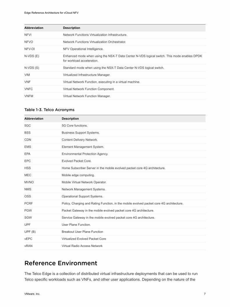
Acronyms and DefinitionsVMware Telco Edge Architecture uses a specific set of abbreviations that apply to the NFV technologyand the Telco industry.
Table 1-1. General Acronyms
Abbreviation Description
AR Augmented Reality
BFD Bidirectional Forwarding Detection, for failure detection on the transport links.
CPF Control Plane Functions
IoT Internet of Things
MTTU Mean Time to Understand.
MTTR Mean Time to Repair.
VR Virtual Reality
UPF User Plane Functions
Table 1-2. NFV Acronyms
Abbreviation Description
CCP Centralized Control Plane in the NSX-T Data Center architecture.--
CNF Container Network Function, executing within a Kubernetes environment.
LCP Local Control Plane r in the NSX-T Data Center architecture.
LIF Logical Interfaces
MANO Management and Orchestration components, a term originating from the ETSI NFV architectureframework.
Edge Reference Architecture for vCloud NFV
VMware, Inc. 6
Abbreviation Description
NFVI Network Functions Virtualization Infrastructure.
NFVO Network Functions Virtualization Orchestrator.
NFV-OI NFV Operational Intelligence.
N-VDS (E) Enhanced mode when using the NSX-T Data Center N-VDS logical switch. This mode enables DPDKfor workload acceleration.
N-VDS (S) Standard mode when using the NSX-T Data Center N-VDS logical switch.
VIM Virtualized Infrastructure Manager.
VNF Virtual Network Function, executing in a virtual machine.
VNFC Virtual Network Function Component.
VNFM Virtual Network Function Manager.
Table 1-3. Telco Acronyms
Abbreviation Description
5GC 5G Core functions.
BSS Business Support Systems.
CDN Content Delivery Network.
EMS Element Management System.
EPA Environmental Protection Agency.
EPC Evolved Packet Core.
HSS Home Subscriber Server in the mobile evolved packet core 4G architecture.
MEC Mobile edge computing.
MVNO Mobile Virtual Network Operator.
NMS Network Management Systems.
OSS Operational Support Systems.
PCRF Policy, Charging and Rating Function, in the mobile evolved packet core 4G architecture.
PGW Packet Gateway in the mobile evolved packet core 4G architecture.
SGW Service Gateway in the mobile evolved packet core 4G architecture.
UPF User Plane Function.
UPF (B) Breakout User Plane Function
vEPC Virtualized Evolved Packet Core
vRAN Virtual Radio Access Network
Reference EnvironmentThe Telco Edge is a collection of distributed virtual infrastructure deployments that can be used to runTelco specific workloads such as VNFs, and other user applications. Depending on the nature of the
Edge Reference Architecture for vCloud NFV
VMware, Inc. 7

workloads and applications, the position in the network, the size of the deployment, and the softwaredefined infrastructure model, this Edge Reference Architecture provides the desired flexibility.
The mobile network is also transforming into a mixture of highly distributed network functions coupled withsome centralized control plane and management plane functions. 5G services are typically comprised ofa mixture of low-latency, high throughput, and high user density applications. This requires deployment ofboth applications and network functions at the edge. The implication for the Telco network is that itevolves from a purely centralized model of service delivery to a highly distributed one. There is also anemerging paradigm shift with employing third-party IaaS, PaaS, and SaaS offerings from public cloudproviders. These changes essentially require a more sophisticated service delivery model.
The following diagram shows the reference environment for a Telco network with the addition of edgeswith clear functional abstractions and interactions in a tiered approach.
Figure 1-1. Reference Environment
VM VM VM VM VM VM VM VM VM
Internet Internet
Hub
Customer Edge (Millions)
40-80 µs <1-5 ms <5-10 ms <20-50 ms
1-3 Servers 5-10 Servers 1-5 Racks Multiple Racks
SD-WAN uCPE
vRAN AR/VR Gaming
vEPC UP MEC
Video Surveillance CDN
IoT Apps
vEPC CP vIMS
5G CP Subscriber (HSS)
Policy (PCRF)
Far Edge (1000’s)
NearEdge (100’s)
Core (10’s)
Slices
Central Office
Central/ Regional
Internet
Customer EdgeOn the left of the reference environment in the preceding figure is the customer edge, which comprisesmillions of end-points (especially with the requirements for IoT). The Customer Edge is on customerpremises or it may be a wireless device. The capacity and capability of the customer edge depends onthe use cases. SD-WAN is a usecase for such Customer Edges and other services, such as virtualfirewalls, and so on. The Customer Edge is not discussed in this Reference Architecture.
Edge Reference Architecture for vCloud NFV
VMware, Inc. 8
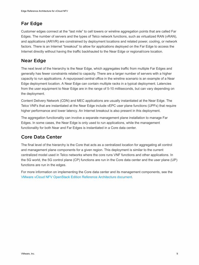
Far EdgeCustomer edges connect at the “last mile” to cell towers or wireline aggregation points that are called FarEdges. The number of servers and the types of Telco network functions, such as virtualized RAN (vRAN),and applications (AR/VR) are constrained by deployment locations and related power, cooling, or networkfactors. There is an Internet “breakout” to allow for applications deployed on the Far Edge to access theInternet directly without having the traffic backhauled to the Near Edge or regional/core location.
Near EdgeThe next level of the hierarchy is the Near Edge, which aggregates traffic from multiple Far Edges andgenerally has fewer constraints related to capacity. There are a larger number of servers with a highercapacity to run applications. A repurposed central office in the wireline scenario is an example of a NearEdge deployment location. A Near Edge can contain multiple racks in a typical deployment. Latenciesfrom the user equipment to Near Edge are in the range of 5-10 milliseconds, but can vary depending onthe deployment.
Content Delivery Network (CDN) and MEC applications are usually instantiated at the Near Edge. TheTelco VNFs that are instantiated at the Near Edge include vEPC user plane functions (UPFs) that requirehigher performance and lower latency. An Internet breakout is also present in this deployment.
The aggregation functionality can involve a separate management plane installation to manage FarEdges. In some cases, the Near Edge is only used to run applications, while the managementfunctionality for both Near and Far Edges is instantiated in a Core data center.
Core Data CenterThe final level of the hierarchy is the Core that acts as a centralized location for aggregating all controland management plane components for a given region. This deployment is similar to the currentcentralized model used in Telco networks where the core runs VNF functions and other applications. Inthe 5G world, the 5G control plane (CP) functions are run in the Core data center and the user plane (UP)functions are run in the edges.
For more information on implementing the Core data center and its management components, see theVMware vCloud NFV OpenStack Edition Reference Architecture document.
Edge Reference Architecture for vCloud NFV
VMware, Inc. 9
Reference Environment Requirements for EdgeThe edge infrastructure reference environment places strict requirements for service placement andmanagement to achieve optimal performance.
Federation options The reference environment topology offers a diverse set of federationoptions for end-points, private and public clouds, each with distinctownership and management domains.
Disaggregatedfunctions
Services are highly disaggregated so that control, data, and managementplanes can be deployed across the distributed topology. Edge clouds offerperformance advantages of low latency to allow for data plane intensiveworkloads while control and management plane components can becentralized with a regional and global scope.
Functional isolation With the ability to isolate tenants and providing them with their ownresource slices, the reference environment allows for network and serviceisolation. However, resource management decisions are to be made forshared network functions such as DNS, policy, authentication, and so on.Another facet of 5G technology is the ability to carve an independent sliceof the end-to-end mobile network to specific use or enterprise. Each slicehas its own end-to-end logical network that includes guarantees, dedicatedmobile core elements such as 5G CPF/UPF, and enterprise-specific Telconetworking. While the virtual assets are created in the same Telco Cloudinfrastructure, it is the responsibility of the Virtualization Infrastructure toprovide thecomplete resource isolation with a guarantee for each networkslice. This includes compute, network, and storage resource guarantees.
Service placement The highly distributed topology allows for flexibility in the workloadplacement. Making decisions based on proximity, locality, latency, analyticalintelligence, and other EPA criteria are critical to enable an intent-basedplacement model.
Workload life cyclemanagement
Each cloud is elastic with workload mobility and how applications aredeployed, executed, and scaled. An integrated operations managementsolution can enable an efficient life cycle management to ensure servicedelivery and QoS.
Carrier gradecharacteristics
CSPs deliver services that are often regulated by local governments.Hence, carrier grade aspects of these services, such as high availabilityand deterministic performance, are also important.
NFVI life cycle(patching andupgrades)
The platform must be patched and upgraded by using optimized changemanagement approaches for zero to minimal downtime.
Edge Reference Architecture for vCloud NFV
VMware, Inc. 10

Telco Edge Conceptual ArchitectureA classic 3-layer conceptual architecture for the Telco Edge deployment is a hierarchical model thatconsists of a group of Far Edge sites that aggregate into a Near Edge site and a group of Near Edge sitesthat aggregate into a Core site.
Figure 1-2. Telco Edge Conceptual Architecture
Internet
Internet
Internet Internet
Far Edge Far Edge
Region 1 Region N
Far Edge Far Edge Far Edge
Internet Internet Internet
Internet
Core Data Center
Near Edge Near Edge
The maximum number of Edge sites in a specific group is governed by the maximum scale supported bythe respective management components. In addition to functioning as a traffic aggregation point, a higherlayer site also functions as a management layer for the lower tiers, as appropriate. Therefore, themanagement component for all the Far Edge sites aggregating into a Near Edge is usually located in thespecific Near Edge site. But, the management component for the Near Edge site can be located locallyfor expediency reasons.
Each of the Edge sites is individually addressable and the workloads can be placed in the correct Edgesite. Each Edge site also has a local breakout capability to the Internet. Therefore, Internet bound trafficdoes not have to traverse through the Telco network before being routed to its destination.
Telco Edge Reference ModelTo optimize the Edge deployment to run workloads without significant management overhead, themanagement plane functionality for the Edges is usually implemented in a site remote to the Edge. Whilethis imposes some constraints on networking (including link availability and end-to-end latency), thismodel of remote management is useful for constrained environments such as Far Edges.
The benefit of this model is the ease and simplicity with which the entire Telco infrastructure can beadministered. Instead of having to connect to each Edge site to configure and control the resources atthat site, users can access the centralized management at the Core data center, which can give themaccess to all the Edge sites under its purview.
Edge Reference Architecture for vCloud NFV
VMware, Inc. 11
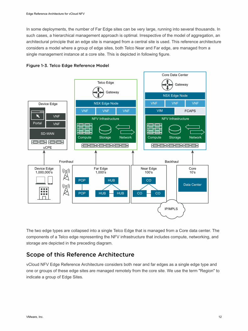
In some deployments, the number of Far Edge sites can be very large, running into several thousands. Insuch cases, a hierarchical management approach is optimal. Irrespective of the model of aggregation, anarchitectural principle that an edge site is managed from a central site is used. This reference architectureconsiders a model where a group of edge sites, both Telco Near and Far edge, are managed from asingle management instance at a core site. This is depicted in following figure.
Figure 1-3. Telco Edge Reference Model
Device Edge
Portal
VNF
VNF
SD-WAN
uCPE
Telco Edge
Device Edge1,000,000’s
Far Edge1,000’s
Near Edge100’s
Core 10’s
Gateway
VNF VNF VNF
NSX Edge Node VNF VNF VNF
NSX Edge Node
POP
POP
HUB
HUB HUB
CO
CO CO
Data Center
Core Data Center
Gateway
VIM FCAPS
Fronthaul Backhaul
IP/MPLS
Compute Storage Network
NFV Infrastructure
Compute Storage Network
NFV Infrastructure
The two edge types are collapsed into a single Telco Edge that is managed from a Core data center. Thecomponents of a Telco edge representing the NFV infrastructure that includes compute, networking, andstorage are depicted in the preceding diagram.
Scope of this Reference ArchitecturevCloud NFV Edge Reference Architecture considers both near and far edges as a single edge type andone or groups of these edge sites are managed remotely from the core site. We use the term "Region" toindicate a group of Edge Sites.
Edge Reference Architecture for vCloud NFV
VMware, Inc. 12

The Core site is connected to the Edge site through a Telco network generically described as metro/WANin this reference architecture. Examples of such networks include Metro Ethernet, MPLS and so on.However, the actual technology used is not pertinent to this reference architecture. Because the coresites and the edge sites are connected over Layer 3, it is important that a routed network topology existsbetween the sites.
Layer 2 networks are expected to be terminated at the provider Edge (PE) routers at the Core and at theEdge data centers. A Layer 3 path and connection between the core PE router and the Edge PE routerthrough the metro or WAN network is assumed to be configured beforehand. It is important to ensure thata sufficient bandwidth at low latency is available for the Core site and Edge site connectivity.
Edge Reference Architecture for vCloud NFV
VMware, Inc. 13
Architectural Framework andComponents 2The overall framework of the VMware vCloud NFV Telco Edge Architecture includes the key stakeholders,conceptual architecture environment, logical architecture, and components of the platform.
This chapter includes the following topics:
n Key Stakeholders
n Logical Architecture and Components
n NFV OpenStack Edition Components
n Design Principles
Key StakeholdersThe reference architecture considers key stakeholders that are involved in the end-to-end servicemanagement, life cycle management, and operations of the infrastructure and the applications running onit.
Cloud provider The CSP operations personnel who are responsible for provisioning andon-boarding all day 0 and day 1 functions to enable services for targetcustomers and tenants.
Consumer The end user who is consuming the services that the tenants provide. Forexample, IoT devices, mobile handsets, API consumers, and MVNO.
Customer The enterprise or entity who owns the business relationship with the CSP.The customer might be an internal line of business such as fixed line andmobile services and can also be an external enterprise.
Tenant A tenant represents a logical separation of the entity housed on andconsuming infrastructure services to a provide a service. This may be aspecific subset of customers for the Telco, an MVNO (Mobile VirtualNetwork Operator) which operates on top of the Telco infrastructure toprovide their own virtual network, or a VNF vendor which provides aspecific capability and so on. Each tenant is represented as a resourceslice. Key resources that can be packaged in a resource slice are mobilenetwork bandwidth, specific services enabled, number of subscribers, andso on.
VMware, Inc. 14

Operations Support The operations management process and team that ensure the servicesare operating to meet the promised stringent SLAs.
System Planning The operations management planning function that is responsible for theresource and VNF capacity and forecasting and new data center designs.
Security Operations Security operations function that is responsible for all aspects of security,network, application, and data.
Logical Architecture and ComponentsThe vCloud NFV Edge reference architecture implements the conceptual architecture that is outlined anddefined at a high level through the logical building blocks and core components. The following diagrammaps the conceptual architecture to a logical view for the vCloud NFV Edge reference architecture.
Figure 2-1. Logical Architecture
Core Management Domain Region 1 Edge Management Domain Region n Edge Management Domain
Compute Domain
Core Data Center NFVI
Compute Domain
Edge Site 1
Edge Site 2
Edge Site n
Edge Data Center NFVI
Compute Domain
Edge Site 1
Edge Site 2
Edge Site n
Edge Data Center NFVI
Operations Management and AnalyticsOperations Management and Analytics
Core Data Center
Telco Network
Core Data CenterThe Core data center is used to house the management components and other NFV functions that needto run at a central location. In the context of this reference architecture, a Core Data Center continues torun the core NFVi functions while also hosting the management components to manage the various telcoedge sites.
Physical ConfigurationThe Core site follows the three-pod design used in the vCloud NFV 3.x Reference Architecture andincludes a minimum of three hosts (four recommended) in the management pod and the Edge pods. Theresource pods comprise the hosts in the remote sites and any local clusters related to operations andfunctionality of the Edge sites.
Edge Reference Architecture for vCloud NFV
VMware, Inc. 15
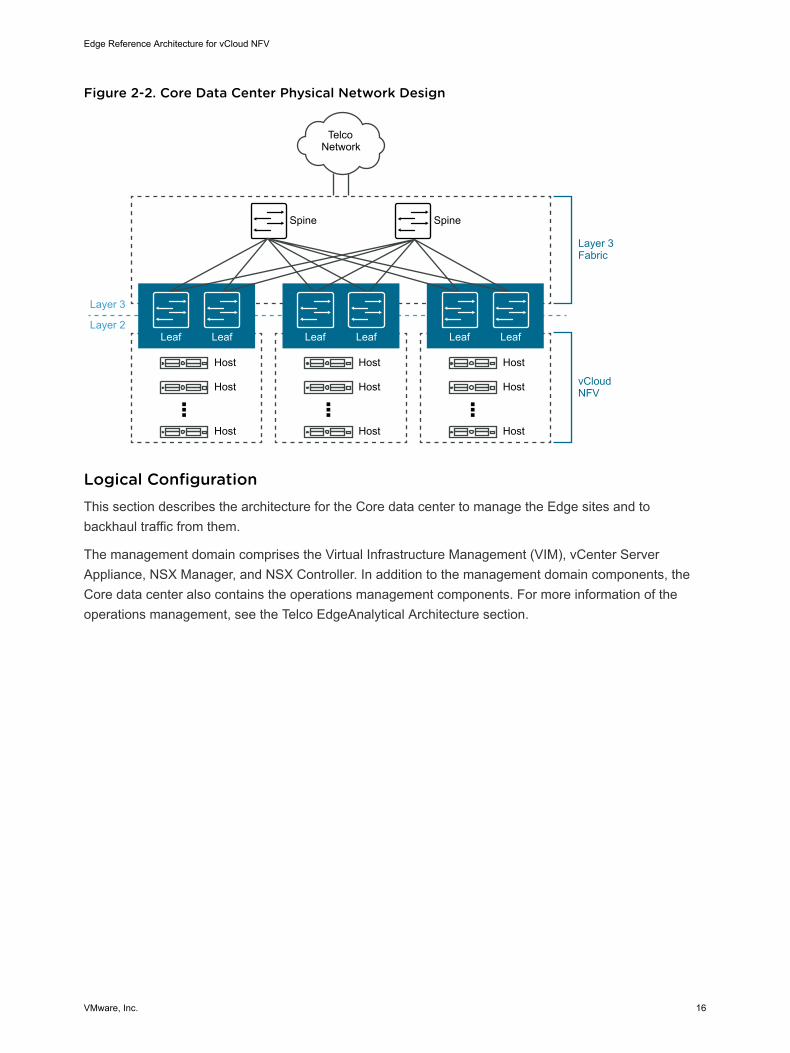
Figure 2-2. Core Data Center Physical Network Design
Telco Network
Host
Spine Spine
Layer 3
Layer 3 Fabric
vCloud NFV
Layer 2
Host
Host
Leaf Leaf
Host
Host
Host
Leaf Leaf
Host
Host
Host
Leaf Leaf
Logical ConfigurationThis section describes the architecture for the Core data center to manage the Edge sites and tobackhaul traffic from them.
The management domain comprises the Virtual Infrastructure Management (VIM), vCenter ServerAppliance, NSX Manager, and NSX Controller. In addition to the management domain components, theCore data center also contains the operations management components. For more information of theoperations management, see the Telco EdgeAnalytical Architecture section.
Edge Reference Architecture for vCloud NFV
VMware, Inc. 16
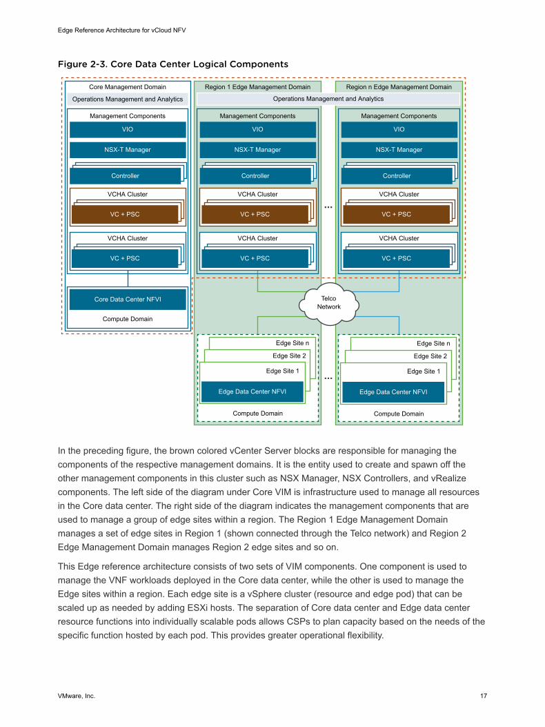
Figure 2-3. Core Data Center Logical Components
Core Management Domain
Management Components
NSX-T Manager
Controller
VC + PSC
VCHA Cluster
Region 1 Edge Management Domain
Management Components
Region n Edge Management Domain
Management Components
VC + PSC
VCHA Cluster
Telco Network
Compute Domain
Core Data Center NFVI
NSX-T Manager
Controller
VC + PSC
VCHA Cluster
VC + PSC
VCHA Cluster
NSX-T Manager
VIO VIO VIO
Controller
VC + PSC
VCHA Cluster
VC + PSC
VCHA Cluster
Compute Domain
Edge Site 1
Edge Site 2
Edge Site n
Edge Data Center NFVI
Compute Domain
Edge Site 1
Edge Site 2
Edge Site n
Edge Data Center NFVI
Operations Management and AnalyticsOperations Management and Analytics
In the preceding figure, the brown colored vCenter Server blocks are responsible for managing thecomponents of the respective management domains. It is the entity used to create and spawn off theother management components in this cluster such as NSX Manager, NSX Controllers, and vRealizecomponents. The left side of the diagram under Core VIM is infrastructure used to manage all resourcesin the Core data center. The right side of the diagram indicates the management components that areused to manage a group of edge sites within a region. The Region 1 Edge Management Domainmanages a set of edge sites in Region 1 (shown connected through the Telco network) and Region 2Edge Management Domain manages Region 2 edge sites and so on.
This Edge reference architecture consists of two sets of VIM components. One component is used tomanage the VNF workloads deployed in the Core data center, while the other is used to manage theEdge sites within a region. Each edge site is a vSphere cluster (resource and edge pod) that can bescaled up as needed by adding ESXi hosts. The separation of Core data center and Edge data centerresource functions into individually scalable pods allows CSPs to plan capacity based on the needs of thespecific function hosted by each pod. This provides greater operational flexibility.
Edge Reference Architecture for vCloud NFV
VMware, Inc. 17
For best practices when using vSAN as the shared storage solution for the Core data center, initialdeployment requires a minimum of four hosts per cluster. This sizing recommendation provides balancebetween the implementation footprint and resiliency, while maintaining the operational requirementsnecessary for the site.
The Resource and Edge clusters at each site are sized in accordance with the VNFs and their respectivenetworking requirements. CSPs must work with the VNF vendors to gather requirements for the VNFservice to be deployed. This information is typically available in deployment guides and sizing guidelinedocuments.
The number of remote sites under a single Region can vary depending upon the size of the Edge sitesand the number of local clusters in the resource pod. For detailed configuration maximums click here.
Telco EdgeThe Telco Edge is the site that houses the remote workloads (VNFs and applications). It consists of NSXEdge and VNF workloads in a compute domain. The compute domain maps to a vSphere clustermanaged by the vCenter Server from the Core data center. The number of edge servers at a remote sitedepends on the workload to run. Two servers are used to host the NSX Edge Node VMs that forwardtraffic from the logical network to the physical network in a north south direction through the edge routerand to the metro/WAN network connecting the edge and core sites.
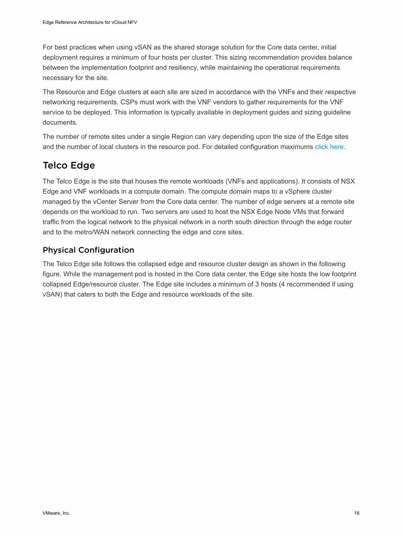
Physical ConfigurationThe Telco Edge site follows the collapsed edge and resource cluster design as shown in the followingfigure. While the management pod is hosted in the Core data center, the Edge site hosts the low footprintcollapsed Edge/resource cluster. The Edge site includes a minimum of 3 hosts (4 recommended if usingvSAN) that caters to both the Edge and resource workloads of the site.
Edge Reference Architecture for vCloud NFV
VMware, Inc. 18
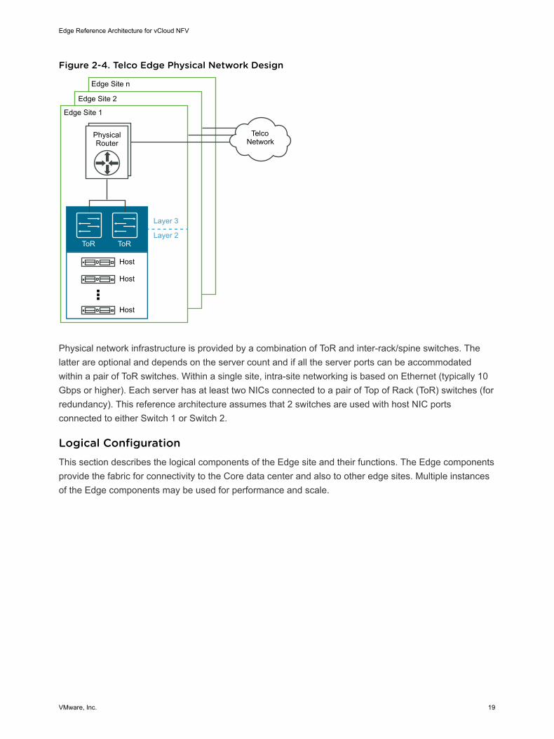
Figure 2-4. Telco Edge Physical Network Design
Telco Network
Host
Layer 3
Edge Site 1
Edge Site 2
Edge Site n
Physical Router
Layer 2
Host
Host
ToR ToR
Physical network infrastructure is provided by a combination of ToR and inter-rack/spine switches. Thelatter are optional and depends on the server count and if all the server ports can be accommodatedwithin a pair of ToR switches. Within a single site, intra-site networking is based on Ethernet (typically 10Gbps or higher). Each server has at least two NICs connected to a pair of Top of Rack (ToR) switches (forredundancy). This reference architecture assumes that 2 switches are used with host NIC portsconnected to either Switch 1 or Switch 2.
Logical ConfigurationThis section describes the logical components of the Edge site and their functions. The Edge componentsprovide the fabric for connectivity to the Core data center and also to other edge sites. Multiple instancesof the Edge components may be used for performance and scale.
Edge Reference Architecture for vCloud NFV
VMware, Inc. 19
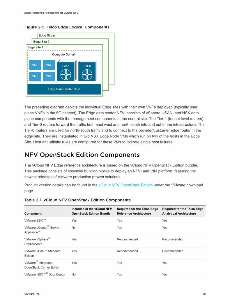
Figure 2-5. Telco Edge Logical Components
Edge Site 1
Compute Domain
Edge Site 2
Edge Site n
Tier-1
Edge Data Center NFVI
VNF
VNF
VNF
VNF
Tier-0
The preceding diagram depicts the individual Edge sites with their own VNFs deployed (typically userplane VNFs in the 5G context). The Edge data center NFVI consists of vSphere, vSAN, and NSX dataplane components with the management components at the central site. The Tier-1 (tenant level routers)and Tier-0 routers forward the traffic both east west and north south into and out of the infrastructure. TheTier-0 routers are used for north-south traffic and to connect to the provider/customer edge router in theedge site. They are instantiated in two NSX Edge Node VMs which run on two of the hosts in the EdgeSite. Host anti-affinity rules are configured for these VMs to tolerate single host failures.
NFV OpenStack Edition ComponentsThe vCloud NFV Edge reference architecture is based on the vCloud NFV OpenStack Edition bundle.This package consists of essential building blocks to deploy an NFVI and VIM platform, featuring thenewest releases of VMware production proven solutions.
Product version details can be found in the vCloud NFV OpenStack Edition under the VMware downloadpage.
Table 2-1. vCloud NFV OpenStack Edition Components
ComponentIncluded in the vCloud NFVOpenStack Edition Bundle
Required for the Telco EdgeReference Architecture
Required for the Telco EdgeAnalytical Architecture
VMware ESXi™ Yes Yes Yes
VMware vCenter® ServerAppliance™
No Yes Yes
VMware vSphere®
Replication™Yes Recommended Recommended
VMware vSAN™ StandardEdition
Yes Recommended Recommended
VMware® IntegratedOpenStack Carrier Edition
Yes Yes Yes
VMware NSX-T® Data Center No Yes Yes
Edge Reference Architecture for vCloud NFV
VMware, Inc. 20

ComponentIncluded in the vCloud NFVOpenStack Edition Bundle
Required for the Telco EdgeReference Architecture
Required for the Telco EdgeAnalytical Architecture
VMware Site RecoveryManager™
No Recommended Recommended
VMware vRealize®
Operations™Yes No Yes
VMware vRealize® LogInsight™
Yes No Yes
VMware vRealize®
OrchestratorYes No Yes
VMware vRealize® NetworkInsight™
No No Recommended
Design PrinciplesThe following design principles communicate a summary of the details that form the basis for the vCloudNFV Edge reference architecture using vCloud NFV components.
Deployment FlexibilityStarting with a low management overhead at the Edge sites, the architecture provides flexibility forincluding a two vSphere cluster configuration (separate compute cluster and Edge cluster) at Edge sitesrequiring higher performance with NSX Edge Nodes. In cases where the number of compute nodes at theEdge site are limited, it possible to have a combined compute and Edge cluster where the NSX EdgeNodes run as VMs on the same compute cluster as the workloads
Multi Tenancy and Advanced NetworkingWithin an Edge site, it is possible to house one or more tenants managed from the regional or core datacenter. This is realized using the multi-tenant capabilities of NSX-T (T1 and T0 routers) and theintegration with VMware Integrated OpenStack (VIO).
Workload AccelerationTo run user plane functions requiring lower latency and higher throughput at the Edge sites, the N-VDS(Enhanced) virtual switch can be configured on the hosts where these functions are to run. The UPF VMscan then be configured to run on top of the N-VDS (Enhanced) switch.
Real-time Integrated Operational IntelligenceBy using a framework that continuously collects data from local and distributed agents, vCloud NFV EdgeReference Architecture provides the capability to correlate, analyze, and enable day 2 operations. Thisanalytics engine can be used with existing assurance engines for closed-loop. In addition, this analyticsengine can be deployed in a distributed fashion in near-Edge sites towards smarter WAN bandwidthmanagement and real-time closed-loop assurance.
Edge Reference Architecture for vCloud NFV
VMware, Inc. 21
Orchestration IntegrationvCloud NFV OpenStack Edition provides the flexibility to integrate the distributed managementcomponents, such as VIMs, with open-source-based Orchestrators such as ONAP, OSM, and third-partyOrchestrators using industry standard interfaces.
Edge Reference Architecture for vCloud NFV
VMware, Inc. 22
Telco Edge ReferenceArchitecture 3The vCloud NFV Edge reference architecture implements the conceptual architecture that is outlined anddefined at a high level through the logical building blocks and core components.
This chapter includes the following topics:
n Telco Edge Logical Building Blocks
n Telco Edge Virtual Building Blocks
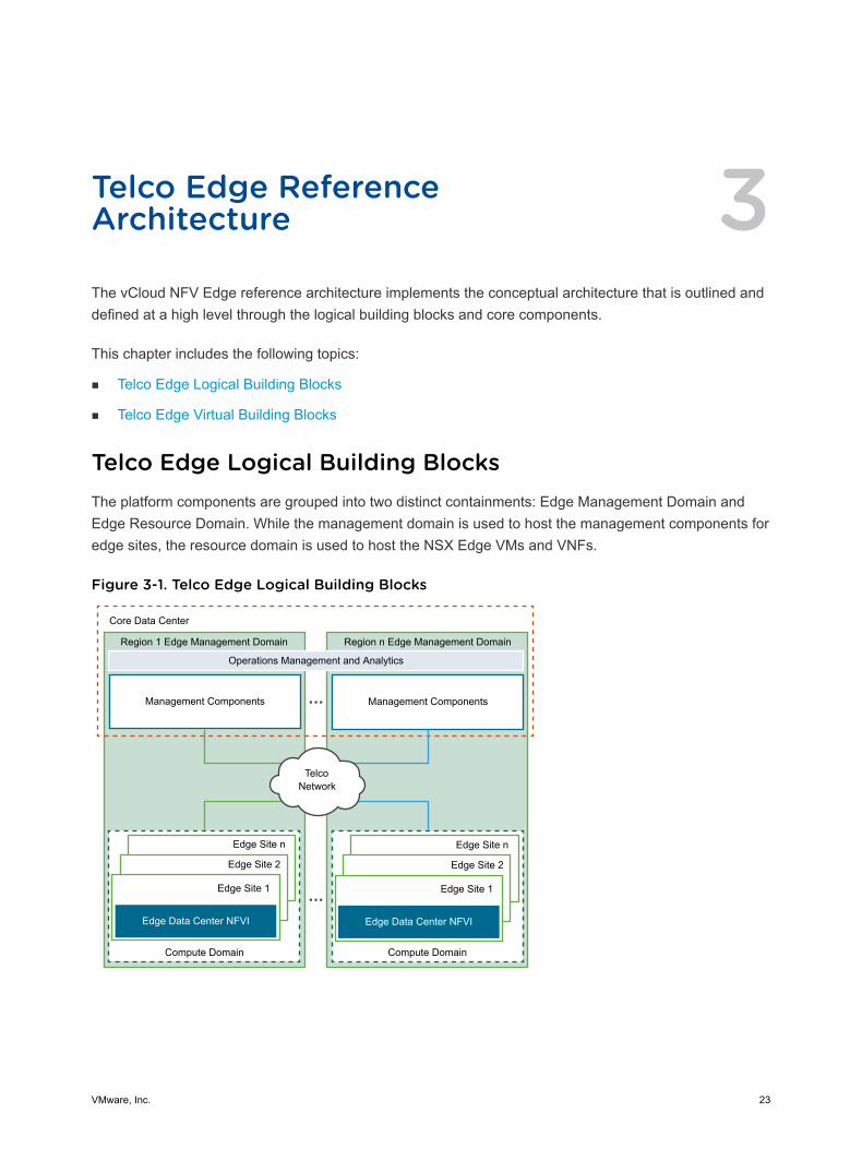
Telco Edge Logical Building BlocksThe platform components are grouped into two distinct containments: Edge Management Domain andEdge Resource Domain. While the management domain is used to host the management components foredge sites, the resource domain is used to host the NSX Edge VMs and VNFs.
Figure 3-1. Telco Edge Logical Building Blocks
Region 1 Edge Management Domain Region n Edge Management Domain
Compute Domain Compute Domain
Edge Site 1
Edge Site 2
Edge Site n
Edge Data Center NFVI
Edge Site 1
Edge Site 2
Edge Site n
Edge Data Center NFVI
Operations Management and Analytics
Management Components Management Components
Core Data Center
Telco Network
VMware, Inc. 23
The preceding figure shows the building blocks for the edge. An Edge data center is mapped to an edgesite. Edge sites (or Edge data centers) are grouped into regions and they have a corresponding instanceof VIO deployed in the Core data center. The operations management and analytics components overseethe edge management instances. This section describes the physical and logical configuration of theedge building blocks.
Telco EdgeManagement Domain
An Edge site follows the collapsed edge/resource pod design used in thevCloud NFV 3.1 reference architecture. This design entails a minimum ofthree servers (four recommended if using vSAN) to provide pooledcompute resources to both the VNF workloads deployed at the site and tothe NSX-T Data Center edge nodes.
The edge storage may be provided by any supported shared storagesolution. This reference architecture uses vSAN as the storage provider.
Each server must have local disks for vSAN caching and capacity tiers. AnAll Flash vSAN is recommended for reliability and performance.
Each physical host must have a minimum of six physical NICs connected toa pair of ToR switches in a LAG configuration for redundancy. The pairing ofthe physical NICs and their distribution across the virtual switches iscovered in later sections. The ToR switches connect to an external WANEdge physical router to transport packets for Internet breakout andbackhaul to the Core site.
Telco Edge ComputeDomain
Logically an edge site is a separate vSphere/vSAN cluster with hostsconnecting to and managed by the vCenter Server that is a part of themanagement instance for the corresponding region. This edge cluster musthost both the VNF workloads and the NSX-T Data Center edge nodes, andit must be sized accordingly.
The number of edge sites within a region are constrained by theconfiguration maximums of the management components for that region.When the maximum limit is reached, a new management instance isdeployed to accommodate the growth.
The actual sizing depends on factors influenced by the inter-dependenciesbetween management components and their configuration limits. Forexample, a single NSX-T Data Center 2.3 installation can manage amaximum of 768 hosts as the limiting factor, whereas a single vCenterServer 6.7 can manage up to 2000 hosts. The actual number of supportedsites vary depending on the sizing of each site. All the edge sites need notbe sized equally, but are sized based on their respective workloadrequirements.
Edge Reference Architecture for vCloud NFV
VMware, Inc. 24
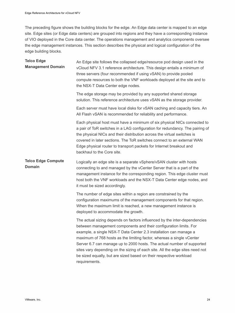
Telco Edge Virtual Building BlocksThe virtual infrastructure design comprises the design of the software components that form the virtualinfrastructure layer. This layer supports running Telco workloads and workloads that maintain thebusiness continuity of services. The virtual infrastructure components include the virtualization platformhypervisor, virtualization management, storage virtualization, network virtualization, and backup anddisaster recovery components.
This section outlines the building blocks for the virtual infrastructure, their components, and thenetworking to tie all the components together.
Figure 3-2. Telco Edge Virtual Building Blocks
Core Data Center
Operations Management and Analytics
VIO
NSX-T Manager
Controller
VC + PSC
VCHA Cluster
VC + PSC
VCHA Cluster
Region 1 Edge Management Domain
Region n Edge Management Domain
Edge Site 1
Telco Router
Telco Router
T0 (VM)
ESXiESXiESXi
Edge Site 2
Telco Router
T0 (VM)
ESXiESXiESXi
Edge Site n
Telco Router
T0 (VM)
ESXiESXiESXi
Telco Network
Edge Reference Architecture for vCloud NFV
VMware, Inc. 25

Compute DesignIt is important to limit the distance between the core site and the edge sites to ensure that the latency isbelow 150 ms RTT. In addition, each site is treated as a remote cluster with its own storage – HCI storagewith vSAN is recommended. An NSX Edge (pair) needs to be deployed at the remote site (even thoughthe NSX Manager and Controller resides at the Core site) for connectivity to the Core site and for Internetbreakout.
The network links between the core site and the edge sites should also be redundant and path-diversewithout any SRLGs (Shared Risk Link Groups) between the paths at a transport layer. In addition, aminimum bandwidth of 10Gbps is required between each edge site and the core site.
Storage DesignThis section outlines the building blocks for the virtual infrastructure shared storage design that is basedon vSAN. vCloud NFV OpenStack Edition also supports certified third-party shared storage solutions, aslisted in the VMware Compatibility Guide.
vSAN is a software feature built into the ESXi hypervisor that allows locally attached storage to be pooledand presented as a shared storage pool for all hosts in a vSphere cluster. This simplifies the storageconfiguration with a single datastore per cluster for management and VNF workloads. With vSAN, VMdata is stored as objects and components. One object consists of multiple components that aredistributed across the vSAN cluster based on the policy that is assigned to the object. The policy for theobject ensures a highly available storage backend for the cluster workload, with no single point of failure.
vSAN is a fully integrated hyper-converged storage software. Creating a cluster of server hard disk drives(HDDs) or solid-state drives (SSDs), vSAN presents a flash-optimized, highly resilient, shared storagedatastore to ESXi hosts and virtual machines. This allows for the control of capacity, performance, andavailability through storage policies, on a per VM basis.
Network DesignThe vCloud NFV Edge platform consists of infrastructure networks and VM networks. Infrastructurenetworks are host level networks that connect hypervisors to physical networks. Each ESXi host hasmultiple port groups configured for each infrastructure network.
The hosts in each cluster are configured with VMware vSphere® Distributed Switch™ (vDS) devices thatprovide consistent network configuration across multiple hosts. One vSphere Distributed Switch is usedfor VM networks and the other one maintains the infrastructure networks. Also, the N-VDS switch is usedas the transport for Telco workload traffic.
Edge Reference Architecture for vCloud NFV
VMware, Inc. 26
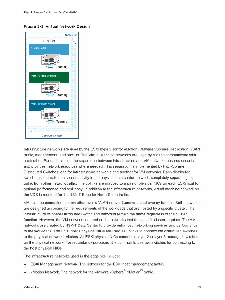
Figure 3-3. Virtual Network Design
Edge Site
Compute Domain
VDS (Virtual Machine)
VDS (Infrastructure)
ESXi Host
N-VDS (E/S)
Teaming
Teaming
Teaming
Infrastructure networks are used by the ESXi hypervisor for vMotion, VMware vSphere Replication, vSANtraffic, management, and backup. The Virtual Machine networks are used by VMs to communicate witheach other. For each cluster, the separation between infrastructure and VM networks ensures securityand provides network resources where needed. This separation is implemented by two vSphereDistributed Switches, one for infrastructure networks and another for VM networks. Each distributedswitch has separate uplink connectivity to the physical data center network, completely separating itstraffic from other network traffic. The uplinks are mapped to a pair of physical NICs on each ESXi host foroptimal performance and resiliency. In addition to the infrastructure networks, virtual machine network onthe VDS is required for the NSX-T Edge for North-South traffic.
VMs can be connected to each other over a VLAN or over Geneve-based overlay tunnels. Both networksare designed according to the requirements of the workloads that are hosted by a specific cluster. Theinfrastructure vSphere Distributed Switch and networks remain the same regardless of the clusterfunction. However, the VM networks depend on the networks that the specific cluster requires. The VMnetworks are created by NSX-T Data Center to provide enhanced networking services and performanceto the workloads. The ESXi host’s physical NICs are used as uplinks to connect the distributed switchesto the physical network switches. All ESXi physical NICs connect to layer 2 or layer 3 managed switcheson the physical network. For redundancy purposes, it is common to use two switches for connecting tothe host physical NICs.
The infrastructure networks used in the edge site include:
n ESXi Management Network. The network for the ESXi host management traffic.
n vMotion Network. The network for the VMware vSphere® vMotion® traffic.
Edge Reference Architecture for vCloud NFV
VMware, Inc. 27

n vSAN Network. The network for the vSAN shared storage traffic.
Telco Edge Management DomainTelco Edge Management Domain includes Virtualized Infrastructure Management (VIM) components suchas vCenter Server Appliance, NSX Manager, and VMware Integrated OpenStack.
Figure 3-4. Telco Edge Management Domain
VMware Integrated OpenStack
vCenter Server +Platform Services
ControllerNSX-T Manager
Edge Management Domain
NSX ControllervCenter Server +Platform Services
Controller
Management Network
In addition to these components, the Management Domain also contains the operations managementcomponents. For more information, see the Chapter 5 Telco Edge Analytical Architecture section.
Telco Edge Management Domain ComponentsThe Management domain contains the components that manage the Edge Region runtime environment.This domain includes VMware Integrated OpenStack(VIM), vCenter Server, NSX Manager and itscomponents.
vCenter Server
The Edge Management domain is implemented as a cluster that is managed by the brown vCenterServer instance shown in preceding figure. To form the foundation of a carrier grade virtualizedinfrastructure, the components of the Management Domain benefit from the cluster features such asresource management, high availability, and resiliency. A second vCenter Server is deployed in theManagement Domain to oversee the Edge Compute Domain for the respective region.
Each vCenter Server instance is a virtual appliance that is deployed with an embedded database. ThevCenter® Server Appliance™ is preconfigured, hardened, and fast to deploy. The appliance allows for asimplified design, eases management, and reduces administrative efforts. vCenter Server Applianceavailability is ensured by using a vCenter High Availability (vCenter HA) cluster, which is realized throughthree vCenter Server Appliance instances. The vCenter HA cluster consists of one active node thatserves client requests, one passive node as a backup in the event of failure, and one quorum node that iscalled a witness node. Replication between nodes using a dedicated vCenter HA network ensures thatvCenter Server Appliance data is always synchronized and up-to-date.
Edge Reference Architecture for vCloud NFV
VMware, Inc. 28
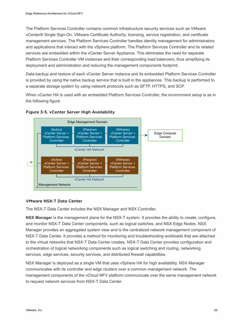
The Platform Services Controller contains common infrastructure security services such as VMwarevCenter® Single Sign-On, VMware Certificate Authority, licensing, service registration, and certificatemanagement services. The Platform Services Controller handles identity management for administratorsand applications that interact with the vSphere platform. The Platform Services Controller and its relatedservices are embedded within the vCenter Server Appliance. This eliminates the need for separatePlatform Services Controller VM instances and their corresponding load balancers, thus simplifying itsdeployment and administration and reducing the management components footprint.
Data backup and restore of each vCenter Server instance and its embedded Platform Services Controlleris provided by using the native backup service that is built in the appliances. This backup is performed toa separate storage system by using network protocols such as SFTP, HTTPS, and SCP.
When vCenter HA is used with an embedded Platform Services Controller, the environment setup is as inthe following figure.
Figure 3-5. vCenter Server High Availability
Edge Management Domain
vCenter HA NetworkManagement Network
vCenter HA Network
Edge Compute Domain
(Active) vCenter Server +Platform Services
Controller
(Passive) vCenter Server +Platform Services
Controller
(Witness) vCenter Server +Platform Services
Controller
(Active) vCenter Server +Platform Services
Controller
(Passive) vCenter Server +Platform Services
Controller
(Witness) vCenter Server +Platform Services
Controller
VMware NSX-T Data Center
The NSX-T Data Center includes the NSX Manager and NSX Controller.
NSX Manager is the management plane for the NSX-T system. It provides the ability to create, configure,and monitor NSX-T Data Center components, such as logical switches, and NSX Edge Nodes. NSXManager provides an aggregated system view and is the centralized network management component ofNSX-T Data Center. It provides a method for monitoring and troubleshooting workloads that are attachedto the virtual networks that NSX-T Data Center creates. NSX-T Data Center provides configuration andorchestration of logical networking components such as logical switching and routing, networkingservices, edge services, security services, and distributed firewall capabilities.
NSX Manager is deployed as a single VM that uses vSphere HA for high availability. NSX Managercommunicates with its controller and edge clusters over a common management network. Themanagement components of the vCloud NFV platform communicate over the same management networkto request network services from NSX-T Data Center.
Edge Reference Architecture for vCloud NFV
VMware, Inc. 29
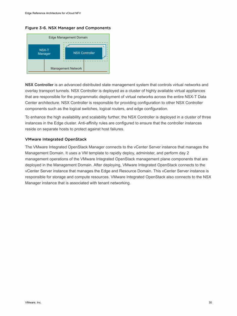
Figure 3-6. NSX Manager and Components
NSX-TManager
Edge Management Domain
NSX Controller
Management Network
NSX Controller is an advanced distributed state management system that controls virtual networks andoverlay transport tunnels. NSX Controller is deployed as a cluster of highly available virtual appliancesthat are responsible for the programmatic deployment of virtual networks across the entire NSX-T DataCenter architecture. NSX Controller is responsible for providing configuration to other NSX Controllercomponents such as the logical switches, logical routers, and edge configuration.
To enhance the high availability and scalability further, the NSX Controller is deployed in a cluster of threeinstances in the Edge cluster. Anti-affinity rules are configured to ensure that the controller instancesreside on separate hosts to protect against host failures.
VMware Integrated OpenStack
The VMware Integrated OpenStack Manager connects to the vCenter Server instance that manages theManagement Domain. It uses a VM template to rapidly deploy, administer, and perform day 2management operations of the VMware Integrated OpenStack management plane components that aredeployed in the Management Domain. After deploying, VMware Integrated OpenStack connects to thevCenter Server instance that manages the Edge and Resource Domain. This vCenter Server instance isresponsible for storage and compute resources. VMware Integrated OpenStack also connects to the NSXManager instance that is associated with tenant networking.
Edge Reference Architecture for vCloud NFV
VMware, Inc. 30
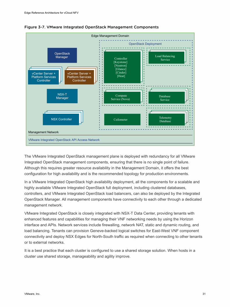
Figure 3-7. VMware Integrated OpenStack Management Components
Ceilometer
ComputeService (Nova)
DatabaseService
Controller[Keystone][Neutron][Glance][Cinder][Heat]
TelemetryDatabase
Load BalancingService
OpenStack Deployment
VMware Integrated OpenStack API Access Network
vCenter Server +Platform Services
Controller
NSX-TManager
Edge Management Domain
OpenStackManager
vCenter Server +Platform Services
Controller
Management Network
NSX Controller
The VMware Integrated OpenStack management plane is deployed with redundancy for all VMwareIntegrated OpenStack management components, ensuring that there is no single point of failure.Although this requires greater resource availability in the Management Domain, it offers the bestconfiguration for high availability and is the recommended topology for production environments.
In a VMware Integrated OpenStack high availability deployment, all the components for a scalable andhighly available VMware Integrated OpenStack full deployment, including clustered databases,controllers, and VMware Integrated OpenStack load balancers, can also be deployed by the IntegratedOpenStack Manager. All management components have connectivity to each other through a dedicatedmanagement network.
VMware Integrated OpenStack is closely integrated with NSX-T Data Center, providing tenants withenhanced features and capabilities for managing their VNF networking needs by using the Horizoninterface and APIs. Network services include firewalling, network NAT, static and dynamic routing, andload balancing. Tenants can provision Geneve-backed logical switches for East-West VNF componentconnectivity and deploy NSX Edges for North-South traffic as required when connecting to other tenantsor to external networks.
It is a best practice that each cluster is configured to use a shared storage solution. When hosts in acluster use shared storage, manageability and agility improve.
Edge Reference Architecture for vCloud NFV
VMware, Inc. 31

Telco Edge Management Domain NetworkingThe Telco Edge Management Domain networking consists of the infrastructure and Virtual Machinenetworks. The following diagram shows all the virtual switches and port groups of the ManagementDomain. The VLAN numbers here are for illustrative purposes only.
Edge Reference Architecture for vCloud NFV
VMware, Inc. 32
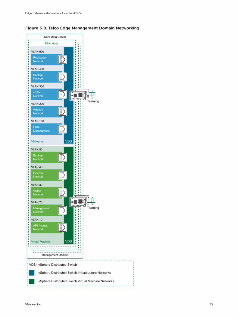
Figure 3-8. Telco Edge Management Domain Networking
API AccessNetwork
VLAN 10
VLAN 50
VLAN 30
VLAN 20
BackupNetwork
VCHANetwork
ManagementNetwork
VLAN 400
VLAN 500
VLAN 100
VLAN 200
VLAN 300
ESXiManagement
vMotionNetwork
BackupNetwork
vSANNetwork
ReplicationNetwork
VDS
VDS
VMKernel
Virtual Machine
Teaming
vSphere Distributed Switch Infrastructure Networks
VDS: vSphere Distributed Switch
vSphere Distributed Switch Virtual Machine Networks
Teaming
ESXi Host
Core Data Center
Management Domain
VLAN 40
ExternalNetwork
Edge Reference Architecture for vCloud NFV
VMware, Inc. 33
Telco Edge Compute DomainThis section describes the components of the Edge Compute Domain and their functions. NSX Edgenode and VNFs are placed in the Edge Compute Domain cluster that forms the virtual network services.
Telco Edge Compute Domain ComponentsThe Edge Compute Domain provides the runtime environment for the network functions. The sectioncovers the logical tenancy and networking components.
Projects
In VMware Integrated OpenStack, cloud administrators manage permissions through user, group, andproject definitions. Projects in OpenStack are equal to tenants in vCloud NFV. A project is theadministrative container where Telco workloads are deployed and managed.
Tenant VDCs
A Tenant VDC allows creation of virtual data centers for tenants under different compute nodes that offerspecific SLA levels for each Telco workload. While quotas on projects set limits on the OpenStackresources, Tenant VDCs allow providing resource guarantees for tenants and avoid noisy neighborscenarios in a multitenant environment.
VNFs
One or more VMs that are deployed in the tenancy to provide specific network functions or Telco services.
NSX Edge
NSX Edge provides network edge security and gateway services to isolate a virtualized network. TheNSX Edge logical (distributed) router provides East-West distributed routing with tenant IP address spaceand data path isolation. The NSX Edge gateway connects isolated, stub networks to shared (uplink)networks by providing common gateway services such as DHCP, VPN, NAT, dynamic routing, and LoadBalancing.
Telco Edge Compute Domain NetworkingThe networking of the Edge Compute Domain is highly dependent on the network topology that isrequired by the Telco workloads that are deployed by the tenant. This section describes the networkbuilding blocks as required by tenant workloads and is applicable to both VNF and other Telco workloads.
Following diagrams depict example scenarios and how networking components such as VDS, N-VDS,and SR-IOV can be used to provide network connectivity to the Telco workloads. The VLAN numbers inthe following figure are for illustrative purposes only.
Edge Reference Architecture for vCloud NFV
VMware, Inc. 34

Figure 3-9. Telco Edge Compute Domain Networking
ESXi Host
Edge Site Edge Site
VMKernel
VLAN 70
Virtual Machine
VLAN 100
VLAN 200
VLAN 300
vSAN Network
VLAN 60
VLAN 20
ESXi Management
vMotion Network
Management Network
Overlay Network
Enhanced Data Path Network
VDS
N-VDS(S)/ (E)
Teaming
VMKernel
Trunk VLAN 0-4094
Trunk VLAN 0-4094
Overlay Network
External Network
VDS
Teaming
TeamingN-VDS(E)
Teaming
Data and Control Plane using NSX-T
ESXi Host
Compute Domain Compute Domain
VMKernel
VLAN 70
Virtual Machine
VLAN 100
VLAN 200
VLAN 300
vSAN Network
VLAN 20
ESXi Management
vMotion Network
Management Network
Overlay Network
VDS
N-VDS(S)
Teaming
VMKernel
Trunk VLAN 0-4094
Trunk VLAN 0-4094
Overlay Network
External Network
VDS
Teaming
Teaming
Control Plane using NSX-T
Edge Reference Architecture for vCloud NFV
VMware, Inc. 35
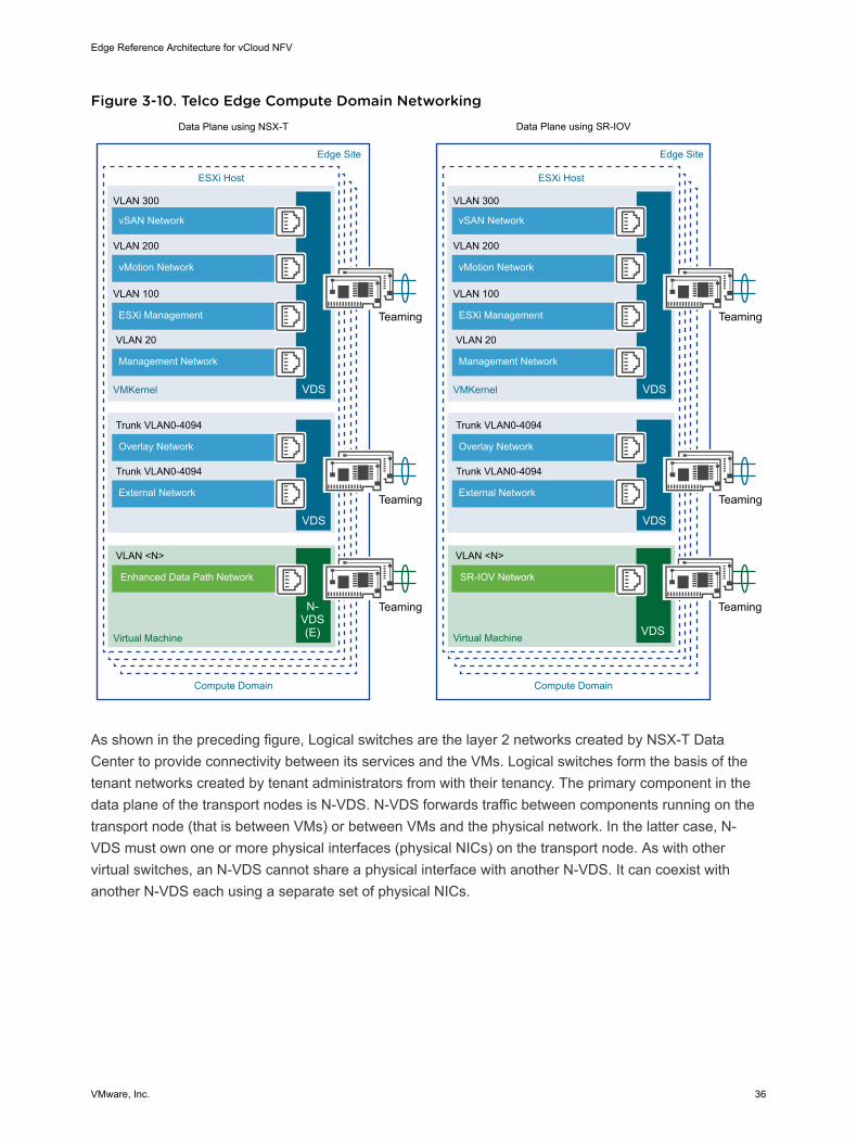
Figure 3-10. Telco Edge Compute Domain Networking
ESXi Host
Edge Site Edge Site
VMKernel
Virtual Machine
VLAN 100
VLAN 200
VLAN 300
vSAN Network
VLAN <N>
VLAN 20
ESXi Management
vMotion Network
Management Network
Enhanced Data Path Network
VDS
Teaming
TeamingN-VDS(E)
ESXi Host
Compute Domain Compute Domain
VMKernel
Virtual Machine
VLAN 100
VLAN 200
VLAN 300
vSAN Network
VLAN 20
ESXi Management
vMotion Network
Management Network
VDS
Teaming
Trunk VLAN0-4094
Trunk VLAN0-4094
Overlay Network
External Network
VDS
Teaming
Trunk VLAN0-4094
Trunk VLAN0-4094
Overlay Network
External Network
VDS
Teaming
Data Plane using NSX-T Data Plane using SR-IOV
VLAN <N>
SR-IOV Network
Teaming
VDS
As shown in the preceding figure, Logical switches are the layer 2 networks created by NSX-T DataCenter to provide connectivity between its services and the VMs. Logical switches form the basis of thetenant networks created by tenant administrators from with their tenancy. The primary component in thedata plane of the transport nodes is N-VDS. N-VDS forwards traffic between components running on thetransport node (that is between VMs) or between VMs and the physical network. In the latter case, N-VDS must own one or more physical interfaces (physical NICs) on the transport node. As with othervirtual switches, an N-VDS cannot share a physical interface with another N-VDS. It can coexist withanother N-VDS each using a separate set of physical NICs.
Edge Reference Architecture for vCloud NFV
VMware, Inc. 36
Telco Edge Site Networking
Edge sites can be connected to two separate domains. The first domain is an Internet breakout where thetunneled traffic from the user equipment is terminated and routed as IP packets to the Internet. Thesecond is where traffic remains tunneled to the central site (as happens today with user traffic). In bothcases, the Edge site uses a physical router as the egress device to transport traffic to the Internet or tothe central site.
There are multiple options for the physical router egress connectivity, such as metro Ethernet and MPLS.The technology that is used to connect Edge to Internet or Core sitedoes not impact this referencearchitecture, except for certain latency and speed requirements.
Logical Routing
The NSX-T Data Center platform provides the ability to interconnect both virtual and physical workloadsthat are deployed in different logical layer 2 networks. NSX-T enables the creation of network elementslike switches and routers as software logical constructs and embeds them in the hypervisor layer,abstracted from the underlying physical hardware.
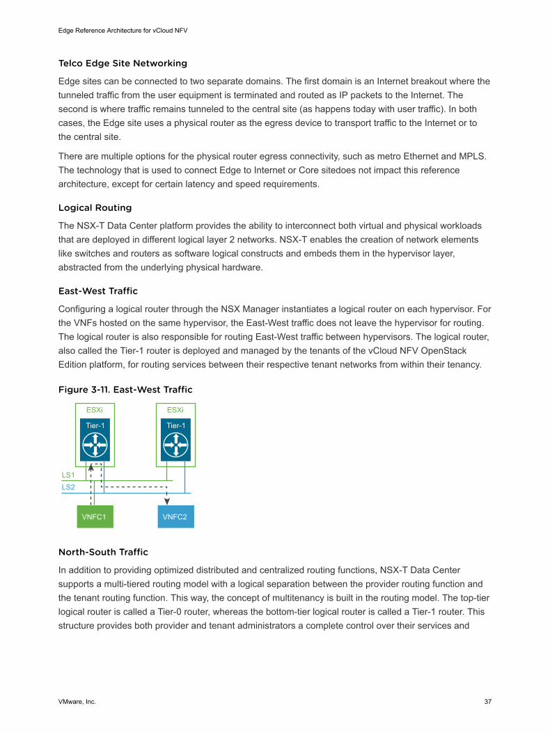
East-West Traffic
Configuring a logical router through the NSX Manager instantiates a logical router on each hypervisor. Forthe VNFs hosted on the same hypervisor, the East-West traffic does not leave the hypervisor for routing.The logical router is also responsible for routing East-West traffic between hypervisors. The logical router,also called the Tier-1 router is deployed and managed by the tenants of the vCloud NFV OpenStackEdition platform, for routing services between their respective tenant networks from within their tenancy.
Figure 3-11. East-West Traffic
Tier-1
ESXi
Tier-1
ESXi
LS1LS2
VNFC1 VNFC2
North-South Traffic
In addition to providing optimized distributed and centralized routing functions, NSX-T Data Centersupports a multi-tiered routing model with a logical separation between the provider routing function andthe tenant routing function. This way, the concept of multitenancy is built in the routing model. The top-tierlogical router is called a Tier-0 router, whereas the bottom-tier logical router is called a Tier-1 router. Thisstructure provides both provider and tenant administrators a complete control over their services and
Edge Reference Architecture for vCloud NFV
VMware, Inc. 37
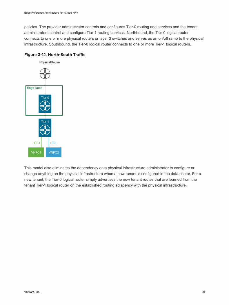
policies. The provider administrator controls and configures Tier-0 routing and services and the tenantadministrators control and configure Tier-1 routing services. Northbound, the Tier-0 logical routerconnects to one or more physical routers or layer 3 switches and serves as an on/off ramp to the physicalinfrastructure. Southbound, the Tier-0 logical router connects to one or more Tier-1 logical routers.
Figure 3-12. North-South Traffic
Tier-1
Tier-0
VNFC1 VNFC2
LIF1 LIF2
PhysicalRouter
Edge Node
This model also eliminates the dependency on a physical infrastructure administrator to configure orchange anything on the physical infrastructure when a new tenant is configured in the data center. For anew tenant, the Tier-0 logical router simply advertises the new tenant routes that are learned from thetenant Tier-1 logical router on the established routing adjacency with the physical infrastructure.
Edge Reference Architecture for vCloud NFV
VMware, Inc. 38
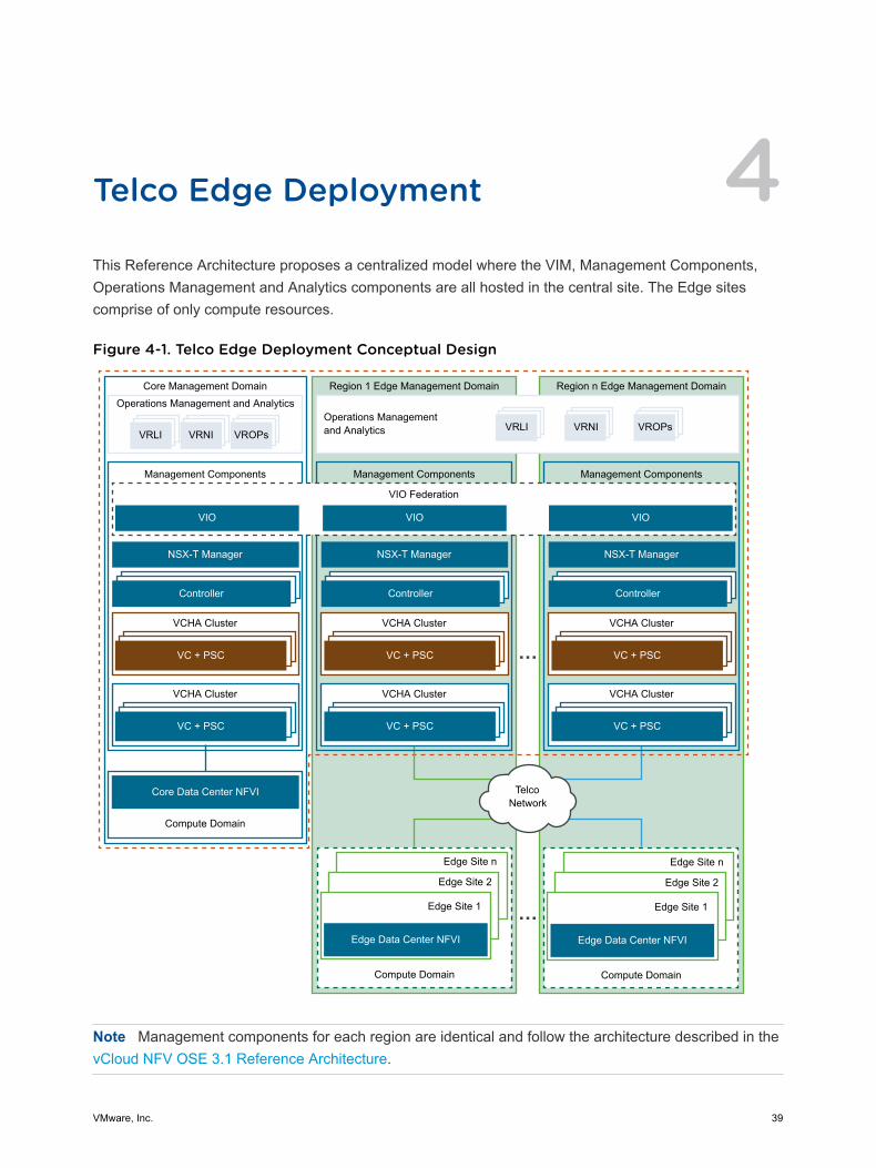
Telco Edge Deployment 4This Reference Architecture proposes a centralized model where the VIM, Management Components,Operations Management and Analytics components are all hosted in the central site. The Edge sitescomprise of only compute resources.
Figure 4-1. Telco Edge Deployment Conceptual Design
Operations Management and AnalyticsCore Management Domain
Management Components
VRLI VROPsVRNI
NSX-T Manager
Controller
VC + PSC
VCHA Cluster
Operations Management and Analytics
Region 1 Edge Management Domain
Management Components
VIO
VIO Federation
Region n Edge Management Domain
Management Components
VIO
VC + PSC
VCHA Cluster
Telco Network
Compute Domain
Core Data Center NFVI
NSX-T Manager
Controller
VC + PSC
VCHA Cluster
VC + PSC
VCHA Cluster
NSX-T Manager
Controller
VC + PSC
VCHA Cluster
VC + PSC
VCHA Cluster
Compute Domain
Edge Site 1
Edge Site 2
Edge Site n
Edge Data Center NFVI
Compute Domain
Edge Site 1
Edge Site 2
Edge Site n
Edge Data Center NFVI
VRLI VROPsVRNI
VIO
Note Management components for each region are identical and follow the architecture described in thevCloud NFV OSE 3.1 Reference Architecture.
VMware, Inc. 39
This chapter includes the following topics:
n Telco Edge Deployment Network Design
n Design Considerations
Telco Edge Deployment Network DesignThe vCloud NFV Edge Reference Architecture network solution consists of separate orchestration,management, control, and data planes.
Management Plane This plane is responsible for central configuration and monitoring. Themanagement plane helps in the automatic onboarding of CE/PE routersinto the NSX-T Edge T0/T1 overlay.
Control Plane This plane builds and maintains the network topology and makes decisionson traffic flows.
Data plane This plane is responsible for forwarding packets based on decisions fromthe control plane.
Note The WAN connectivity between Central and Edge sites is beyond the scope of this referencearchitecture; customers need to ensure L2/L3 connectivity between the two sites. All Edge Sites areconnected to its respective aggregation site which is the corresponding Core data center for the region.
Edge Reference Architecture for vCloud NFV
VMware, Inc. 40

Figure 4-2. Telco Edge Deployment Network Design
Core Data Center
Operations Management and Analytics
Core Management Domain
Region 1
Region n
Region 1 Edge Management Domain
Region n Edge Management Domain
Management Components
Tenant Networks
Tenant Networks
Management Network
Management Network
Management Network
Management Network
Operations Management and Analytics
Management Components
VRF
VRF
Compute Domain
Edge Site 1
Edge Site 2
Edge Site n
Edge Data Center NFVI
Telco Router
Telco RouterTier-1 Tier-0
Compute Domain
Core Data Center NFVI
Tier-1 Tier-0
Telco Network
eBGP
eBGP
Design ConsiderationsThis reference architecture assumes a separate network connection over Layer 3 for managementconnectivity between the VIM components and its edge sites for traffic such as that between vCenterServer and Edge site ESXi hosts. NSX-T Manager also uses this network for management of NSX-TEdge Nodes at the Edge site.
Edge Reference Architecture for vCloud NFV
VMware, Inc. 41

A pair of NSX-T Edge Nodes (in VM form factor) is used at each Edge site for the logical to physicalnetwork function and also to assist in mapping of tenant routers when a multi-tenant environment isneeded. Note that segregation of tenants and QoS at the networking level may increase the number ofEdge Nodes per site.
Note The end-to-end round trip latency between any Edge site and core site should not exceed 150 ms.Recommended bandwidth between Edge and core sites is 10 Gbps.
For segmentation of the individual traffic types, such as specific tenant traffic or management traffic, it isbest to connect each Edge network (traffic) segment to a specific VRF (Virtual Routing & Forwardinginstance) at each PE router. A similar theme of per VRF traffic forwarding is followed at the core site forthe core to Edge traffic.
VLAN-based network segmentation is restricted to within a data center. There is no VLAN stretchingbetween core and Edge sites.
Network RedundancyThe vCloud NFV Edge reference architecture configuration has two Edge nodes (in VM form factor) inactive/standby mode to connect to the Provider Edge (PE) router at the Edge site. To define the highavailability configuration, the administrator from the Core data center vCenter Server must use the controlplane network VRF to configure HA appliance name with the mode as primary on that vCenter cluster.
Operations ManagementThere are two models for placement of the operations management components such as vROps, vRNI,and vRLI. The central components of these products are always placed at the core site. Scaling of theseproducts depends on the number of Edge sites under management and the total number of workloads atthose Edge sites. The remote collector components of these components are to be placed at the Edgesites. There are three FCAPs collectors, Remote Collector for vROPs, Proxy for vRNI, and Syslogcollector for vRLI. For potentially large-scale deployments, consider placing the remote collectors at theEdge sites.
Network TenancyThe vCloud NFV Edge Reference Architecture relies on NSX-T to provide network tenancy for end-to-endisolation capabilities by deploying multiple tiers of distributed routing through Tier-0 and Tier-1 routers inthe networking stack.
Edge Reference Architecture for vCloud NFV
VMware, Inc. 42
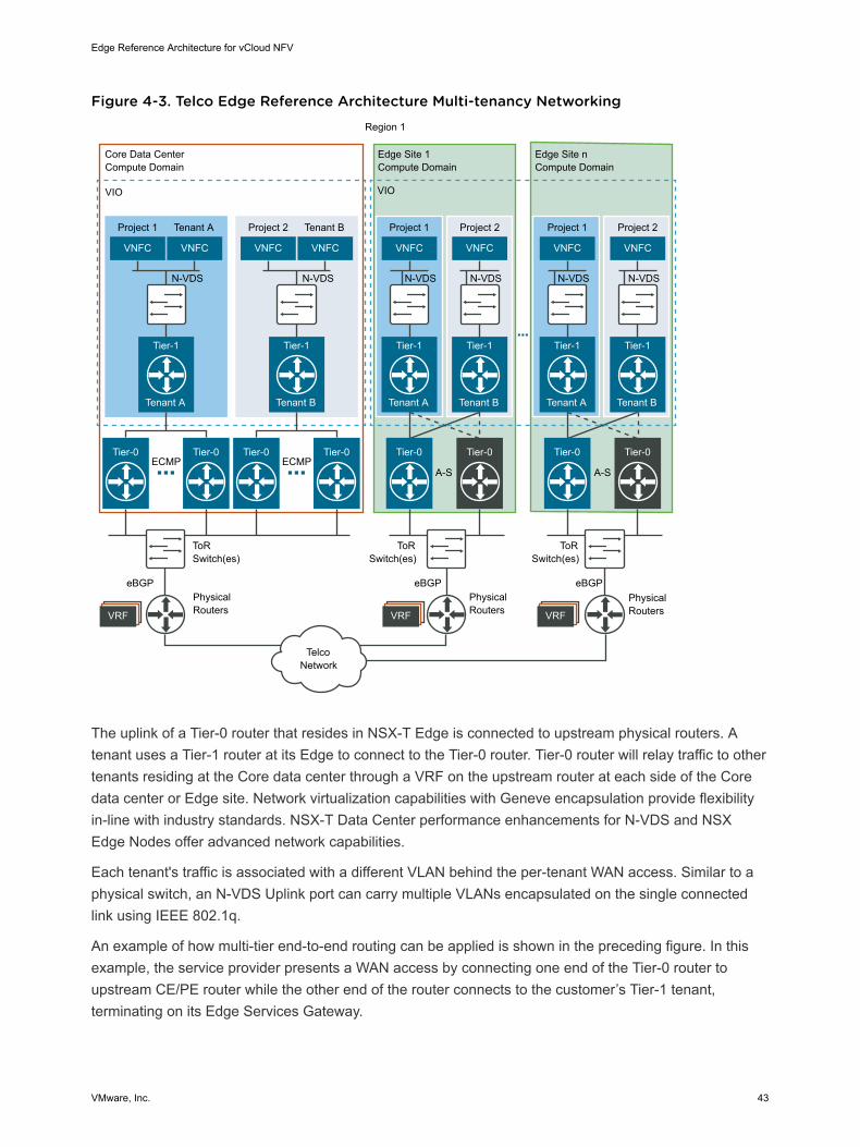
Figure 4-3. Telco Edge Reference Architecture Multi-tenancy Networking
VNFC
VRFVRFVRF
Tier-1
Tenant A
Tier-0 Tier-0
N-VDS
ECMP
ToR Switch(es)
Physical Routers
Physical Routers
Physical Routers
eBGP eBGP eBGP
ToR Switch(es)
ToR Switch(es)
Project 1
VNFC
Tenant A
VNFC
Tier-1
Tenant B
Tier-0 Tier-0
N-VDS
ECMPA-S A-S
Project 2
Core Data Center Compute Domain
VIO VIO
Edge Site 1 Compute Domain
Edge Site n Compute Domain
Region 1
VNFC
Tenant B
VNFC
Tier-1
Tenant A
Tier-0
N-VDS
Project 1
VNFC
Tier-1
Tenant B
Tier-0
N-VDS
Project 2
VNFC
Tier-1
Tenant A
Tier-0
N-VDS
Project 1
VNFC
Tier-1
Tenant B
Tier-0
N-VDS
Project 2
Telco Network
The uplink of a Tier-0 router that resides in NSX-T Edge is connected to upstream physical routers. Atenant uses a Tier-1 router at its Edge to connect to the Tier-0 router. Tier-0 router will relay traffic to othertenants residing at the Core data center through a VRF on the upstream router at each side of the Coredata center or Edge site. Network virtualization capabilities with Geneve encapsulation provide flexibilityin-line with industry standards. NSX-T Data Center performance enhancements for N-VDS and NSXEdge Nodes offer advanced network capabilities.
Each tenant's traffic is associated with a different VLAN behind the per-tenant WAN access. Similar to aphysical switch, an N-VDS Uplink port can carry multiple VLANs encapsulated on the single connectedlink using IEEE 802.1q.
An example of how multi-tier end-to-end routing can be applied is shown in the preceding figure. In thisexample, the service provider presents a WAN access by connecting one end of the Tier-0 router toupstream CE/PE router while the other end of the router connects to the customer’s Tier-1 tenant,terminating on its Edge Services Gateway.
Edge Reference Architecture for vCloud NFV
VMware, Inc. 43
Telco Edge AnalyticalArchitecture 5CSPs can enable the vCloud NFV Edge Reference Architecture platform for day 1 and day 2 operationsafter the platform is deployed in the cloud provider topology. The platform is integrated with an operationsmanagement suite that provides capabilities for health monitoring, issue isolation, security, andremediation of the NFVI and VNFs.
The NFVI operations management framework defines and packages a five-step approach to make day 1and day 2 workflows operational.
1 Onboard service operations.
2 Service launch and monitoring.
3 Dynamic optimizations.
4 Issue isolation.
5 Demand planning and expansion.
The integrated operational intelligence adapts to the dynamic characteristics of the NFV infrastructure toensure service quality and issue resolution. Some of the key characteristics include:
Dynamic resourcediscovery
Distributed and complex topologies together with workloads in motionrequire dynamic resource and service discovery. The platform providescontinuous visibility over service provisioning, workload migrations, auto-scaling, elastic networking, and network-sliced multitenancy that spansacross VNFs, hosts, clusters, and sites.
SLA management Continuous operational intelligence and alert notifications enable proactiveservice optimizations, capacity scale-out or scale-in, SLA violations,configuration and compliance gaps, and security vulnerabilities.
Remediation Reduced MTTU and timely issue isolation for improved service reliabilityand availability. Prioritized alerting, recommendations, and advanced logsearching enable isolation of service issues across physical and overlaynetworks.
VMware, Inc. 44

Security and policycontrols
Multivendor services operating in a shared resource pool can createsecurity risks within the virtual environment.
n Ability to profile and monitor traffic segments, types, and destination torecommend security rules and policies for north-south and east-westtraffic.
n Identification of security policy and configuration violations,performance impacts, and traffic routes.
Capacity planning andforecasting
New business models and flexible networks demand efficient capacityplanning and forecasting abilities in contrast to the traditional approach ofover-provisioning that is costly and unrealistic.
The framework continuously collects data from local and distributed agents, correlating, analyzing andenabling day 2 operations. The analytical intelligence can be also queried and triggered by third-partycomponents such as existing assurance engines, NMS, EMS, OSS/BSS, and VNFM and NFVO forclosed loop remediation.
Figure 5-1. Analytical Reference Architecture
...
Topology Performance Optimization
Capacity Causality Compliance
Remediate Configuration Efficiency
Performance Security
Compliance Planning
Search Configuration API
Dashboard
NotificationvRealize Log Insight
Log Analysis Machine Learning RCA Clustering Search
Discovery Correlation Analytics Reporting Alerting
IPFIXRouterSwitch
PNF
vCenterServer
NSX
VMwareIntegratedOpenStack
SNMPSyslog
vRealize Operations vRealize Network Insight
vSAN Collectors
CSPs can deploy the operations management components in the Telco Edge Management Domain andcentralize them across the cloud topology, assuming that inter-site latency constraints are met.
n vRealize Operations Manager collects compute, storage, and networking data providing performanceand fault visibility over hosts, hypervisors, virtual machines, clusters, and site.
n vRealize Log Insight captures unstructured data from the environment, providing log analysis andanalytics for issue isolation. Platform component logs and events are ingested and tokenized, andmined for intelligence so that they can be searched, filtered, aggregated, and alerted.
Edge Reference Architecture for vCloud NFV
VMware, Inc. 45
n vRealize Network Insight provides layer 2, 3, and 4 visibility into the virtual and physical networks andsecurity policy gaps. The engine is integrated with the NFVI networking fabric, ingesting data thatranges in performance metrics, device and network configuration, IPFIX flow, and SNMP. It discoversgaps in the network traffic optimization, micro-segmentation, compliance, security violations, trafficrouting, and performance.
This chapter includes the following topics:
n Introduction to Analytics for Telco Edge
n Analytic Components for Edge
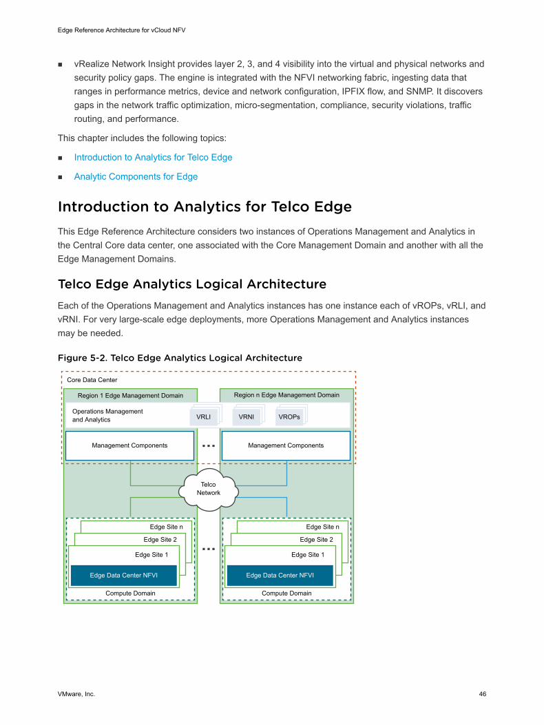
Introduction to Analytics for Telco EdgeThis Edge Reference Architecture considers two instances of Operations Management and Analytics inthe Central Core data center, one associated with the Core Management Domain and another with all theEdge Management Domains.
Telco Edge Analytics Logical ArchitectureEach of the Operations Management and Analytics instances has one instance each of vROPs, vRLI, andvRNI. For very large-scale edge deployments, more Operations Management and Analytics instancesmay be needed.
Figure 5-2. Telco Edge Analytics Logical Architecture
Compute Domain
Edge Site 1
Edge Site 2
Edge Site n
Edge Data Center NFVI
Core Data Center
Operations Management and Analytics
Management Components Management Components
Region 1 Edge Management Domain Region n Edge Management Domain
VRLI VROPsVRNI
Telco Network
Compute Domain
Edge Site 1
Edge Site 2
Edge Site n
Edge Data Center NFVI
Edge Reference Architecture for vCloud NFV
VMware, Inc. 46
With the Operations Management and Analytics components being placed in the central Core datacenter, it is important to limit the distance between the central site and the edge site to ensure that thelatency is below 150 ms RTT. For large-scale deployments, remote collector components of vRNI, vRLI,or vROps may be needed to address collection end-point scalability and to facilitate bulk data export.
Analytic Components for EdgeThe operations management components are deployed as a centralized function that is capable of day 1and day 2 operations spanning the CSP's deployment topology. The data collection architecture isspecific to each operations management component with a centralized single pane for monitoring,reporting, troubleshooting, and closed-loop automation.
vRealize Operations ManagervRealize Operations Manager is configured with adapters for vCenter Server, End-Point OperationsManagement, vSAN, OpenStack and NSX. These adapters are necessary to start collecting data from theinfrastructure.
For large scale deployments of vRealize Operations Manager, a remote collector is an optionalcomponent that allows vRealize Operations Manager to perform monitoring at scale. The remote collectoris typically deployed in the Edge site(s) to reduce the frequency of updates from Core data center to theEdge sites, and/or reduce the load on the vRealize Operations Manager analytics cluster.
By default, VMware offers Extra Small, Small, Medium, Large, and Extra Large configurations duringinstallation. The CSP can size the environment according to the existing infrastructure to be monitored.After the vRealize Operations Manager instance outgrows the existing size, the CSP must expand thecluster to add nodes of the same size. See the vRealize Operations Manager Sizing Guidelines.
vRealize Log InsightVMware vRealize Log Insight delivers real-time, heterogeneous and highly scalable log management withintuitive, actionable dashboards, sophisticated analytics and broad third-party extensibility, providing deepoperational visibility and faster troubleshooting. The key components include built-in Syslog server andLog Insight agent which gathers log events natively from multiple syslog data sources through specialmanagement packs and intelligently group.
vRealize Log Insight provides preset VM sizes that the CSP can select from to meet the ingestionrequirements of their environment, Extra Small, Small, Medium, Large, and Extra Large configurations.These presets are certified size combinations of compute and disk resources, though extra resources canbe added later. For sizing details, see the VMware Documentation
vRealize Network InsightvRealize Network Insight provides operations for software-defined networking and security across virtualand physical infrastructure with micro-segmentation planning that can be scaled to thousands of VNFs.
Edge Reference Architecture for vCloud NFV
VMware, Inc. 47
The vRealize Network Insight architecture consists of a platform VM, a proxy VM, and data sources. Theplatform VM provides analytics, storage, and a user interface to the data. The proxy VM, or the collector,collects data using various protocols such as HTTPS, SSH, CLI, and SNMP, depending on the sourceand the configuration. A variety of data sources are supported, including vCenter Server, NSX-T DataCenter, firewalls, and various switch vendors.
The platform VM is deployed as a single cluster to provide high availability and scale. A minimum of threeplatform VMs are required in the cluster. The proxy VMs are used to collect data and can be deployed ina single data center or distributed across sites. Depending on the amount of data that will be collected,typically CSPs need one or more proxy VMs.
Ensure that the system meets the minimum hardware configurations to install vRealize Network Insight.For sizing details, see VMware Documentation.
Edge Reference Architecture for vCloud NFV
VMware, Inc. 48
Architectural Realization 6This section covers a set of solutions and use case scenarios to modernize the CSP cloud infrastructureenvironment with vCloud NFV OpenStack Edition.
This chapter includes the following topics:
n Multi Tenancy
n Telco Edge Workload Placement
n Availability and Disaster Recovery
Multi TenancyMultitenancy defines the isolation of resources and networks to deliver applications with quality. Becausemultiple tenants share the same resource infrastructure, secure multitenancy can be enabled by usingVMware Integrated OpenStack in a single cloud island and across distributed clouds. In addition to thebuilt-in workload and resource optimization capabilities, predictive optimization can be enabled withanalytics by using features like vSphere DRS.
CSPs can converge their resource infrastructures across their IT and Network clouds, enabling a multi-tenant IaaS realization. Consumption models can serve both internal and external tenants over thecommon shared infrastructure to deploy and operate their respective workloads and services.
A unit of tenancy within the scope of a VIO deployment is a Project. It is defined as a composition ofdedicated compute, storage, and network resources and as workloads. The tenant is associated with aset of operational policies and SLAs. The Project can be bound to a single site or shared across manysites.
Using the Tenant Virtual Data Center available with the VMware Integrated OpenStack Carrier Edition, aCSP can create virtual datacenters for tenants under different compute nodes that offer specific servicelevel agreements for each telecommunication workload. By using the Tenant Virtual Data Center toallocate CPU and memory for an OpenStack project or tenant on a compute node, CSPs provide aresource guarantee for tenants and avoid noisy neighbor scenarios in a multi-tenant environment.
The design objectives include considerations for the end-to-end compute and network resource isolationfrom the Core data center to the Edge data centers.
VMware, Inc. 49
Management PlaneThe management plane functions reside in the Edge Management Domain at the Core data center. Theyare responsible for the orchestration of resources and operations. The management plane functions arelocal to each cloud instance providing the infrastructure management, network management, andoperations management capabilities.
Resource isolation for compute and networking design are enabled together with vCenter Server, NSXManager, and VMware Integrated OpenStack. Irrespective of the Domain deployment configuration,VMware Integrated OpenStack provides the abstraction layers for multi-tenancy. vCenter Server providesthe infrastructure for fine-grained allocation and partitioning of compute and storage resources, whereasNSX-T Data Center creates the network virtualization layer.
The concept of tenancy also introduces multiple administrative ownerships. A cloud provider, that is theCSP admin, can create a resource pool allocation for a tenant who in turn can manage the underlyinginfrastructure and overlay networking. In VMware Integrated OpenStack, multiple tenants can be definedwith assigned RBAC privileges to manage compute and network resources and also the VNF onboarding.
Compute IsolationAllocation of compute and storage resources ensures that there is an optimal footprint available to eachtenant that is used to deploy workloads, with room for expansion to meet future demand.
Tenant vDCs provide a secure multitenant environment to deploy VNFs. Compute resources are definedas resource pools when a Tenant vDC is created. The resource pool is an allocation of memory and CPUfrom the available shared infrastructure, assignable to a Tenant vDC. More resources can be added to apool as required. The Tenant vDC can also stretch across multiple hosts in a resource cluster residing indifferent physical racks. The same constructs for resource management are used to implementmultitenancy in the Edge data centers.
Though the resource pools can be further sub-segmented into smaller resource pools, this is not arecommended design.
Network IsolationThe advanced networking model of NSX-T Data Center provides a fully-isolated and secure traffic pathsacross workloads and tenant switch or routing fabric. Advanced security policies and rules can be appliedat the VM boundary to further control unwarranted traffic.
NSX-T Data Center introduces a two-tiered routing architecture which enables the management ofnetworks at the provider (Tier-0) and tenant (Tier-1) tiers. The provider routing tier is attached to thephysical network for North-South traffic, while the tenant routing context can connect to the providerTier-0 and manage East-West communications. The Tier-0 provides traffic termination to the cloudphysical gateways and existing CSP underlay networks for inter-cloud traffic communication andcommunication to remote Edge data centers.
Each Tenant vDC has a single Tier-1 distributed router that provides the intra-tenant routing capabilities. Itcan also be enabled for stateful services such as firewall, NAT, load balancer, and so on. VMs belongingto Tenant A can be plumbed to multiple logical interfaces for layer 2 and layer 3 connectivity.
Edge Reference Architecture for vCloud NFV
VMware, Inc. 50
By using VMware Integrated OpenStack as the IaaS layer, user profile and RBAC policies can be used toenable and restrict access to the networking fabric at the Tier-1 level.
QoS Resource AllocationTo avoid contention and starvation, QoS policies along with compute, storage, and network isolationpolicies must be applied consistently to the workloads.
The CSP admin can allocate and reserve compute resources for tenants by using Tenant vDCs. EveryTenant vDC is associated with a vSphere resource pool the resource settings of which are managed fromVMware Integrated OpenStack. This ensures that every Tenant vDC consumes resources to which it isentitled, without exceeding the infrastructure resource limits, such as CPU clock cycles and total memory.
QoS policies can be applied to VMs so that they receive a fair share of resources across theinfrastructure pool. Each VM configuration is taken from a template that is called a Flavor. QoS can beconfigured by using Flavor metadata to allocate CPU (MHz), memory (MB), storage (IOPS), and virtualinterfaces (Mbps).
QoS can be shaped by setting boundary parameters that control the elasticity and priority of theresources that are assigned to the VNF component executing within the VM.
Reservation is the minimum guarantee. Reservations ensure a minimum guarantee to each VM when itis launched.
Limit is the upper boundary. Should be used with caution in a production environment, because itrestricts the VM from bursting utilization beyond the configured boundaries.
Shares are the distribution of resources under contention. Shares can be used to prioritize certainworkloads over others in case of contention. If the resources are over-provisioned across VMs and thereis a resource contention, the VM with the higher shares gets the proportional resource assignment.
For control plane workload functions, a higher order elasticity can be acceptable and memory can bereserved based on the workload requirement. For data plane intensive workloads, both CPU and memorymust be fully reserved. Storage IO and network throughput reservations need to be determined based onthe VNF needs.
Telco Edge Workload PlacementThe placement of workloads is typically a subset of the VNF onboarding process and is a collaborativeeffort between the VNF vendor and the CSP. A prescriptive set of steps must be followed to package anddeploy a VNF. The VMware Ready for NFV program is a good vehicle to pre-certify the VNFs and theonboarding compliance with the vCloud NFV OpenStack Edition platform to ensure smooth deployment inthe CSP environment.
Before a VNF is onboarded, the VNF vendor must provide the CSP with all the prerequisites for thesuccessful onboarding of the VNF. This includes information such as the VNF format, number of therequired networks, East-West and North-South network connectivity, routing policy, security policy, IPranges, and performance requirements.
Edge Reference Architecture for vCloud NFV
VMware, Inc. 51
VNF Onboarding with VMware Integrated OpenStackAfter the initial VNF requirements, images, and formats are clarified, a project must be created to deploythe VNF in an operational environment. Projects are the VMware Integrated OpenStack constructs thatmap to tenants. Administrators create projects and assign users to each project. Permissions aremanaged through definitions for user, group, and project. Users have a further restricted set of rights andprivileges. Users are limited to the projects to which they are assigned, although they can be assigned tomore than one project. When a user logs in to a project, they are authenticated by Keystone. Once theuser is authenticated, they can perform operations within the project.
Edge Reference Architecture for vCloud NFV
VMware, Inc. 52
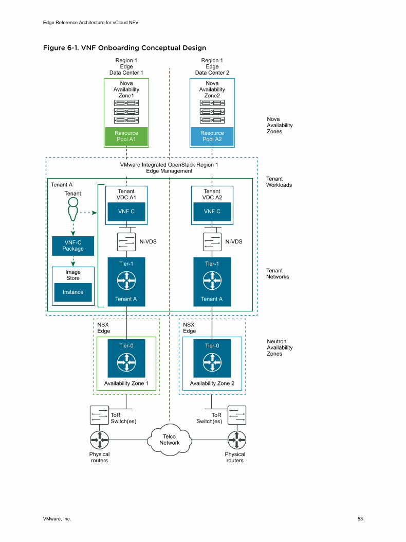
Figure 6-1. VNF Onboarding Conceptual Design
ToR Switch(es)
ToR Switch(es)
Physical routers
Physical routers
Tenant ATenant
VNF-C Package
Instance
Image Store
Nova Availability Zones
Neutron Availability Zones
Tenant Workloads
Tenant Networks
VMware Integrated OpenStack Region 1 Edge Management
Resource Pool A2
Availability Zone 2
NSX Edge
VNF C
Tier-1
Tenant A
Tier-0Tier-0
Nova Availability
Zone2
Region 1 Edge
Data Center 2
N-VDS
Tenant VDC A2
Resource Pool A1
Availability Zone 1
NSX Edge
VNF C
Tier-1
Tenant A
Nova Availability
Zone1
Region 1 Edge
Data Center 1
N-VDS
Tenant VDC A1
Telco Network
Edge Reference Architecture for vCloud NFV
VMware, Inc. 53
Resource AllocationWhen building a project for the VNF, the administrator must set the initial quota limits for the project. Forfine-grained resource allocation and control, the quota of the resources that are available to a project canbe further divided using Tenant vDCs. A Tenant vDC provides resource isolation and guaranteed resourceavailability for each tenant. Quotas are the operational limits that configure the amount of systemresources that are available per project. Quotas can be enforced at a project and user level. When a userlogs in to a project, they see an overview of the project including the resources that are provided for them,the resources they have consumed, and the remaining resources.
Resource allocation at the Edge data centers leverage the same mechanism as in the core data center.Tenant VDCs are created at the Edge data center to carve resources for the tenant Edge workloads andassigned to the respective project for the tenant, ensuring consistent level of fine-grained resourceallocation and control across the infrastructure.
VNF NetworkingBased on specific VNF networking requirements, a tenant can provision East-West connectivity, securitygroups, firewalls, micro-segmentation, NAT, and LBaaS using the VMware Integrated OpenStack userinterface or command line. VNF North-South connectivity is established by connecting tenant networks toexternal networks through NSX-T Data Center Tier-0 routers that are deployed in Edge nodes. Externalnetworks are created by administrators and a variety of VNF routing scenarios are possible.
After the VNFs are deployed, their routing, switching, and security policies must be configured. There aremany different infrastructure services available that can be configured in different ways. This documentdiscusses few of these options in the later sections.
Tenant networks are accessible by all Tenant vDCs within the project in the same data center. Therefore,the implementation of East-West connectivity between VNF-Cs in the same Tenant vDC in the Core datacenter and the connectivity between VNF-Cs in Tenant vDCs in the Edge data center belonging to thesame project is identical. Tenant networks are implemented as logical switches within the project. TheNorth-South network is a tenant network that is connected to the telecommunications network through anN-VDS Enhanced for data-intensive workloads or by using NVDS standard through an NSX Edge Cluster.VNFs utilize the North-South network of their data center when connectivity to remote data centers isrequired, such as when workloads in the Core data center need to communicate with those in the Edgedata center and vice-versa.
VMware Integrated OpenStack exposes a rich set of API calls to provide automation. The deployment ofVNFs can be automated by using a Heat template. With API calls, the upstream VNF-M and NFVO canautomate all aspects of the VNF life cycle.
VNF OnboardingThe VNF workload onboarding introduced in OSE 3.1 is still valid in this Edge reference architecture, withthe exception that compute nodes are now remotely located at an edge site. All the functional VNFworkload onboarding principles for VIO remain the same.
Edge Reference Architecture for vCloud NFV
VMware, Inc. 54
Edge sites contain VNFs that are run on VIO tenant networks that can potentially connect to other tenantnetworks at the Core data center where other VNF components may be deployed. The VIO instancesthemselves are deployed only at the Core data center and are inline with vCenter Server and itsassociated FCAPS (vROPs, VRNI, and vRLI). From a virtual infrastructure management perspective,vCenter Server in the Core data center is the only component talking to the compute nodes in the Edgedata center for workload placement and state management. The VIO instances in the Core data centerrelay virtual infrastructure requests to their respective vCenter Server and NSX-T Data Center VIMcomponents through the use of nova and neutron plugins respectively. These VIM components then carryout the tasks on behalf of VIO, such as provisioning tenant networks and workload resourcemanagement.
VNF PlacementAfter the VNF is onboarded, the tenant administrator deploys the VNF to either the Core data center orthe Edge data center depending on the defined policies and workload requirements.
The DRS, NUMA, and Nova Schedulers ensure that the initial placement of the workload meets the targethost aggregate and acceleration configurations defined in the policy. Dynamic workload balancingensures the polices are respected when there is resource contention. The workload balancing can bemanual, semi-supervised, or fully automated.
After the host aggregates are defined and configured, policies for workload placement should be definedfor the workload instances. The following diagram describes the workload placement architecture for theedge sites with VIO.
Edge Reference Architecture for vCloud NFV
VMware, Inc. 55

Figure 6-2. Telco Edge Multi-Tenancy with VMware Integrated OpenStack
Resource Pool A1
Resource Pool B1
VNF C
Tier-1
Tenant A
Tier-0 Tier-0
Nova Availability Zone1
Region 1 Edge Data Center 1
Tenant A
N-VDS
A-S
AZ1
ToR Switch(es)
Edge Cluster
Physical routers
Physical routers
Tenant VDC A1
VNF C
Tier-1
Tenant B
Tenant B
N-VDS
Tenant VDC B1
Resource Pool A2
Resource Pool B2
VNF C
Tier-1
Tenant A
Tier-0 Tier-0
Nova Availability Zone2Nova Availability Zones
Neutron Availability Zones
Tenant Workloads
Tenant Networks
Region 1 Edge Data Center 2
VMware Integrated OpenStack Region 1 Edge Management
Tenant A
N-VDS
A-S
AZ1
ToR Switch(es)
Edge Cluster
Tenant VDC A2
VNF C
Tier-1
Tenant B
Tenant B
N-VDS
Tenant VDC B2
Telco Network
Flavor Specification for InstancesFlavors are templates with a predefined or custom resource specification that are used to instantiateworkloads. A flavor can be configured with additional Extra Specs metadata parameters for workloadplacement.
Edge Reference Architecture for vCloud NFV
VMware, Inc. 56
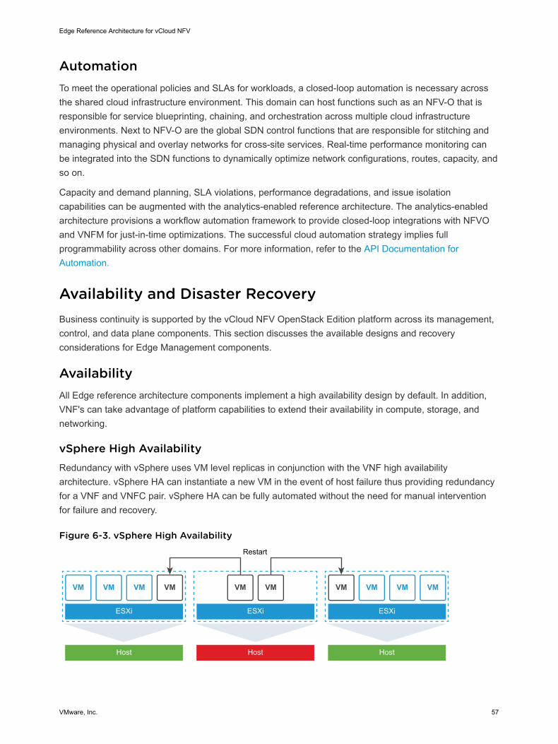
AutomationTo meet the operational policies and SLAs for workloads, a closed-loop automation is necessary acrossthe shared cloud infrastructure environment. This domain can host functions such as an NFV-O that isresponsible for service blueprinting, chaining, and orchestration across multiple cloud infrastructureenvironments. Next to NFV-O are the global SDN control functions that are responsible for stitching andmanaging physical and overlay networks for cross-site services. Real-time performance monitoring canbe integrated into the SDN functions to dynamically optimize network configurations, routes, capacity, andso on.
Capacity and demand planning, SLA violations, performance degradations, and issue isolationcapabilities can be augmented with the analytics-enabled reference architecture. The analytics-enabledarchitecture provisions a workflow automation framework to provide closed-loop integrations with NFVOand VNFM for just-in-time optimizations. The successful cloud automation strategy implies fullprogrammability across other domains. For more information, refer to the API Documentation forAutomation.
Availability and Disaster RecoveryBusiness continuity is supported by the vCloud NFV OpenStack Edition platform across its management,control, and data plane components. This section discusses the available designs and recoveryconsiderations for Edge Management components.
AvailabilityAll Edge reference architecture components implement a high availability design by default. In addition,VNF's can take advantage of platform capabilities to extend their availability in compute, storage, andnetworking.
vSphere High AvailabilityRedundancy with vSphere uses VM level replicas in conjunction with the VNF high availabilityarchitecture. vSphere HA can instantiate a new VM in the event of host failure thus providing redundancyfor a VNF and VNFC pair. vSphere HA can be fully automated without the need for manual interventionfor failure and recovery.
Figure 6-3. vSphere High Availability
ESXi
Host Host Host
ESXi
Restart
ESXi
Edge Reference Architecture for vCloud NFV
VMware, Inc. 57

VMware NSX-T Data Center AvailabilityNSX-T Data Center, by default, provides high availability to VNFCs in the overlay network. NIC Teamingand schemes, such as Equal-Cost Multipath (ECMP), Graceful Restart, and Link Aggregation Group(LAG), provide redundant connectivity. The NSX-T architecture also separates management, control, anddata plane traffic to further optimize service availability.
VMware vSANvSAN is fully integrated in vSphere and provides policy-driven fault handling with platform awarenesssuch as chassis and rack affinity to store object replicas. The virtual storage is integrated with vRealizeOperations so that in case of failure, the failed VM can be cloned and spun up automatically. StoragevMotion can be used to perform live migration of virtual machine disk files (VMDK) within and acrossstorage arrays when these are deployed in the environment. This ensures continuous service availabilityand complete transaction integrity at the same time.
Disaster RecoveryIn the event of a failure, the site is recovered by executing an automated recovery plan. Data replicationacross protected and failover zones is necessary to recover the state of the site.
Multi-Site Operation and Disaster RecoveryIn a hierarchical model, each leaf Edge site is treated as a self-contained entity with a limited number ofhosts performing specific functions. When an Edge site fails due either to connectivity issues or acomplete outage, such as fires, floods, and other disaster based shutdown, the next level in the hierarchy(central site) should take action. There are two options to accomplish this:
n Restart the workloads that were on the failed Edge site in another Edge site assuming that the newEdge site has additional capacity.
n Spin up these workloads on the central site itself.
This option is similar to the DR to cloud use case and assumes that the cloud/central site hassufficient capacity to accommodate the workloads that must be recovered and restarted. It is possibleto use VMware HCX as an engine for migration of workloads assuming that the destination (centralsite) has sufficient capacity to run these workloads.
While both these options are viable with respect to restarting workloads in a software definedinfrastructure environment, there are some unsolved issues with respect to networking. For example, theuser equipment must now establish connectivity to the new site where the workloads are being hosted,for example VNFs. In addition, the network bandwidth requirements for Internet breakout and theadditional workload traffic (either from an Edge site or central site) are higher. A related issue is the IPaddress management for these restarted workloads on the new site.
Edge Reference Architecture for vCloud NFV
VMware, Inc. 58
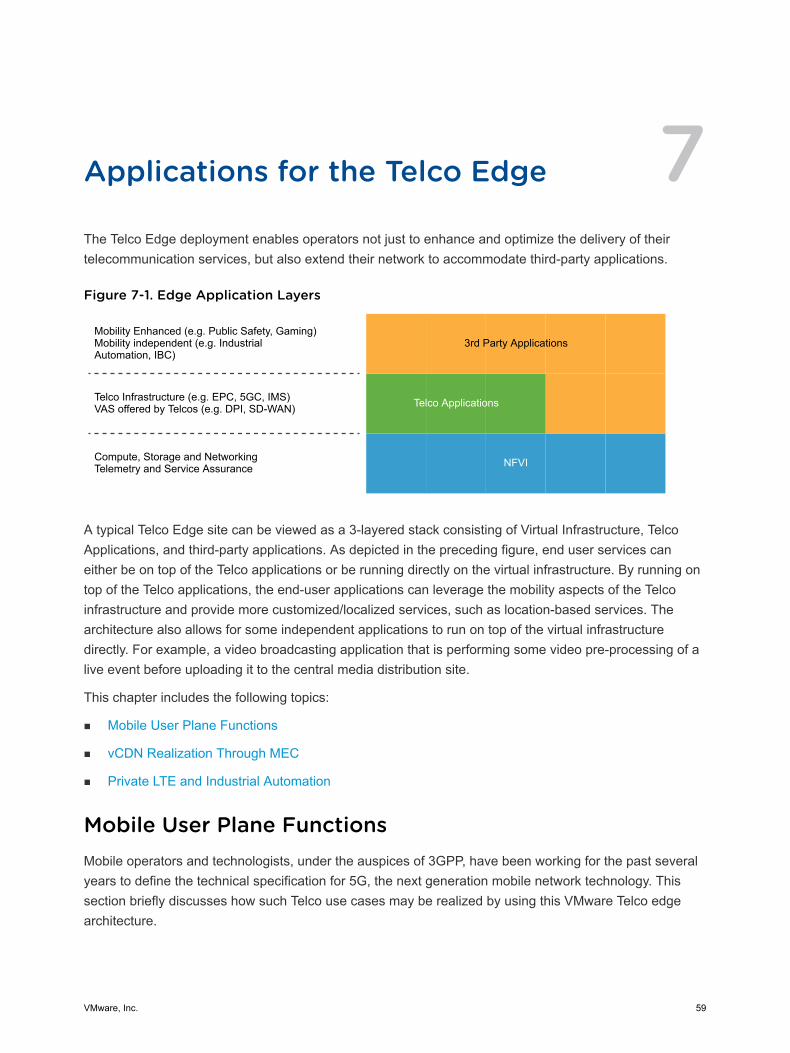
Applications for the Telco Edge 7The Telco Edge deployment enables operators not just to enhance and optimize the delivery of theirtelecommunication services, but also extend their network to accommodate third-party applications.
Figure 7-1. Edge Application Layers
3rd Party ApplicationsMobility Enhanced (e.g. Public Safety, Gaming) Mobility independent (e.g. Industrial Automation, IBC)
Telco Infrastructure (e.g. EPC, 5GC, IMS)VAS offered by Telcos (e.g. DPI, SD-WAN)
Compute, Storage and Networking Telemetry and Service Assurance
Telco Applications
NFVI
A typical Telco Edge site can be viewed as a 3-layered stack consisting of Virtual Infrastructure, TelcoApplications, and third-party applications. As depicted in the preceding figure, end user services caneither be on top of the Telco applications or be running directly on the virtual infrastructure. By running ontop of the Telco applications, the end-user applications can leverage the mobility aspects of the Telcoinfrastructure and provide more customized/localized services, such as location-based services. Thearchitecture also allows for some independent applications to run on top of the virtual infrastructuredirectly. For example, a video broadcasting application that is performing some video pre-processing of alive event before uploading it to the central media distribution site.
This chapter includes the following topics:
n Mobile User Plane Functions
n vCDN Realization Through MEC
n Private LTE and Industrial Automation
Mobile User Plane FunctionsMobile operators and technologists, under the auspices of 3GPP, have been working for the past severalyears to define the technical specification for 5G, the next generation mobile network technology. Thissection briefly discusses how such Telco use cases may be realized by using this VMware Telco edgearchitecture.
VMware, Inc. 59
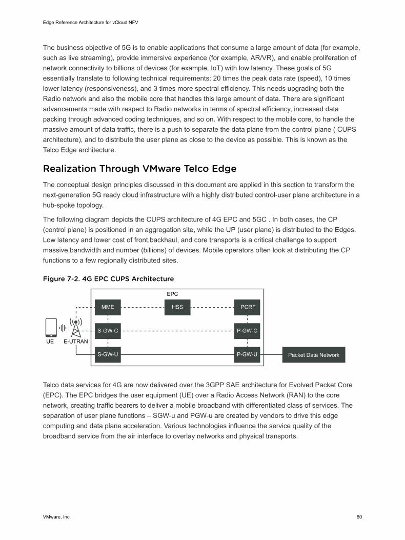
The business objective of 5G is to enable applications that consume a large amount of data (for example,such as live streaming), provide immersive experience (for example, AR/VR), and enable proliferation ofnetwork connectivity to billions of devices (for example, IoT) with low latency. These goals of 5Gessentially translate to following technical requirements: 20 times the peak data rate (speed), 10 timeslower latency (responsiveness), and 3 times more spectral efficiency. This needs upgrading both theRadio network and also the mobile core that handles this large amount of data. There are significantadvancements made with respect to Radio networks in terms of spectral efficiency, increased datapacking through advanced coding techniques, and so on. With respect to the mobile core, to handle themassive amount of data traffic, there is a push to separate the data plane from the control plane ( CUPSarchitecture), and to distribute the user plane as close to the device as possible. This is known as theTelco Edge architecture.
Realization Through VMware Telco EdgeThe conceptual design principles discussed in this document are applied in this section to transform thenext-generation 5G ready cloud infrastructure with a highly distributed control-user plane architecture in ahub-spoke topology.
The following diagram depicts the CUPS architecture of 4G EPC and 5GC . In both cases, the CP(control plane) is positioned in an aggregation site, while the UP (user plane) is distributed to the Edges.Low latency and lower cost of front,backhaul, and core transports is a critical challenge to supportmassive bandwidth and number (billions) of devices. Mobile operators often look at distributing the CPfunctions to a few regionally distributed sites.
Figure 7-2. 4G EPC CUPS Architecture
E-UTRAN
MME HSS
EPC
PCRF
S-GW-C P-GW-C
S-GW-U P-GW-U Packet Data Network
UE
Telco data services for 4G are now delivered over the 3GPP SAE architecture for Evolved Packet Core(EPC). The EPC bridges the user equipment (UE) over a Radio Access Network (RAN) to the corenetwork, creating traffic bearers to deliver a mobile broadband with differentiated class of services. Theseparation of user plane functions – SGW-u and PGW-u are created by vendors to drive this edgecomputing and data plane acceleration. Various technologies influence the service quality of thebroadband service from the air interface to overlay networks and physical transports.
Edge Reference Architecture for vCloud NFV
VMware, Inc. 60

Figure 7-3. 5GC Software Architecture
(R)AN
NSSF NEF NRF PCF UDM AF
AUSF AMF SMF
UPF
SMSF
5GC
Packet Data Network
UE
The following figure shows an example use case for the conceptual deployment of 5GC components ontothe vCloud NFV Edge infrastructure. All the management components are deployed in the Core datacenter, however these are bifurcated as one set of compomemts to manage the workloads deployed atthe Core data center and another set to manage the workloads that are deployed at the edge site, asalready described earlier in this document.
Edge Reference Architecture for vCloud NFV
VMware, Inc. 61
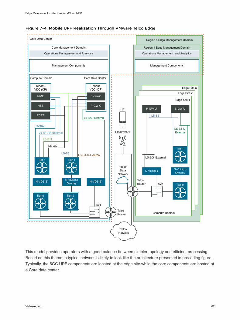
Figure 7-4. Mobile UPF Realization Through VMware Telco Edge
Core Data Center
Operations Management and Analytics
Core Management Domain Region 1 Edge Management Domain
Region n Edge Management Domain
Management Components
Compute Domain Core Data Center
Tenant VDC (CP)
MME
HSS
PCRF
Tenant VDC (DP)
S-GW-C
P-GW-C
Compute Domain
Edge Site 1
Edge Site 2
Edge Site n
S-GW-UP-GW-U
LS-SGi-External
LS-S1-U- External
LS-S5
LS-SGi-External
UE
UE-UTRAN
LS-S1-U-External
LS-S1-AP-External
LS-GX
LS-S6a
LS-S5
LS-S11
ToR
ToR
Telco Router
PacketData
Network
Telco Router
Operations Management and Analytics
Management Components
Tier-1
Tier-0 Tier-0
Tier-1
Telco Network
N-VDS(S) OverlayN-VDS(E)
Tier-0
Tier-1
N-VDS(S) N-VDS(S) Overlay N-VDS(E)
This model provides operators with a good balance between simpler topology and efficient processing.Based on this theme, a typical network is likely to look like the architecture presented in preceding figure.Typically, the 5GC UPF components are located at the edge site while the core components are hosted ata Core data center.
Edge Reference Architecture for vCloud NFV
VMware, Inc. 62

vCDN Realization Through MECAn important new revenue opportunity for Telco Operators with the 5G networks is with Mobile EdgeComputing Platform, alternatively known as MEC. With MEC Platform, operators can dynamically runthird-party applications at the Edge of the network to deliver more value to the customer and drive higherrevenues.
The MEC platform also exposes mobility characteristics of the end device (UE) to the application, therebyenabling more advanced use cases. For example, a gaming application can customize the screen basedon the real-time location of the end user and provide a better user experience. A Content DeliveryNetwork (CDN) is a distributed system positioned throughout the network that places popular contentsuch as streaming video at locations closer to the user than are possible with a traditional centralizeddata center. When using infrastructure edge computing, CDN nodes operate in software at edge datacenters. When instantiated as a virtualized CDN (vCDN), it can operate across a range of virtualizedinfrastructures from Core data center to every Edge data center and it can fully support all types ofvirtualized network function deployment at different operator network vantage points.
With latest processors supporting multiple VMs, a CDN function used for delivering video can run in oneVM while other services can operate in different VMs on the same physical server. Because this modelallows operators to better utilize server resources, a virtualized CDN can be more cost effective than aCDN running on a dedicated infrastructure. Thoughe vCDN addresses cost, it still does not solvechallenges related to capacity planning, agility, or quality.
To solve these challenges, operator networks are typically structured as a hierarchy, beginning with corenetwork and large centralized data centers, extending to regional aggregation networks and data centers,and finally reaching last mile access networks. Small PoPs are located close to subscribers that reside atthe Edge DC whenever needed so that the vCDN component can be placed accordingly. The full vCDNimplementation has to incorporate with four foundational components: virtualized infrastructure, policy-driven orchestration, Software Defined Networks (automation of CDN network configuration anddeployment), and Analytics. Edge Reference Architecture relies on NFV stack from VMware and canaddress the requirements from vCDN.
In recent years, online video consumption over the mobile network has increased manifold due to severalreasons:
n Availability of popular content from online video sources, such as Netflix, Hulu, and YouTube.
n Popularity and demand for live streaming of sporting events, concerts, an so on.
n Advancements in the display technology resulting in larger video streams to support increasedresolution of HD, 4K, or 8K.
n Unlimited/cheap mobile data plans incentivizing people to access video content on their mobiledevice.
Edge Reference Architecture for vCloud NFV
VMware, Inc. 63
To address this increasing demand for online video consumption, CDN vendors and Telco operators arelooking at a multi-layer Virtualized CDN solution that provides the following key benefits:
n Agile Capacity Allocation: With increasing consumption of live video streams, the demand for videoconsumption is expected to be more dynamic. Forexample, a regional concert might drive the onlinevideo consumption for that event by 3x to 10x in and around that area. However, the actual numbercannot be precisely determined. Therefore, it is important that operators can dynamically allocateadditional capacity depending on the instantaneous demand.
n Consolidated Delivery Platform: CDN requires specific characteristics from the virtual infrastructuresuch as fast and large storage and large and elastic network bandwidth. It is not always possible forTelco Operator to install temporary capacity with CDN characteristic in the Edge for live events.Therefore, to keep the CAPEX low, the operator should be able to standardize on a consistenthardware profile and have the software make the best use of the available hardware.
n Orchestrated vCDN: In a multi-layer Telco Edge architecture, the Near Edge and Far Edge can serveas anchor points for fixed and/or mobile broadband offerings. Because these Edges are going to beremotely managed, are numerous in number, and widely distributed, an Orchestration solution thatleverages a policy driven lifecycle automation capability is essential to deliver the desired benefits.
Private LTE and Industrial AutomationAs real-time analytics and automation increases in manufacturing, it is becoming increasingly importantthat the industry premise provides a reliable and scalable wireless communication mechanism. Howevermaintaining session continuity from inside the premise to outside, In-building coverage and uninterruptedmobility are some of the drawbacks of conventional wireless technologies such as WiFi.
To overcome these challenges, many operators are looking at deploying a dedicated mobile network (4Gor 5G) at the enterprise site. To make the site completely self-sufficient, the Enterprise deploymentincludes all data plane and control plane components required to manage a Telco network. By this, noneof the mobile session leaves the Enterprise premise unless necessary. In addition, many Enterprises maydeploy additional applications in the Edge Site. Sometimes, the Edge can also be directly connected tothe Enterprise IT cloud. In terms of requirements, this is similar to the distributed 4G/5G mobile core.
Edge Reference Architecture for vCloud NFV
VMware, Inc. 64

Authors and Contributors 8The following authors co-wrote this paper:
n Arunkumar Kodagi Ramachandra, Solutions Architect, NFV Solutions Engineering, VMware
n Indranil Bal, Solution Consultant, NFV Solutions, VMware
n Ramki Krishnan, Lead Technologist, OpenSource NFV, NFV Solutions, VMware
n Ramkumar Venketaramani, Director Product Management, NFV Solutions, VMware
n Sumit Verdi, Director Lighthouse Solutions, NFV Solutions, VMware
n T. Sridhar, Principal Engineer & Chief Architect, NFV Solutions, VMware
n Tuan Nguyen, Senior Solutions Engineer, NFV Solutions, VMware
Many thanks for contributions from:
n Andrea Li, Lead Solutions Test Architect, NFV Solutions Engineering, VMware
n Danny Lin, Sr. Director Product Management and Architecture, NFV Solutions, VMware
n Jambi Ganbar, Sr. Technical Solutions Manager, NFV Solutions Engineering, VMware
n Kandasamy M, Graphic Designer, Content Strategy & Ops, VMware
n Michelle Han, Director, Solutions Testing and Validation, NFV Solutions Engineering, VMware
n Viji Subramaniam, Program Manager, Information Experience, VMware
Special thanks for their valuable feedback to:
n Arul Dharmalingam, Christian Hasner, Dharma Rajan, Gary Day, Frank Escaros-Buechsel, GaryKotton, Giridhar Jayavelu, Henrik Blixt, Henrik Oberg, Marcos Hernandez, Mark Voelker, MauricioValdueza, Mikael Brihed, Mike Richer, Mustafa Bayramov, Neil Moore, Pradip Kadam, Phil Kippen,Revathi Govindarajan, Richard Boswell, Sudesh Tendulkar, Suresh Babu Nekkalapudi.
VMware, Inc. 65