
vCloud NFV Reference Architecture - VMware vCloud NFV 2 · OSS/BSS Working Domain VNF Working...
60
vCloud NFV Reference Architecture VMware vCloud NFV 2.0
Transcript of vCloud NFV Reference Architecture - VMware vCloud NFV 2 · OSS/BSS Working Domain VNF Working...
vCloud NFV ReferenceArchitectureVMware vCloud NFV 2.0
vCloud NFV Reference Architecture
VMware, Inc. 2
You can find the most up-to-date technical documentation on the VMware website at:
https://docs.vmware.com/
If you have comments about this documentation, submit your feedback to
Copyright © 2017–2018 VMware, Inc. All rights reserved. Copyright and trademark information.
VMware, Inc.3401 Hillview Ave.Palo Alto, CA 94304www.vmware.com
Contents
1 About vCloud NFV Reference Architecture 4
2 Network Functions Virtualization Overview 5
3 Communication Service Provider Requirements 8
Automated Service Delivery 8
Operational Intelligence 9
Carrier Grade 10
4 Solution Overview 11
Technology Mapping 11
NFVI Components Overview 13
MANO Components Overview 16
Operations Management Components 18
Virtual Network Functions and VMware vCloud NFV 21
5 Reference Architecture 22
Design Principles 22
Two-Pod Design Overview 26
Three-Pod Design Overview 38
Operations Management 48
Carrier Grade 56
6 Authors and Contributors 60
VMware, Inc. 3
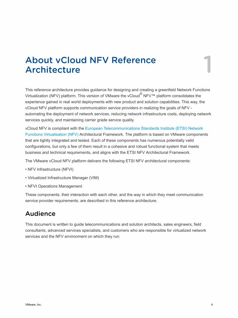
About vCloud NFV ReferenceArchitecture 1This reference architecture provides guidance for designing and creating a greenfield Network FunctionsVirtualization (NFV) platform. This version of VMware the vCloud® NFV™ platform consolidates theexperience gained in real world deployments with new product and solution capabilities. This way, thevCloud NFV platform supports communication service providers in realizing the goals of NFV -automating the deployment of network services, reducing network infrastructure costs, deploying networkservices quickly, and maintaining carrier grade service quality
vCloud NFV is compliant with the European Telecommunications Standards Institute (ETSI) NetworkFunctions Virtualisation (NFV) Architectural Framework. The platform is based on VMware componentsthat are tightly integrated and tested. Each of these components has numerous potentially validconfigurations, but only a few of them result in a cohesive and robust functional system that meetsbusiness and technical requirements, and aligns with the ETSI NFV Architectural Framework.
The VMware vCloud NFV platform delivers the following ETSI NFV architectural components:
• NFV Infrastructure (NFVI)
• Virtualized Infrastructure Manager (VIM)
• NFVI Operations Management
These components, their interaction with each other, and the way in which they meet communicationservice provider requirements, are described in this reference architecture.
AudienceThis document is written to guide telecommunications and solution architects, sales engineers, fieldconsultants, advanced services specialists, and customers who are responsible for virtualized networkservices and the NFV environment on which they run.
VMware, Inc. 4
Network FunctionsVirtualization Overview 2NFV is an architectural framework that is developed by the ETSI NFV Industry Specification Group. Theframework aims to transform the telecommunications industry through lower costs, rapid innovation, andscale.
The NFV framework provides a standardized model that moves away from proprietary, purpose-builthardware that is dedicated to a single service, toward network functions that are delivered throughsoftware virtualization as virtual network functions (VNFs) with commercial off-the-shelf (COTS)hardware. The result is a network that is more agile and better able to respond to the on-demand,dynamic needs of telecommunications traffic and services. The framework identifies functional blocks andthe main reference points between these blocks. Some of these are already present in currentdeployments, while others need to be added to support the virtualization process and operation.
The ETSI NFV Architectural Framework diagram depicts the functional blocks and reference points in theNFV framework. Each functional block is shown by solid lines and is within the scope of NFV. Thearchitectural framework is complemented by the NFVI Operations Management functional block, which isnot part of the standard framework. This block is essential to run a production platform. The OperationsManagement functional block is separated from the Virtualized Infrastructure Manager (VIM) based onbest practices and deployment experience. The architectural framework focuses on the functions andcapabilities that are necessary for the virtualization and operation of a CSP's network. Functional blocksabove the dotted line are not in the scope of this paper.
VMware, Inc. 5
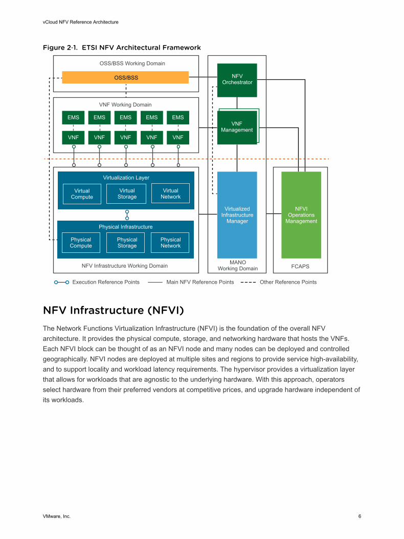
Figure 2‑1. ETSI NFV Architectural Framework
NFVOrchestrator
VNFManagement
VirtualizedInfrastructure
Manager
NFVIOperations
Management
VirtualCompute
VirtualStorage
VirtualNetwork
PhysicalCompute
PhysicalStorage
PhysicalNetwork
MANOWorking Domain
Virtualization Layer
Main NFV Reference Points Other Reference PointsExecution Reference Points
VNFVNF
EMS EMSEMSEMSEMS
FCAPS
OSS/BSS Working Domain
VNF Working Domain
OSS/BSS
Physical Infrastructure
VNF VNFVNF
NFV Infrastructure Working Domain
NFV Infrastructure (NFVI)The Network Functions Virtualization Infrastructure (NFVI) is the foundation of the overall NFVarchitecture. It provides the physical compute, storage, and networking hardware that hosts the VNFs.Each NFVI block can be thought of as an NFVI node and many nodes can be deployed and controlledgeographically. NFVI nodes are deployed at multiple sites and regions to provide service high-availability,and to support locality and workload latency requirements. The hypervisor provides a virtualization layerthat allows for workloads that are agnostic to the underlying hardware. With this approach, operatorsselect hardware from their preferred vendors at competitive prices, and upgrade hardware independent ofits workloads.
vCloud NFV Reference Architecture
VMware, Inc. 6
Management and Orchestration (MANO)The Management and Orchestration (MANO) functional block is responsible for the management of allthe resources in the infrastructure along with the orchestration and life cycle management of VNFs.These elements support the infrastructure virtualization and life cycle management of MANO VNFs, witha focus on the virtualization specific management tasks necessary to the NFV framework.
VirtualizedInfrastructure Manager(VIM)
The Virtualized Infrastructure Manager (VIM) is a functional block of theMANO and is responsible for controlling, managing, and monitoring theNFVI compute, storage, and network hardware, the software for thevirtualization layer, and the virtualized resources. The VIM manages theallocation and release of virtual resources, and the association of virtual tophysical resources, including the optimization of resources. The completeinventory of the NFVI is maintained in the VIM, including the linkage andrelationship between components as they relate to an instance of a VNFworkload, to allow for monitoring in the context of a single VNF.
Virtual NetworkFunctions Manager(VNFM)
This document does not cover the Virtual Network Functions Manager(VNFM) functional block. For information about the VNFM functional block,refer to the publicly available ETSI NFV Standards.
Network FunctionsVirtualizationOrchestrator (NFVO)
This document does not cover the NFV Orchestrator (NFVO) functionalblock. For information about the NFVO functional block, refer to the publiclyavailable ETSI NFV Standards
Virtualized Network Functions (VNFs)This document does not cover the Virtualized Network Function (VNF) working domain. For informationabout the VNF working domain, refer to the publicly available ETSI NFV Standards
Operations Support Systems and Business SupportSystems (OSS/BSS)The vCloud NFV OpenStack Edition platform exposes APIs that can be consumed from one or multipleoperations support systems and business support systems (OSS/BSS). These are not described in thisdocument. For information about APIs that can be consumed from the OSS/BSS working domain, refer tothe publicly available ETSI NFV Standards.
vCloud NFV Reference Architecture
VMware, Inc. 7

Communication ServiceProvider Requirements 3More and more Communication Service Providers (CSPs) are using vCloud NFV to embark on a journeyto modernize and transform networks and services with virtualized software components. Collectedrequirements help shape the current and future releases of the vCloud NFV solution. These keyrequirements are introduced in this section and will be discussed in detail in the Reference Architecturesection of this document. CSPs have specific requirements of NFVI, VIM, and FCAPS elements, basedon the need to demonstrate progress in an NFV deployment while generating revenue from the virtualdomain. For this reason, a great deal of focus is given to the ability to easily, programmatically, andrepeatedly deploy services from a service component catalog. Since CSPs deliver services that are oftenregulated by local governments, carrier grade aspects of these services, such as high availability anddeterministic performance, are also included in this list. CSPs must ensure that managing the NFVI andthe deployed virtualized network functions is tightly integrated in the solution. The following sectionsexplain the requirements in further detail.
This chapter includes the following topics:
n Automated Service Delivery
n Operational Intelligence
n Carrier Grade
Automated Service DeliveryOne of the benefits of virtualization is the ability to centrally orchestrate the deployment of service buildingblocks from a software catalog, as opposed to using proprietary appliances. Instead of sending engineersto a site to install physical devices, Virtual Network Functions (VNFs), also known as service components,are selected from a catalog. By clicking a button, the new service is installed.
To reach this level of simplicity, the NFV platform must support the following:
n Quick VNF Onboarding. VNF onboarding is automated using enhanced, policy based vApptemplating and declarative abstract resource requirements for underlying compute, storage, andnetworking resources.
n Programmatic VNF Provisioning: The speed and efficiency of VNF deployment is increased throughautomation, selecting service operations from a catalog of VNFs to deploy specific services.
VMware, Inc. 8
n True Multitenant Isolation. Physical resources abstracted into virtual resource pools are sharedbetween services and customers, referred to as tenants of the platform. The ability to partition theservice and VNF from each other is key to ensure performance and quality of service (QoS) acrossthe platform
n Service Life Cycle Management. Programmatic service creation and dynamic orchestration of runningVNFs are required pieces of an automation framework. Interfaces between the VIM, the VNFM, andthe NFV Orchestrator (NFVO) must leverage a robust and open API. Using these interfaces the NFVplatform deploys, scales, restarts, and decommissions VNFs as needed
n Dynamic Optimization. As more and more VNFs are deployed on the NFVI, NFVI resources must beable to proactively act on specific operations. Since the NFV environment is software based, thesystem must be able to move VNF components to balance fair and optimized resource utilization.NFVI resiliency is improved with proactive monitoring and automation - from scalability of resourcepools to avoid issues, to policy based workload placement
Operational IntelligenceBuilding an NFVI and managing VNFs effectively is a primary requirement for all CSPs. Operation andmanagement of the NFV environment must be tightly integrated with the other benefits of the solution.
The functions CSPs require include:
n Discovery and Reconciliation. The NFV platform must automatically discover the network and servicetopologies across the physical and virtual domains, and reconcile runtime states as they change. TheNFVI, VNFs, and VNF components (VNFCs) must be entirely visible to the operating personnel.
n Performance and Capacity Monitoring. Continuous system performance monitoring must provide aholistic view of key performance indicators such as interface utilization, data rates, capacity demand,service-level agreement (SLA) violations, and component availability. The same system must beintelligent and provide capacity and performance forecasts with actionable recommendations.
n Issue Isolation and Remediation. The platform must provide near real-time root cause analysis, andmeaningful alerting for fast remediation and proactive issue avoidance.
n Workflow Automation and Expansion.The monitoring platform must be expandable to allowintegration with new data source consumption and coexistence with other elements such as OSS,service orchestration, service assurance, and big data analytics. Where possible, the monitoringsystem must provide a way to add third-party expansion modules for higher layer monitoring, such asVoIP and video quality
vCloud NFV Reference Architecture
VMware, Inc. 9
Carrier GradeCSPs deliver certain services that are considered critical to infrastructure and are therefore tightlyregulated by many governments. These regulations force a level of service quality to which over-the-top(OTT) providers do not adhere. CSPs must conform to specific service quality metrics, for exampleresolving service disruptions quickly and automatically without packet loss affecting service quality. Thesame applies to services offered from a CSP to enterprise customers. Service quality is at the core ofbrand protection and customer experience management. As such, SLAs require the delivery of carriergrade quality services.
The following examples are essential NFV platform requirements for carrier grade systems.
n High Availability and Resiliency. The platform must provide integrated high availability and faulttolerance across the NFVI, virtual, and management domains. In the event of a failure, the platformmust be able to self-heal to maximize service uptime. Mean Time To Failure (MTTF) must increaseover the lifetime of the platform through adaptive, proactive, and automated monitoring systems.Mean Time To Repair (MTTR) must decrease over the lifetime of the NFV environment, as the systemis optimized and proactive alerting takes place.
n Performance. The platform must achieve deterministic performance. The amount of resourcesrequired to deliver a certain level of performance must be well understood. Data plane intensive VNFsmust be supported by the same components as control and management plane VNFs.
n Scalability. CSPs expect growth in the number of customers and services deployed on the NFVplatform. The platform must be able to provide long term scale out capabilities, and dynamic andshort term scale up and scale out functions.
n NFVI Life Cycle (Patching and Upgrades). The platform must be patched and upgraded by usingoptimized change management approaches for zero to minimal downtime.
vCloud NFV Reference Architecture
VMware, Inc. 10
Solution Overview 4The VMware vCloud NFV 2.0 platform is an evolution of the VMware NFV solution, based on extensivecustomer deployment and the continued development of standards organizations such as the EuropeanTelecommunications Standards Institute (ETSI). The vCloud NFV platform provides a comprehensive,service-oriented solution, leveraging a cloud computing model that allows ubiquitous, programmatic, on-demand access to a shared pool of compute, network, and storage resources. The solution is integratedwith holistic operations management and service assurance capabilities, empowering the operator torapidly deliver services while ensuring their quality. With a fully integrated VIM, the same vCloud NFVinfrastructure delivers a myriad of telecommunications use cases, and facilitates reusability of the servicecatalog based VNFs.
The vCloud NFV platform delivers a complete, integrated solution that has been rigorously tested toensure compatibility, robustness, and functionality. Components used in creating the solution are currentlydeployed across many industries and scenarios. vCloud NFV software components can be used in avariety of ways to construct a comprehensive, end-to-end solution that meets the business goals ofCSPs. This document discusses one way components can be used to create a vCloud NFV architecture.
This chapter includes the following topics:
n Technology Mapping
n NFVI Components Overview
n MANO Components Overview
n Operations Management Components
n Virtual Network Functions and VMware vCloud NFV
Technology MappingThe vCloud NFV platform is an ETSI compliant, fully integrated, modular, multitenant NFV platform. Itmeets the ETSI NFV framework, which covers the virtualization layer of the NFVI and the VIM. vCloudNFV expands on the ETSI NFV framework by integrating robust operations management and intelligencecomponents to provide the operator with complete platform visibility and monitoring functionality.
This document focuses on the NFVI layer, the VIM components, and the NFV platform operationsmanagement. Figure 2 depicts the mapping between the vCloud NFV functional elements and the ETSINFV reference model.
VMware, Inc. 11
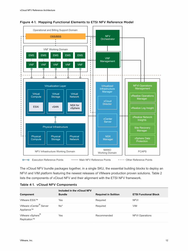
Figure 4‑1. Mapping Functional Elements to ETSI NFV Reference Model
Virtualization Layer
EMS
NFVOrchestrator
VNFManagement
VirtualizedInfrastructure
Manager
NFVI OperationsManagement
MANOWorking Domain
VirtualCompute
VirtualStorage
VirtualNetwork
PhysicalCompute
PhysicalStorage
PhysicalNetwork
vCenterServer
NSXManager
VNF VNFVNFVNFVNF
EMS EMSEMSEMS
VNF Working Domain
NFV Infrastructure Working Domain FCAPS
Operational and Billing Support Domain
OSS/BSS
Main NFV Reference Points Other Reference PointsExecution Reference Points
vRealize OperationsManager
vRealize Log Insight
vRealize NetworkInsights
vSphere DataProtection
Site RecoveryManager
Physical Infrastructure
vSANESXi
vCloudDirector NSX for
vSphere
The vCloud NFV bundle packages together, in a single SKU, the essential building blocks to deploy anNFVI and VIM platform featuring the newest releases of VMware production proven solutions. Table 2lists the components of vCloud NFV and their alignment with the ETSI NFV framework.
Table 4‑1. vCloud NFV Components
ComponentIncluded in the vCloud NFVBundle Required in Solition ETSI Functional Block
VMware ESXi™ Yes Required NFVI
VMware vCenter® ServerAppliance™
No* Required VIM
VMware vSphere®
Replication™Yes Recommended NFVI Operations
vCloud NFV Reference Architecture
VMware, Inc. 12
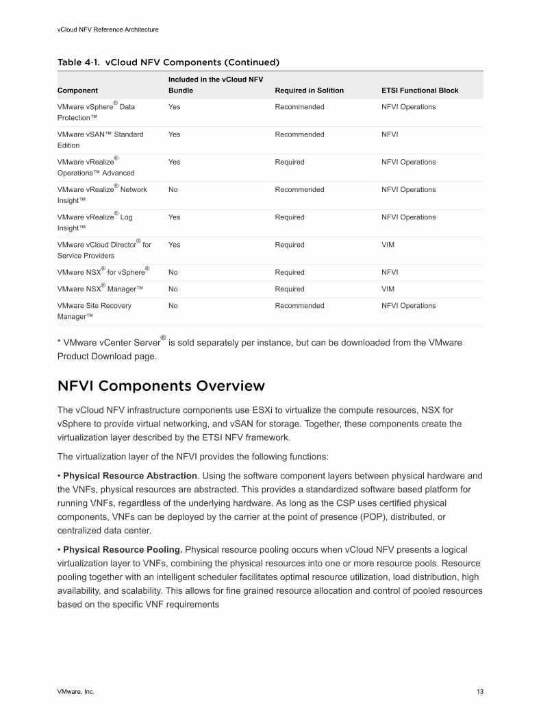
Table 4‑1. vCloud NFV Components (Continued)
ComponentIncluded in the vCloud NFVBundle Required in Solition ETSI Functional Block
VMware vSphere® DataProtection™
Yes Recommended NFVI Operations
VMware vSAN™ StandardEdition
Yes Recommended NFVI
VMware vRealize®
Operations™ AdvancedYes Required NFVI Operations
VMware vRealize® NetworkInsight™
No Recommended NFVI Operations
VMware vRealize® LogInsight™
Yes Required NFVI Operations
VMware vCloud Director® forService Providers
Yes Required VIM
VMware NSX® for vSphere® No Required NFVI
VMware NSX® Manager™ No Required VIM
VMware Site RecoveryManager™
No Recommended NFVI Operations
* VMware vCenter Server® is sold separately per instance, but can be downloaded from the VMwareProduct Download page.
NFVI Components OverviewThe vCloud NFV infrastructure components use ESXi to virtualize the compute resources, NSX forvSphere to provide virtual networking, and vSAN for storage. Together, these components create thevirtualization layer described by the ETSI NFV framework.
The virtualization layer of the NFVI provides the following functions:
• Physical Resource Abstraction. Using the software component layers between physical hardware andthe VNFs, physical resources are abstracted. This provides a standardized software based platform forrunning VNFs, regardless of the underlying hardware. As long as the CSP uses certified physicalcomponents, VNFs can be deployed by the carrier at the point of presence (POP), distributed, orcentralized data center.
• Physical Resource Pooling. Physical resource pooling occurs when vCloud NFV presents a logicalvirtualization layer to VNFs, combining the physical resources into one or more resource pools. Resourcepooling together with an intelligent scheduler facilitates optimal resource utilization, load distribution, highavailability, and scalability. This allows for fine grained resource allocation and control of pooled resourcesbased on the specific VNF requirements
vCloud NFV Reference Architecture
VMware, Inc. 13
• Physical Resource Sharing. In order to truly benefit from cloud economies, the resources pooled andabstracted by a virtualization layer must be shared between various network functions. The virtualizationlayer provides the functionality required for VNFs to be scheduled on the same compute resources,collocated on shared storage, and to have network capacity divided among them. The virtualization layeralso ensures fairness in resource utilization and usage policy enforcement.
The following components constitute the virtualization layer in the NFVI domain:
Compute - VMware ESXiESXi is the hypervisor software used to abstract physical x86 server resources from the VNFs. Eachcompute server is referred to as a host in the virtual environment. ESXi hosts are the fundamentalcompute building blocks of vCloud NFV. ESXi host resources can be grouped together to provide anaggregate set of resources in the virtual environment, called a cluster. Clusters are used to logicallyseparate between management components and VNF components and are discussed at length in theReference Architecture section of this document.
ESXi is responsible for carving out resources needed by VNFs and services. ESXi is also theimplementation point of policy based resource allocation and separation, through the use of VMwarevSphere® Distributed Resource Scheduler™ (DRS), an advanced scheduler which balances and ensuresfairness in resource usage in a shared environment.
Since ESXi hosts VNF components in the form of virtual machines (VMs), it is the logical place toimplement VM based high availability, snapshotting, migration with VMware vSphere ® vMotion®, filebased backups, and VM placement rules. ESXi hosts are managed by vCenter Server Appliance,described as one of the VIM components in the VIM Components section of this document.
An example of one of the new high availability mechanisms available with VMware vCloud NFV 2.0 isProactive High Availability (HA). While VMware vSphere® High Availability can rapidly restore VNFcomponents if a host fails, Proactive HA has tighter integration with several server health monitoringsystems, which means that VNF components can be migrated away from a host whose health isdegrading. This function is realized using vSphere vMotion to move live, running workloads to healthyhosts. vSphere vMotion is also used to facilitate maintenance tasks and load balancing among hosts in acluster, with no or minimal service disruption.
Storage - VMware vSANvSAN is the native vSphere storage component in the NFVI virtualization layer, providing a sharedstorage pool between hosts in the cluster. With vSAN, storage is shared by aggregating the local disksand flash drives attached to the host. Although third-party storage solutions with storage replicationadapters that meet VMware storage compatibility guidelines are also supported, this referencearchitecture discusses only the vSAN storage solution.
It is a best practice recommendation that each cluster within vCloud NFV is configured to use a sharedstorage solution. When hosts in a cluster use shared storage, manageability and agility improve.
vCloud NFV Reference Architecture
VMware, Inc. 14
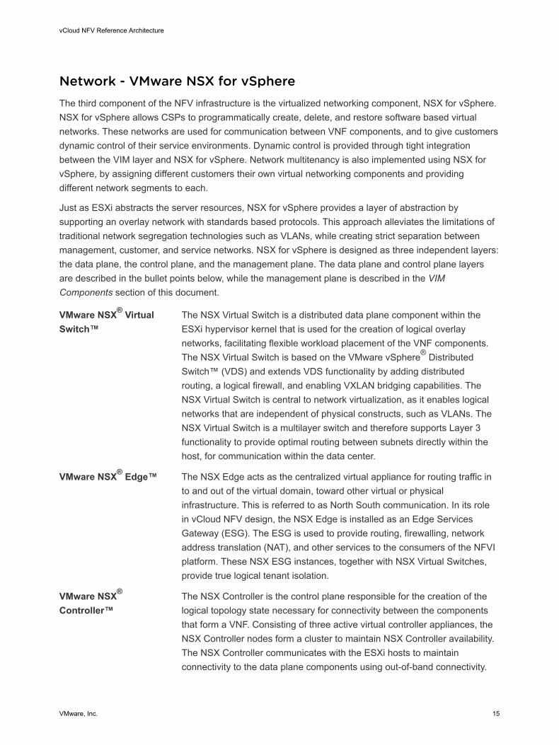
Network - VMware NSX for vSphereThe third component of the NFV infrastructure is the virtualized networking component, NSX for vSphere.NSX for vSphere allows CSPs to programmatically create, delete, and restore software based virtualnetworks. These networks are used for communication between VNF components, and to give customersdynamic control of their service environments. Dynamic control is provided through tight integrationbetween the VIM layer and NSX for vSphere. Network multitenancy is also implemented using NSX forvSphere, by assigning different customers their own virtual networking components and providingdifferent network segments to each.
Just as ESXi abstracts the server resources, NSX for vSphere provides a layer of abstraction bysupporting an overlay network with standards based protocols. This approach alleviates the limitations oftraditional network segregation technologies such as VLANs, while creating strict separation betweenmanagement, customer, and service networks. NSX for vSphere is designed as three independent layers:the data plane, the control plane, and the management plane. The data plane and control plane layersare described in the bullet points below, while the management plane is described in the VIMComponents section of this document.
VMware NSX® VirtualSwitch™
The NSX Virtual Switch is a distributed data plane component within theESXi hypervisor kernel that is used for the creation of logical overlaynetworks, facilitating flexible workload placement of the VNF components.The NSX Virtual Switch is based on the VMware vSphere® DistributedSwitch™ (VDS) and extends VDS functionality by adding distributedrouting, a logical firewall, and enabling VXLAN bridging capabilities. TheNSX Virtual Switch is central to network virtualization, as it enables logicalnetworks that are independent of physical constructs, such as VLANs. TheNSX Virtual Switch is a multilayer switch and therefore supports Layer 3functionality to provide optimal routing between subnets directly within thehost, for communication within the data center.
VMware NSX® Edge™ The NSX Edge acts as the centralized virtual appliance for routing traffic into and out of the virtual domain, toward other virtual or physicalinfrastructure. This is referred to as North South communication. In its rolein vCloud NFV design, the NSX Edge is installed as an Edge ServicesGateway (ESG). The ESG is used to provide routing, firewalling, networkaddress translation (NAT), and other services to the consumers of the NFVIplatform. These NSX ESG instances, together with NSX Virtual Switches,provide true logical tenant isolation.
VMware NSX®
Controller™The NSX Controller is the control plane responsible for the creation of thelogical topology state necessary for connectivity between the componentsthat form a VNF. Consisting of three active virtual controller appliances, theNSX Controller nodes form a cluster to maintain NSX Controller availability.The NSX Controller communicates with the ESXi hosts to maintainconnectivity to the data plane components using out-of-band connectivity.
vCloud NFV Reference Architecture
VMware, Inc. 15
MANO Components OverviewThe ETSI NFV Management and Orchestration (MANO) framework consists of three functional blocks:the Virtualized Infrastructure Manager (VIM), the NFV Orchestrator (NFVO), and the VNF Manager(VNFM). The vCloud NFV platform includes an integrated VIM, which exposes well documentednorthbound interfaces to VNFMs and NFVOs. VNFM components are often packaged together withVNFs.
NFVO partners and independent VNFM solutions are listed on the Telecommunication Solutions page.
VIM ComponentsThree components form the VIM functionality in vCloud NFV: the vCenter Server Appliance, the NSXManager, and the vCloud Director for Service Providers. vCloud Director is the top level VIM component.It leverages the vCenter Server Appliance and the NSX Manager to perform VIM functionality. vCloudDirector, vCenter Server Appliance, and the NSX Manager are layered in a hierarchical fashion tofacilitate the separation of roles and responsibilities in the CSP networks and to increase overall systemresiliency.
vCloud NFV Reference Architecture
VMware, Inc. 16

Figure 4‑2. VIM Hierarchy in VMware vCloud NFV
Virtualized Infrastructure Manager
vCloud Director
NSX Manager
vCenter ServerAppliance
Provider vDCs /Organization vDCs
Disks External Networks / Network Pools /OvDC Networks / vApp Networks /
Edge Gateways
Host Clusters / Resource Pools
Datastores / Datastore Clusters
Virtual Switches / Port Groups / Virtual Routers /
Logical Switches
Compute / Memory
Storage Network
Physical
Storage
Network
Compute
VMware vCloud DirectorvCloud Director is an abstraction layer that operates on top of the other virtualized infrastructure managercomponents, vCenter Server and NSX Manager. vCloud Director builds secure, multitenant virtualenvironments by pooling virtual infrastructure resources into virtual data centers and exposing them tousers through Web based portals and programmatic interfaces as fully automated, catalog basedservices.
A fundamental concept in vCloud Director is that of the tenant. A tenant is a logically isolated constructrepresenting a customer, department, network function, or service, used to deploy VNF workloads.vCloud Director isolates administrative boundaries into NFVI tenants. VNF workload resourceconsumption is therefore segregated from other VNF workloads, even though the VNFs may share thesame resources.
vCloud NFV Reference Architecture
VMware, Inc. 17
The pooled resources used by vCloud Director are grouped into two abstraction layers:
n Provider Virtual Data Centers. A provider virtual data center (PvDC) combines the compute andmemory resources of a single vCenter Server resource pool with the storage resources of one ormore datastores available to that resource pool. This construct is the highest in the vCloud Directorresource catalog hierarchy.
n Organization Virtual Data Centers. An organization virtual data center (OvDC) provides resources toan NFVI tenant and is partitioned from a provider virtual data center. OvDCs provide an environmentwhere virtual systems can be stored, deployed, and operated. They also provide storage for virtualmedia such as ISO images, VNF templates, and VNF component templates.
vCloud Director implements the open and publicly available vCloud API, which provides compatibility,interoperability, and programmatic extensibility to network equipment providers (NEPs) and their VNFManagers. The vCloud Director capabilities can be extended to create adaptors to external systemsincluding OSS/BSS.
VMware vCenter ServerThe VMware vCenter Server® is the centralized management interface for compute and storageresources in the NFVI. It provides an inventory of allocated virtual to physical resources, managesinventory related information, and maintains an overview of the virtual resource catalogs. vCenter Serveralso collects data detailing the performance, capacity, and state of its inventory objects. vCenter Serverexposes programmatic interfaces to other management components for fine grained control, operation,and monitoring of the underlying virtual infrastructure.
A resource pool is a logical abstraction which aggregates the use of vCenter Server resources. Multipleresource pools, grouped into hierarchies, can be used to partition available CPU and memory resources.The resource pool allows the operator to compartmentalize all resources in a cluster and, if necessary,delegate control over a specific resource pool to other organizations or network functions. The operatorcan also use resource pools to isolate resources used by one service or function from others.
VMware NSX ManagerThe NSX Manager is the primary management plane interface for configuration of network resourceswithin the NFVI. The NSX Manager is responsible for the deployment and management of the virtualizednetwork components, and functions used to support the creation of network services by the VNFs. Suchfunctions include network segments, routing, firewalling, and load balancing, etc.
Operations Management ComponentsThe vCloud NFV solution includes six components that together provide a holistic approach to operationsmanagement functionality for the NFV infrastructure of a Communication Service Provider (CSP).Together, the vRealize Operations, vRealize Log Insight, vRealize Network Insight, Site RecoveryManager, vSphere Replication, and vSphere Data Protection components monitor the health of thevirtualization infrastructure, collect its logs and alarms, correlate events across multiple data sources andcomponents to predict future issues, leverage the policy based automation framework to conductremediation, and analyze data to help with health prediction and capacity planning.
vCloud NFV Reference Architecture
VMware, Inc. 18
The key operations management tasks carried out by these components are:
n NFVI Visibility. NFVI visibility is achieved by collecting key performance and capacity metrics from theentire virtualization layer, the physical devices, and the VIM components. When problems occur, theoperator can uncover the root cause and determine its location quickly, reducing the Mean Time ToRepair (MTTR).
n Fault Collection and Reporting. The components used in the NFV environment, in the physicalinfrastructure, the virtualization layer, or even the VNFs themselves, generate various log messagesand alarms. vCloud NFV includes an integrated log collection system that can correlate betweenalerts and log messages to quickly troubleshoot issues.
n Performance Management and Capacity Planning. Ongoing management of performance andcapacity across the NFVI is required for optimal and economic usage of the platform. Theperformance management capability helps identify degraded performance before VNFs are affected.This leaves the operator with enough time to take corrective measures, increasing the Mean Time ToFailure (MTTF).
n Optimization. The operations management components analyze system usage and proactivelyprovide optimization recommendations, including network topology modifications.
The specific components responsible for operations and management are:
VMware vRealize Operations ManagerVMware vRealize® Operations ManagerTM delivers intelligent operations management with full stackvisibility across physical and virtual infrastructures. Through integrated performance and healthmonitoring functions, vRealize Operations Manager improves system performance, avoids servicedisruption, and helps the CSP provide proactive management of the NFVI infrastructure. The keycapabilities that enable these benefits include predictive analytics, smart and configurable alerts, and userguided remediation. With policy based automation, operations teams automate key processes to improvethe NFV environment operations.
The vRealize Operations Manager extends to collect information through management packs. Informationcollected is filtered for relevancy, analyzed, and presented in the form of customizable dashboards. Themonitoring solution exposes an API that retrieves performance and health data pertaining to the NFVI,and the virtual resources that make up the VNF instance, through an external system.
Out of the box, vRealize Operations Manager does not monitor VNF service availability or VNF internalKPIs. The VNF Manager derives this information through direct interaction with the respective VNFs.However, VNF vendors can write their own management packs, known as plugins in vRealize OperationsManager, to extend functionality to the VNF application. In doing so, the vRealize Operations Managerbecomes a single pane of glass from which the operator manages all components required to construct avirtual network service.
vRealize Operations Manager exposes the information it gathers through an API that can be consumedby OSS/BSS, or integrated directly with other MANO components.
vCloud NFV Reference Architecture
VMware, Inc. 19
VMware vRealize Log InsightvRealize Log Insight delivers heterogeneous and highly scalable log management with intuitive,actionable dashboards, sophisticated analytics, and broad third party extensibility. It provides deepoperational visibility and faster troubleshooting across physical, virtual, and cloud environments. Itsinnovative indexing and machine learning based grouping enables fast log searches that aid in quicklytroubleshooting issues.
vRealize Log Insight ingests large amounts of syslog data from the physical and virtual NFVIcomponents, to deliver near real-time monitoring, search, and log analytics. It automatically identifiesstructure from all types of machine generated log data, including application logs, network traces,configuration files, messages, performance data, and system state dumps to build a high performanceindex for analytics purposes. Coupled with a highly intuitive dashboard for stored queries, reports, andalerts, vRealize Log Insight assists the operator in speedy root cause analysis and reduction in MeanTime To Repair (MTTR).
The vRealize Log Insight API provides programmatic access to vRealize Log Insight functionality, and toits datastore. As a result the OSS/BSS systems or MANO components can integrate with vRealize LogInsight to gain further insight into the system events and logs.
VMware vRealize Network InsightvRealize Network Insight collects metrics, log data, network topology, and event data to provide a detailedview of the network configuration and its health. Information is collected on all NSX managed networks,including East-West traffic between VNF components, and North-South traffic in to and out of the NFVinfrastructure. Broad Layer 2 to Layer 3 support means that vRealize Network Insight can visualize boththe underlay and the overlay networks, providing the operator with a holistic view into all relevant networklayers. Using this information, the operator can optimize network performance and increase its availabilitywith visibility and analytics across all virtual and physical elements.
VMware Site Recovery ManagerSite Recovery Manager works in conjunction with various storage replication solutions, including vSphereReplication, to automate the process of migrating, recovering, testing, and failing back virtual machineworkloads for disaster recovery across multiple sites.
VMware vSphere ReplicationvSphere Replication is a virtual machine data protection and disaster recovery solution. It is fullyintegrated with vCenter Server and VMware vSphere® Web Client, providing host-based, asynchronousreplication of virtual machines including their storage.
vCloud NFV Reference Architecture
VMware, Inc. 20
VMware vSphere Data ProtectionvSphere Data Protection is used for backup and recovery. It is fully integrated with vCenter Server andthe vSphere Web Client, providing disk-based backup of virtual machines and applications. It conservesstorage usage by using standard deduplication techniques
Third-party backup solutions that are certified for use with VMware vSphere can be used instead.
Virtual Network Functions and VMware vCloud NFVvCloud NFV provides VNFs with network, compute, and storage virtual infrastructure resources, for thedeployment and creation of network services.
VMware operates the VMware Ready for NFV accreditation program, in which functional interoperabilitybetween partner VNFs and vCloud NFV virtualization layers and VIMs are tested. The program verifiesthat VNFs can use CSP relevant functionality, available on vCloud NFV, and ensures that the partnerVNFs understand how to use it
VMware maintains a list of VNFs that have participated in the VMware Ready for NFV program and areverified for interoperability with the platform. This list is located on the VMware Solution Exchange (VSX)page.
vCloud NFV Reference Architecture
VMware, Inc. 21
Reference Architecture 5This reference architecture provides a template for creating an ETSI compliant vCloud NFV platform tosupport the rapid deployment of virtualized network services across different sites and regions.
The architecture is designed in accordance with these principles:
n To be a carrier grade solution offering performance and high availability.
n With modularity of infrastructure, VNFs, and services
n To support a service life cycle with rapid VNF onboarding and automation
n As a tenant based architecture with reusable services, policy driven service components, andresource reservation
n For integrated operation management monitoring and analysis of the entire NFV environment
This chapter includes the following topics:
n Design Principles
n Two-Pod Design Overview
n Three-Pod Design Overview
n Operations Management
n Carrier Grade
Design PrinciplesThe five architectural pillars on which VMware vCloud NFV 2.0 stands are driven by VMware customerrequirements and the individual component capabilities. These are described in more detail in thefollowing sections of this document.
Carrier GradeThe vCloud NFV platform components are used by a variety of VMware customers from industries suchas large enterprise, health care, and finance. Carrier grade capabilities are continuously added to theplatform to address the requirements of VMware CSP customers. With this release, improvements in highavailability and performance are fundamental to the vCloud NFV design.
VMware, Inc. 22
Improving the data plane forwarding performance of the platform to meet carrier grade requirements forspecific VNFs such as vEPC and vRouter is accomplished by providing dedicated CPU resources whereneeded, and identifying and resolving slow data plane paths. VMware vCloud NFV 2.0 includes specificfunctionality to enable VNFs that require precise and dedicate resource allocation to receive it.
The carrier grade design principle of High Availability (HA) is divided into two different layers in the NFVenvironment:
n Platform High Availability. Platform HA ensures that the components needed to manage the NFVenvironment are always configured in a redundant fashion, replicating data across multiple storageelements and databases. Ensuring that the management components in the platform are alwaysavailable and self-healing allows the operations team to focus on the services and service constructs.
n VNF High Availability. The vCloud NFV platform provides native resiliency functions that can beconsumed by VNFs to increase their availability. For VNFs that do not provide their own highavailability mechanisms, VMware vCloud NFV 2.0 offers advanced support to ensure that a VNFcomponent failure can be quickly recovered and the boot sequence orchestrated to meet the VNFlogic.
With these two availability principles, both the NFV platform and VNFs minimize service disruption.
ModularityArchitecting vCloud NFV using well defined modules allows the CSP to accelerate deployment andreliably expand it when needed. The vCloud NFV components are grouped into three distinctcontainments.
n Management Functions. Management functions are required to manage the NFV Infrastructure andthe Virtual Network Functions (VNFs). MANO components, FCAPS functionality and ancillaryelements such as DNS and OSS/BSS are grouped into this category.
n Edge Functions. The edge functions provide a logical networking delineation between Virtual NetworkFunctions and external networks. Network traffic transitioning between the physical domain and thevirtual domain is processed by these functions. An example of such a function is NSX Edge ServicesGateway (ESG).
n Resource Functions. The VNFs and functions related to VNFs, such as VNF Managers, are groupedinto this category.
vCloud NFV Reference Architecture
VMware, Inc. 23
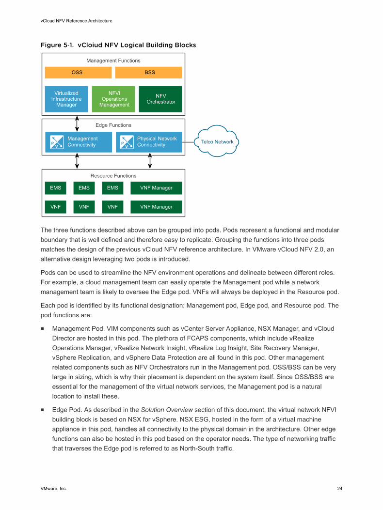
Figure 5‑1. vCloiud NFV Logical Building Blocks
VNF Manager
BSSOSS
Edge Functions
ManagementConnectivity
Physical NetworkConnectivity
VirtualizedInfrastructure
Manager
NFVIOperations
ManagementNFV
Orchestrator
Management Functions
Resource Functions
VNF VNFVNF
EMS EMSEMS
VNF Manager
Telco Network
The three functions described above can be grouped into pods. Pods represent a functional and modularboundary that is well defined and therefore easy to replicate. Grouping the functions into three podsmatches the design of the previous vCloud NFV reference architecture. In VMware vCloud NFV 2.0, analternative design leveraging two pods is introduced.
Pods can be used to streamline the NFV environment operations and delineate between different roles.For example, a cloud management team can easily operate the Management pod while a networkmanagement team is likely to oversee the Edge pod. VNFs will always be deployed in the Resource pod.
Each pod is identified by its functional designation: Management pod, Edge pod, and Resource pod. Thepod functions are:
n Management Pod. VIM components such as vCenter Server Appliance, NSX Manager, and vCloudDirector are hosted in this pod. The plethora of FCAPS components, which include vRealizeOperations Manager, vRealize Network Insight, vRealize Log Insight, Site Recovery Manager,vSphere Replication, and vSphere Data Protection are all found in this pod. Other managementrelated components such as NFV Orchestrators run in the Management pod. OSS/BSS can be verylarge in sizing, which is why their placement is dependent on the system itself. Since OSS/BSS areessential for the management of the virtual network services, the Management pod is a naturallocation to install these.
n Edge Pod. As described in the Solution Overview section of this document, the virtual network NFVIbuilding block is based on NSX for vSphere. NSX ESG, hosted in the form of a virtual machineappliance in this pod, handles all connectivity to the physical domain in the architecture. Other edgefunctions can also be hosted in this pod based on the operator needs. The type of networking trafficthat traverses the Edge pod is referred to as North-South traffic.
vCloud NFV Reference Architecture
VMware, Inc. 24
n Resource Pod. Virtual Network Functions (VNFs) and their managers (VNFM) are placed in theResource pod. The VNFs then form the virtual network service.
n Edge / Resource Pod. With this release, we introduce a new construct that combines the Edge podand Resource pod functionality into a single collapsed pod. The Edge / Resource pod hosts both theservice constructs (VNFs) and the networking components they need.
Using this collapsed pod function, two designs are possible: two-pod and three-pod. The two-pod designis described in detail in the Two-Pod Design Overview section of this document, while the three-poddesign is covered in the Three-Pod Design Overview section. Guidance is provided on the use cases bestfitting each of the designs in the Using Two-Pod or Three-Pod Design for vCloud NFV section of thedocument.
Service Life CycleThe service life cycle design principle focuses on ease, and the speed at which VNFs can be consumedby the NFV platform, maintained over their life time, and deployed when needed. The VIM facilitates thisapproach and enables the CSP to perform common tasks to benefit from virtualizing network functions.
VNF vendors package their VNFs and deliver them to the CSP in a consumable form. CSPs can thenquickly onboard a VNF to vCloud Director to speed up deployment, and to ensure that VNFs areconsistently behaving in a predictable fashion in each deployment.
Once the VNF is onboarded, it is placed in a catalog that can be consumed based on the CSP policies.The goal of placing a VNF in the vCloud Director catalog is to enable the NFVO, responsible for creatingthe service, to quickly and programmatically deploy the service components required to run the service.vCloud Director also addresses life cycle activities such as deployment, decommissioning, and restartingservice components
Since many operational activities around VNFs are performed using higher layer components such as theVNFM and VNFO, the vCloud NFV platform provides a well documented northbound API that can beused by these components to complete the service life cycle.
Tenant Based ArchitectureThe NFVI is shared between multiple entities, referred to as tenants of the NFVI. A fundamental aspect ofthe design is ensuring that multiple tenants remain logically isolated from each other, although thephysical and virtual layers they use may be shared.
The design principles for multitenancy are:
n An NFVI tenant cannot interfere with the operations of another tenant, nor can one VNF interfere withanother.
n Fair resource sharing must take place. When the system has available resources, and tenants requirethese resources, they are split appropriately among the tenants.
vCloud NFV Reference Architecture
VMware, Inc. 25
n One tenant network must be isolated from another. A tenant choice of IP allocation, default gateway,and routing, cannot interfere with another tenant. In fact, another tenant may use the samenetworking information. Network access from one tenant to another must follow the trustednetworking and security policy of the CSP
n A tenant must be proactively monitored to ensure health and efficiency to deliver optimal servicequality.
The design principles allow multiple tenants to share resources on the operator's network, and tomaintain a great deal of control and self-management. Tenants can use overlapping IP addressingand, together with the use of resource policies, the CSP can ensure that the amount of resourcesrequired by the tenant is controlled. The tenant based architecture together with a well-definedprocess for VNF onboarding and VNF resource allocation, means that a CSP can offer service-levelagreements (SLAs) with which high quality, mission critical services, can be created. With theintegrated operational management principles, SLAs can also be monitored and ensured.
Integrated Operational ManagementThe multilayer, multi-vendor nature of the NFV environment can lead to increase operationalmanagement complexity. To resolve this complexity, vCloud NFV is integrated with a robust operationalmanagement system that monitors and analyzes components involved in the NFV environment. Whenthe physical servers and switches include monitoring adaptors for the VMware operational managementcomponents, the entire system, including the virtualization layer and the VNF themselves, can beautomatically discovered, monitored, and analyzed.
Designing the monitoring system to provide visibility into the entire environment requires the ability tointegrate data collection from VMware software components alongside third-party elements such asVNFs, routers, switches, servers, and storage elements. This complete visibility is achieved using a suiteof software components described in the Operations Management Components section of this document.
The data collected is continuously analyzed, which allows for near real-time monitoring. This results inrobust performance monitoring that enables the operator to perform detailed capacity management. Sincethe monitoring system is tightly integrated with the VIM, virtualization, and physical layers, proactivefailure avoidance is implemented by leveraging vRealize Operations Manager analytics and DRS. Incases where a problem does occur root cause analysis can easily be performed, since the operator hasholistic visibility into the entire system.
Two-Pod Design OverviewBy leveraging the enhanced tenant capabilities of vCloud Director, VMware vCloud NFV 2.0 facilitatescombining the edge and resource functionality into a single, collapsed pod. In combination, a smallerfootprint design is possible. CSPs can use a two-pod design to gain operational experience with vCloudNFV. As demand grows, they scale up and scale out within the two-pod construct.
vCloud NFV Reference Architecture
VMware, Inc. 26
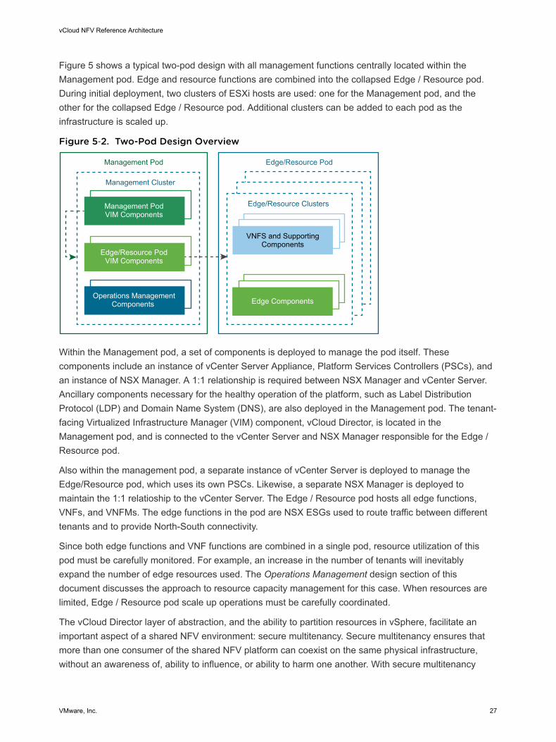
Figure 5 shows a typical two-pod design with all management functions centrally located within theManagement pod. Edge and resource functions are combined into the collapsed Edge / Resource pod.During initial deployment, two clusters of ESXi hosts are used: one for the Management pod, and theother for the collapsed Edge / Resource pod. Additional clusters can be added to each pod as theinfrastructure is scaled up.
Figure 5‑2. Two-Pod Design Overview
Operations ManagementComponents
Management PodVIM Components
Edge/Resource PodVIM Components
Management Pod Edge/Resource Pod
Edge Components
Edge/Resource Clusters
Management Cluster
VNFS and SupportingComponents
Within the Management pod, a set of components is deployed to manage the pod itself. Thesecomponents include an instance of vCenter Server Appliance, Platform Services Controllers (PSCs), andan instance of NSX Manager. A 1:1 relationship is required between NSX Manager and vCenter Server.Ancillary components necessary for the healthy operation of the platform, such as Label DistributionProtocol (LDP) and Domain Name System (DNS), are also deployed in the Management pod. The tenant-facing Virtualized Infrastructure Manager (VIM) component, vCloud Director, is located in theManagement pod, and is connected to the vCenter Server and NSX Manager responsible for the Edge /Resource pod.
Also within the management pod, a separate instance of vCenter Server is deployed to manage theEdge/Resource pod, which uses its own PSCs. Likewise, a separate NSX Manager is deployed tomaintain the 1:1 relatioship to the vCenter Server. The Edge / Resource pod hosts all edge functions,VNFs, and VNFMs. The edge functions in the pod are NSX ESGs used to route traffic between differenttenants and to provide North-South connectivity.
Since both edge functions and VNF functions are combined in a single pod, resource utilization of thispod must be carefully monitored. For example, an increase in the number of tenants will inevitablyexpand the number of edge resources used. The Operations Management design section of thisdocument discusses the approach to resource capacity management for this case. When resources arelimited, Edge / Resource pod scale up operations must be carefully coordinated.
The vCloud Director layer of abstraction, and the ability to partition resources in vSphere, facilitate animportant aspect of a shared NFV environment: secure multitenancy. Secure multitenancy ensures thatmore than one consumer of the shared NFV platform can coexist on the same physical infrastructure,without an awareness of, ability to influence, or ability to harm one another. With secure multitenancy
vCloud NFV Reference Architecture
VMware, Inc. 27
resources are over-subscribed, yet fairly shared and guaranteed as necessary. This is the bedrock of theNFV business case. Implementation of secure multitenancy is described in the Secure Multitenancysection of this document. Tenants using the two-pod based NFV environment are able to configure theirown virtual networking functionality and autonomously prepare VNFs for service usage.
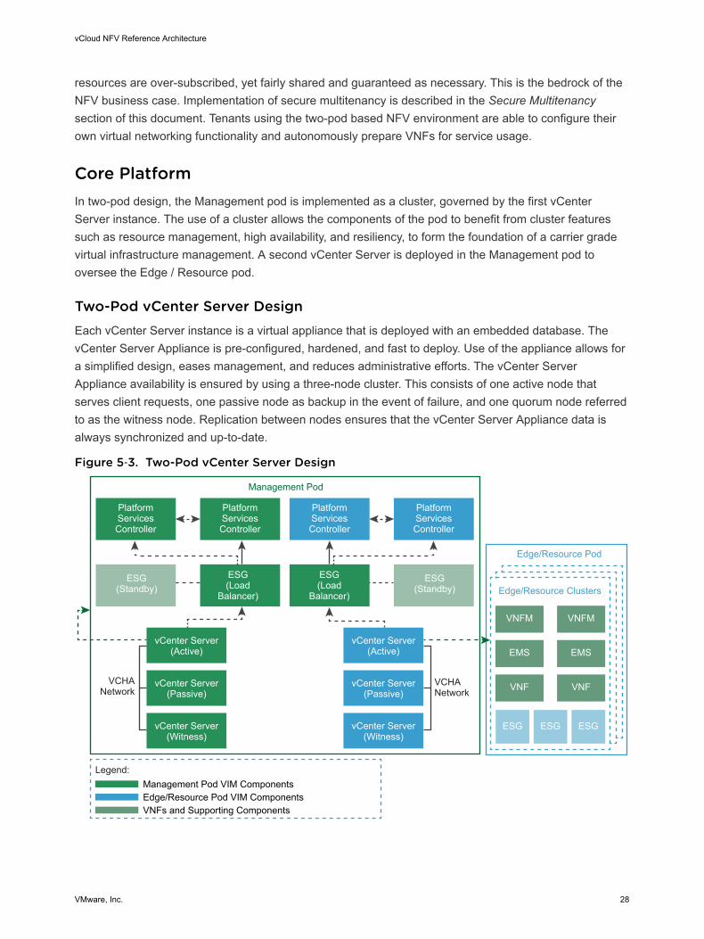
Core PlatformIn two-pod design, the Management pod is implemented as a cluster, governed by the first vCenterServer instance. The use of a cluster allows the components of the pod to benefit from cluster featuressuch as resource management, high availability, and resiliency, to form the foundation of a carrier gradevirtual infrastructure management. A second vCenter Server is deployed in the Management pod tooversee the Edge / Resource pod.
Two-Pod vCenter Server DesignEach vCenter Server instance is a virtual appliance that is deployed with an embedded database. ThevCenter Server Appliance is pre-configured, hardened, and fast to deploy. Use of the appliance allows fora simplified design, eases management, and reduces administrative efforts. The vCenter ServerAppliance availability is ensured by using a three-node cluster. This consists of one active node thatserves client requests, one passive node as backup in the event of failure, and one quorum node referredto as the witness node. Replication between nodes ensures that the vCenter Server Appliance data isalways synchronized and up-to-date.
Figure 5‑3. Two-Pod vCenter Server Design
PlatformServicesController
ESG(Standby)
ESG(Load
Balancer)
ESG(Load
Balancer)
ESG(Standby)
vCenter Server(Active)
vCenter Server(Passive)
vCenter Server(Witness)
VCHANetwork
VCHANetwork
VNFM VNFM
EMS EMS
VNF VNF
Edge/Resource Pod
Edge/Resource Clusters
ESG ESGESG
PlatformServicesController
PlatformServicesController
PlatformServicesController
vCenter Server(Active)
vCenter Server(Passive)
vCenter Server(Witness)
Legend:
Edge/Resource Pod VIM ComponentsManagement Pod VIM Components
VNFs and Supporting Components
Management Pod
vCloud NFV Reference Architecture
VMware, Inc. 28
The Platform Services Controller contains common infrastructure security services such as VMwarevCenter® Single Sign-On, VMware Certificate Authority, licensing, and server reservation and certificatemanagement services. The Platform Services Controller handles identity management for administratorsand applications that interact with the vSphere platform. Each pair of Platform Services Controllers isconfigured to use a separate vCenter Single Sign On domain. This approach secures the managementcomponents by maintaining administrative separation between the two pods. Platform ServicesControllers are deployed as load balanced appliances external to vCenter Server for high availability. AnNSX ESG instance is used as the load balancer between the Platform Services Controllers and theirrespective vCenter Server instances.
Each vCenter Server instance and its Platform Services Controller data retention is ensured by using thenative backup service that is built into the appliances. This backup is performed to a separate storagesystem using network protocols such as SFTP, HTTPS, and SCP.
Local storage drives on the ESXi hosts are pooled into a highly available shared vSAN datastore foroptimum utilization of storage capacity. Each cluster has its own vSAN datastore, an abstractedrepresentation of the storage into which virtual machine persistent data is stored. All managementcomponents are stored in the management cluster datastore, while VNF workloads deployed from vCloudDirector are stored in the resource cluster datastore. This allows for the separation of administrative,performance, and failure storage boundaries for management and VNF workloads
Two-Pod Virtual Networking Design with VMware NSX ManagerEach NSX Manager has a 1:1 relationship with vCenter Server. Therefore, two NSX Managers arecreated in the management cluster. Figure 7 shows how the NSX Manager is used in a two-pod design.
vCloud NFV Reference Architecture
VMware, Inc. 29
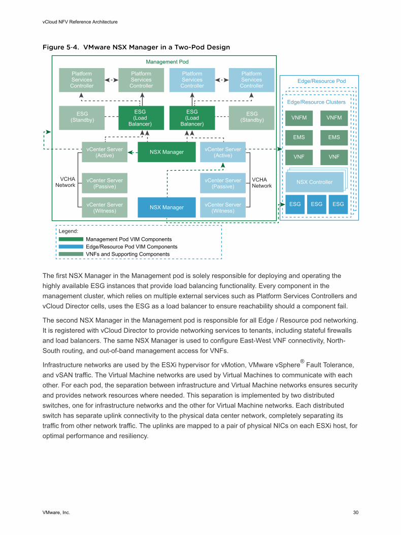
Figure 5‑4. VMware NSX Manager in a Two-Pod Design
PlatformServicesController
ESG(Standby)
ESG(Load
Balancer)
ESG(Load
Balancer)
ESG(Standby)
vCenter Server(Active)
vCenter Server(Passive)
vCenter Server(Witness)
VCHANetwork
VCHANetwork
VNFM VNFM
EMS EMS
VNF VNF
Edge/Resource Pod
Edge/Resource Clusters
ESG ESGESG
PlatformServicesController
PlatformServicesController
PlatformServicesController
vCenter Server(Active)
vCenter Server(Passive)
vCenter Server(Witness)
Legend:
Edge/Resource Pod VIM ComponentsManagement Pod VIM Components
VNFs and Supporting Components
Management Pod
NSX Manager
NSX Manager
NSX Controller
The first NSX Manager in the Management pod is solely responsible for deploying and operating thehighly available ESG instances that provide load balancing functionality. Every component in themanagement cluster, which relies on multiple external services such as Platform Services Controllers andvCloud Director cells, uses the ESG as a load balancer to ensure reachability should a component fail.
The second NSX Manager in the Management pod is responsible for all Edge / Resource pod networking.It is registered with vCloud Director to provide networking services to tenants, including stateful firewallsand load balancers. The same NSX Manager is used to configure East-West VNF connectivity, North-South routing, and out-of-band management access for VNFs.
Infrastructure networks are used by the ESXi hypervisor for vMotion, VMware vSphere® Fault Tolerance,and vSAN traffic. The Virtual Machine networks are used by Virtual Machines to communicate with eachother. For each pod, the separation between infrastructure and Virtual Machine networks ensures securityand provides network resources where needed. This separation is implemented by two distributedswitches, one for infrastructure networks and the other for Virtual Machine networks. Each distributedswitch has separate uplink connectivity to the physical data center network, completely separating itstraffic from other network traffic. The uplinks are mapped to a pair of physical NICs on each ESXi host, foroptimal performance and resiliency.
vCloud NFV Reference Architecture
VMware, Inc. 30
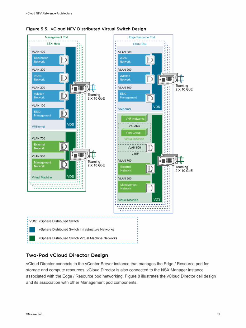
Figure 5‑5. vCloud NFV Distributed Virtual Switch Design
VNF Networks
Port Group
Virtual machine
ESXi Host
Edge/Resource Pod
VХLANs
VLAN 600
ManagementNetwork
VLAN 500
VLAN 700
VLAN 100
VLAN 200
VLAN 300
VLAN 400
ExternalNetwork
ESXiManagement
vMotionNetwork
vSANNetwork
ReplicationNetwork
VDS
VDS
VDS
ESXi Host
Management Pod
Teaming 2 X 10 GbE
VTEP
VMKernel
VMKernel
Virtual Machine
ManagementNetwork
VLAN 500
VLAN 700
ExternalNetwork
VDSVirtual Machine
VLAN 100
VLAN 200
VLAN 300
ESXiManagement
vMotionNetwork
vSANNetwork
vSphere Distributed Switch Infrastructure Networks
VDS: vSphere Distributed Switch
vSphere Distributed Switch Virtual Machine Networks
Teaming 2 X 10 GbE
Teaming 2 X 10 GbE
Teaming 2 X 10 GbE
Two-Pod vCloud Director DesignvCloud Director connects to the vCenter Server instance that manages the Edge / Resource pod forstorage and compute resources. vCloud Director is also connected to the NSX Manager instanceassociated with the Edge / Resource pod networking. Figure 8 illustrates the vCloud Director cell designand its association with other Management pod components.
vCloud NFV Reference Architecture
VMware, Inc. 31
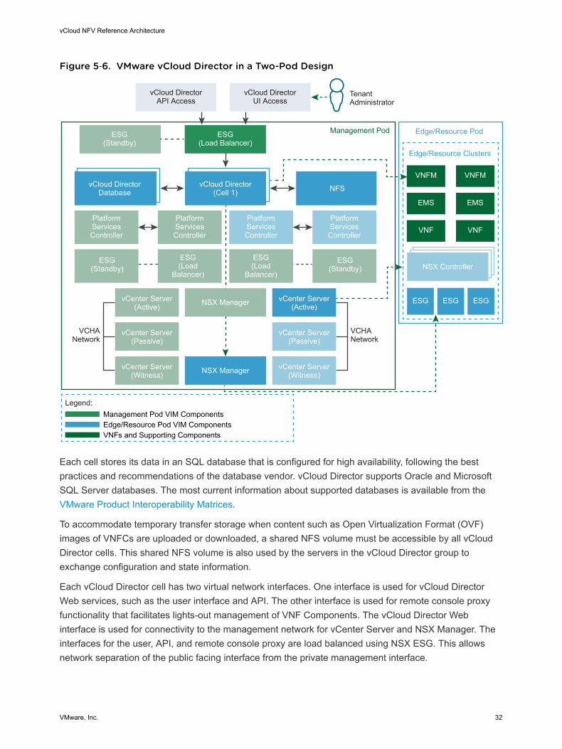
Figure 5‑6. VMware vCloud Director in a Two-Pod Design
ESG(Standby)
PlatformServicesController
ESG(Load Balancer)
vCloud DirectorAPI Access
vCloud DirectorUI Access
TenantAdministrator
ESG(Standby)
ESG(Load
Balancer)
ESG(Load
Balancer)
ESG(Standby)
vCloud DirectorDatabase
vCloud Director(Cell 1) NFS
NSX ManagervCenter Server(Active)
vCenter Server(Passive)
vCenter Server(Witness) NSX Manager
VCHANetwork
VCHANetwork
VNFM VNFM
EMS EMS
VNF VNF
Edge/Resource Pod
Edge/Resource Clusters
NSX Controller
ESG ESGESG
PlatformServicesController
PlatformServicesController
PlatformServicesController
vCenter Server(Active)
vCenter Server(Passive)
vCenter Server(Witness)
Legend:
Edge/Resource Pod VIM ComponentsManagement Pod VIM Components
VNFs and Supporting Components
Management Pod
Each cell stores its data in an SQL database that is configured for high availability, following the bestpractices and recommendations of the database vendor. vCloud Director supports Oracle and MicrosoftSQL Server databases. The most current information about supported databases is available from the VMware Product Interoperability Matrices.
To accommodate temporary transfer storage when content such as Open Virtualization Format (OVF)images of VNFCs are uploaded or downloaded, a shared NFS volume must be accessible by all vCloudDirector cells. This shared NFS volume is also used by the servers in the vCloud Director group toexchange configuration and state information.
Each vCloud Director cell has two virtual network interfaces. One interface is used for vCloud DirectorWeb services, such as the user interface and API. The other interface is used for remote console proxyfunctionality that facilitates lights-out management of VNF Components. The vCloud Director Webinterface is used for connectivity to the management network for vCenter Server and NSX Manager. Theinterfaces for the user, API, and remote console proxy are load balanced using NSX ESG. This allowsnetwork separation of the public facing interface from the private management interface.
vCloud NFV Reference Architecture
VMware, Inc. 32
The vCloud Director integration with vCenter Server allows vCloud Director to manage the pooling ofresources, their allocation, and reservation. vCloud Director abstracts the vCenter Server resourcemanagement constructs and provides its own view for tenant resource management. CSPs can selectone of three allocation models allowing them to assign resources to tenants. This gives CSPs theflexibility to manage the resource of individual OvDCs, depending on the workload resource requirementsof that OvDC. These allocation models are briefly described in the KB article Allocation Models forOrganizations using vCloud Director.
vCloud Director is closely integrated with NSX for vSphere, which provides tenants with more featuresand capabilities for managing their VNF networking needs directly from within the vCloud Director Webinterface. With VMware vCloud NFV 2.0 all the building blocks for creating secure multitenant VNFnetworks are in the hands of the tenant. These network services include firewall, network addresstranslation (NAT), static and dynamic routing, load balancing, and Virtual Private Networks (VPNs).Tenants can provision VXLAN backed logical switches for East-West VNF component connectivity. At thesame time, they can deploy NSX ESGs for North-South traffic, as required when connecting to othertenants or to external networks. With this integration, CSPs spend fewer administrative resourcesconfiguring and setting up VNFs, reducing the cost of managing the platform.
Secure MultitenancyTogether, the vCenter Server, NSX Manager, and vCloud Director form the secure multitenant platform ofthe vCloud NFV design. vCenter Server provides the infrastructure for fine grained allocation andpartitioning of compute and storage resources, while NSX for vSphere creates the network virtualizationlayer. The network virtualization layer is an abstraction between physical and virtual networks. NSX forvSphere provides logical switches, firewalls, load balancers, and VPNs.
vCloud Director provides an additional abstraction layer, dividing pooled resources among tenants. Thissection describes how the vCloud Director abstraction layers, PvDC and OvDC, are leveraged to providea secure multitenant environment to deploy and run VNFs.
vCloud NFV Reference Architecture
VMware, Inc. 33
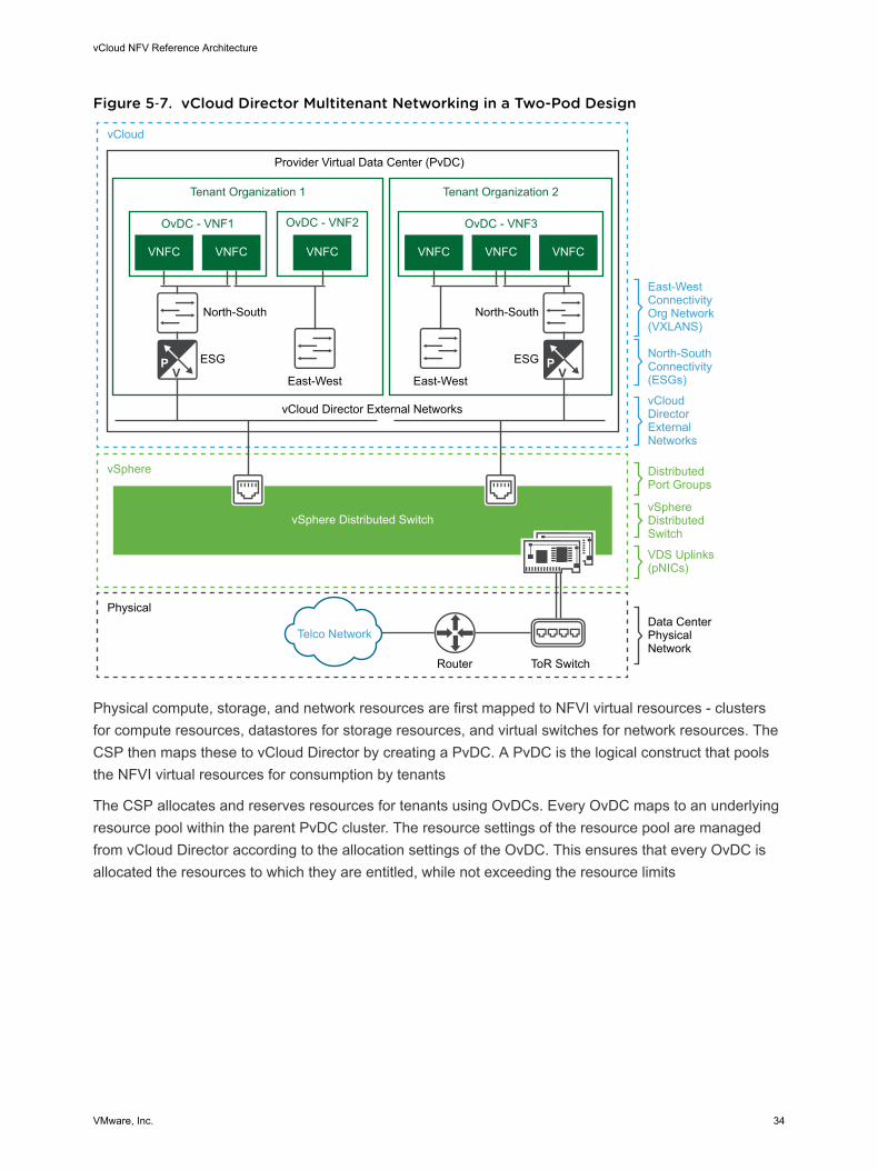
Figure 5‑7. vCloud Director Multitenant Networking in a Two-Pod Design
Tenant Organization 1
vCloud Director External Networks
vSphere Distributed Switch
Provider Virtual Data Center (PvDC)
vCloud
vSphere
Physical
Telco Network
Router ToR Switch
North-South
East-West East-West
ESG
North-South
ESG
OvDC - VNF1
VNFC VNFC VNFC
OvDC - VNF2
Tenant Organization 2
DistributedPort Groups
vSphereDistributedSwitch
VDS Uplinks(pNICs)
Data CenterPhysical Network
OvDC - VNF3
VNFC VNFC VNFC
East-WestConnectivityOrg Network(VXLANS)
North-SouthConnectivity(ESGs)
vCloud DirectorExternal Networks
Physical compute, storage, and network resources are first mapped to NFVI virtual resources - clustersfor compute resources, datastores for storage resources, and virtual switches for network resources. TheCSP then maps these to vCloud Director by creating a PvDC. A PvDC is the logical construct that poolsthe NFVI virtual resources for consumption by tenants
The CSP allocates and reserves resources for tenants using OvDCs. Every OvDC maps to an underlyingresource pool within the parent PvDC cluster. The resource settings of the resource pool are managedfrom vCloud Director according to the allocation settings of the OvDC. This ensures that every OvDC isallocated the resources to which they are entitled, while not exceeding the resource limits
vCloud NFV Reference Architecture
VMware, Inc. 34
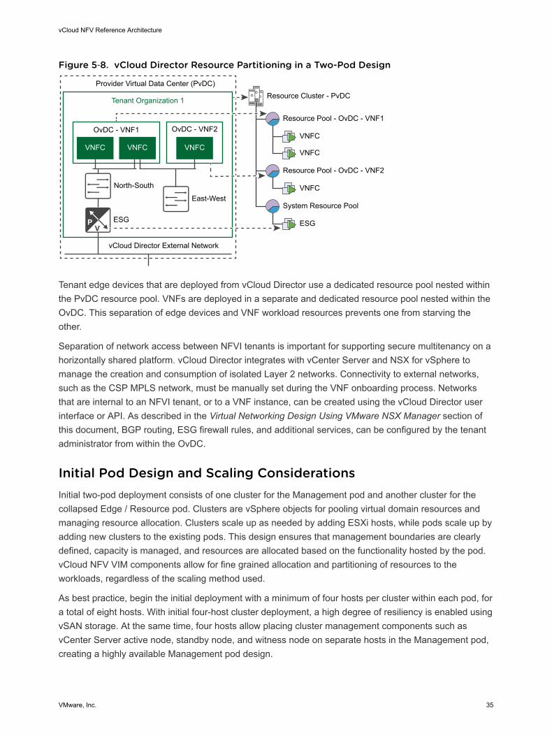
Figure 5‑8. vCloud Director Resource Partitioning in a Two-Pod Design
Tenant Organization 1 Resource Cluster - PvDC
VNFC
VNFC
VNFC
ESG
Resource Pool - OvDC - VNF1
Resource Pool - OvDC - VNF2
System Resource Pool
vCloud Director External Network
Provider Virtual Data Center (PvDC)
North-South
East-West
ESG
OvDC - VNF1
VNFC VNFC VNFC
OvDC - VNF2
Tenant edge devices that are deployed from vCloud Director use a dedicated resource pool nested withinthe PvDC resource pool. VNFs are deployed in a separate and dedicated resource pool nested within theOvDC. This separation of edge devices and VNF workload resources prevents one from starving theother.
Separation of network access between NFVI tenants is important for supporting secure multitenancy on ahorizontally shared platform. vCloud Director integrates with vCenter Server and NSX for vSphere tomanage the creation and consumption of isolated Layer 2 networks. Connectivity to external networks,such as the CSP MPLS network, must be manually set during the VNF onboarding process. Networksthat are internal to an NFVI tenant, or to a VNF instance, can be created using the vCloud Director userinterface or API. As described in the Virtual Networking Design Using VMware NSX Manager section ofthis document, BGP routing, ESG firewall rules, and additional services, can be configured by the tenantadministrator from within the OvDC.
Initial Pod Design and Scaling ConsiderationsInitial two-pod deployment consists of one cluster for the Management pod and another cluster for thecollapsed Edge / Resource pod. Clusters are vSphere objects for pooling virtual domain resources andmanaging resource allocation. Clusters scale up as needed by adding ESXi hosts, while pods scale up byadding new clusters to the existing pods. This design ensures that management boundaries are clearlydefined, capacity is managed, and resources are allocated based on the functionality hosted by the pod.vCloud NFV VIM components allow for fine grained allocation and partitioning of resources to theworkloads, regardless of the scaling method used.
As best practice, begin the initial deployment with a minimum of four hosts per cluster within each pod, fora total of eight hosts. With initial four-host cluster deployment, a high degree of resiliency is enabled usingvSAN storage. At the same time, four hosts allow placing cluster management components such asvCenter Server active node, standby node, and witness node on separate hosts in the Management pod,creating a highly available Management pod design.
vCloud NFV Reference Architecture
VMware, Inc. 35
The initial number and sizing of management components in the Management pod are pre-planned. As aresult, the capacity requirement of the Management pod is expected to remain steady. Considerationswhen planning Management pod storage capacity must include operational headroom for VNF files,snapshots, backups, virtual machine templates, operating system images, and log files.
The collapsed edge / resource cluster sizing will change based on the VNF and networking requirements.When planning for the capacity of the Edge / Resource pod, tenants must work with the VNF vendors togather requirements for the VNF service to be deployed. Such information is typically available from theVNF vendors in the form of deployment guides and sizing guidelines. These guidelines are directlyrelated to the scale of the VNF service, for example to the number of subscribers to be supported. Inaddition, the capacity utilization of ESGs must be taken into consideration, especially when moreinstances of ESGs are deployed to scale up as the number of VNFs increases.
When scaling up the Edge / Resource pod by adding hosts to the cluster, newly added resources areautomatically pooled, resulting in added capacity to the PvDC. New tenants can be provisioned toconsume resources from the total available pooled capacity. Allocation settings for existing tenants mustbe modified before they can benefit from increased resource availability. Tenant administrators can thenfine tune the resource allocation of their OvDCs and allocate resources to the VNF workloads.
New clusters are added to a PvDC to scale out the Edge / Resource pod. The CSP can migrate existingVNF workloads from the initial cluster to the newly added cluster to ensure ESG capacity availability. Dueto leaf-and-spine network design, additional ESGs in the new cluster will continue to be deployed in theinitial cluster.
Refer to the vSphere 6.5 Configuration Maximums document and the VMware vCloud DirectorConfiguration Maximums paper for more information.
VNF OnboardingA VNF is onboarded to a two-pod vCloud NFV design by following these steps: preparing the VNF forconsumption by vCloud Director, importing the VNF images, ensuring that the VNF is setup correctly inthe environment, storing it in a vCloud Director catalog, and deploying it by various means. The processcan be divided into CSP operations and tenant operations, as detailed in this section of the document.
vCloud Director supports importing VNFs as standard OVF/OVA packages. While multiple options areavailable to create an OVF/OVA package, for best practices the VNF vendor must author the package ina separate environment identical to the target vCloud NFV, to match its features and capabilities. Toimport a VNF as a standard OVF package, follow these steps:
1 Create a vApp and add the VNFCs to it. Use of preconfigured, reusable virtual machine VNFCtemplates simplifies the process of vApp creation.
2 East-West vApp VNF networks are created by provisioning organization networks. North-Southconnectivity requires routed organization networks. Both networks are configured from within vCloudDirector.
3 VNF Components are connected to the networks and the VNF is validated on the NFVI platform
vCloud NFV Reference Architecture
VMware, Inc. 36
4 The final vApp is captured as a vApp template and exported as an OVF package provided to theCSP.
Ensuring that the resources needed for the VNF are available is not only integral, but central to theplatform design. This process is typically collaborative between the VNF vendor and the CSP. The VNFvendor provides guidance based on lab testing, regarding the amount of virtual resources needed tosupport a specific size or scale of telecommunications service. For example, a virtual Evolved PacketCore (vEPC) is likely to specify that to serve a certain number of subscribers with active features such asdeep packet inspection (DPI) and quality of service (QoS), a specific number of vCPUs, memory, networkbandwidth, and storage is required. The NFVI operator accounts for near-future scale requirements, usingthe mechanisms described in this section to make resources available.
Before a VNF is onboarded, the CSP must collect prerequisite information from the VNF supplier. Thisincludes configuration information such as the number of networks required, IP ranges, and North-Southnetwork connectivity.
vCloud Director uses the concept of catalogs for storing content. Catalogs are containers for VNFtemplates and media images. CSPs can create global catalogs with master VNF templates that can beshared to one or more tenants, while tenants retain their own private catalog of VNF templates. TheOVF/OVA package of a VNF is directly imported into the tenant catalog. In addition to VNF templates, thecatalog may contain VNF Component templates, used to scale deployed VNFs.
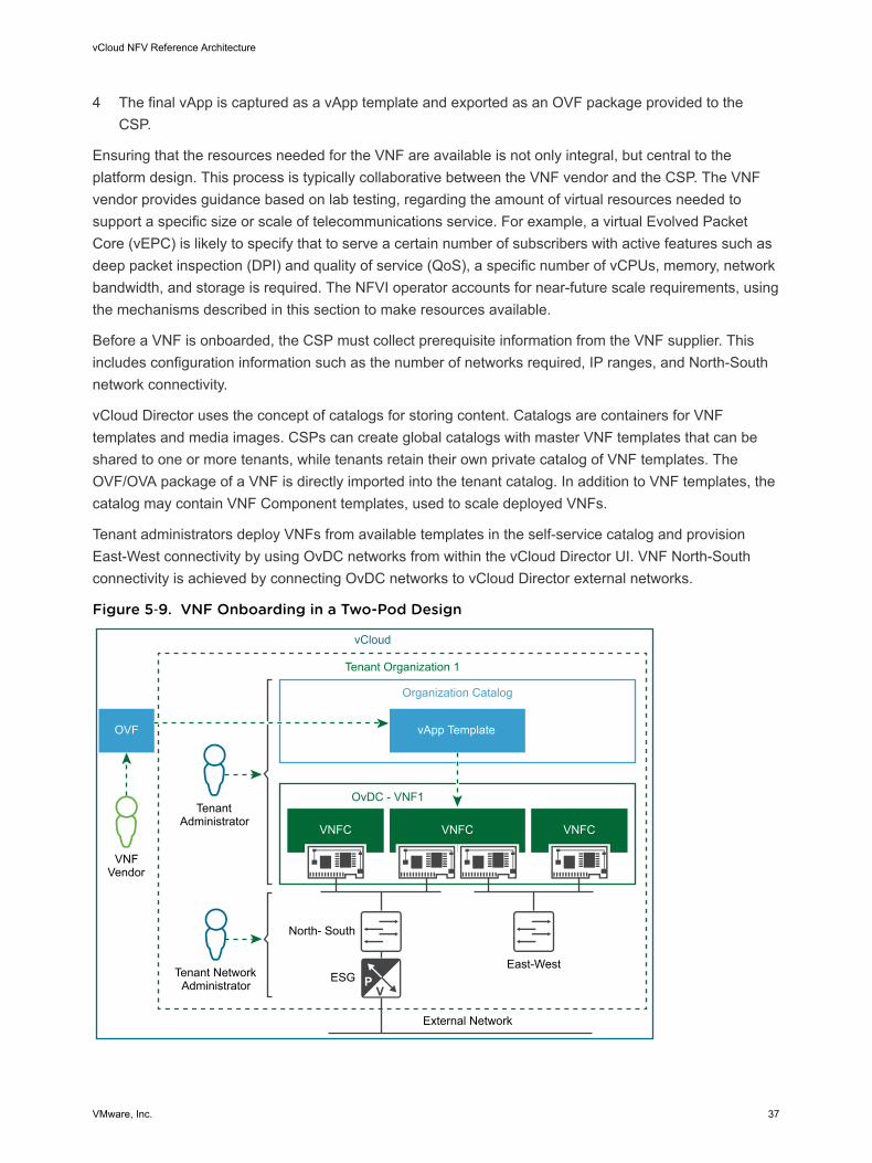
Tenant administrators deploy VNFs from available templates in the self-service catalog and provisionEast-West connectivity by using OvDC networks from within the vCloud Director UI. VNF North-Southconnectivity is achieved by connecting OvDC networks to vCloud Director external networks.
Figure 5‑9. VNF Onboarding in a Two-Pod Design
Tenant Administrator
Tenant Network Administrator
Tenant Organization 1
vCloud
External Network
North- South
East-WestESG
OvDC - VNF1
Organization Catalog
VNFC
OVF
VNFC
vApp Template
VNFC
VNFVendor
vCloud NFV Reference Architecture
VMware, Inc. 37
vCloud Director exposes a rich set of REST API calls to allow automation. Using these API calls, theupstream VNFM and NFVO can automate all aspects of the VNF lifecycle. Examples include VNFdeployment from a catalog, tenant network creation and configuration, power operations, and VNFdecommissioning. The complete list of APIs are described in detail in the vCloud API Programming Guidefor Service Providers document.
in the file. These configuration parameters are interpreted by the system when the VNFC is deployed andcan be used to specify advanced performance tuning parameters such as those for NUMA node affinity,interrupt coalescing, and latency sensitivity. These are further described in the Performance section ofthis document.
While some VNFs may have their own application level high availability capabilities, all VNFs canleverage the vSphere platform high availability features such as vSphere Fault Tolerance, vSphere HA,and Orchestrated HA. vSphere Fault Tolerance provides continuous availability for virtual machines (VMs)by creating and maintaining a Secondary VM that is identical to, and continuously available to replace,the Primary VM in the event of a failover. vSphere HA protects VMs from host failure by restarting the VMon another host in the cluster. Orchestrated HA is an extension to vSphere HA that allows the VNFvendor or CSP to specify rules for VM startup, based on application dependencies during a vSphere HArestart. These features all minimize administrative intervention and ensure operational efficiency for theNFVI platform and VNF workloads.
Three-Pod Design OverviewThe three-pod design completely separates the functional blocks by using a Management pod, an Edgepod, and a Resource pod, each for their respective functions. The initial deployment of a three-pod designrequires additional hardware when compared with a two-pod design, however each pod can scale upindependently of the others. Regardless of the pod design used to create the NFVI, VNFs will perform inthe same way.
Figure 5‑10. Three-Pod Design Overview
Operations ManagementComponents
Management PodVIM Components
Edge/Resource PodVIM Components
Management Pod
Cumpute Clusters
Edge Components
Edge Clusters
Management Cluster
VNFS and SupportingComponents
Resource Pod
Edge Pod
vCloud NFV Reference Architecture
VMware, Inc. 38
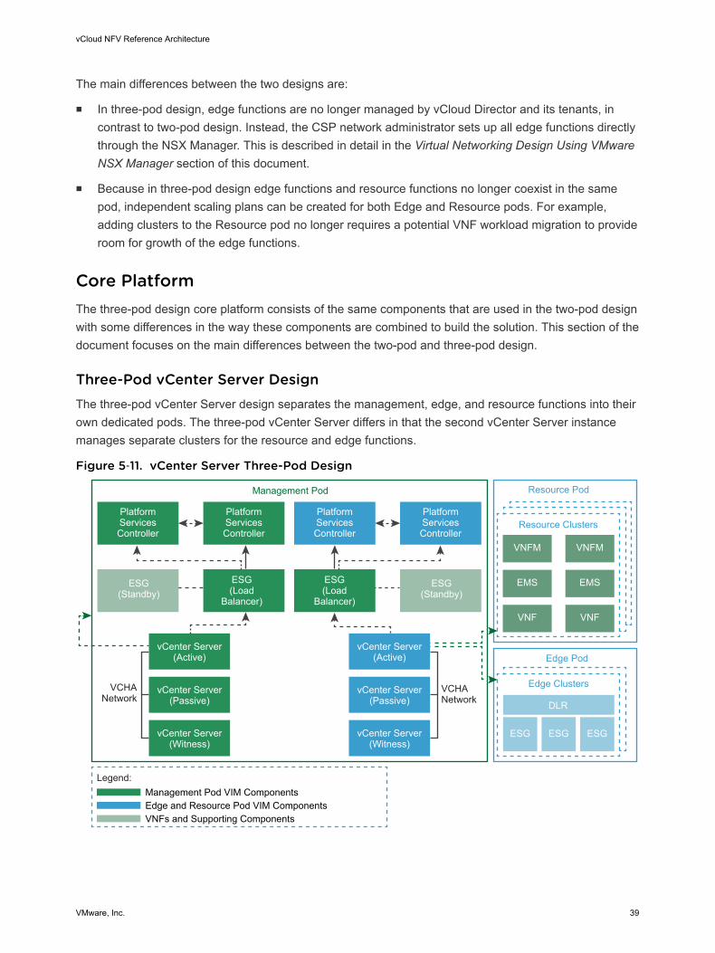
The main differences between the two designs are:
n In three-pod design, edge functions are no longer managed by vCloud Director and its tenants, incontrast to two-pod design. Instead, the CSP network administrator sets up all edge functions directlythrough the NSX Manager. This is described in detail in the Virtual Networking Design Using VMwareNSX Manager section of this document.
n Because in three-pod design edge functions and resource functions no longer coexist in the samepod, independent scaling plans can be created for both Edge and Resource pods. For example,adding clusters to the Resource pod no longer requires a potential VNF workload migration to provideroom for growth of the edge functions.
Core PlatformThe three-pod design core platform consists of the same components that are used in the two-pod designwith some differences in the way these components are combined to build the solution. This section of thedocument focuses on the main differences between the two-pod and three-pod design.
Three-Pod vCenter Server DesignThe three-pod vCenter Server design separates the management, edge, and resource functions into theirown dedicated pods. The three-pod vCenter Server differs in that the second vCenter Server instancemanages separate clusters for the resource and edge functions.
Figure 5‑11. vCenter Server Three-Pod Design
PlatformServicesController
ESG(Standby)
ESG(Load
Balancer)
ESG(Load
Balancer)
ESG(Standby)
vCenter Server(Active)
vCenter Server(Passive)
vCenter Server(Witness)
VCHANetwork
VCHANetwork
PlatformServicesController
PlatformServicesController
PlatformServicesController
vCenter Server(Active)
vCenter Server(Passive)
vCenter Server(Witness)
Legend:
Edge and Resource Pod VIM ComponentsManagement Pod VIM Components
VNFs and Supporting Components
Management Pod
VNFM VNFM
EMS EMS
VNF VNF
ESG ESGESG
Edge Pod
Edge Clusters
DLR
Resource Pod
Resource Clusters
vCloud NFV Reference Architecture
VMware, Inc. 39
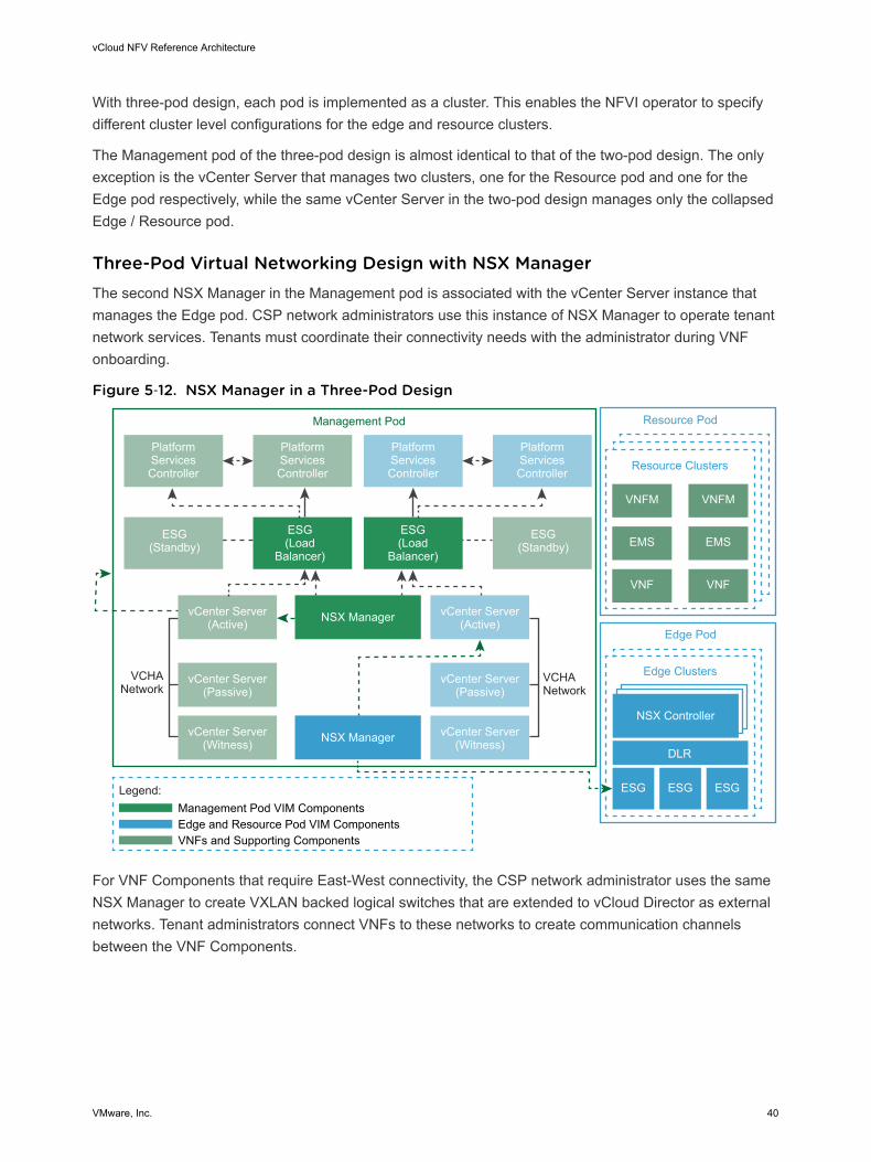
With three-pod design, each pod is implemented as a cluster. This enables the NFVI operator to specifydifferent cluster level configurations for the edge and resource clusters.
The Management pod of the three-pod design is almost identical to that of the two-pod design. The onlyexception is the vCenter Server that manages two clusters, one for the Resource pod and one for theEdge pod respectively, while the same vCenter Server in the two-pod design manages only the collapsedEdge / Resource pod.
Three-Pod Virtual Networking Design with NSX ManagerThe second NSX Manager in the Management pod is associated with the vCenter Server instance thatmanages the Edge pod. CSP network administrators use this instance of NSX Manager to operate tenantnetwork services. Tenants must coordinate their connectivity needs with the administrator during VNFonboarding.
Figure 5‑12. NSX Manager in a Three-Pod Design
PlatformServicesController
ESG(Standby)
ESG(Load
Balancer)
ESG(Load
Balancer)
ESG(Standby)
vCenter Server(Active)
vCenter Server(Passive)
vCenter Server(Witness)
VCHANetwork
VCHANetwork
PlatformServicesController
PlatformServicesController
PlatformServicesController
vCenter Server(Active)
vCenter Server(Passive)
vCenter Server(Witness)
Legend:
Edge and Resource Pod VIM ComponentsManagement Pod VIM Components
VNFs and Supporting Components
Management Pod
NSX Manager
NSX Manager
VNFM VNFM
EMS EMS
VNF VNF
Resource Pod
Resource Clusters
NSX Controller
ESG ESGESG
Edge Pod
Edge Clusters
DLR
For VNF Components that require East-West connectivity, the CSP network administrator uses the sameNSX Manager to create VXLAN backed logical switches that are extended to vCloud Director as externalnetworks. Tenant administrators connect VNFs to these networks to create communication channelsbetween the VNF Components.
vCloud NFV Reference Architecture
VMware, Inc. 40
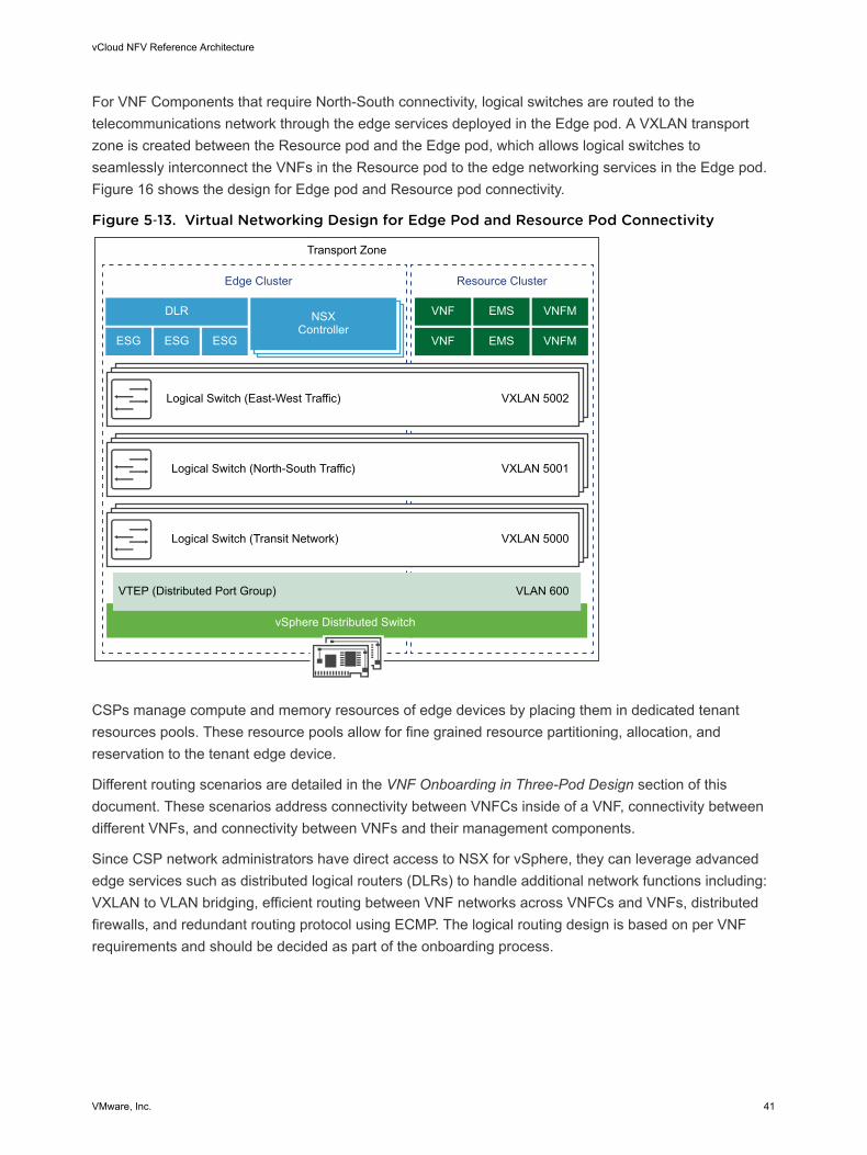
For VNF Components that require North-South connectivity, logical switches are routed to thetelecommunications network through the edge services deployed in the Edge pod. A VXLAN transportzone is created between the Resource pod and the Edge pod, which allows logical switches toseamlessly interconnect the VNFs in the Resource pod to the edge networking services in the Edge pod.Figure 16 shows the design for Edge pod and Resource pod connectivity.
Figure 5‑13. Virtual Networking Design for Edge Pod and Resource Pod Connectivity
Transport Zone
Logical Switch (East-West Traffic)
Logical Switch (North-South Traffic)
Logical Switch (Transit Network)
VTEP (Distributed Port Group)
VXLAN 5002
VXLAN 5001
VXLAN 5000
VLAN 600
vSphere Distributed Switch
Edge Cluster
DLR NSXController
ESG
VNF EMS VNFM
VNF EMS VNFMESG ESG
Resource Cluster
CSPs manage compute and memory resources of edge devices by placing them in dedicated tenantresources pools. These resource pools allow for fine grained resource partitioning, allocation, andreservation to the tenant edge device.
Different routing scenarios are detailed in the VNF Onboarding in Three-Pod Design section of thisdocument. These scenarios address connectivity between VNFCs inside of a VNF, connectivity betweendifferent VNFs, and connectivity between VNFs and their management components.
Since CSP network administrators have direct access to NSX for vSphere, they can leverage advancededge services such as distributed logical routers (DLRs) to handle additional network functions including:VXLAN to VLAN bridging, efficient routing between VNF networks across VNFCs and VNFs, distributedfirewalls, and redundant routing protocol using ECMP. The logical routing design is based on per VNFrequirements and should be decided as part of the onboarding process.
vCloud NFV Reference Architecture
VMware, Inc. 41
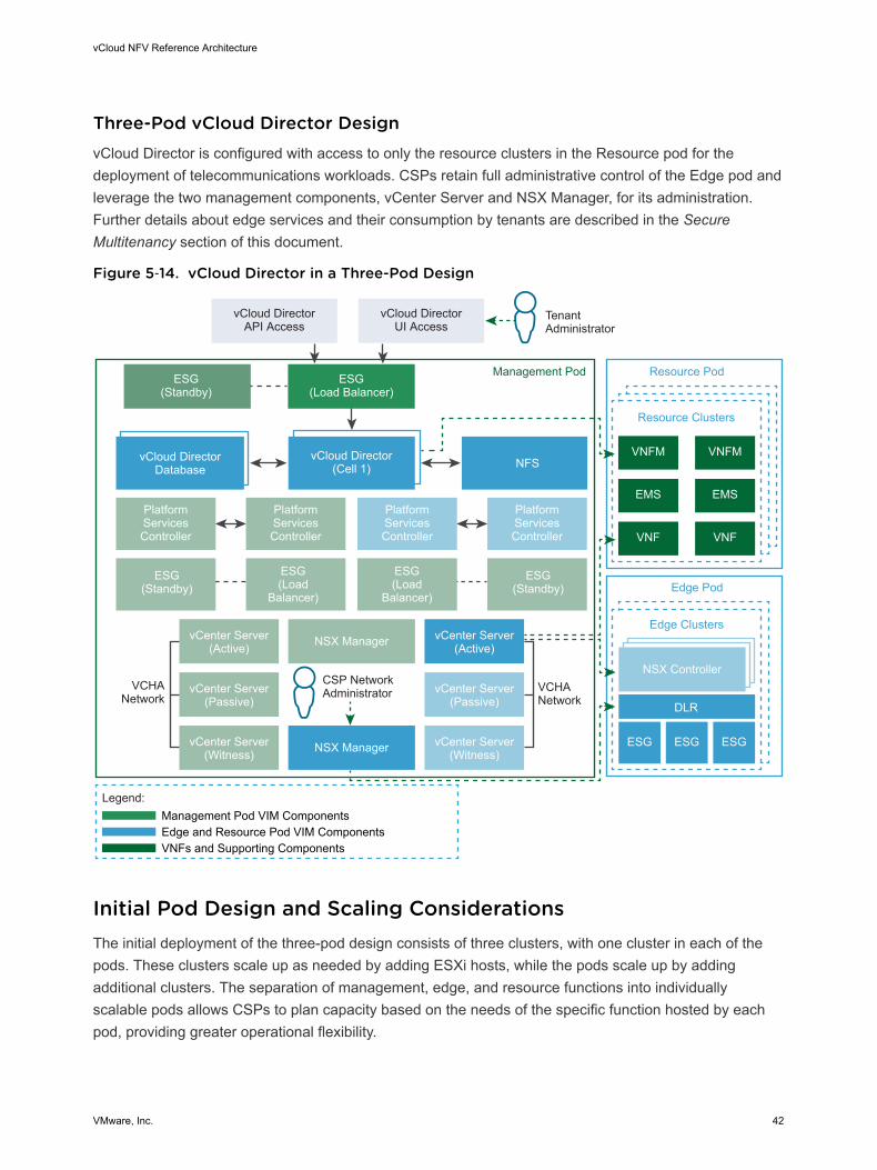
Three-Pod vCloud Director DesignvCloud Director is configured with access to only the resource clusters in the Resource pod for thedeployment of telecommunications workloads. CSPs retain full administrative control of the Edge pod andleverage the two management components, vCenter Server and NSX Manager, for its administration.Further details about edge services and their consumption by tenants are described in the SecureMultitenancy section of this document.
Figure 5‑14. vCloud Director in a Three-Pod Design
ESG(Standby)
PlatformServicesController
ESG(Load Balancer)
vCloud DirectorAPI Access
vCloud DirectorUI Access
TenantAdministrator
ESG(Standby)
ESG(Load
Balancer)
ESG(Load
Balancer)
ESG(Standby)
vCloud Director(Cell 1)
NSX ManagervCenter Server(Active)
vCenter Server(Passive)
vCenter Server(Witness) NSX Manager
VCHANetwork
VCHANetwork
VNFM VNFM
EMS EMS
VNF VNF
Resource Pod
Resource Clusters
NSX Controller
ESG ESGESG
Legend:
Edge and Resource Pod VIM ComponentsManagement Pod VIM Components
VNFs and Supporting Components
PlatformServicesController
PlatformServicesController
PlatformServicesController
vCenter Server(Active)
vCenter Server(Passive)
vCenter Server(Witness)
Edge Pod
Edge Clusters
DLR
CSP NetworkAdministrator
Management Pod
vCloud DirectorDatabase NFS
Initial Pod Design and Scaling ConsiderationsThe initial deployment of the three-pod design consists of three clusters, with one cluster in each of thepods. These clusters scale up as needed by adding ESXi hosts, while the pods scale up by addingadditional clusters. The separation of management, edge, and resource functions into individuallyscalable pods allows CSPs to plan capacity based on the needs of the specific function hosted by eachpod, providing greater operational flexibility.
vCloud NFV Reference Architecture
VMware, Inc. 42
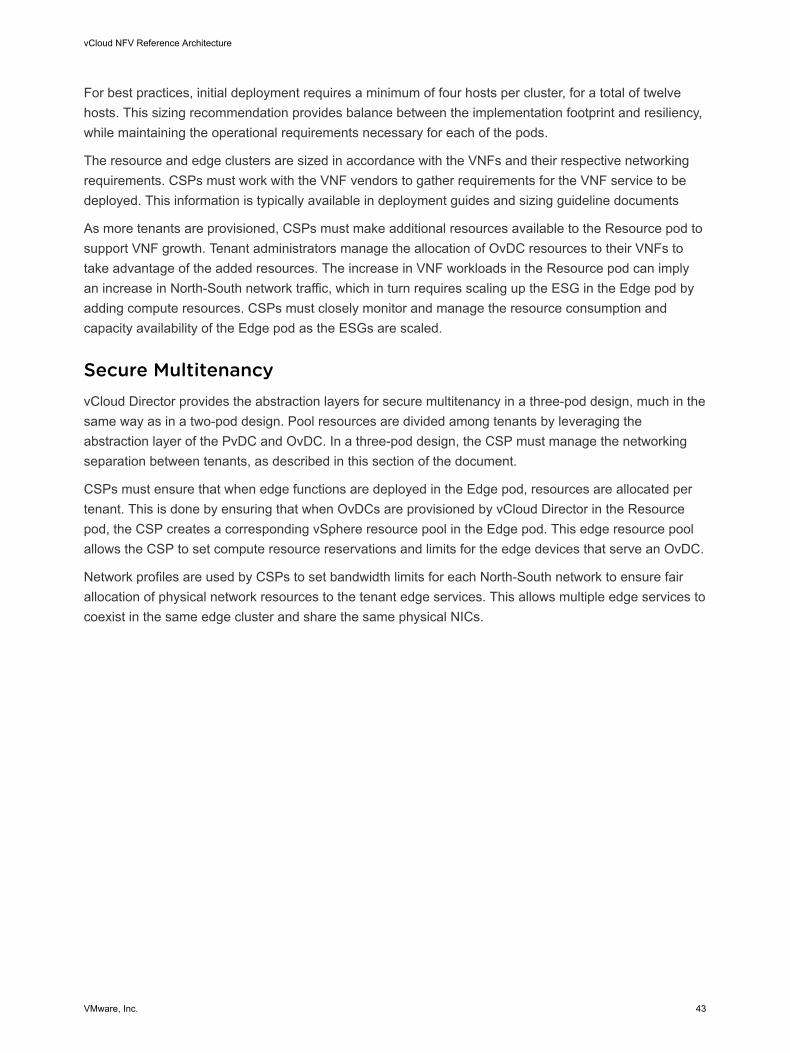
For best practices, initial deployment requires a minimum of four hosts per cluster, for a total of twelvehosts. This sizing recommendation provides balance between the implementation footprint and resiliency,while maintaining the operational requirements necessary for each of the pods.
The resource and edge clusters are sized in accordance with the VNFs and their respective networkingrequirements. CSPs must work with the VNF vendors to gather requirements for the VNF service to bedeployed. This information is typically available in deployment guides and sizing guideline documents
As more tenants are provisioned, CSPs must make additional resources available to the Resource pod tosupport VNF growth. Tenant administrators manage the allocation of OvDC resources to their VNFs totake advantage of the added resources. The increase in VNF workloads in the Resource pod can implyan increase in North-South network traffic, which in turn requires scaling up the ESG in the Edge pod byadding compute resources. CSPs must closely monitor and manage the resource consumption andcapacity availability of the Edge pod as the ESGs are scaled.
Secure MultitenancyvCloud Director provides the abstraction layers for secure multitenancy in a three-pod design, much in thesame way as in a two-pod design. Pool resources are divided among tenants by leveraging theabstraction layer of the PvDC and OvDC. In a three-pod design, the CSP must manage the networkingseparation between tenants, as described in this section of the document.
CSPs must ensure that when edge functions are deployed in the Edge pod, resources are allocated pertenant. This is done by ensuring that when OvDCs are provisioned by vCloud Director in the Resourcepod, the CSP creates a corresponding vSphere resource pool in the Edge pod. This edge resource poolallows the CSP to set compute resource reservations and limits for the edge devices that serve an OvDC.
Network profiles are used by CSPs to set bandwidth limits for each North-South network to ensure fairallocation of physical network resources to the tenant edge services. This allows multiple edge services tocoexist in the same edge cluster and share the same physical NICs.
vCloud NFV Reference Architecture
VMware, Inc. 43
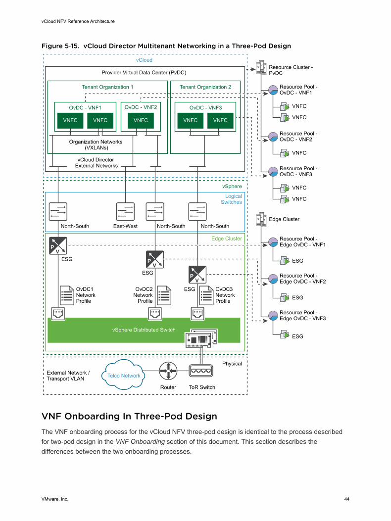
Figure 5‑15. vCloud Director Multitenant Networking in a Three-Pod Design
Tenant Organization 1
vSphere Distributed Switch
Provider Virtual Data Center (PvDC)
vCloud
vSphere
LogicalSwitches
Edge Cluster
Physical
External Network / Transport VLAN
Router ToR Switch
North-South East-West
ESG
OvDC1NetworkProfile
OvDC2Network
Profile
OvDC3NetworkProfile
ESG
ESG
OvDC - VNF1
Organization Networks (VXLANs)
vCloud Director External Networks
VNFC VNFC VNFC
OvDC - VNF2
Tenant Organization 2
North-South North-South
OvDC - VNF3
VNFC VNFC
Resource Cluster - PvDC
VNFC
VNFC
VNFC
VNFC
VNFC
Resource Pool - OvDC - VNF1
Resource Pool - OvDC - VNF2
Resource Pool - OvDC - VNF3
Edge Cluster
ESG
ESG
ESG
Resource Pool - Edge OvDC - VNF1
Resource Pool - Edge OvDC - VNF2
Resource Pool - Edge OvDC - VNF3
Telco Network
VNF Onboarding In Three-Pod DesignThe VNF onboarding process for the vCloud NFV three-pod design is identical to the process describedfor two-pod design in the VNF Onboarding section of this document. This section describes thedifferences between the two onboarding processes.
vCloud NFV Reference Architecture
VMware, Inc. 44
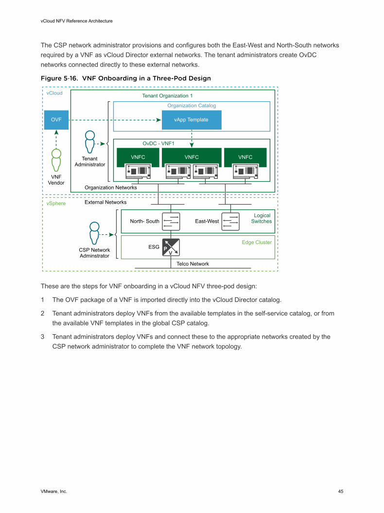
The CSP network administrator provisions and configures both the East-West and North-South networksrequired by a VNF as vCloud Director external networks. The tenant administrators create OvDCnetworks connected directly to these external networks.
Figure 5‑16. VNF Onboarding in a Three-Pod Design
Tenant Administrator
Organization Networks
External Networks
CSP NetworkAdminstrator
Tenant Organization 1vCloud
vSphere
VNFVendor
Telco Network
North- SouthLogical
SwitchesEast-West
ESGEdge Cluster
OvDC - VNF1
Organization Catalog
VNFC
OVF
VNFC
vApp Template
VNFC
These are the steps for VNF onboarding in a vCloud NFV three-pod design:
1 The OVF package of a VNF is imported directly into the vCloud Director catalog.
2 Tenant administrators deploy VNFs from the available templates in the self-service catalog, or fromthe available VNF templates in the global CSP catalog.
3 Tenant administrators deploy VNFs and connect these to the appropriate networks created by theCSP network administrator to complete the VNF network topology.
vCloud NFV Reference Architecture
VMware, Inc. 45
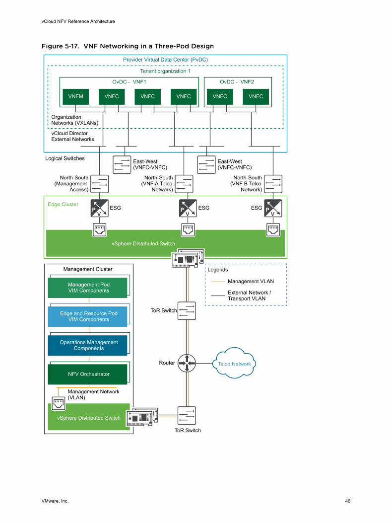
Figure 5‑17. VNF Networking in a Three-Pod Design
vSphere Distributed Switch
vSphere Distributed Switch
Tenant organization 1
Provider Virtual Data Center (PvDC)
Management Cluster
Management VLAN
Legends
External Network /Transport VLAN
Management Network (VLAN)
Router
ToR Switch
ToR Switch
North-South(Management
Access)
East-West(VNFC-VNFC)
East-West(VNFC-VNFC)
North-South(VNF A Telco
Network)
North-South(VNF B Telco
Network)
ESG ESG ESGEdge Cluster
OvDC - VNF1
Organization Networks (VXLANs)
vCloud DirectorExternal Networks
Logical Switches
OvDC - VNF2
VNFM
Management PodVIM Components
Edge and Resource PodVIM Components
Operations ManagementComponents
NFV Orchestrator
VNFC VNFC VNFC VNFC VNFC
Telco Network
vCloud NFV Reference Architecture
VMware, Inc. 46
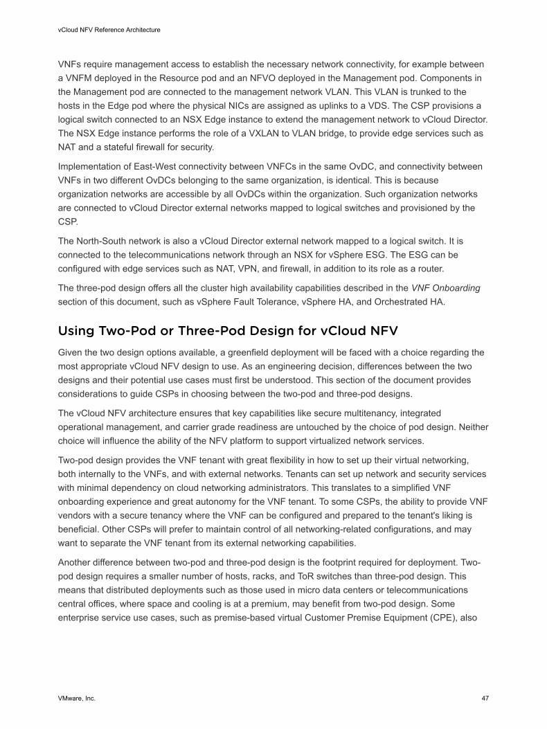
VNFs require management access to establish the necessary network connectivity, for example betweena VNFM deployed in the Resource pod and an NFVO deployed in the Management pod. Components inthe Management pod are connected to the management network VLAN. This VLAN is trunked to thehosts in the Edge pod where the physical NICs are assigned as uplinks to a VDS. The CSP provisions alogical switch connected to an NSX Edge instance to extend the management network to vCloud Director.The NSX Edge instance performs the role of a VXLAN to VLAN bridge, to provide edge services such asNAT and a stateful firewall for security.
Implementation of East-West connectivity between VNFCs in the same OvDC, and connectivity betweenVNFs in two different OvDCs belonging to the same organization, is identical. This is becauseorganization networks are accessible by all OvDCs within the organization. Such organization networksare connected to vCloud Director external networks mapped to logical switches and provisioned by theCSP.
The North-South network is also a vCloud Director external network mapped to a logical switch. It isconnected to the telecommunications network through an NSX for vSphere ESG. The ESG can beconfigured with edge services such as NAT, VPN, and firewall, in addition to its role as a router.
The three-pod design offers all the cluster high availability capabilities described in the VNF Onboardingsection of this document, such as vSphere Fault Tolerance, vSphere HA, and Orchestrated HA.
Using Two-Pod or Three-Pod Design for vCloud NFVGiven the two design options available, a greenfield deployment will be faced with a choice regarding themost appropriate vCloud NFV design to use. As an engineering decision, differences between the twodesigns and their potential use cases must first be understood. This section of the document providesconsiderations to guide CSPs in choosing between the two-pod and three-pod designs.
The vCloud NFV architecture ensures that key capabilities like secure multitenancy, integratedoperational management, and carrier grade readiness are untouched by the choice of pod design. Neitherchoice will influence the ability of the NFV platform to support virtualized network services.
Two-pod design provides the VNF tenant with great flexibility in how to set up their virtual networking,both internally to the VNFs, and with external networks. Tenants can set up network and security serviceswith minimal dependency on cloud networking administrators. This translates to a simplified VNFonboarding experience and great autonomy for the VNF tenant. To some CSPs, the ability to provide VNFvendors with a secure tenancy where the VNF can be configured and prepared to the tenant's liking isbeneficial. Other CSPs will prefer to maintain control of all networking-related configurations, and maywant to separate the VNF tenant from its external networking capabilities.
Another difference between two-pod and three-pod design is the footprint required for deployment. Two-pod design requires a smaller number of hosts, racks, and ToR switches than three-pod design. Thismeans that distributed deployments such as those used in micro data centers or telecommunicationscentral offices, where space and cooling is at a premium, may benefit from two-pod design. Someenterprise service use cases, such as premise-based virtual Customer Premise Equipment (CPE), also
vCloud NFV Reference Architecture
VMware, Inc. 47
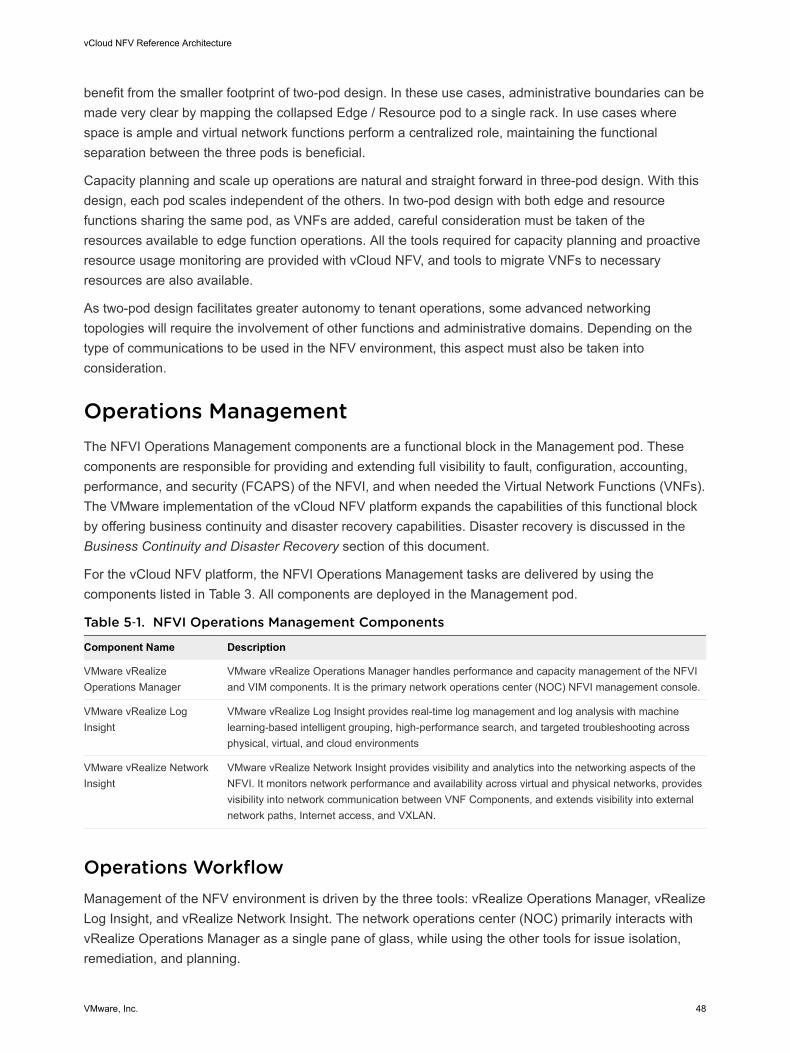
benefit from the smaller footprint of two-pod design. In these use cases, administrative boundaries can bemade very clear by mapping the collapsed Edge / Resource pod to a single rack. In use cases wherespace is ample and virtual network functions perform a centralized role, maintaining the functionalseparation between the three pods is beneficial.
Capacity planning and scale up operations are natural and straight forward in three-pod design. With thisdesign, each pod scales independent of the others. In two-pod design with both edge and resourcefunctions sharing the same pod, as VNFs are added, careful consideration must be taken of theresources available to edge function operations. All the tools required for capacity planning and proactiveresource usage monitoring are provided with vCloud NFV, and tools to migrate VNFs to necessaryresources are also available.
As two-pod design facilitates greater autonomy to tenant operations, some advanced networkingtopologies will require the involvement of other functions and administrative domains. Depending on thetype of communications to be used in the NFV environment, this aspect must also be taken intoconsideration.
Operations ManagementThe NFVI Operations Management components are a functional block in the Management pod. Thesecomponents are responsible for providing and extending full visibility to fault, configuration, accounting,performance, and security (FCAPS) of the NFVI, and when needed the Virtual Network Functions (VNFs).The VMware implementation of the vCloud NFV platform expands the capabilities of this functional blockby offering business continuity and disaster recovery capabilities. Disaster recovery is discussed in theBusiness Continuity and Disaster Recovery section of this document.
For the vCloud NFV platform, the NFVI Operations Management tasks are delivered by using thecomponents listed in Table 3. All components are deployed in the Management pod.
Table 5‑1. NFVI Operations Management Components
Component Name Description
VMware vRealizeOperations Manager
VMware vRealize Operations Manager handles performance and capacity management of the NFVIand VIM components. It is the primary network operations center (NOC) NFVI management console.
VMware vRealize LogInsight
VMware vRealize Log Insight provides real-time log management and log analysis with machinelearning-based intelligent grouping, high-performance search, and targeted troubleshooting acrossphysical, virtual, and cloud environments
VMware vRealize NetworkInsight
VMware vRealize Network Insight provides visibility and analytics into the networking aspects of theNFVI. It monitors network performance and availability across virtual and physical networks, providesvisibility into network communication between VNF Components, and extends visibility into externalnetwork paths, Internet access, and VXLAN.
Operations WorkflowManagement of the NFV environment is driven by the three tools: vRealize Operations Manager, vRealizeLog Insight, and vRealize Network Insight. The network operations center (NOC) primarily interacts withvRealize Operations Manager as a single pane of glass, while using the other tools for issue isolation,remediation, and planning.
vCloud NFV Reference Architecture
VMware, Inc. 48
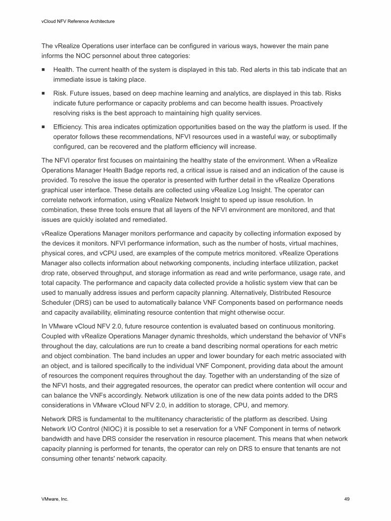
The vRealize Operations user interface can be configured in various ways, however the main paneinforms the NOC personnel about three categories:
n Health. The current health of the system is displayed in this tab. Red alerts in this tab indicate that animmediate issue is taking place.
n Risk. Future issues, based on deep machine learning and analytics, are displayed in this tab. Risksindicate future performance or capacity problems and can become health issues. Proactivelyresolving risks is the best approach to maintaining high quality services.
n Efficiency. This area indicates optimization opportunities based on the way the platform is used. If theoperator follows these recommendations, NFVI resources used in a wasteful way, or suboptimallyconfigured, can be recovered and the platform efficiency will increase.
The NFVI operator first focuses on maintaining the healthy state of the environment. When a vRealizeOperations Manager Health Badge reports red, a critical issue is raised and an indication of the cause isprovided. To resolve the issue the operator is presented with further detail in the vRealize Operationsgraphical user interface. These details are collected using vRealize Log Insight. The operator cancorrelate network information, using vRealize Network Insight to speed up issue resolution. Incombination, these three tools ensure that all layers of the NFVI environment are monitored, and thatissues are quickly isolated and remediated.
vRealize Operations Manager monitors performance and capacity by collecting information exposed bythe devices it monitors. NFVI performance information, such as the number of hosts, virtual machines,physical cores, and vCPU used, are examples of the compute metrics monitored. vRealize OperationsManager also collects information about networking components, including interface utilization, packetdrop rate, observed throughput, and storage information as read and write performance, usage rate, andtotal capacity. The performance and capacity data collected provide a holistic system view that can beused to manually address issues and perform capacity planning. Alternatively, Distributed ResourceScheduler (DRS) can be used to automatically balance VNF Components based on performance needsand capacity availability, eliminating resource contention that might otherwise occur.
In VMware vCloud NFV 2.0, future resource contention is evaluated based on continuous monitoring.Coupled with vRealize Operations Manager dynamic thresholds, which understand the behavior of VNFsthroughout the day, calculations are run to create a band describing normal operations for each metricand object combination. The band includes an upper and lower boundary for each metric associated withan object, and is tailored specifically to the individual VNF Component, providing data about the amountof resources the component requires throughout the day. Together with an understanding of the size ofthe NFVI hosts, and their aggregated resources, the operator can predict where contention will occur andcan balance the VNFs accordingly. Network utilization is one of the new data points added to the DRSconsiderations in VMware vCloud NFV 2.0, in addition to storage, CPU, and memory.
Network DRS is fundamental to the multitenancy characteristic of the platform as described. UsingNetwork I/O Control (NIOC) it is possible to set a reservation for a VNF Component in terms of networkbandwidth and have DRS consider the reservation in resource placement. This means that when networkcapacity planning is performed for tenants, the operator can rely on DRS to ensure that tenants are notconsuming other tenants' network capacity.
vCloud NFV Reference Architecture
VMware, Inc. 49
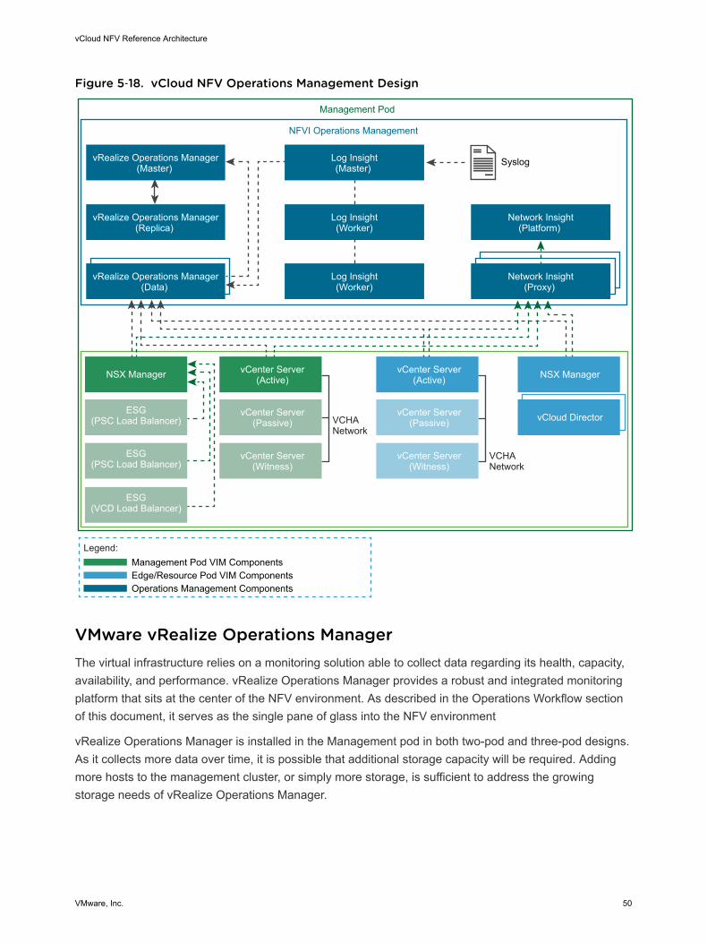
Figure 5‑18. vCloud NFV Operations Management Design
vCenter Server(Active)
vCenter Server(Passive)
vCenter Server(Witness)
vCloud DirectorVCHANetwork
Legend:
Edge/Resource Pod VIM ComponentsManagement Pod VIM Components
Operations Management Components
Management Pod
NSX Manager NSX Manager
NFVI Operations Management
vRealize Operations Manager(Data)
Log Insight(Worker)
Network Insight(Proxy)
ESG(PSC Load Balancer)
ESG(PSC Load Balancer)
ESG(VCD Load Balancer)
vCenter Server(Active)
vCenter Server(Passive)
vCenter Server(Witness)
VCHANetwork
vRealize Operations Manager(Master)
Log Insight(Master)
Syslog
Network Insight(Platform)
vRealize Operations Manager(Replica)
Log Insight(Worker)
VMware vRealize Operations ManagerThe virtual infrastructure relies on a monitoring solution able to collect data regarding its health, capacity,availability, and performance. vRealize Operations Manager provides a robust and integrated monitoringplatform that sits at the center of the NFV environment. As described in the Operations Workflow sectionof this document, it serves as the single pane of glass into the NFV environment
vRealize Operations Manager is installed in the Management pod in both two-pod and three-pod designs.As it collects more data over time, it is possible that additional storage capacity will be required. Addingmore hosts to the management cluster, or simply more storage, is sufficient to address the growingstorage needs of vRealize Operations Manager.
vCloud NFV Reference Architecture
VMware, Inc. 50
Since vRealize Operations Manager is the central management component in the vCloud NFV platform,its availability to the operator is essential. vRealize Operations Manager supports High Availability (HA).HA creates a master replica for the vRealize Operations Manager master node and protects the analyticscluster against the loss of a node. With HA, data stored on the master node is always completely backedup on the master replica node. To enable HA, at least one other data node must be deployed in additionto the master node. For more information see vRealize Operations Manager vApp Deployment andConfiguration Guide.
VMware vRealize Operations Management PackVMware vRealize Operations Manager collects structure data from various sources, including gatheringdata from adapters connected to source servers. For this mechanism to work, vRealize OperationsManager is configured to communicate with source servers using an authorized user account. If the useraccount has limited access to objects in the source server, it sees only the data for which the account haspermissions. At a minimum, the user account must have read privileges across the objects from which itwill collect data. A collection of management packs is available on VMware Solution Exchange.
To minimize the traffic between vCenter Server and the vRealize Operations Manager, the vCenter ServerAdapter is installed with a five minute collection interval.
VNF vendors can create plug-ins, which are interfaces between vRealize Operations Manager andexternal components that require management. Plug-in development requires an understanding of thevRealize Operations Manager inventory model, the management functions that plug-ins implement.These include auto-discovery and monitoring. More information is available at Endpoint OperationsManagement Agent Plugin Development Kit.
VMware vRealize Operations Manager LoggingAudit logs are used to track configuration changes performed by authenticated users to see who initiateda change or scheduled a job that performed the change. All audit logs are forwarded to vRealize LogInsight.
VMware vRealize Operations Manager AlertsWhen alerts are generated in vRealize Operations Manager, they appear in the alert details and objectdetails windows. Alerts can also be configured to be sent to other applications using one or moreoutbound alert options.
To configure notification options, the operator must specify which alerts are sent out with the standardemail, REST, SNMP traps, and log file outbound alert plug-ins. The decision to use a specific alertingmethod is implementation specific and is typically driven by the external monitoring and managementtools available.
vCloud NFV Reference Architecture
VMware, Inc. 51
VMware vRealize Log InsightMware vRealize Log Insight is deployed in the Management pod using a single cluster configuration,which consists of a minimum of three nodes leveraging the Log Insight Integrated Load Balancer (ILB). Asingle log message is only present in one location within the cluster at a time. The cluster remains up andavailable to ingest data and serve queries during any temporary unavailability of a single node.
Data is collected using the syslog protocol or an API. All NSX Manager syslog information, distributedfirewall logs, and NSX Edge Services Gateway syslog information is sent to vRealize Log Insight. EachvCloud Director cell produces logs that are sent to vRealize Log Insight as well.
Additional vCloud Director troubleshooting and API access logs are stored locally on the vCloud Directorcells. These logs can be forwarded by creating an additional logger that can send diagnostics logs tovRealize Log Insight. For more information see Enabling Centralized Logging in VMware vCloud Director.
VMware vRealize Log Insight Content PackvRealize Log Insight gathers log events from multiple sources, and through special content packs deliverssolution specific dashboards to perform log analytics, by using redefined alerts. For additional informationabout vRealize Log Insight solutions, see VMware Solution Exchange.
VMware vRealize Log Insight ArchivingArchiving is primarily a long term retention tool. The process copies raw data to an external NFS storagelocation. Archives are much smaller than indexes, but require indexing if they are loaded back into thevRealize Log Insight system. For additional information about vRealize Log Insight archiving, see the vRealize Log Insight page .
VMware vRealize Network InsightRealize Network Insight is installed in the Management pod in both two-pod and three-pod designs. In anideal situation, vRealize Network Insight is configured to monitor all networking-related components in theNFVI. Naturally, vRealize Network Insight can connect to the vCloud NFV components relating tonetworking: vSphere and NSX for vSphere. It can also be configured to monitor a myriad of physicaldevices such as Dell switches, Cisco Nexus and Catalyst switches, and Arista, Juniper Networks, HewlettPackard Enterprise, Brocade, and Palo Alto Networks switches.
The vRealize Network Insight architecture consists of a platform VM, a proxy VM, and data sources. Therole of the platform VM within the architecture is to perform analytics, storage, and to provide a userinterface into the data. The proxy VM, or the collector, collects data from sources using various protocolssuch as HTTPS, SSH, CLI, and SNMP, depending on the source and the configuration. A variety of datasources are supported, including VMware vCenter, NSX, firewalls, and various switch vendors. To providea complete overview of the NFV environment, vRealize Network Insight is connected to the vCenterServer that is used to operate the edge and resource clusters as is shown in Figure 21.
vCloud NFV Reference Architecture
VMware, Inc. 52
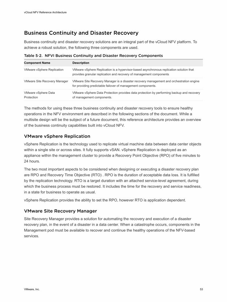
Business Continuity and Disaster RecoveryBusiness continuity and disaster recovery solutions are an integral part of the vCloud NFV platform. Toachieve a robust solution, the following three components are used.
Table 5‑2. NFVI Business Continuity and Disaster Recovery Components
Component Name Description
VMware vSphere Replication VMware vSphere Replication is a hypervisor-based asynchronous replication solution thatprovides granular replication and recovery of management components
VMware Site Recovery Manager VMware Site Recovery Manager is a disaster recovery management and orchestration enginefor providing predictable failover of management components.
VMware vSphere DataProtection
VMware vSphere Data Protection provides data protection by performing backup and recoveryof management components.
The methods for using these three business continuity and disaster recovery tools to ensure healthyoperations in the NFV environment are described in the following sections of the document. While amultisite design will be the subject of a future document, this reference architecture provides an overviewof the business continuity capabilities built into vCloud NFV.
VMware vSphere ReplicationvSphere Replication is the technology used to replicate virtual machine data between data center objectswithin a single site or across sites. It fully supports vSAN. vSphere Replication is deployed as anappliance within the management cluster to provide a Recovery Point Objective (RPO) of five minutes to24 hours.
The two most important aspects to be considered when designing or executing a disaster recovery planare RPO and Recovery Time Objective (RTO) . RPO is the duration of acceptable data loss. It is fulfilledby the replication technology. RTO is a target duration with an attached service-level agreement, duringwhich the business process must be restored. It includes the time for the recovery and service readiness,in a state for business to operate as usual.
vSphere Replication provides the ability to set the RPO, however RTO is application dependent.
VMware Site Recovery ManagerSite Recovery Manager provides a solution for automating the recovery and execution of a disasterrecovery plan, in the event of a disaster in a data center. When a catastrophe occurs, components in theManagement pod must be available to recover and continue the healthy operations of the NFV-basedservices.
vCloud NFV Reference Architecture
VMware, Inc. 53
To ensure robust business continuity and disaster recovery, network connectivity between the protectedand recovery sites is required, with enough bandwidth capacity to replicate the management componentsusing vSphere Replication. Each site must have an instance of vCenter Server that governs theManagement pod and its ESXi hosts, and a Site Recovery Manager server and vSphere Replicationappliance to orchestrate the disaster recovery workflows and replicate content across the sites. Theprotected site provides business critical services, while the recovery site is an alternative infrastructure onwhich services are recovered in the event of a disaster.
Networking Considerations
Moving a service from one site to another represents a networking challenge in terms of maintaining IPaddressing, security policies, and bandwidth ensuring ample network capacity. Some of these challenges,such as IP addressing, are managed by using NSX for vSphere.
Distributed Resource Scheduler Considerations
Some management components for the vCloud NFV platform such as NSX for vSphere, Edge ServicesGateway, PSCs, vCloud Director cells, vRealize Operations Manager, and vRealize Log Insight havespecific affinity or anti-affinity rules configured for availability. When protected management componentsare recovered at a recovery site, DRS rules, reservations, and limits are not carried over as part of therecovery plan. However, it is possible to manually configure rules, reservations, and limits on placeholdervirtual machines at the recovery site, during the platform build.
Inventory Mappings
Elements in the vCenter Server inventory list can be mapped from the protected site to their vCenterServer inventory counterparts on the recovery site. Such elements include virtual machine folders,clusters or resource pools, and networks. All items within a single data center on the protected site mustmap to a single data center on the recovery site.
These inventory mapping details are used across both the protected and recovery sites:
n Resource mapping maps cluster objects on the protected site to cluster objects on the recovery site.
n Folder mapping maps the folder structures like data centers or virtual machine folders on theprotected site to folder structures on the recovery site
n Network mapping maps the management networks on the protected site to management networks onthe recovery site.
VNF Recovery Considerations
Every vendor must provide a specific strategy for disaster recovery for any VNF managed directly by theVNF Managers.
Protection Groups
A protection group is a group of management components at the protected site that can fail over togetherto the recovery site during testing and recovery. All protected management components are placed withina single protection group.
Recovery Plans
vCloud NFV Reference Architecture
VMware, Inc. 54
Recovery plans are the run books associated with a disaster recovery scenario. A recovery plandetermines which management components are started, what needs to be powered down, which scriptsto run, the startup order, and the overall automated execution of the failover.
A complete site failure is the only scenario that invokes a disaster recovery. There is no requirement forrecovery plans to handle planned migrations or to move a single failed application within the managementcluster. A single recovery plan is created for the automated failover of the primary site, and the placementof management components into priority groups ensures the correct startup order.
The recovery of the resource cluster, edge cluster, vCenter Server, and NSX Manager are required tomaintain management capabilities where additional physical data centers are managed within the site.
VMware vSphere Data ProtectionTvSphere Data Protection is a disk-based backup and recovery solution that is fully integrated withvCenter Server and vSphere Web Client to enable centralized management of backup and restore tasks,while storing backups in deduplicated backup storage. Managing the backup and restore tasks isaccomplished through the vSphere Data Protection UI, which is an add on plug-in to the vSphere WebClient.
vSphere Data Protection creates image-level backups, which are integrated with the VMware vSphere®
vStorage APIs for Data Protection, a feature set within VMware vSphere used to offload the backupprocessing overhead from a virtual machine to the VDP appliance. The VDP appliance communicateswith the vCenter Server to make a snapshot of the .vmdk files in a virtual machine. Deduplication takesplace within the appliance, using a patented variable length deduplication technology.
vSphere Data Protection is distributed in a prepackaged OVA file. The vSphere Data Protection applianceis responsible for the backup and restore of the management components residing within themanagement cluster. vSphere Data Protection is configured so the appliance backs up the data to adeduplicated backup datastore, which is different from the datastore hosting management components.
vSphere Data Protection protects the management cluster through the vCenter Server managementlayer. Connectivity through vCenter Server provides vSphere Data Protection with visibility to all ESXiservers in the management clusters, and therefore to all management components that must be backedup.
The initial configuration of the vSphere Data Protection appliance should be set to 6 terabytes. Theadditional disk space required above the usable capacity of the appliance is for creating and managingcheckpoints. Backups can be configured to protect required components from the management cluster. Ina disaster recovery or data loss event, the protected components can be restored to resume normalservices based on the RPO. The target location must meet the minimum performance requirements formitigation.
RPO. vSphere Data Protection can perform daily backups at scheduled intervals for required componentswithin the management cluster. The RPO value and the backup start time must be set as required basedon the business needs. It is recommended to schedule backups during off-peak business hours.
vCloud NFV Reference Architecture
VMware, Inc. 55
Retention Policies. Retention policies are the properties of a backup job. It is important to groupmanagement components in a backup job by business priorities and by the retention requirements setbased on the business needs.
Monitoring. CPU, memory, network, disk performance, and the capacity of the vSphere Data Protectionappliance are monitored by vRealize Operations Manager, with syslog events sent to vRealize LogInsight. Capacity can be viewed through vSphere Data Protection reports.
For backup of vCenter components and NSX Manager data, respective inbuilt backup mechanisms canbe leveraged.
Carrier GradeCarrier grade attributes are injected into every layer of the vCloud NFV platform. High availability that is acore pillar in the architecture and a crucial requirement in every CSP network, spans the entire platform.When discussing management components of the platform, the various redundancy mechanisms thatallow them to be highly available are highlighted, as are details of the ways in which networking elementscan be made highly redundant with the use of routing protocols and NIC teaming. The NFVI virtualizationlayer also provides mechanisms to the Virtual Network Functions to enhance and improve theiravailability. These include vSphere Fault Tolerance (FT), High Availability (HA), and Orchestrated HA. .
Even though tuning the vCloud NFV platform for performance spans the NFVI, VNFs, and VIM, since it isapplicable to specific VNFs, performance architecture recommendations are grouped in this section.
PerformanceETSI classifies NFV workloads into three categories: management, control, and data plane. Based onexperience deploying vCloud NFV in various CSP networks, data plane workloads are further divided intointensive workloads, and workloads that behave as management and control plane workloads. The latterclass of data plane workloads have been proven to function well on the vCloud NFV platform, as hasbeen described in this reference architecture. Further information regarding these workloads is providedin the VNF Performance in Distributed Deployments section of this document. For data plane intensiveVNFs hosted on the vCloud NFV platform, specific design considerations are provided in the followingsection of this document.
ETSI classifies NFV workloads into three categories: management, control, and data plane. Based onexperience deploying vCloud NFV in various CSP networks, data plane workloads are further divided intointensive workloads, and workloads that behave as management and control plane workloads. The latterclass of data plane workloads have been proven to function well on the vCloud NFV platform, as hasbeen described in this reference architecture. Further information regarding these workloads is providedin the VNF Performance in Distributed Deployments section of this document. For data plane intensiveVNFs hosted on the vCloud NFV platform, specific design considerations are provided in the followingsection of this document.
vCloud NFV Reference Architecture
VMware, Inc. 56
Data Plane Intensive Design FrameworkTwo parties are involved in the successful deployment and operations of a data plane intensive VNF: theVNF vendor and the NFVI operator. Both parties must be able to understand the performancerequirements of the VNF, and share an understanding of the VNF design. They must also be willing totune the entire stack from the physical layer to the VNF itself, for the demands data plane intensiveworkloads place on the system. The responsibilities of the two parties are described as follows:
Virtual Network Function Design and Configuration. The vendor supplying the VNF is expected totune the performance of the VNF components and optimize their software. Data plane intensiveworkloads benefit from the use of a Data Plane Development Kit (DPDK) to speed up VNFC packetprocessing and optimize the handling of packets off loading to the virtual NIC. Use of the VMwareVMXNET3 paravirtualized network interface card (NIC) is a best practice VNF design for performancedemanding VNFs. VMXNET3 is the most advanced virtual NIC on the VMware platform and has beencontributed to the Linux community, making it ubiquitous in many Linux distributions.
Once the VNF is created by its supplier, there are several VNFC level configurations that are essential tothese types of workloads. Dedicated resource allocation, for the VNFC and the networking-relatedprocesses associated with it, can be configured and guaranteed through the use of two main parameters:Latency Sensitivity and System Contexts. Both parameters are discussed in detail in a separate whitepaper.
Another aspect essential to the performance of a data plane intensive VNF is the number of virtual CPUsrequired by the VNFC. Modern multiprocessor server architecture is based on a grouping of resources,including memory and PCIe cards, into Non-Uniform Memory Access (NUMA) nodes. Resource usagewithin a NUMA node is fast and efficient. However, when NUMA boundaries are crossed, due to thephysical nature of the QPI bridge between the two nodes, speed is reduced and latency increases.VNFCs that participate in the data plane path are advised to contain the virtual CPU, memory, andphysical NIC associated with them to a single NUMA node for optimal performance.
NFVI Design Considerations. Once the VNFs are tuned for performance, the underlying physical andvirtual infrastructure must be prepared with data plane intensive workloads in mind. The modular natureof the vCloud NFV platform facilitates the construction of an NFVI aimed at data plane intensiveworkloads, while still using the same VIM and FCAPS components used elsewhere in the architecture.The same VIM and FCAPS components are employed for the building of a data plane intensive NFVI andin the governing of management and control plane VNFs.
Data plane intensive VNFs tend to serve a central role in a CSP network: as a Packet Gateway in amobile core deployment, a Provider Edge router (PE) in an MPLS network, or a media gateway in an IMSnetwork. As a result, these VNFs are positioned in a centralized location in the CSP network: the datacenter. With their crucial role, these VNFs are typically static and are used by the central organization tooffer services to a large customer base. For example, a virtualized Packet Gateway in a mobile corenetwork will serve a large geographical region as the central termination point for subscriber connections.Once the VNF is deployed, it is likely to remain active for a long duration, baring any NFVI life cycleactivities such as upgrades or other maintenance.
vCloud NFV Reference Architecture
VMware, Inc. 57
This aggregation role translates into a certain sizing requirement. The VNFs must serve many customers,which is the reason for their data plane intensive nature. Such VNFs include many components to allowthem to be scaled and managed. These components include at a minimum an OAM function, packetprocessing functions, VNF-specific load balancing, and often log collection and monitoring. Individualcomponents can also require significant resources to provide large scale services.
The central position of these VNFs, their sizeable scale, and their static nature, all suggest that dedicatedresources are required to achieve their expected performance goals. These dedicated resources beginwith hosts using powerful servers with high performing network interface cards. The servers are groupedtogether into a cluster that is dedicated to data plane intensive workloads. Using the same constructsintroduced earlier in this document, the data plane intensive cluster is consumed by vCloud Director andis made into a PvDC. VNFs are then onboarded into the vCloud Director catalog for deployment.
To be able to benefit from virtual machine specific configuration such as Latency Sensitivity, the allocationmodel configured for use by tenants in the data plane intensive workload OvDC is Reservation Pool. TheReservation Pool allocation model allows VNFs to be configured with the CPU reservation set tomaximum, removing any CPU usage limits. The same applies to the memory reservation and limit. Bothconfigurations are prerequisites to using the Latency Sensitivity feature, which is the prerequisite for usingthe System Contexts feature.
NUMA affinity is ensured by combining VNFC specific configuration and the distributed resourcescheduler, vSphere DRS. The NUMA affinity parameter should be configured in the Virtual MachineAdvanced Parameters. Then, with the use of VM anti-affinity rules, vSphere DRS will place the virtualmachines into an empty NUMA node.
With the architecture provided in this section, data plane intensive workloads are ensured the resourcesthey require, to benefit from platform modularity while meeting carrier grade performance requirements.Specific configuration and VNF design guidelines are detailed in a performance white paper on thesubject.
vCloud NFV Reference Architecture
VMware, Inc. 58
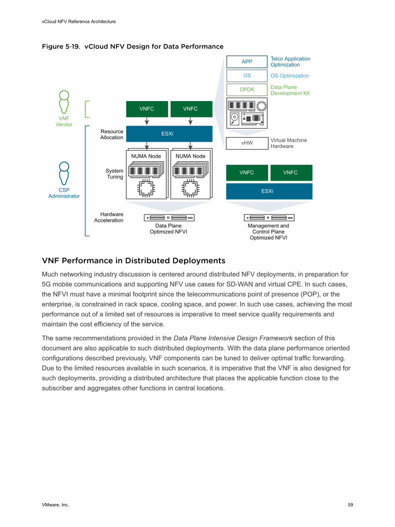
Figure 5‑19. vCloud NFV Design for Data Performance
Telco ApplicationOptimization
OS Optimization
Data PlaneDevelopment Kit
Virtual MachineHardware
ResourceAllocation
SystemTuning
HardwareAcceleration
CSPAdministrator
VNFVendor
APP
OS
DPDK
vHW
NUMA Node NUMA Node
ESXi
VNFCVNFC
Management andControl Plane
Optimized NFVI
ESXi
VNFCVNFC
Data PlaneOptimized NFVI
VNF Performance in Distributed DeploymentsMuch networking industry discussion is centered around distributed NFV deployments, in preparation for5G mobile communications and supporting NFV use cases for SD-WAN and virtual CPE. In such cases,the NFVI must have a minimal footprint since the telecommunications point of presence (POP), or theenterprise, is constrained in rack space, cooling space, and power. In such use cases, achieving the mostperformance out of a limited set of resources is imperative to meet service quality requirements andmaintain the cost efficiency of the service.
The same recommendations provided in the Data Plane Intensive Design Framework section of thisdocument are also applicable to such distributed deployments. With the data plane performance orientedconfigurations described previously, VNF components can be tuned to deliver optimal traffic forwarding.Due to the limited resources available in such scenarios, it is imperative that the VNF is also designed forsuch deployments, providing a distributed architecture that places the applicable function close to thesubscriber and aggregates other functions in central locations.
vCloud NFV Reference Architecture
VMware, Inc. 59
Authors and Contributors 6The following authors co-wrote this paper:n Indranil Bal, Solution Consultant, NFV Solutions Engineering, VMware
n Pradip Kadam, Solution Consultant, NFV Solutions Engineering, VMware
n Jambi Ganbar, Technical Solutions Manager, NFV Solutions Engineering, VMware
Many thanks for contributions from:
n Danny Lin, Senior Director, NFV Solutions Engineering, VMware
n Michelle Han, Director, Solutions Testing and Validation, NFV Solutions Engineering, VMware
n Andrea Li, Lead Solutions Test Architect, NFV Solutions Engineering, VMware
n Jason Sauviac, Lead Solutions Architect, NFV Solutions Engineering , VMware
n Suresh Babu Nekkalapudi, Solutions Architect, NFV Solutions Engineering, VMware
n Sumit Verdi, NFV Lighthouse Solutions Director, Telco NFV group, VMware
n Frank Escaros-Buechsel, Solutions Architect, NFV, VMware
n Christian Hasner, Solutions Architect, NFV, VMware
n Neil Moore, Staff Solutions Architect, NFV, VMware
n Henrik Oberg, NFV Specialist, VMware
n Mauricio Valdueza, NFV Strategist, VMware
VMware, Inc. 60


