Eddy CUrrent brake Compatibility€¦ · · 2015-10-0111.1.1 Brake system / Logical functional...
33
ECUC Deliverable draft D6.1-1 Due date: 30 th June 2015 FP7 TRANSPORT Contract No. 314244 1 September 2012 - 31 August 2015 Page 1 of 33 DELIVERABLE D.6.1 Engineering guidelines for ECB Contract number : 314244 Project acronym : ECUC Project title : EDDY CURRENT BRAKE COMPATIBILITY Deliverable number : D6.1 Nature : Dissemination level : PU (Public) Report date : 30 th July 2015 Author(s): Stefan, Aurich : chapter 8, 9 Henry, Lehmann chapter 6, 10 Other chapters both Partners contributed : AT, CEIT, DB, NRIL Contact : Dr.-Ing. Henry Lehmann, Knorr-Bremse GmbH, Beethovengasse 43 – 45, A-2340 Mödling Tel.: +43 2236 409 2383, Email: [email protected] ECUC Eddy CUrrent brake Compatibility The ECUC project was funded by the European Commission under the 7 th Framework Programme (FP7) –Transport Coordinator: CEIT
Transcript of Eddy CUrrent brake Compatibility€¦ · · 2015-10-0111.1.1 Brake system / Logical functional...
ECUC Deliverable draft D6.1-1 Due date: 30th June 2015
FP7 TRANSPORT Contract No. 314244 1 September 2012 - 31 August 2015 Page 1 of 33
DELIVERABLE D.6.1 Engineering guidelines for ECB
Contract number : 314244
Project acronym : ECUC
Project title : EDDY CURRENT BRAKE COMPATIBILITY
Deliverable number : D6.1
Nature :
Dissemination level : PU (Public)
Report date : 30th July 2015
Author(s): Stefan, Aurich : chapter 8, 9 Henry, Lehmann chapter 6, 10 Other chapters both
Partners contributed : AT, CEIT, DB, NRIL
Contact : Dr.-Ing. Henry Lehmann, Knorr-Bremse GmbH, Beethovengasse 43 – 45, A-2340 Mödling Tel.: +43 2236 409 2383, Email: [email protected]
ECUC Eddy CUrrent brake Compatibility
The ECUC project was funded by the European Commission under the 7th Framework Programme (FP7) –Transport
Coordinator: CEIT
ECUC Deliverable D6.1-1 Due date: 30th June 2015
FP7 TRANSPORT Contract No. 314244 1 September 2012 - 31 August 2015 Page 2 of 33
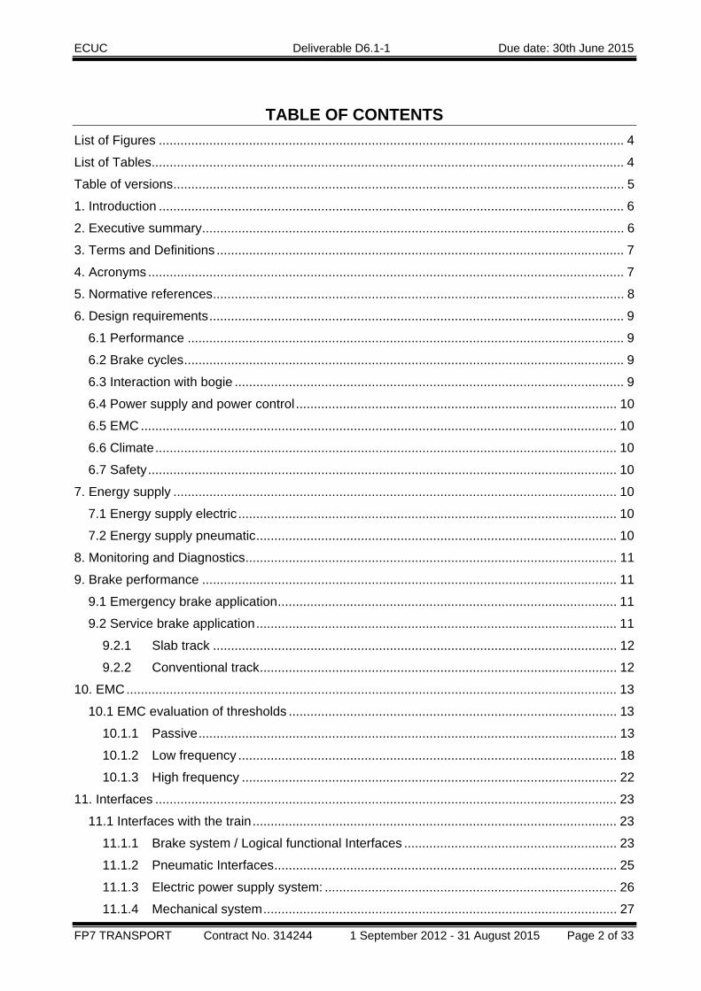
TABLE OF CONTENTS List of Figures ................................................................................................................................. 4
List of Tables ................................................................................................................................... 4
Table of versions ............................................................................................................................. 5
1. Introduction ................................................................................................................................. 6
2. Executive summary ..................................................................................................................... 6
3. Terms and Definitions ................................................................................................................. 7
4. Acronyms .................................................................................................................................... 7
5. Normative references .................................................................................................................. 8
6. Design requirements ................................................................................................................... 9
6.1 Performance ......................................................................................................................... 9
6.2 Brake cycles .......................................................................................................................... 9
6.3 Interaction with bogie ............................................................................................................ 9
6.4 Power supply and power control ......................................................................................... 10
6.5 EMC .................................................................................................................................... 10
6.6 Climate ................................................................................................................................ 10
6.7 Safety .................................................................................................................................. 10
7. Energy supply ........................................................................................................................... 10
7.1 Energy supply electric ......................................................................................................... 10
7.2 Energy supply pneumatic .................................................................................................... 10
8. Monitoring and Diagnostics ....................................................................................................... 11
9. Brake performance ................................................................................................................... 11
9.1 Emergency brake application .............................................................................................. 11
9.2 Service brake application .................................................................................................... 11
9.2.1 Slab track ................................................................................................................ 12
9.2.2 Conventional track ................................................................................................... 12
10. EMC ........................................................................................................................................ 13
10.1 EMC evaluation of thresholds ........................................................................................... 13
10.1.1 Passive .................................................................................................................... 13
10.1.2 Low frequency ......................................................................................................... 18
10.1.3 High frequency ........................................................................................................ 22
11. Interfaces ................................................................................................................................ 23
11.1 Interfaces with the train ..................................................................................................... 23
11.1.1 Brake system / Logical functional Interfaces ........................................................... 23
11.1.2 Pneumatic Interfaces ............................................................................................... 25
11.1.3 Electric power supply system: ................................................................................. 26
11.1.4 Mechanical system .................................................................................................. 27
ECUC Deliverable D6.1-1 Due date: 30th June 2015
FP7 TRANSPORT Contract No. 314244 1 September 2012 - 31 August 2015 Page 3 of 33
11.2 Interfaces infrastructure: ................................................................................................... 30
11.2.1 Signaling devices .................................................................................................... 30
11.2.2 Rail .......................................................................................................................... 31
11.2.3 Rail equipment ........................................................................................................ 32
11.2.4 Operation ................................................................................................................. 32
12. Handling during maintenance ................................................................................................. 33
ECUC Deliverable D6.1-1 Due date: 30th June 2015
FP7 TRANSPORT Contract No. 314244 1 September 2012 - 31 August 2015 Page 4 of 33
LIST OF FIGURES Figure 1: heuristic model of electromagnetic interferences .......................................................... 13
Figure 2: range of lateral displacement ......................................................................................... 14
Figure 3: example in our test ........................................................................................................ 17
Figure 4: magnetic stray field (x-component) dependant on speed .............................................. 19
Figure 5: magnetic stray field (y-component) dependant on speed .............................................. 19
Figure 6: magnetic stray field (z-component) dependant on speed .............................................. 20
Figure 7: raster of measurement in vertical and horizontal plane ................................................. 21
Figure 8: overview of logical interfaces ......................................................................................... 23
Figure 9: relevant interfaces in release position ........................................................................... 28
Figure 10: relevant interfaces in brake position ............................................................................ 29
Figure 11: local brake force vs. brake distance ............................................................................ 31
Figure 12: vertical load of ECB ..................................................................................................... 32
LIST OF TABLES Table 1: example of test template “wheel flange sensor” for ECB 154 R ..................................... 15
Table 2: example of test template “wheel sensor” for position ...................................................... 16
Table 3: example of test template “wheel sensor” for impedance loads ....................................... 18
Table 4: harmonic of stray field depend on speed ........................................................................ 18
Table 5: example of template of positions for stray field measurements ...................................... 21
Table 6: example of template of positions for high frequency stray field measurements ............. 22
Table 7: parameters of electric interface ....................................................................................... 26
Table 8: interfaces in release position .......................................................................................... 28
Table 9: interface in brake position ............................................................................................... 30
ECUC Deliverable D6.1-1 Due date: 30th June 2015
FP7 TRANSPORT Contract No. 314244 1 September 2012 - 31 August 2015 Page 5 of 33
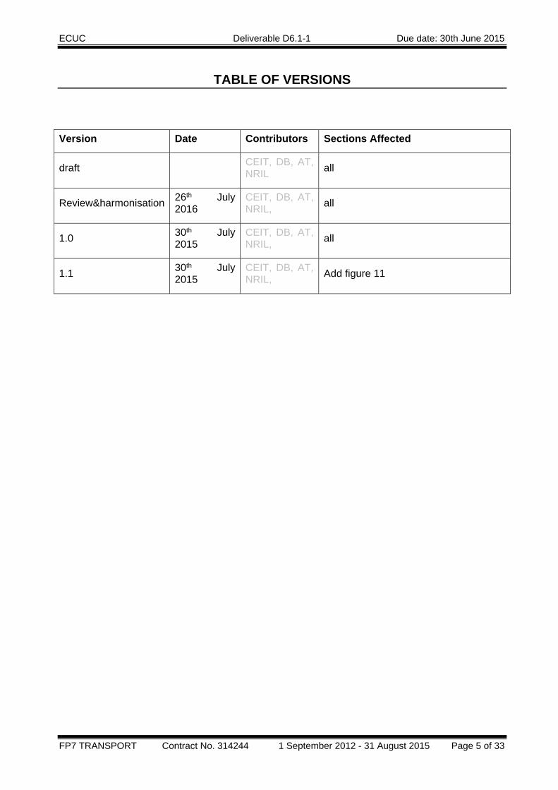
TABLE OF VERSIONS
Version Date Contributors Sections Affected
draft CEIT, DB, AT, NRIL all
Review&harmonisation 26th July 2016
CEIT, DB, AT, NRIL, all
1.0 30th July 2015
CEIT, DB, AT, NRIL, all
1.1 30th July 2015
CEIT, DB, AT, NRIL, Add figure 11
ECUC Deliverable D6.1-1 Due date: 30th June 2015
FP7 TRANSPORT Contract No. 314244 1 September 2012 - 31 August 2015 Page 6 of 33
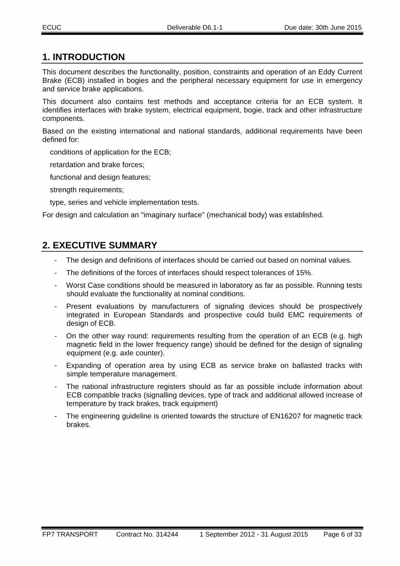
1. INTRODUCTION This document describes the functionality, position, constraints and operation of an Eddy Current Brake (ECB) installed in bogies and the peripheral necessary equipment for use in emergency and service brake applications.
This document also contains test methods and acceptance criteria for an ECB system. It identifies interfaces with brake system, electrical equipment, bogie, track and other infrastructure components.
Based on the existing international and national standards, additional requirements have been defined for:
� conditions of application for the ECB;
� retardation and brake forces;
� functional and design features;
� strength requirements;
� type, series and vehicle implementation tests.
For design and calculation an "imaginary surface" (mechanical body) was established.
2. EXECUTIVE SUMMARY - The design and definitions of interfaces should be carried out based on nominal values.
- The definitions of the forces of interfaces should respect tolerances of 15%.
- Worst Case conditions should be measured in laboratory as far as possible. Running tests should evaluate the functionality at nominal conditions.
- Present evaluations by manufacturers of signaling devices should be prospectively integrated in European Standards and prospective could build EMC requirements of design of ECB.
- On the other way round: requirements resulting from the operation of an ECB (e.g. high magnetic field in the lower frequency range) should be defined for the design of signaling equipment (e.g. axle counter).
- Expanding of operation area by using ECB as service brake on ballasted tracks with simple temperature management.
- The national infrastructure registers should as far as possible include information about ECB compatible tracks (signalling devices, type of track and additional allowed increase of temperature by track brakes, track equipment)
- The engineering guideline is oriented towards the structure of EN16207 for magnetic track brakes.

ECUC Deliverable D6.1-1 Due date: 30th June 2015
FP7 TRANSPORT Contract No. 314244 1 September 2012 - 31 August 2015 Page 7 of 33
3. TERMS AND DEFINITIONS Wheel flange sensor
This type of signalling sensors generate a magnetic stray field at one side of the rail and the magnetic stray field is focused on the flange of the wheel. Receiver and antenna are on same side of rail.
Wheel sensor
This type of signalling sensors has on one side of rail the receiver and on other side the antenna and generates a magnetic field around the rail.
Track circuit See D2.2
coefficient c This coefficient of speed (c) is defined by the ratio between magnetic stray field density at maximum speed divided by the magnetic stray field density in standstill.
4. ACRONYMS ECB Eddy current brake
ED Electrodynamic brake
ETCS European Train Control System
LZB Linienzugbeeinflussung
TCMS Train Control and Monitoring System
TSI Technical specification of interoperability
WP Work package
ECUC Deliverable D6.1-1 Due date: 30th June 2015
FP7 TRANSPORT Contract No. 314244 1 September 2012 - 31 August 2015 Page 8 of 33
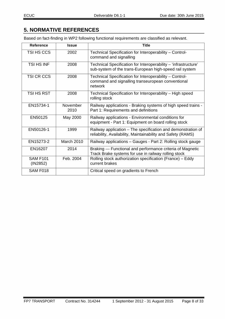
5. NORMATIVE REFERENCES Based on fact-finding in WP2 following functional requirements are classified as relevant.
Reference Issue Title
TSI HS CCS 2002 Technical Specification for Interoperability – Control-command and signalling
TSI HS INF 2008 Technical Specification for Interoperability – ‘infrastructure’ sub-system of the trans-European high-speed rail system
TSI CR CCS 2008 Technical Specification for Interoperability – Control-command and signalling transeuropean conventional network
TSI HS RST 2008 Technical Specification for Interoperability – High speed rolling stock
EN15734-1 November 2010
Railway applications - Braking systems of high speed trains -Part 1: Requirements and definitions
EN50125 May 2000 Railway applications - Environmental conditions for equipment - Part 1: Equipment on board rolling stock
EN50126-1 1999 Railway application – The specification and demonstration of reliability, Availability, Maintainability and Safety (RAMS)
EN15273-2 March 2010 Railway applications – Gauges - Part 2: Rolling stock gauge
EN16207 2014 Braking — Functional and performance criteria of Magnetic Track Brake systems for use in railway rolling stock
SAM F101 (IN2852)
Feb. 2004 Rolling stock authorization specification (France) – Eddy current brakes
SAM F018 Critical speed on gradients to French
ECUC Deliverable D6.1-1 Due date: 30th June 2015
FP7 TRANSPORT Contract No. 314244 1 September 2012 - 31 August 2015 Page 9 of 33
6. DESIGN REQUIREMENTS The functional requirements are explained in the documents D2.2, D2.3, D2.4, D4.1 and D4.2 of the ECUC project.
Following remarks give an overview of aspects which affects the design of an ECB.
6.1 PERFORMANCE The performance of ECB depends on requirements of train and shall be described by:
• Maximum performance of the ECB allowed from the regulations to match the compatibility with the infrastructure.
• Train configuration o Ratio of electrodynamic brake force, pneumatic brake force and force of ECB as
result of the brake distance calculation o Number of ECB per train o Number of isolated ECB (see also chapter 7 “Energy supply”) o Failure cases without any restrictions of operation / with restrictions of operation
• Initial speed of brake applications • Gradients of the lines • Speed limits • Maximum of acceleration of the train
6.2 BRAKE CYCLES The thermal operation conditions, the air consumption and fatigue loads can be deduced from the definition of brake cycles. The brake cycles shall be described by:
• Brake application, emergency brake, service brake and combinations • Emergency brake force and service and full service brake forces • Duty cycles with delays of driving, braking and stopping and repetitions • Minimum of deceleration of the train
To definition of thermal reserve are considered two immediately (shortest possible delay) emergency brake applications from maximum speed should be possible independent of previous service operation conditions.
6.3 INTERACTION WITH BOGIE Details of design requirements of the interaction with bogie are explained in ECUC document D6.2 chapter 4.5.1. Refer to these documents for more information.
The definition of the interface bogie/ECB contains the forces in X, Y, and Z-direction and the number of cycles.
This definition of the interfaces bogie/ECB builds the base of the fatigue load cases.
ECUC Deliverable D6.1-1 Due date: 30th June 2015
FP7 TRANSPORT Contract No. 314244 1 September 2012 - 31 August 2015 Page 10 of 33
6.4 POWER SUPPLY AND POWER CONTROL Details of design requirements of power supply and power control are explained in ECUC document D6.2 chapter 4.4.1. Refer to these documents for more information.
The electric power supply and power control system shall be includes an isolation failure monitoring system. The grounding and the impedance loads to ground are to consider.
6.5 EMC An ECB should not produce disturbances on approved and compatible signalling devices. A list of approved and compatible signalling devices should be public.
Remark: In future the requirements of ECB and signalling devices should be defined by standards in a way, that the interface between both works proper and no list of approved and compatible signalling devices has to be published.
6.6 CLIMATE Definitions are in according to EN50125.
6.7 SAFETY The design of the system of ECB considers the requirements of SAM F101 and ECUC document D2.2 chapter 7.4 table “Undesirable events”.
The durability approval of ECB equipment bases on FEM-calculations and experimental verification tests (type tests) in consideration of the definition of interfaces bogie/ECB and brake cycles and performance.
7. ENERGY SUPPLY
7.1 ENERGY SUPPLY ELECTRIC Details of design requirements of the energy supply electric system are explained in ECUC documents D6.2 chapter 4.4.1 Electric energy supply and D2.2. Refer to these documents for more information.
7.2 ENERGY SUPPLY PNEUMATIC Details of design requirements of the energy supply electric system are explained in ECUC documents D6.2 chapter 4.4.2 Pneumatic energy supply and D2.2. Refer to these documents for more information.

ECUC Deliverable D6.1-1 Due date: 30th June 2015
FP7 TRANSPORT Contract No. 314244 1 September 2012 - 31 August 2015 Page 11 of 33
8. MONITORING AND DIAGNOSTICS The ECB is monitored during brake test and during operation. As a result, the following states are delivered:
- ECB available and accountable
- ECB available
- ECB not available
These data are submitted to the driver and to the ATP system, which takes into account the braking capacity of the ECB.
The internal information of the ECB that is evaluated for these states are explained in ECUC document D6.2 chapter 4.6. Refer to this document for more information.
Detailed information on failures can be transmitted in addition to support maintenance activities. These are e.g. pneumatic failures, failure of power supply etc. These events are not reported to the driver, but to the maintenance staff.
9. BRAKE PERFORMANCE The overall brake force of the ECB by train is defined for the different operation modes. Along with the definition of the brake forces, restrictions for the use must be identified according to the classification of the tracks.
All values for brake forces are given for nominal conditions, i.e. air gap, wheel diameter, etc. For train conditions that deviate from the nominal condition, a tolerance of +/-15% related to the mechanical properties can be accepted (see draft standard prEN16432-1).
9.1 EMERGENCY BRAKE APPLICATION During emergency brake applications, the nominal allowed overall brake force of the ECB is 360kN, independent of the train configuration. This value allows to uses the full available brake forces of the ECB also in double train configuration.
For emergency brake applications, the allowed values of the brake forces do not depend on the kind of track.
9.2 SERVICE BRAKE APPLICATION The requirements of use of ECB for service brake application should depend on kind of tracks due to the fact that the thermal limit of rail for track stability can be very significant.
Maximum longitudinal brake forces are required by the TSI in order to ensure the compatibility with the TSI compliant infrastructures. However depending on the track design higher performances may be accepted (see next paragraph for examples from the German infrastructures). In that case they have to be declared within the infrastructure register. In case such higher (higher than TSI's) brake forces are available the train brake control system shall manage the overall brake force limitation not to exceed infrastructure mandatory limits.
The TSI limits of ECB performances are independent on type of track.
The limitation of increase of rail heating is executed by a threshold of brake force.
ECUC Deliverable D6.1-1 Due date: 30th June 2015
FP7 TRANSPORT Contract No. 314244 1 September 2012 - 31 August 2015 Page 12 of 33
9.2.1 Slab track For the nominal brake force of the ECB during service brake application on slab track a value of 290 kN is acceptable. The validity of this value has been demonstrated with a successful service on the KRM-HS line in Germany for more than 12 years without influence on the track quality. The value is independent of the train configuration.
9.2.2 Conventional track On lines with conventional track, i.,e. ballast and sleeper, the nominal brake force during service brake application is definded independent of the train configuration.
In the worst case, that is to say with the trainsets working in multiple to their maximum permitted train length, the maximum longitudinal braking force applied to the track by the eddy current train brake shall be:
• 105 kN for brake applications with a force lower than 2/3 of full service braking
• Linear between 105 kN and 180 kN for brake applications between 2/3 and full service braking,
• 180 kN for full service braking
ECUC Deliverable D6.1-1 Due date: 30th June 2015
FP7 TRANSPORT Contract No. 314244 1 September 2012 - 31 August 2015 Page 13 of 33
10. EMC
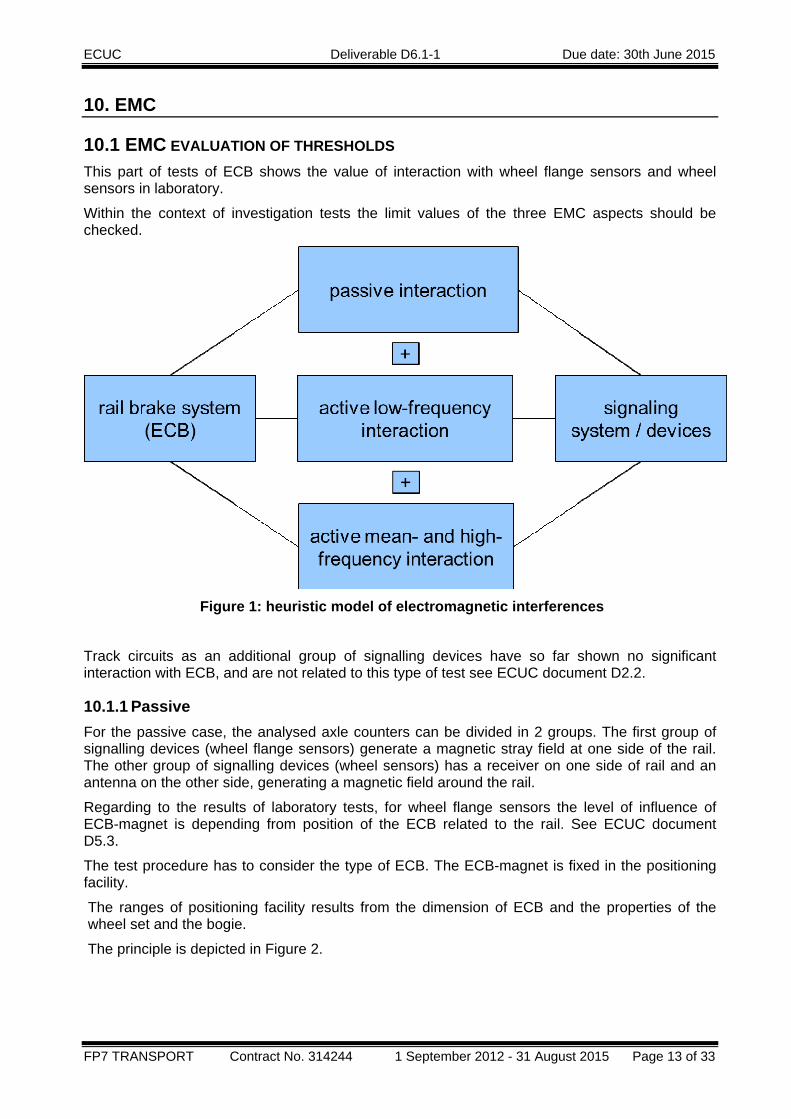
10.1 EMC EVALUATION OF THRESHOLDS This part of tests of ECB shows the value of interaction with wheel flange sensors and wheel sensors in laboratory.
Within the context of investigation tests the limit values of the three EMC aspects should be checked.
Figure 1: heuristic model of electromagnetic interferences
Track circuits as an additional group of signalling devices have so far shown no significant interaction with ECB, and are not related to this type of test see ECUC document D2.2.
10.1.1 Passive For the passive case, the analysed axle counters can be divided in 2 groups. The first group of signalling devices (wheel flange sensors) generate a magnetic stray field at one side of the rail. The other group of signalling devices (wheel sensors) has a receiver on one side of rail and an antenna on the other side, generating a magnetic field around the rail.
Regarding to the results of laboratory tests, for wheel flange sensors the level of influence of ECB-magnet is depending from position of the ECB related to the rail. See ECUC document D5.3.
The test procedure has to consider the type of ECB. The ECB-magnet is fixed in the positioning facility.
The ranges of positioning facility results from the dimension of ECB and the properties of the wheel set and the bogie.
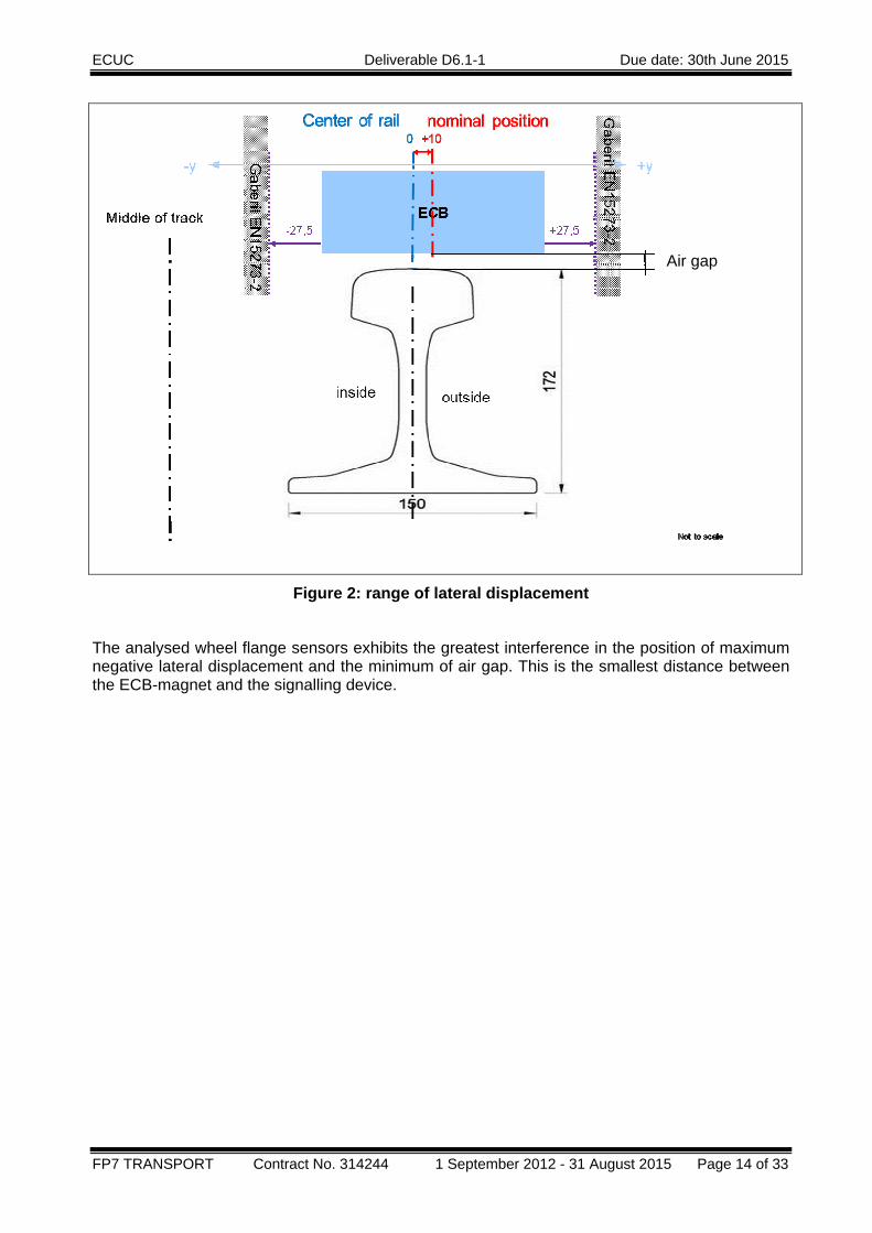
The principle is depicted in Figure 2.
ECUC Deliverable D6.1-1 Due date: 30th June 2015
FP7 TRANSPORT Contract No. 314244 1 September 2012 - 31 August 2015 Page 14 of 33
Figure 2: range of lateral displacement
The analysed wheel flange sensors exhibits the greatest interference in the position of maximum negative lateral displacement and the minimum of air gap. This is the smallest distance between the ECB-magnet and the signalling device.
Air gap
ECUC Deliverable D6.1-1 Due date: 30th June 2015
FP7 TRANSPORT Contract No. 314244 1 September 2012 - 31 August 2015 Page 15 of 33
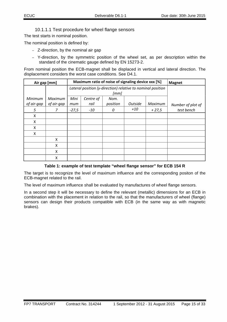
10.1.1.1 Test procedure for wheel flange sensors The test starts in nominal position.
The nominal position is defined by:
– Z-direction, by the nominal air gap
– Y-direction, by the symmetric position of the wheel set, as per description within the standard of the cinematic gauge defined by EN 15273-2.
From nominal position the ECB-magnet shall be displaced in vertical and lateral direction. The displacement considers the worst case conditions. See D4.1.
Air gap [mm] Maximum ratio of noise of signaling device xxx [%] Magnet
Minimum of air‐gap
Maximum of air‐gap
Lateral position (y‐direction) relative to nominal position [mm]
Number of plot of test bench
Minimum
Centre of rail
Nom. position
Outside Maximum
5 7 ‐27,5 ‐10 0 +10 + 27,5 X X X X X X X X
Table 1: example of test template “wheel flange sensor” for ECB 154 R The target is to recognize the level of maximum influence and the corresponding positon of the ECB-magnet related to the rail.
The level of maximum influence shall be evaluated by manufactures of wheel flange sensors.
In a second step it will be necessary to define the relevant (metallic) dimensions for an ECB in combination with the placement in relation to the rail, so that the manufacturers of wheel (flange) sensors can design their products compatible with ECB (in the same way as with magnetic brakes).
ECUC Deliverable D6.1-1 Due date: 30th June 2015
FP7 TRANSPORT Contract No. 314244 1 September 2012 - 31 August 2015 Page 16 of 33
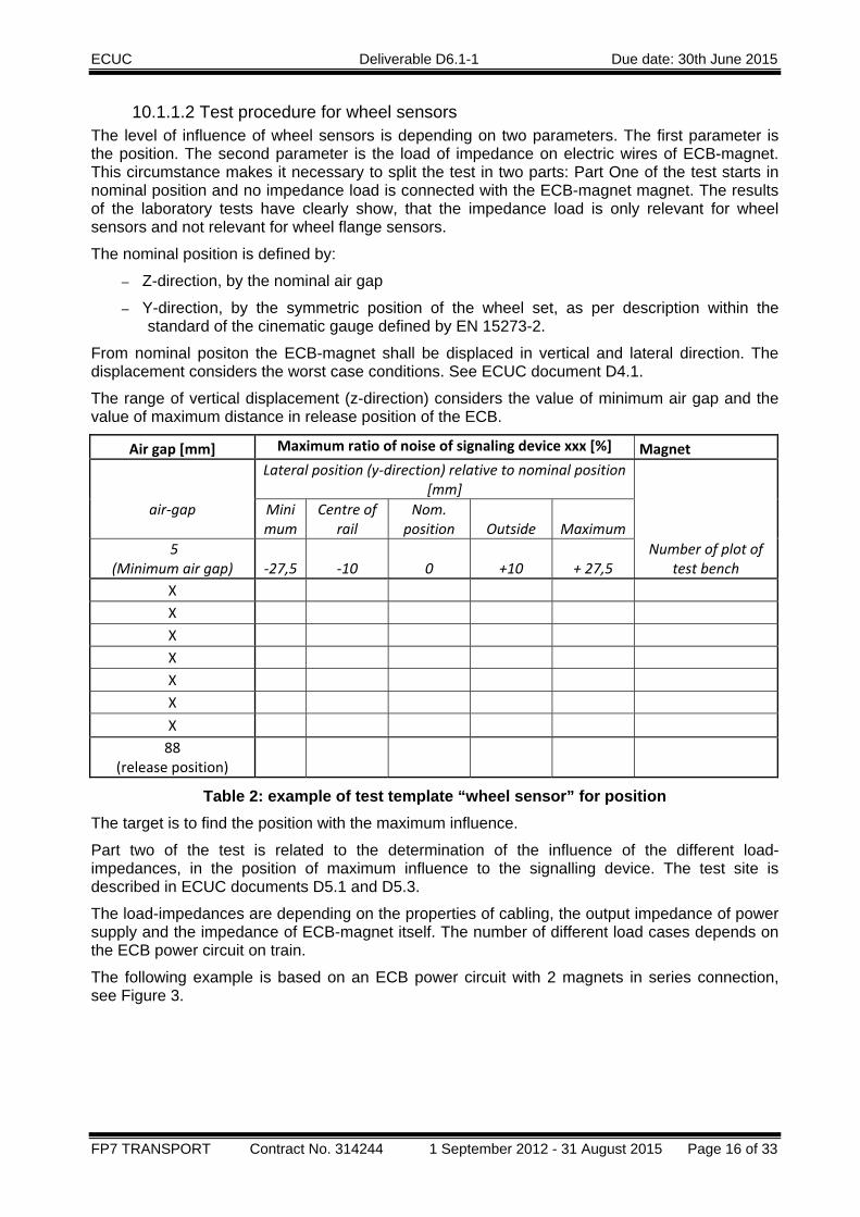
10.1.1.2 Test procedure for wheel sensors The level of influence of wheel sensors is depending on two parameters. The first parameter is the position. The second parameter is the load of impedance on electric wires of ECB-magnet. This circumstance makes it necessary to split the test in two parts: Part One of the test starts in nominal position and no impedance load is connected with the ECB-magnet magnet. The results of the laboratory tests have clearly show, that the impedance load is only relevant for wheel sensors and not relevant for wheel flange sensors.
The nominal position is defined by:
– Z-direction, by the nominal air gap
– Y-direction, by the symmetric position of the wheel set, as per description within the standard of the cinematic gauge defined by EN 15273-2.
From nominal positon the ECB-magnet shall be displaced in vertical and lateral direction. The displacement considers the worst case conditions. See ECUC document D4.1.
The range of vertical displacement (z-direction) considers the value of minimum air gap and the value of maximum distance in release position of the ECB.
Air gap [mm] Maximum ratio of noise of signaling device xxx [%] Magnet
air‐gap
Lateral position (y‐direction) relative to nominal position [mm]
Number of plot of test bench
Minimum
Centre of rail
Nom. position
Outside Maximum
5 (Minimum air gap) ‐27,5 ‐10 0
+10 + 27,5
X X X X X X X 88
(release position)
Table 2: example of test template “wheel sensor” for position The target is to find the position with the maximum influence.
Part two of the test is related to the determination of the influence of the different load-impedances, in the position of maximum influence to the signalling device. The test site is described in ECUC documents D5.1 and D5.3.
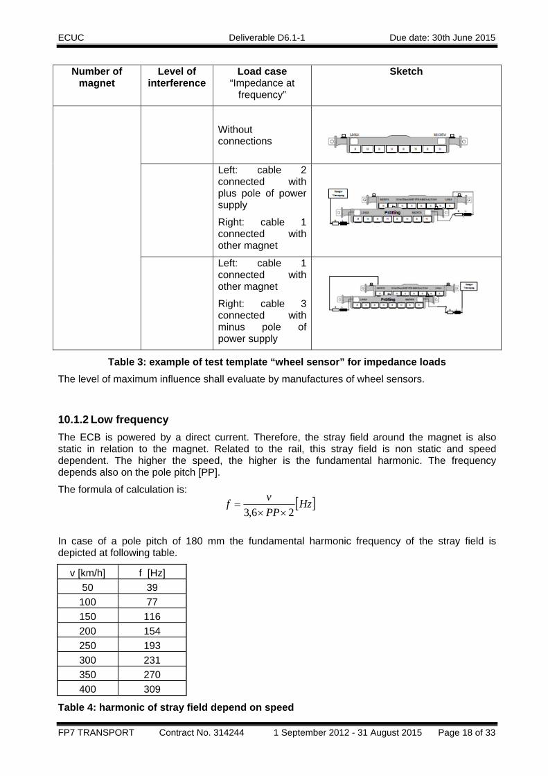
The load-impedances are depending on the properties of cabling, the output impedance of power supply and the impedance of ECB-magnet itself. The number of different load cases depends on the ECB power circuit on train.
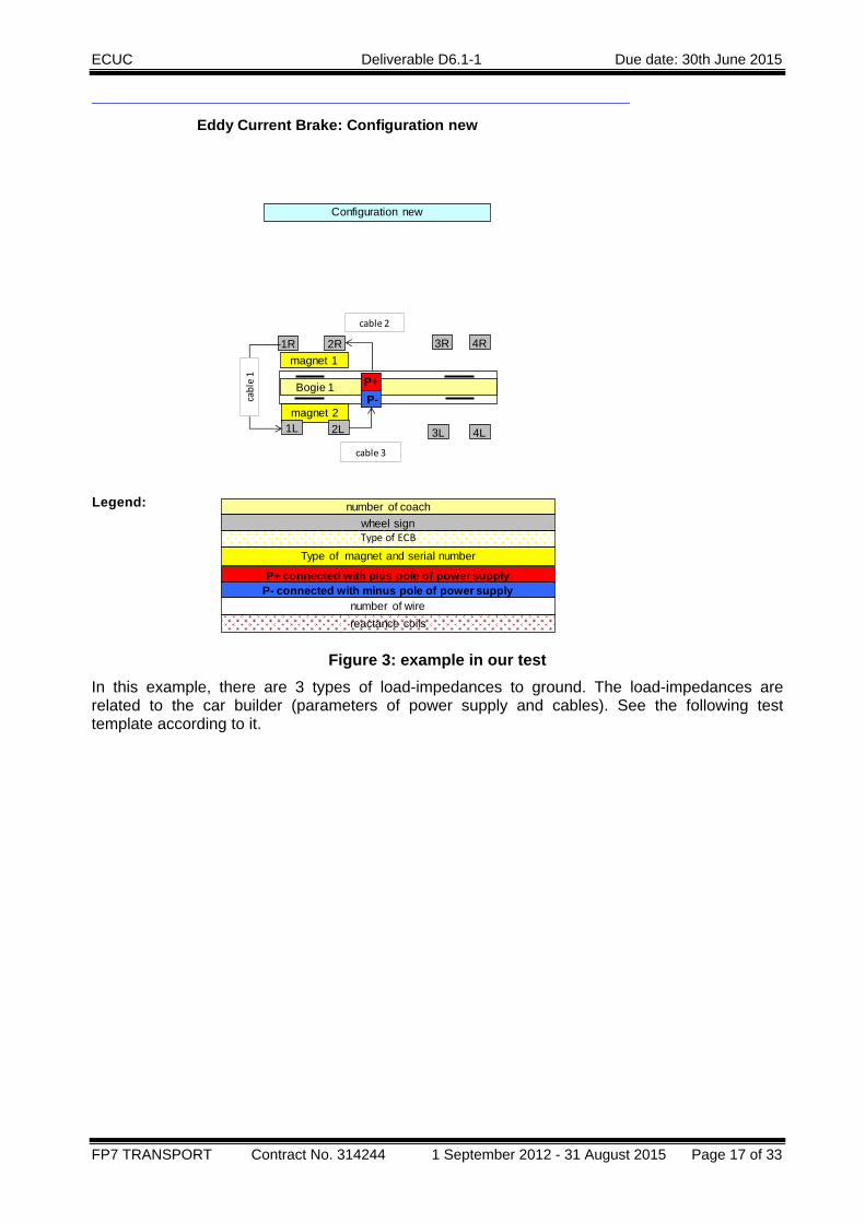
The following example is based on an ECB power circuit with 2 magnets in series connection, see Figure 3.
ECUC Deliverable D6.1-1 Due date: 30th June 2015
FP7 TRANSPORT Contract No. 314244 1 September 2012 - 31 August 2015 Page 17 of 33
Eddy Current Brake: Configuration new
Legend:
Configuration new
Bogie 1
magnet 1
magnet 2
2R1R 4R3R
4L3L2L1L
cable 1
cable 2
P+P-
P+ connected with plus pole of power supply
number of coachwheel sign
Type of magnet and serial number
P- connected with minus pole of power supplynumber of wire
Type of ECB
reactance coils
cable 3
Figure 3: example in our test
In this example, there are 3 types of load-impedances to ground. The load-impedances are related to the car builder (parameters of power supply and cables). See the following test template according to it.
ECUC Deliverable D6.1-1 Due date: 30th June 2015
FP7 TRANSPORT Contract No. 314244 1 September 2012 - 31 August 2015 Page 18 of 33
Number of magnet
Level of interference
Load case “Impedance at
frequency”
Sketch
Without connections
Left: cable 2 connected with plus pole of power supply
Right: cable 1 connected with other magnet
Left: cable 1 connected with other magnet
Right: cable 3 connected with minus pole of power supply
Table 3: example of test template “wheel sensor” for impedance loads The level of maximum influence shall evaluate by manufactures of wheel sensors.
10.1.2 Low frequency The ECB is powered by a direct current. Therefore, the stray field around the magnet is also static in relation to the magnet. Related to the rail, this stray field is non static and speed dependent. The higher the speed, the higher is the fundamental harmonic. The frequency depends also on the pole pitch [PP].
The formula of calculation is:
In case of a pole pitch of 180 mm the fundamental harmonic frequency of the stray field is depicted at following table.
v [km/h] f [Hz]50 39
100 77 150 116 200 154 250 193 300 231 350 270 400 309
Table 4: harmonic of stray field depend on speed
[ ]HzPPvf
26,3 ××=
ECUC Deliverable D6.1-1 Due date: 30th June 2015
FP7 TRANSPORT Contract No. 314244 1 September 2012 - 31 August 2015 Page 19 of 33
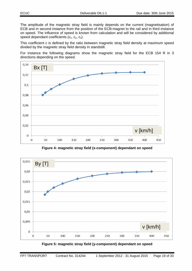
The amplitude of the magnetic stray field is mainly depends on the current (magnetisation) of ECB and in second instance from the position of the ECB-magnet to the rail and in third instance on speed. The influence of speed is known from calculation and will be considered by additional speed dependant coefficients (cx, cy, cz).
This coefficient c is defined by the ratio between magnetic stray field density at maximum speed divided by the magnetic stray field density in standstill.
For instance the following diagrams show the magnetic stray field for the ECB 154 R in 3 directions depending on the speed.
Figure 4: magnetic stray field (x-component) dependant on speed
Figure 5: magnetic stray field (y-component) dependant on speed
By [T]
Bx [T]
v [km/h]
v [km/h]
ECUC Deliverable D6.1-1 Due date: 30th June 2015
FP7 TRANSPORT Contract No. 314244 1 September 2012 - 31 August 2015 Page 20 of 33
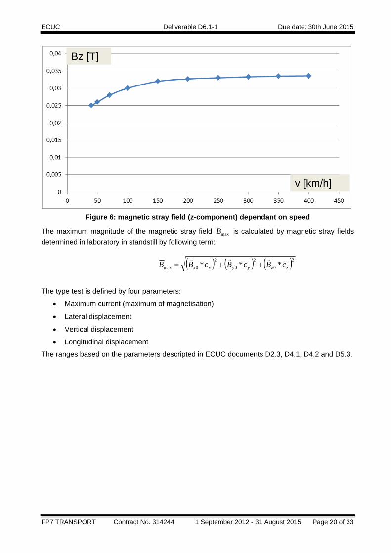
Figure 6: magnetic stray field (z-component) dependant on speed
The maximum magnitude of the magnetic stray field maxB is calculated by magnetic stray fields determined in laboratory in standstill by following term:
The type test is defined by four parameters:
• Maximum current (maximum of magnetisation)
• Lateral displacement
• Vertical displacement
• Longitudinal displacement
The ranges based on the parameters descripted in ECUC documents D2.3, D4.1, D4.2 and D5.3.
Bz [T]
v [km/h]
( ) ( ) ( )202
02
0max *** zzyyxx cBcBcBBrrr
++=
ECUC Deliverable D6.1-1 Due date: 30th June 2015
FP7 TRANSPORT Contract No. 314244 1 September 2012 - 31 August 2015 Page 21 of 33
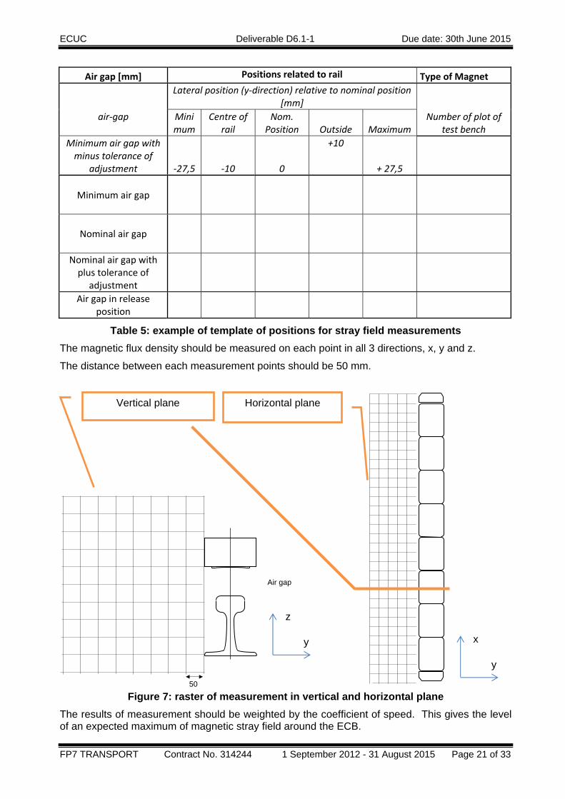
Air gap [mm] Positions related to rail Type of Magnet
air‐gap
Lateral position (y‐direction) relative to nominal position [mm]
Number of plot of test bench
Minimum
Centre of rail
Nom. Position
Outside Maximum
Minimum air gap with minus tolerance of
adjustment ‐27,5 ‐10 0
+10
+ 27,5
Minimum air gap
Nominal air gap
Nominal air gap with plus tolerance of
adjustment
Air gap in release
position
Table 5: example of template of positions for stray field measurements The magnetic flux density should be measured on each point in all 3 directions, x, y and z.
The distance between each measurement points should be 50 mm.
Figure 7: raster of measurement in vertical and horizontal plane The results of measurement should be weighted by the coefficient of speed. This gives the level of an expected maximum of magnetic stray field around the ECB.
50
Air gap
z
y x
y
Vertical plane Horizontal plane

ECUC Deliverable D6.1-1 Due date: 30th June 2015
FP7 TRANSPORT Contract No. 314244 1 September 2012 - 31 August 2015 Page 22 of 33
The level of maximum of magnetic stray field density and the range of harmonics shall be evaluated by manufacturers of signalling devices.
10.1.3 High frequency High frequency magnetic stray fields are generated by the power supply system. Therefore is it necessary to carry these tests out in a laboratory depending of the realisation of the power supply system of a train there may be an influence of the traction unit on the ECB power supply -> in this case a further (final) test with the whole train could be necessary.
Obviously these lab tests can only be considered as investigation tests. As the EMC depend on the electric supply part of the traction equipment and of the physical installation of the cabling, type tests to be carried out with the complete train are mandatory for the acceptance.
Depend on type of signalling device the test site could be a configuration of a pair of poles and a signal generator or a complete system - including the power supply, the chopper, main switch, cables, ECB and rails. The harmonics should be measured with a magnetic noise receiver in the position specified by TS50238-3 or the TSI CCS interface document.
The ECB shall be placed in nominal lateral position. The air gap (position in vertical direction) is varying in range of braking position and release position. See also ECUC document 2.3 table 7.
Air gap [mm] Nominal position of ECB related to rail Type of Magnet
air‐gap
Current (magnetization) of ECB
Number of plot of test bench
Main switch off
0 A
Main switch on
0 A
Minimum‐Service 15 A
Service brake 50 A
Emergency brake 95A
Minimum air gap with minus tolerance of
adjustment
Minimum air gap
Nominal air gap
Nominal air gap with plus tolerance of
adjustment
Air gap in release
position
Table 6: example of template of positions for high frequency stray field measurements The results of measurement shall be evaluated by the thresholds according TS50238-3 or of the frequency management defined by the TSI CCS interface document.
ECUC Deliverable D6.1-1 Due date: 30th June 2015
FP7 TRANSPORT Contract No. 314244 1 September 2012 - 31 August 2015 Page 23 of 33
11. INTERFACES This section describes the Interaction of the brake with its “environment”. The Interfaces are organised in two parts: The first describes the interaction with single components of the train and the second one lists the correlation between brake and infrastructure.
The most obvious interface is between train and brake, because the train needs this brake.
11.1 INTERFACES WITH THE TRAIN
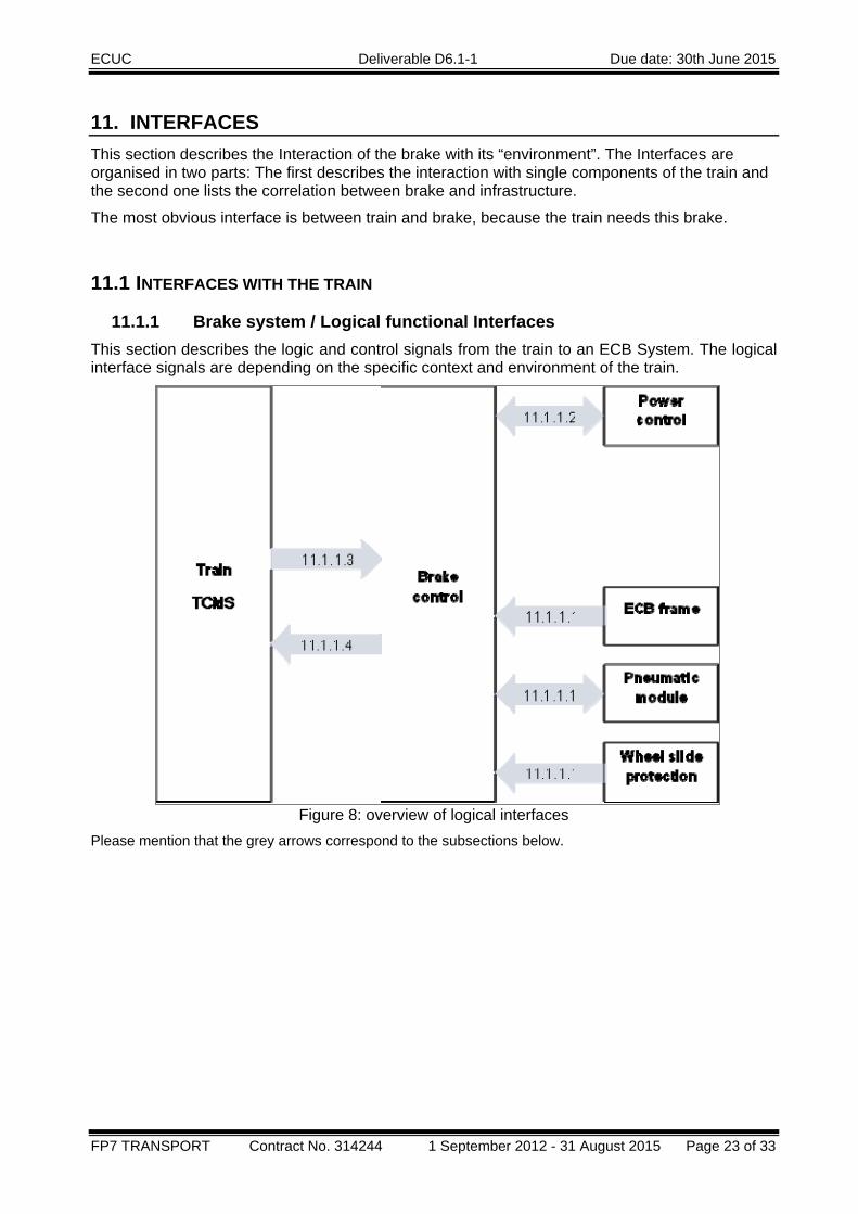
11.1.1 Brake system / Logical functional Interfaces This section describes the logic and control signals from the train to an ECB System. The logical interface signals are depending on the specific context and environment of the train.
Figure 8: overview of logical interfaces Please mention that the grey arrows correspond to the subsections below.
ECUC Deliverable D6.1-1 Due date: 30th June 2015
FP7 TRANSPORT Contract No. 314244 1 September 2012 - 31 August 2015 Page 24 of 33
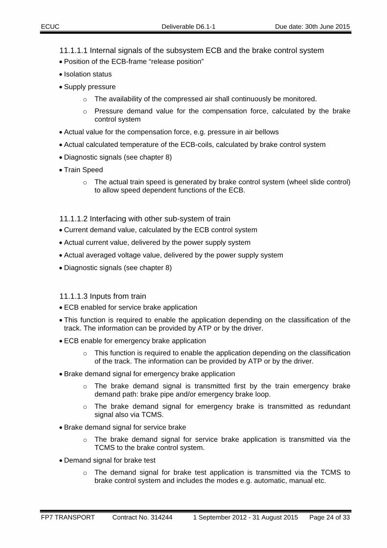
11.1.1.1 Internal signals of the subsystem ECB and the brake control system • Position of the ECB-frame “release position”
• Isolation status
• Supply pressure
o The availability of the compressed air shall continuously be monitored.
o Pressure demand value for the compensation force, calculated by the brake control system
• Actual value for the compensation force, e.g. pressure in air bellows
• Actual calculated temperature of the ECB-coils, calculated by brake control system
• Diagnostic signals (see chapter 8)
• Train Speed
o The actual train speed is generated by brake control system (wheel slide control) to allow speed dependent functions of the ECB.
11.1.1.2 Interfacing with other sub-system of train • Current demand value, calculated by the ECB control system
• Actual current value, delivered by the power supply system
• Actual averaged voltage value, delivered by the power supply system
• Diagnostic signals (see chapter 8)
11.1.1.3 Inputs from train • ECB enabled for service brake application
• This function is required to enable the application depending on the classification of the track. The information can be provided by ATP or by the driver.
• ECB enable for emergency brake application
o This function is required to enable the application depending on the classification of the track. The information can be provided by ATP or by the driver.
• Brake demand signal for emergency brake application
o The brake demand signal is transmitted first by the train emergency brake demand path: brake pipe and/or emergency brake loop.
o The brake demand signal for emergency brake is transmitted as redundant signal also via TCMS.
• Brake demand signal for service brake
o The brake demand signal for service brake application is transmitted via the TCMS to the brake control system.
• Demand signal for brake test
o The demand signal for brake test application is transmitted via the TCMS to brake control system and includes the modes e.g. automatic, manual etc.

ECUC Deliverable D6.1-1 Due date: 30th June 2015
FP7 TRANSPORT Contract No. 314244 1 September 2012 - 31 August 2015 Page 25 of 33
11.1.1.4 Outputs to train • The status of ECB availability shall be indicated to the driver, see chapter 8 “Monitoring
and Diagnostics”.
o Complete or partial isolation of any braking units either voluntarily or automatically shall immediately and permanently be reported to the driver.
• Undue activation of ECB (lowering or/and powering on) shall be detected and reported to the driver.
11.1.2 Pneumatic Interfaces The pneumatic interface of the ECB frame is the air supply to the bellows supporting and lifting the ECB frame. The piping to supply the bellows with compressed air is part of the bogie design. The pipe network must have sufficient capacity to feed the bellows and to ensure quick venting to lower the bellows rapidly in case of emergency brake applications.
In order to discharge the bellows quickly and to lower the frame into working position, an additional venting device is recommended close to the bogie. This device can be realized as a quick discharge valve, which vents the attached devices with large capacity in case of a rapid pressure drop on the supply side. The ECB frame must reach the lower working position within 2 sec from the initiation of an emergency brake command.
The maximum supply pressure for the bellows is the pressure that is required to keep the ECB frame in the upper working position. A minimum pressure of 6 bar is sufficient to keep the frame in the upper position. Maximum acceptable pressure is 10 bar.
Note: such minimum pressure means that the supply can only be from the main reservoir pipe (max brake pipe pressure is 5 bar).
The air consumption that is required for one operating cycle can be calculated from the following operating phases:
- Lowering of the frame at the beginning of the application (complete venting)
- Supporting the frame in working position (feeding with controlled pressure)
- Compensation of attractive forces (feeding with controlled pressure)
- Lowering the frame at the end of the brake application (complete venting)
- Lifting the frame (feeding with max. pressure 6 bar)
The total air consumption in normal condition per bogie for this operating cycle shall be calculated.
In according to EN15734 three consecutive applications shall be considered for the sizing of the local reservoir.
For this purpose, also the main air reservoirs can be taken into account.
ECUC Deliverable D6.1-1 Due date: 30th June 2015
FP7 TRANSPORT Contract No. 314244 1 September 2012 - 31 August 2015 Page 26 of 33
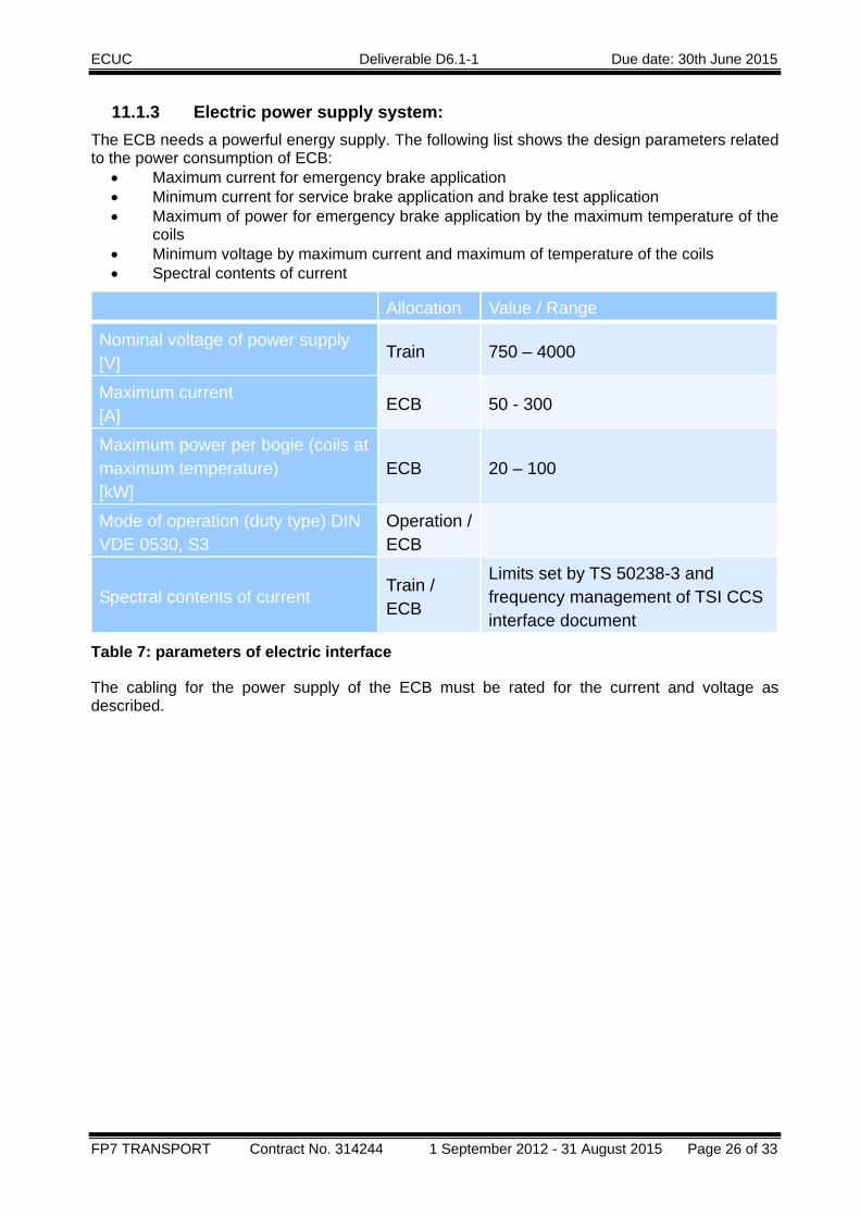
11.1.3 Electric power supply system: The ECB needs a powerful energy supply. The following list shows the design parameters related to the power consumption of ECB:
• Maximum current for emergency brake application • Minimum current for service brake application and brake test application • Maximum of power for emergency brake application by the maximum temperature of the
coils • Minimum voltage by maximum current and maximum of temperature of the coils • Spectral contents of current
Allocation Value / Range
Nominal voltage of power supply [V] Train 750 – 4000 Maximum current [A] ECB 50 - 300 Maximum power per bogie (coils at maximum temperature) [kW]
ECB 20 – 100
Mode of operation (duty type) DIN VDE 0530, S3
Operation / ECB
Spectral contents of current Train / ECB
Limits set by TS 50238-3 and frequency management of TSI CCS interface document
Table 7: parameters of electric interface
The cabling for the power supply of the ECB must be rated for the current and voltage as described.
ECUC Deliverable D6.1-1 Due date: 30th June 2015
FP7 TRANSPORT Contract No. 314244 1 September 2012 - 31 August 2015 Page 27 of 33
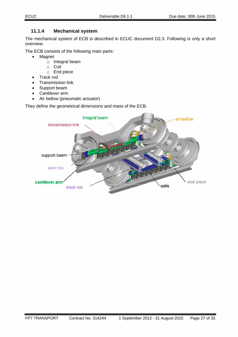
11.1.4 Mechanical system The mechanical system of ECB is described in ECUC document D2.3. Following is only a short overview.
The ECB consists of the following main parts: • Magnet
o Integral beam o Coil o End piece
• Track rod • Transmission link • Support beam • Cantilever arm • Air bellow (pneumatic actuator)
They define the geometrical dimensions and mass of the ECB.

ECUC Deliverable D6.1-1 Due date: 30th June 2015
FP7 TRANSPORT Contract No. 314244 1 September 2012 - 31 August 2015 Page 28 of 33
The mechanical interfaces of ECB are related to the bogie and wheel set.
In release positon the ECB is fixed to the bogie frame and has no contact to the wheelsets. The ECB is attached to the bogie at four mounting points by brackets. The holder is a part of the actuation. The “air bellow” actuation raises the ECB in the high position (release position).
The brackets are transfer vertical and horizontal (lateral and longitudinal) forces.
The transmission links do not transfer forces in release position.
Figure 9: relevant interfaces in release position
This interface can be described by
holder / suspension Transmission link
Material X X
Position X X
Drill pattern X X
Screws X X
Loads Vertical, longitudinal, lateral
Free
Table 8: interfaces in release position
holder
Transmission link
ECUC Deliverable D6.1-1 Due date: 30th June 2015
FP7 TRANSPORT Contract No. 314244 1 September 2012 - 31 August 2015 Page 29 of 33
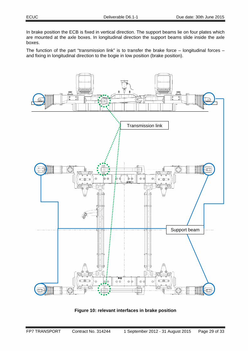
In brake position the ECB is fixed in vertical direction. The support beams lie on four plates which are mounted at the axle boxes. In longitudinal direction the support beams slide inside the axle boxes.
The function of the part “transmission link” is to transfer the brake force – longitudinal forces – and fixing in longitudinal direction to the bogie in low position (brake position).
Figure 10: relevant interfaces in brake position
Transmission link
Support beam
ECUC Deliverable D6.1-1 Due date: 30th June 2015
FP7 TRANSPORT Contract No. 314244 1 September 2012 - 31 August 2015 Page 30 of 33
Support beam Transmission link
Material X X
Position X X
Drill pattern - X
Screws - X
Loads Vertical, lateral
related to axle box, wheel set, bogie
Longitudinal
related bogie
Table 9: interface in brake position The vertical and lateral loads are considered to design of the bogie, wheel-sets and axle boxes.
Related standards are:
• EN 13103-1 Railway applications – Wheel-sets and bogies - Part 1: Design guide for axles with external journals,
• EN12080 axle boxes, bearings.
11.2 INTERFACES INFRASTRUCTURE:
11.2.1 Signaling devices The principle of ECB based on magnetic fields. The brake force depends on level of magnetisation in air gap between ECB – magnet and rail. Around this configuration stray fields are built and the rail is saturated. In laboratory it is possible to carry out tests with worst case conditions. The levels of interaction are helpful for the evaluation of compatibility with signalling devices.
The register of infrastructure should list compatible and approved signalling devices or gives general information about the possibility of use the ECB on certain line.
Especially the level of high frequency stray fields shall be evaluated according TS50238-3 and the requirements defined in the TSI CCS interface document.
ECUC Deliverable D6.1-1 Due date: 30th June 2015
FP7 TRANSPORT Contract No. 314244 1 September 2012 - 31 August 2015 Page 31 of 33
11.2.2 Rail The track stability is defined by the averaged rail temperature. The level of allowed averaged rail temperature is depended on type of track. For instance on one hand the unballasted tracks and on other hand the conventional ballasted tracks. The difference of allowed average rail temperature is significant. (This parameter should be an item of D6.3)
• The physical effect is descripted in ECUC document D3.3.
• The increase of rail temperature is depended on brake force by ECB.
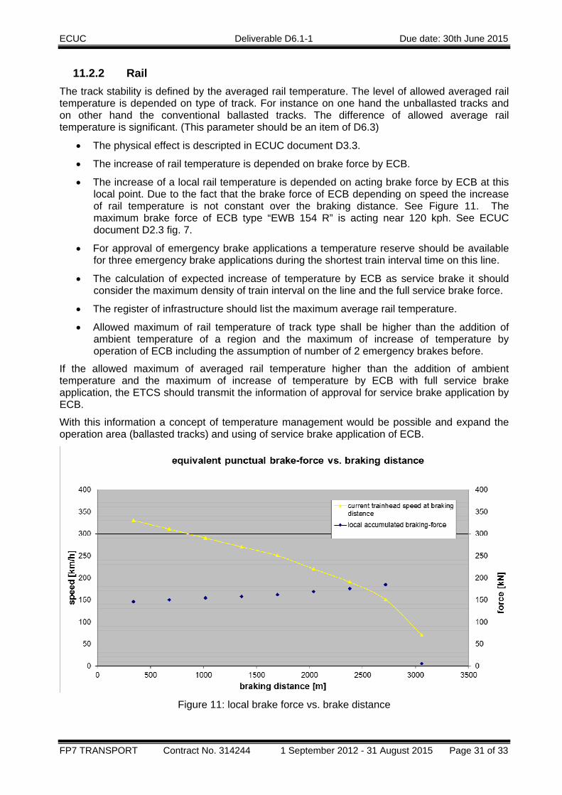
• The increase of a local rail temperature is depended on acting brake force by ECB at this local point. Due to the fact that the brake force of ECB depending on speed the increase of rail temperature is not constant over the braking distance. See Figure 11. The maximum brake force of ECB type “EWB 154 R” is acting near 120 kph. See ECUC document D2.3 fig. 7.
• For approval of emergency brake applications a temperature reserve should be available for three emergency brake applications during the shortest train interval time on this line.
• The calculation of expected increase of temperature by ECB as service brake it should consider the maximum density of train interval on the line and the full service brake force.
• The register of infrastructure should list the maximum average rail temperature.
• Allowed maximum of rail temperature of track type shall be higher than the addition of ambient temperature of a region and the maximum of increase of temperature by operation of ECB including the assumption of number of 2 emergency brakes before.
If the allowed maximum of averaged rail temperature higher than the addition of ambient temperature and the maximum of increase of temperature by ECB with full service brake application, the ETCS should transmit the information of approval for service brake application by ECB.
With this information a concept of temperature management would be possible and expand the operation area (ballasted tracks) and using of service brake application of ECB.
Figure 11: local brake force vs. brake distance
ECUC Deliverable D6.1-1 Due date: 30th June 2015
FP7 TRANSPORT Contract No. 314244 1 September 2012 - 31 August 2015 Page 32 of 33
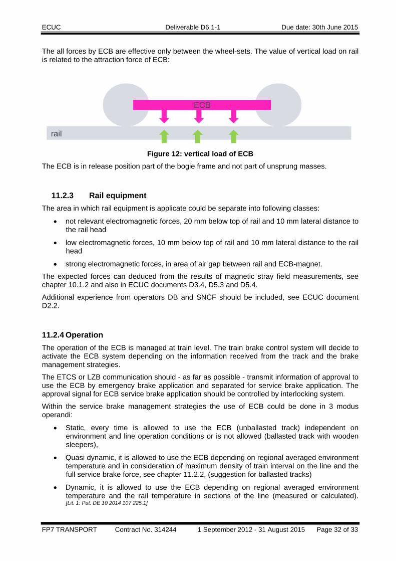
The all forces by ECB are effective only between the wheel-sets. The value of vertical load on rail is related to the attraction force of ECB:
Figure 12: vertical load of ECB
The ECB is in release position part of the bogie frame and not part of unsprung masses.
11.2.3 Rail equipment The area in which rail equipment is applicate could be separate into following classes:
• not relevant electromagnetic forces, 20 mm below top of rail and 10 mm lateral distance to the rail head
• low electromagnetic forces, 10 mm below top of rail and 10 mm lateral distance to the rail head
• strong electromagnetic forces, in area of air gap between rail and ECB-magnet.
The expected forces can deduced from the results of magnetic stray field measurements, see chapter 10.1.2 and also in ECUC documents D3.4, D5.3 and D5.4.
Additional experience from operators DB and SNCF should be included, see ECUC document D2.2.
11.2.4 Operation The operation of the ECB is managed at train level. The train brake control system will decide to activate the ECB system depending on the information received from the track and the brake management strategies.
The ETCS or LZB communication should - as far as possible - transmit information of approval to use the ECB by emergency brake application and separated for service brake application. The approval signal for ECB service brake application should be controlled by interlocking system.
Within the service brake management strategies the use of ECB could be done in 3 modus operandi:
• Static, every time is allowed to use the ECB (unballasted track) independent on environment and line operation conditions or is not allowed (ballasted track with wooden sleepers),
• Quasi dynamic, it is allowed to use the ECB depending on regional averaged environment temperature and in consideration of maximum density of train interval on the line and the full service brake force, see chapter 11.2.2, (suggestion for ballasted tracks)
• Dynamic, it is allowed to use the ECB depending on regional averaged environment temperature and the rail temperature in sections of the line (measured or calculated). [Lit. 1: Pat. DE 10 2014 107 225.1]
ECUC Deliverable D6.1-1 Due date: 30th June 2015
FP7 TRANSPORT Contract No. 314244 1 September 2012 - 31 August 2015 Page 33 of 33
12. HANDLING DURING MAINTENANCE The content and the intervals of maintenance work are listed in maintenance document.
The most important maintenance work is the adjustment of the air gap. The requirement on workshop is a straight and plane track with no interrupted rails and nominal track gauge. Before starting the work it is necessary to check the symmetric position of wheel-set in the track.
The interval of adjusting the air gap depends on the wear of wheels. This is a project specific parameter and should be defined by vehicle manufacturers. The experience in service of ECB shows, that the tolerance on the air gap requires an adjustment is made each time the wheel diameter reduction due to wear as been more than 2 mm.
The other important note is that the ECB is a high voltage device. A high pressure cleaning of electric parts (e.g. coils) is forbidden.
Conventional maintenance works (typical railway) are defined in a project specific maintenance plan (e.g. grease, visual check of mechanical damage) which includes preventive and corrective works depending on operation time.
Other typical ECB maintenance work is not necessary.