ECE544: Communication Networks-II, Spring 2011 D. Raychaudhuri Lecture 5 Includes teaching materials...
74
ECE544: Communication Networks-II, Spring 2011 D. Raychaudhuri Lecture 5 Includes teaching materials from L. Peterson, J. Kurose, K. Almeroth
-
date post
21-Dec-2015 -
Category
Documents
-
view
215 -
download
1
Transcript of ECE544: Communication Networks-II, Spring 2011 D. Raychaudhuri Lecture 5 Includes teaching materials...
ECE544: Communication Networks-II, Spring 2011
D. RaychaudhuriLecture 5
Includes teaching materials from L. Peterson, J. Kurose, K. Almeroth
Today’s Lecture• Scalable Addressing
• Sub-netting• Super-netting (CIDR)• Route Aggregation Examples
• BGP• Global Internet routing• BGP protocol outline

Internetwork
Phy layer Header
Ethernet Header
IPHeader
TCP/UDPHeader
DataPayload
Ethernet Trailer
Phy layer Trailer
H 3H 2
H5
H 8 H 9
H 7
H10
H 6H 1
H 4
Ethernet Switching
IP Routing
R
ETH FDDI
IP
Phy Phy
H
IP
ETH
TCP
Appl.
Phy
S
ETH ETH
ETH Bridging
PhyPhy
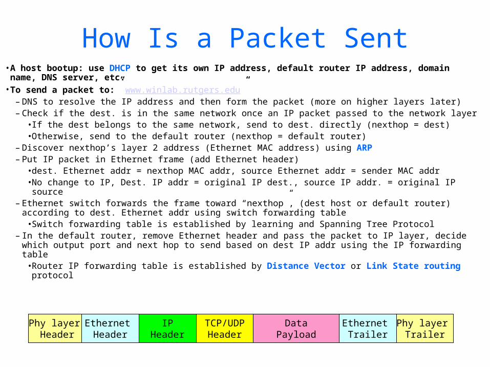
How Is a Packet Sent•A host bootup: use DHCP to get its own IP address, default router IP address, domain name, DNS server, etc.
•To send a packet to:” www.winlab.rutgers.edu”– DNS to resolve the IP address and then form the packet (more on higher layers later)– Check if the dest. is in the same network once an IP packet passed to the network layer
•If the dest belongs to the same network, send to dest. directly (nexthop = dest)•Otherwise, send to the default router (nexthop = default router)
– Discover nexthop’s layer 2 address (Ethernet MAC address) using ARP– Put IP packet in Ethernet frame (add Ethernet header)
•dest. Ethernet addr = nexthop MAC addr, source Ethernet addr = sender MAC addr•No change to IP, Dest. IP addr = original IP dest., source IP addr. = original IP source
– Ethernet switch forwards the frame toward “nexthop”, (dest host or default router) according to dest. Ethernet addr using switch forwarding table•Switch forwarding table is established by learning and Spanning Tree Protocol
– In the default router, remove Ethernet header and pass the packet to IP layer, decide which output port and next hop to send based on dest IP addr using the IP forwarding table•Router IP forwarding table is established by Distance Vector or Link State routing protocol
Phy layer Header
Ethernet Header
IPHeader
TCP/UDPHeader
DataPayload
Ethernet Trailer
Phy layer Trailer
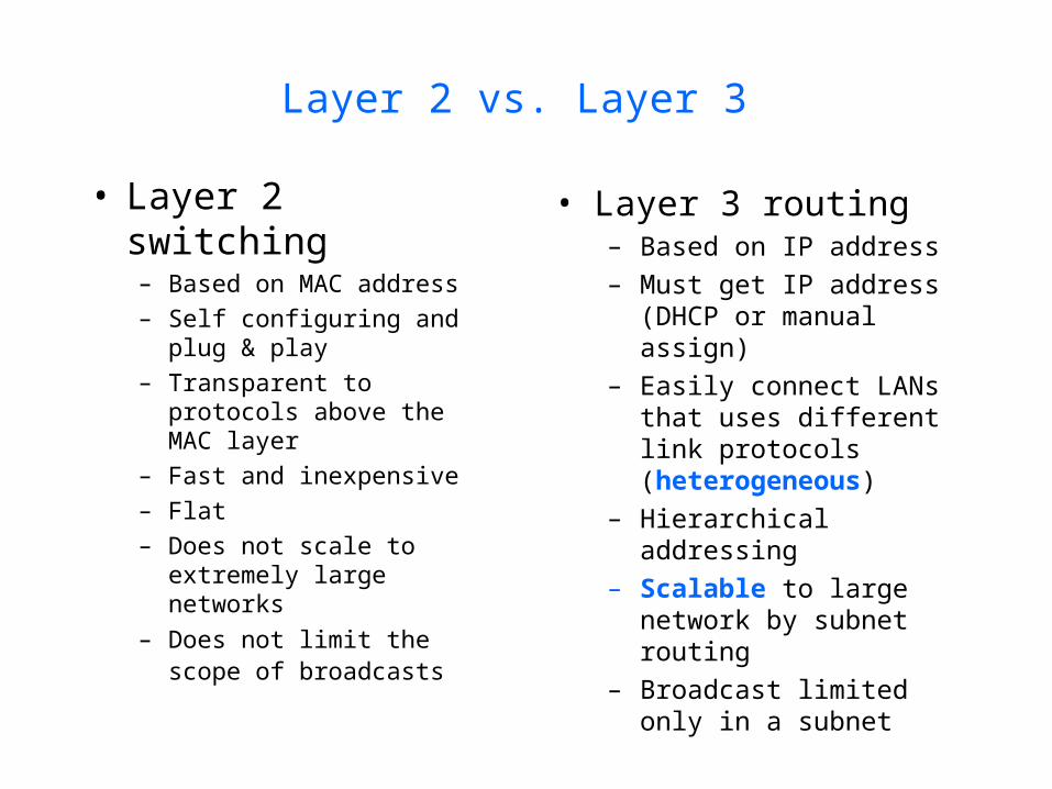
Layer 2 vs. Layer 3
• Layer 2 switching– Based on MAC address– Self configuring and
plug & play– Transparent to
protocols above the MAC layer
– Fast and inexpensive– Flat– Does not scale to
extremely large networks
– Does not limit the scope of broadcasts
• Layer 3 routing– Based on IP address– Must get IP address
(DHCP or manual assign)
– Easily connect LANs that uses different link protocols (heterogeneous)
– Hierarchical addressing
– Scalable to large network by subnet routing
– Broadcast limited only in a subnet

Distance Vector vs. Link State
Distance Vector• A node exchanges
routing info only with its directly connected neighbors
• Exchanged routing info: distance to all nodes in its routing table (everything this node has learned)
• Route computation: Distributed Bellman-Ford
Link State• A node floods its
link-state advertisement to all the nodes in the network
• Exchanged routing info: the state of the links to its directly connected links
• Route computation: Dijkstra’s algorithm
Scalable IP Routing
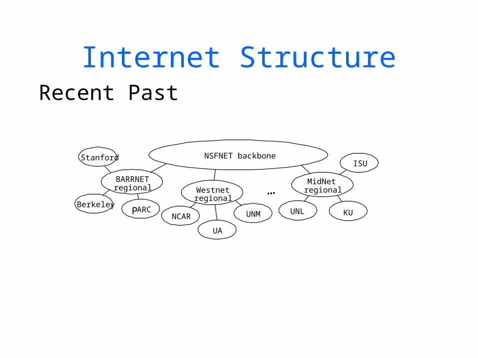
Internet StructureRecent Past
NSFNET backboneStanford
BARRNETregional
BerkeleyPARC
NCAR
UA
UNM
Westnetregional
UNL KU
ISU
MidNetregional…
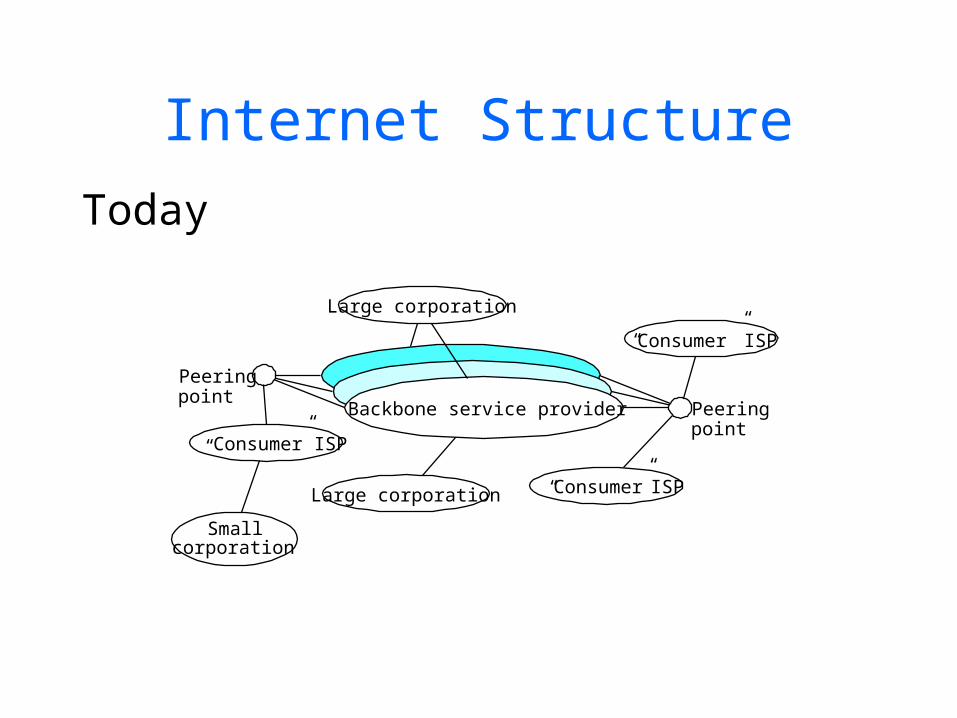
Internet StructureToday
Backbone service provider
Peeringpoint
Peeringpoint
Large corporation
Large corporation
Smallcorporation
“Consumer ” ISP
“Consumer” ISP
“ Consumer” ISP
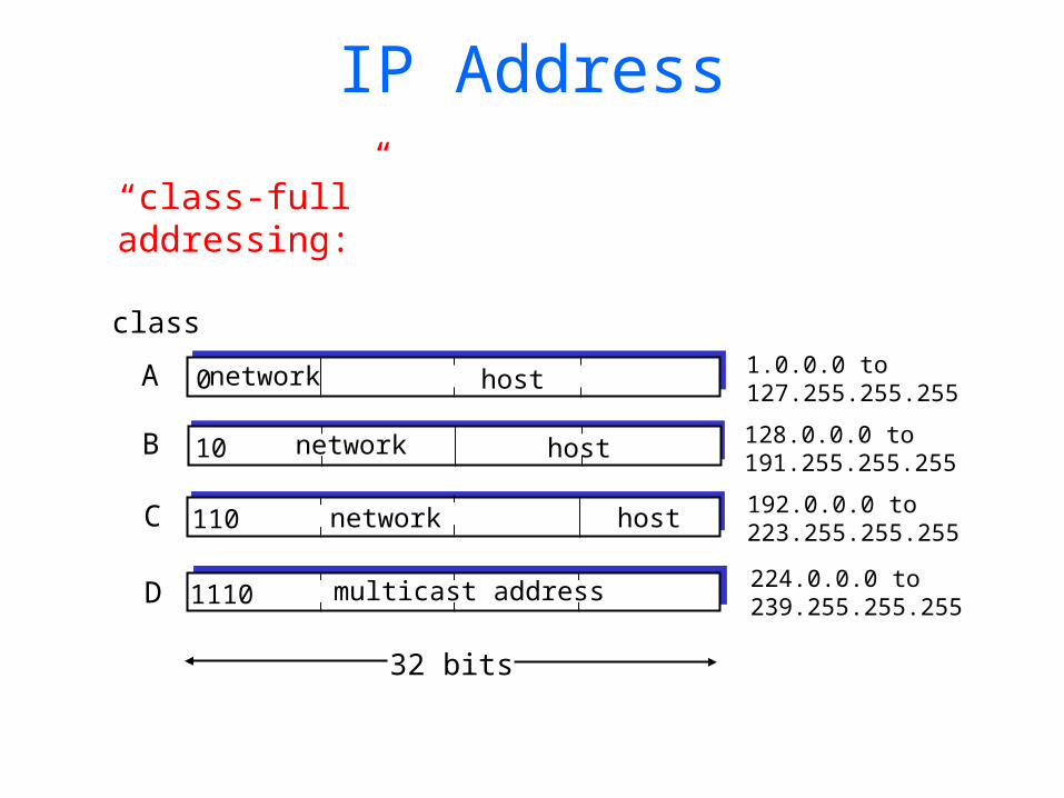
IP Address
0network host
10 network host
110 network host
1110 multicast address
A
B
C
D
class1.0.0.0 to127.255.255.255
128.0.0.0 to191.255.255.255
192.0.0.0 to223.255.255.255
224.0.0.0 to239.255.255.255
32 bits
“class-full” addressing:
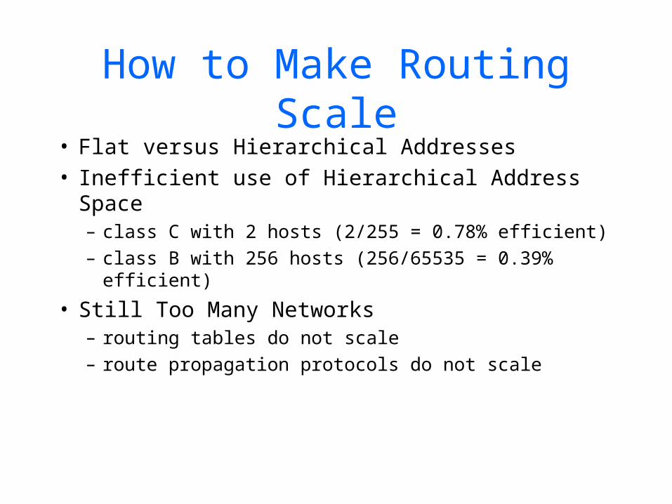
How to Make Routing Scale
• Flat versus Hierarchical Addresses• Inefficient use of Hierarchical Address Space
– class C with 2 hosts (2/255 = 0.78% efficient)– class B with 256 hosts (256/65535 = 0.39%
efficient)
• Still Too Many Networks– routing tables do not scale– route propagation protocols do not scale
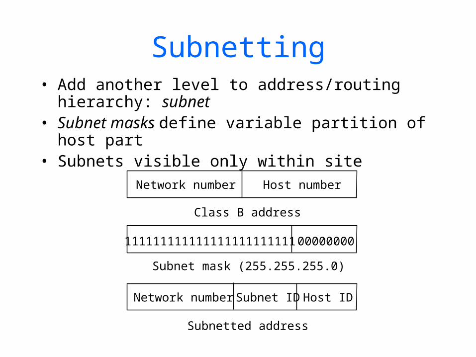
Subnetting• Add another level to address/routing
hierarchy: subnet• Subnet masks define variable partition of host
part• Subnets visible only within site
Network number Host number
Class B address
Subnet mask (255.255.255.0)
Subnetted address
111111111111111111111111 00000000
Network number Host IDSubnet ID
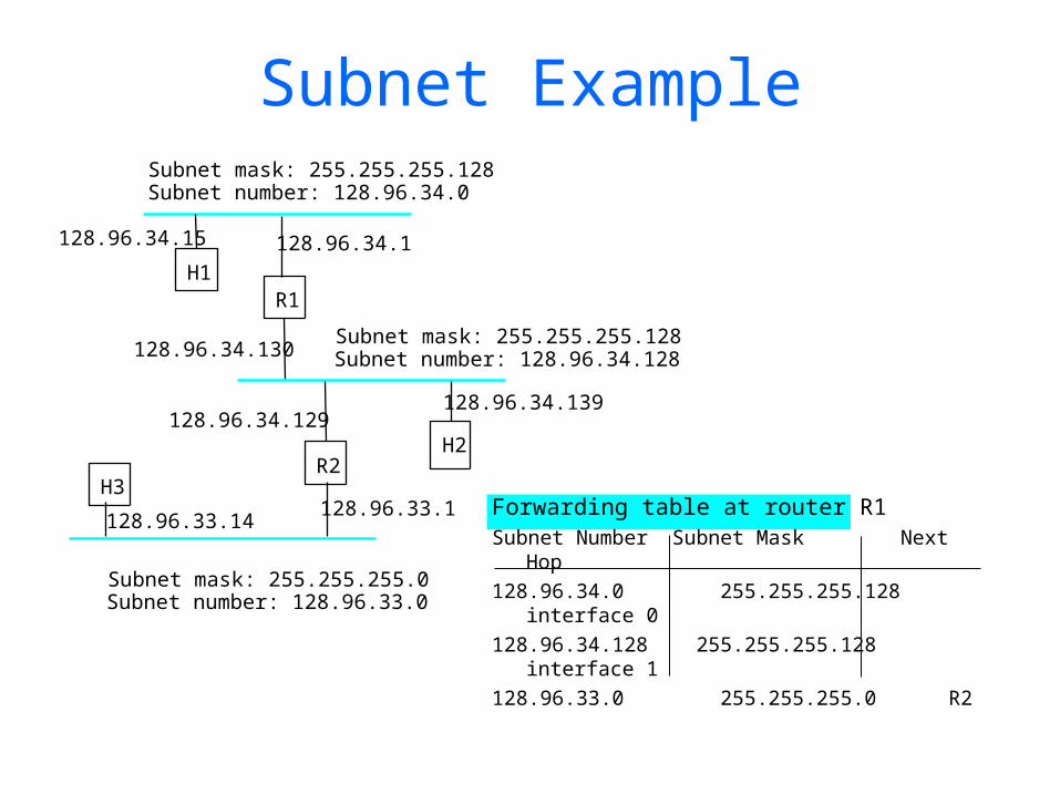
Subnet Example
Forwarding table at router R1Subnet Number Subnet Mask Next
Hop128.96.34.0 255.255.255.128
interface 0128.96.34.128 255.255.255.128
interface 1128.96.33.0 255.255.255.0 R2
Subnet mask: 255.255.255.128Subnet number: 128.96.34.0
128.96.34.15 128.96.34.1
H1R1
128.96.34.130Subnet mask: 255.255.255.128Subnet number: 128.96.34.128
128.96.34.129128.96.34.139
R2H2
128.96.33.1128.96.33.14
Subnet mask: 255.255.255.0Subnet number: 128.96.33.0
H3
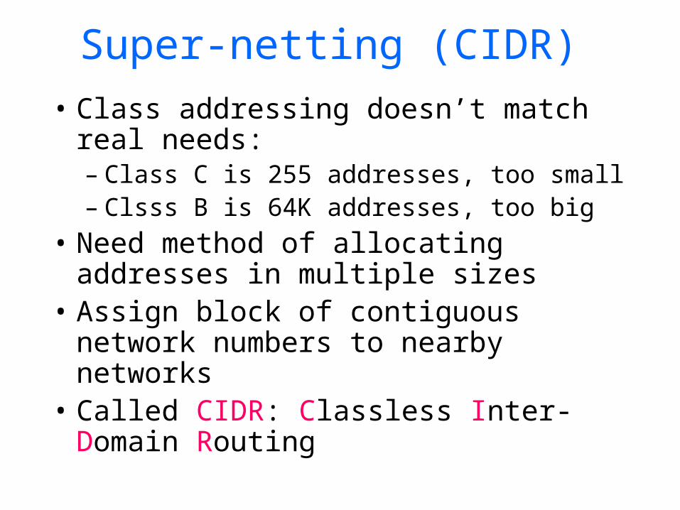
Super-netting (CIDR)• Class addressing doesn’t match real
needs:– Class C is 255 addresses, too small– Clsss B is 64K addresses, too big
• Need method of allocating addresses in multiple sizes
• Assign block of contiguous network numbers to nearby networks
• Called CIDR: Classless Inter-Domain Routing
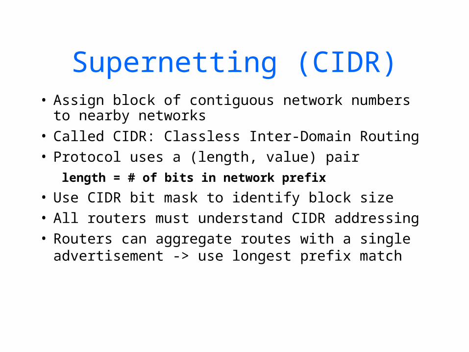
Supernetting (CIDR)• Assign block of contiguous network numbers
to nearby networks• Called CIDR: Classless Inter-Domain Routing• Protocol uses a (length, value) pair length = # of bits in network prefix
• Use CIDR bit mask to identify block size• All routers must understand CIDR addressing• Routers can aggregate routes with a single
advertisement -> use longest prefix match
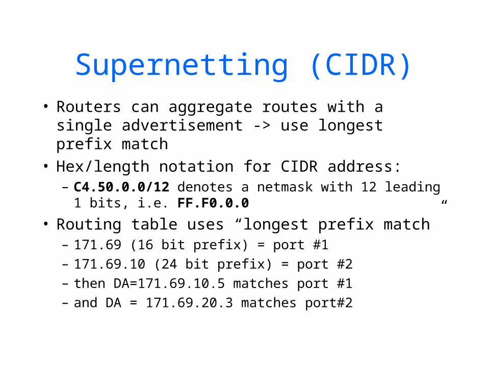
Supernetting (CIDR)• Routers can aggregate routes with a single
advertisement -> use longest prefix match• Hex/length notation for CIDR address:
– C4.50.0.0/12 denotes a netmask with 12 leading 1 bits, i.e. FF.F0.0.0
• Routing table uses “longest prefix match”– 171.69 (16 bit prefix) = port #1– 171.69.10 (24 bit prefix) = port #2– then DA=171.69.10.5 matches port #1– and DA = 171.69.20.3 matches port#2

Classless Inter Domain Routing (CIDR)
Class B:
Class C:
Net ID Host ID
Host IDNet ID
Problem: Class B addresses are running out Solution: Allocate multiple Class C addresses Problem: Random allocation of Class C addresses need multiple routing table entries Solution: Allocate “contiguous” Class C addresses Routing entry: [IP Address of Network and Net Mask]
IP Address: 195.201.3.5 = 11000011 11001001 00000011 00000101Net Mask: 254.0.0.0 = 11111110 00000000 00000000 00000000-----------------------------------------------------------------------------------------Network IP: 194.0.0.0 = 11000010 00000000 00000000 00000000
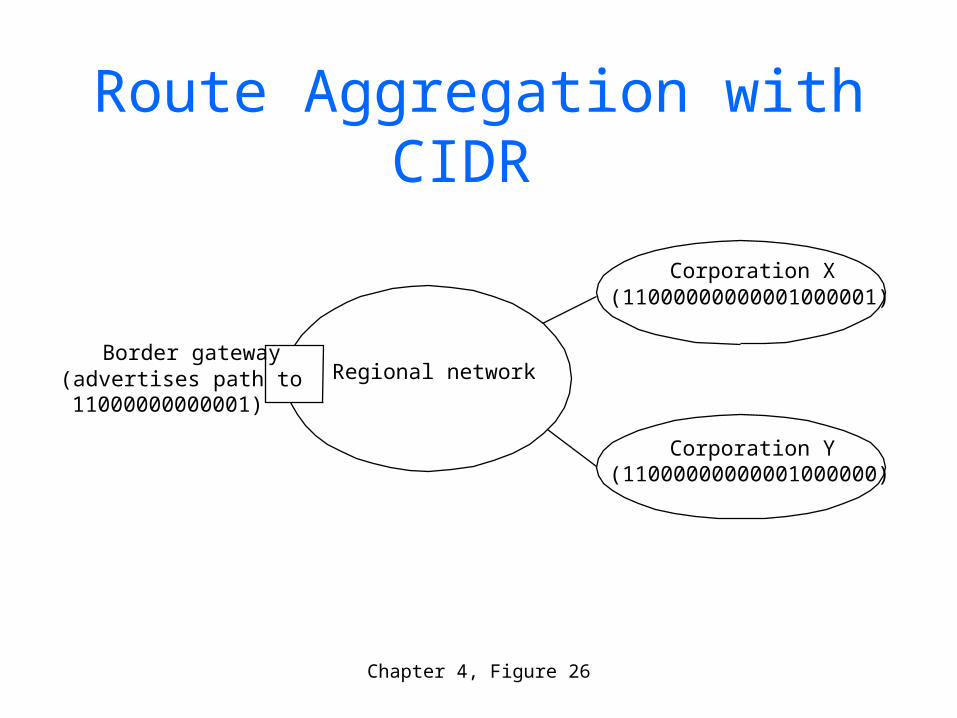
Chapter 4, Figure 26
Border gateway(advertises path to
11000000000001)
Regional network
Corporation X(11000000000001000001)
Corporation Y(11000000000001000000)
Route Aggregation with CIDR
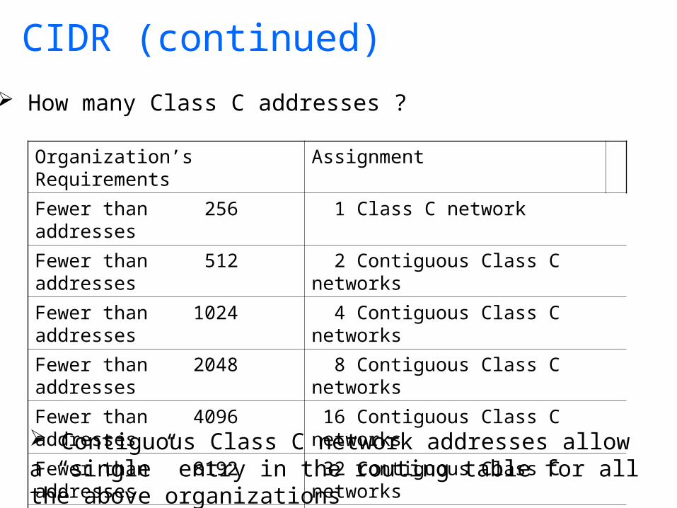
CIDR (continued)
Organization’s Requirements Assignment
Fewer than 256 addresses 1 Class C network
Fewer than 512 addresses 2 Contiguous Class C networks
Fewer than 1024 addresses 4 Contiguous Class C networks
Fewer than 2048 addresses 8 Contiguous Class C networks
Fewer than 4096 addresses 16 Contiguous Class C networks
Fewer than 8192 addresses 32 Contiguous Class C networks
Fewer than 16384 addresses 64 Contiguous Class C networks
How many Class C addresses ?
Contiguous Class C network addresses allow a “single” entry in the routing table for all the above organizations
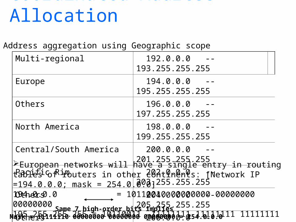
Coordinated Address Allocation
Multi-regional 192.0.0.0 -- 193.255.255.255
Europe 194.0.0.0 -- 195.255.255.255
Others 196.0.0.0 -- 197.255.255.255
North America 198.0.0.0 -- 199.255.255.255
Central/South America 200.0.0.0 -- 201.255.255.255
Pacific Rim 202.0.0.0 -- 203.255.255.255
Others 204.0.0.0 -- 205.255.255.255
Others 206.0.0.0 -- 207.255.255.255
Address aggregation using Geographic scope
European networks will have a single entry in routing tables of routers in other continents: [Network IP =194.0.0.0; mask = 254.0.0.0]194.0.0.0 = 10110010 00000000 00000000 00000000195.255.255.255 = 10110011 11111111 11111111 11111111
Same 7 high-order bits implies Mask = 11111110 00000000 00000000 00000000 = 254.0.0.0
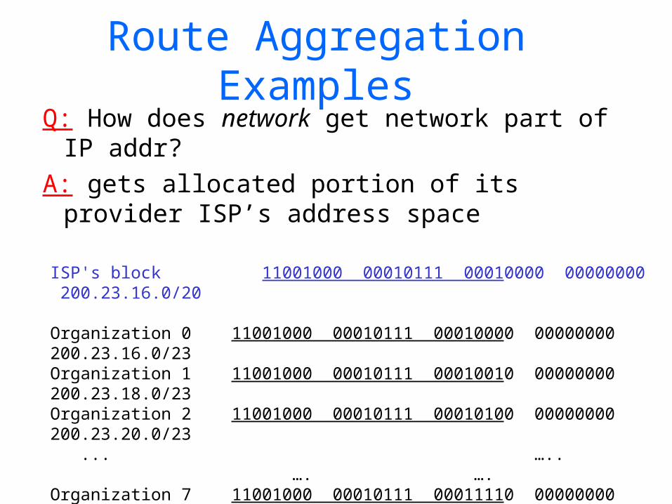
Route Aggregation Examples
Q: How does network get network part of IP addr?
A: gets allocated portion of its provider ISP’s address space
ISP's block 11001000 00010111 00010000 00000000 200.23.16.0/20
Organization 0 11001000 00010111 00010000 00000000 200.23.16.0/23 Organization 1 11001000 00010111 00010010 00000000 200.23.18.0/23 Organization 2 11001000 00010111 00010100 00000000 200.23.20.0/23 ... ….. …. ….
Organization 7 11001000 00010111 00011110 00000000 200.23.30.0/23
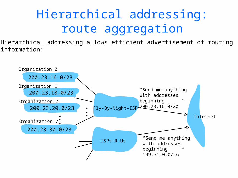
Hierarchical addressing: route aggregation
“Send me anythingwith addresses beginning 200.23.16.0/20”
200.23.16.0/23
200.23.18.0/23
200.23.30.0/23
Fly-By-Night-ISP
Organization 0
Organization 7Internet
Organization 1
ISPs-R-Us“Send me anythingwith addresses beginning 199.31.0.0/16”
200.23.20.0/23Organization 2
...
...
Hierarchical addressing allows efficient advertisement of routing information:
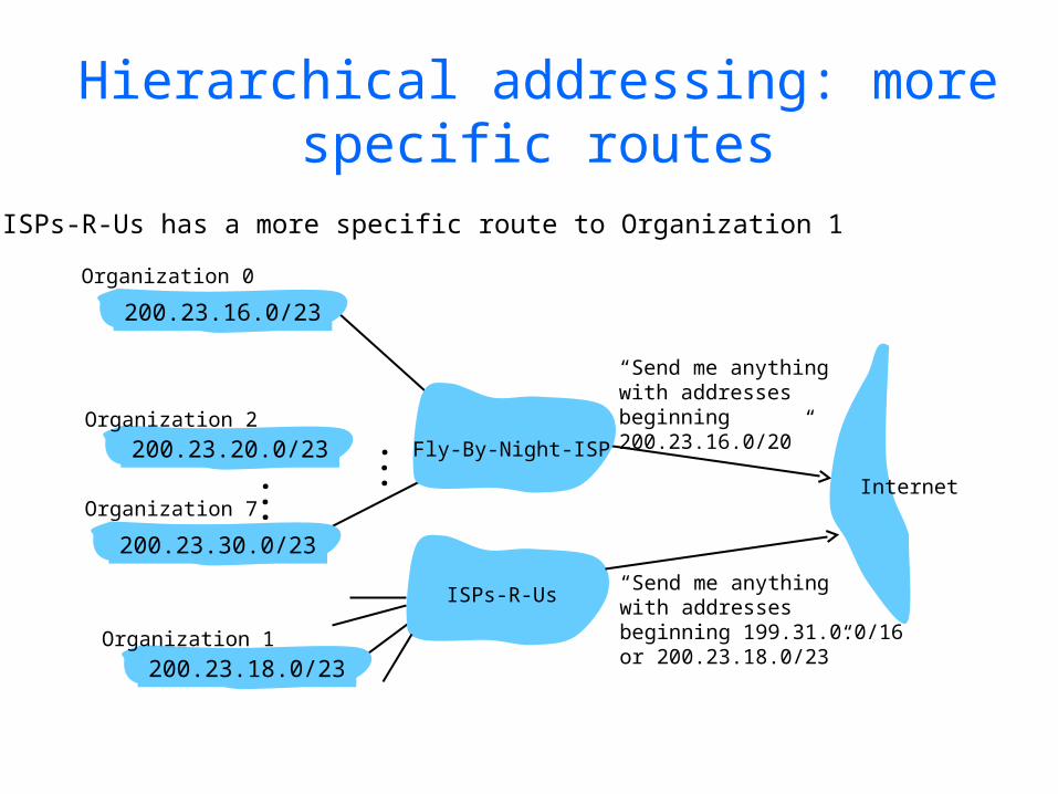
Hierarchical addressing: more specific routes
ISPs-R-Us has a more specific route to Organization 1
“Send me anythingwith addresses beginning 200.23.16.0/20”
200.23.16.0/23
200.23.18.0/23
200.23.30.0/23
Fly-By-Night-ISP
Organization 0
Organization 7Internet
Organization 1
ISPs-R-Us“Send me anythingwith addresses beginning 199.31.0.0/16or 200.23.18.0/23”
200.23.20.0/23Organization 2
...
...
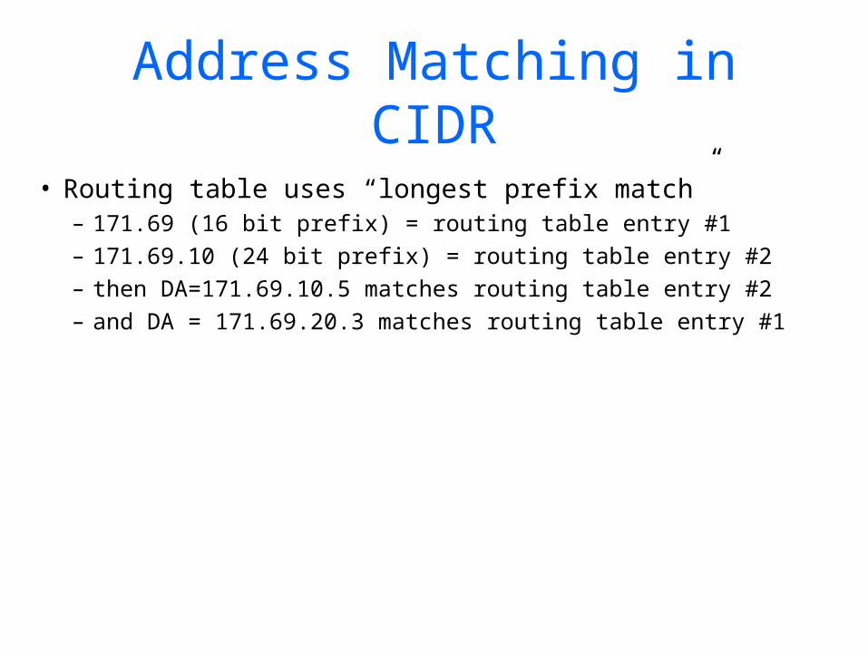
Address Matching in CIDR
• Routing table uses “longest prefix match”– 171.69 (16 bit prefix) = routing table entry #1– 171.69.10 (24 bit prefix) = routing table entry #2– then DA=171.69.10.5 matches routing table entry #2– and DA = 171.69.20.3 matches routing table entry
#1
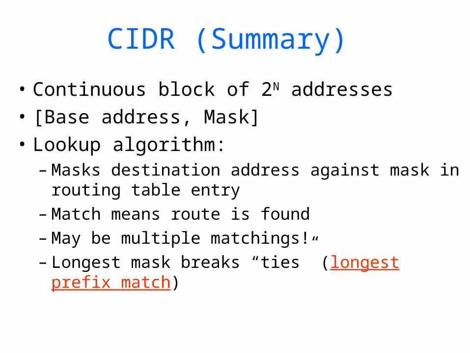
CIDR (Summary)
• Continuous block of 2N addresses• [Base address, Mask]• Lookup algorithm:
– Masks destination address against mask in routing table entry
– Match means route is found – May be multiple matchings! – Longest mask breaks “ties” (longest prefix
match)
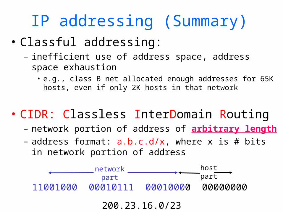
IP addressing (Summary)• Classful addressing:
– inefficient use of address space, address space exhaustion
• e.g., class B net allocated enough addresses for 65K hosts, even if only 2K hosts in that network
• CIDR: Classless InterDomain Routing– network portion of address of arbitrary length– address format: a.b.c.d/x, where x is # bits in
network portion of address
11001000 00010111 00010000 00000000
networkpart
hostpart
200.23.16.0/23

IPv6

IP Version 6• Features
– 128-bit addresses (classless)– multicast– real-time service– authentication and security – autoconfiguration – end-to-end fragmentation– protocol extensions
• Header– 40-byte “base” header– extension headers (fixed order, mostly fixed length)
• fragmentation• source routing• authentication and security• other options
IP ServiceIP Service IPv4 SolutionIPv4 Solution IPv6 SolutionIPv6 Solution
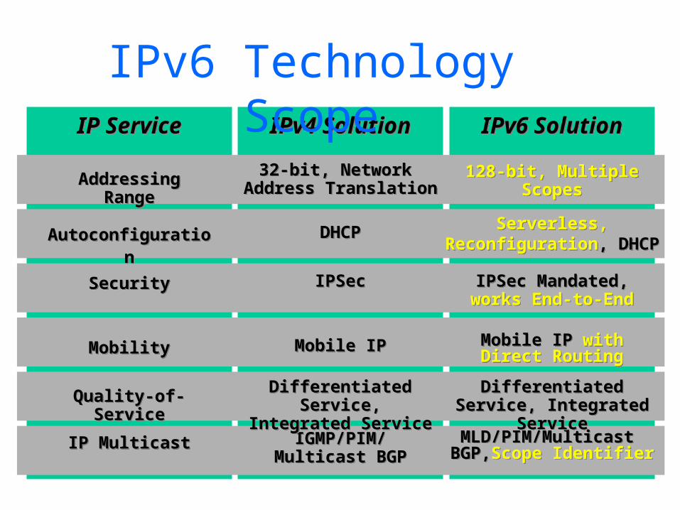
Mobile IP with Direct Routing
Mobile IP with Direct Routing
DHCPDHCP
Mobile IPMobile IP
IGMP/PIM/Multicast BGP
IGMP/PIM/Multicast BGP
IP MulticastIP Multicast MLD/PIM/Multicast BGP,Scope IdentifierMLD/PIM/Multicast
BGP,Scope Identifier
MobilityMobility
AutoconfigurationAutoconfigurationServerless,
Reconfiguration, DHCPServerless,
Reconfiguration, DHCP
IPv6 Technology Scope
32-bit, Network Address Translation
32-bit, Network Address Translation
128-bit, MultipleScopes
128-bit, MultipleScopes
Addressing RangeAddressing Range
Quality-of-ServiceQuality-of-Service Differentiated Service, Integrated Service
Differentiated Service, Integrated Service
Differentiated Service, Integrated Service
Differentiated Service, Integrated Service
SecuritySecurity IPSec Mandated, works End-to-EndIPSec Mandated,
works End-to-EndIPSecIPSec
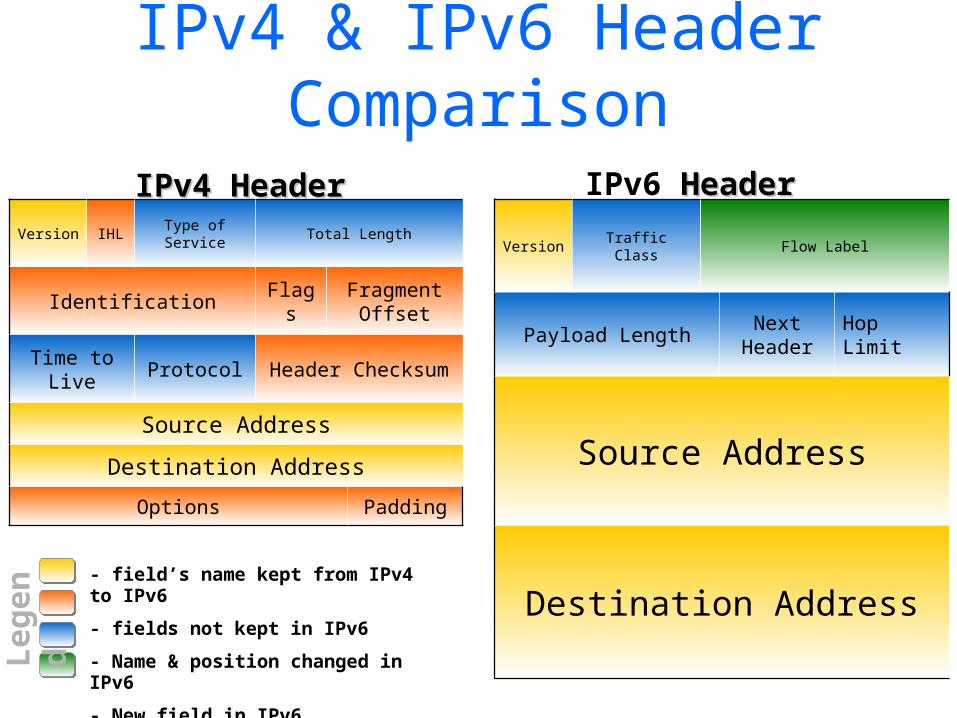
IPv4 & IPv6 Header Comparison
Version IHLType of Service
Total Length
Identification FlagsFragment
Offset
Time to Live
Protocol Header Checksum
Source Address
Destination Address
Options Padding
Version Traffic Class Flow Label
Payload LengthNext
HeaderHop Limit
Source Address
Destination Address
IPv4 HeaderIPv4 Header IPv6 HeaderHeader
- field’s name kept from IPv4 to IPv6
- fields not kept in IPv6
- Name & position changed in IPv6
- New field in IPv6Leg
end
31
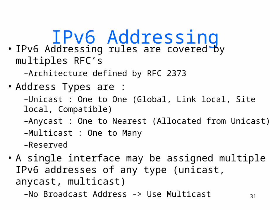
IPv6 Addressing • IPv6 Addressing rules are covered by multiples
RFC’s–Architecture defined by RFC 2373
• Address Types are :–Unicast : One to One (Global, Link local, Site local, Compatible)–Anycast : One to Nearest (Allocated from Unicast)–Multicast : One to Many–Reserved
• A single interface may be assigned multiple IPv6 addresses of any type (unicast, anycast, multicast)
–No Broadcast Address -> Use Multicast
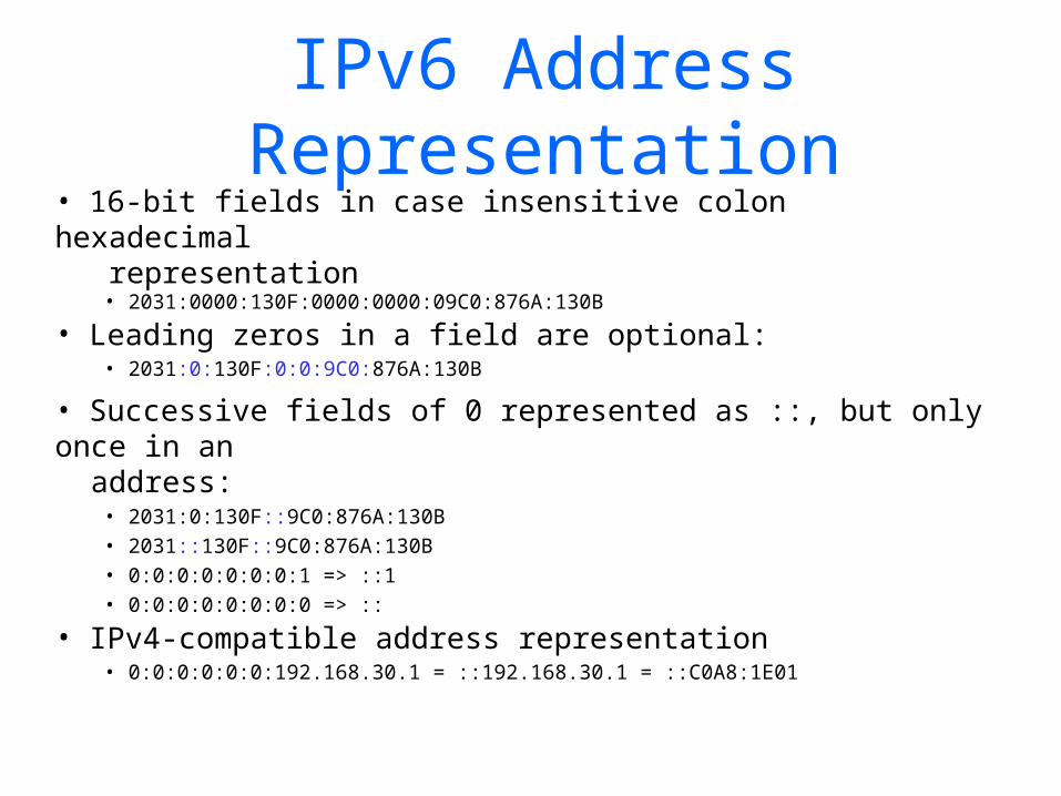
IPv6 Address Representation
• 16-bit fields in case insensitive colon hexadecimal representation
• 2031:0000:130F:0000:0000:09C0:876A:130B
• Leading zeros in a field are optional:• 2031:0:130F:0:0:9C0:876A:130B
• Successive fields of 0 represented as ::, but only once in an address:
• 2031:0:130F::9C0:876A:130B• 2031::130F::9C0:876A:130B• 0:0:0:0:0:0:0:1 => ::1• 0:0:0:0:0:0:0:0 => ::
• IPv4-compatible address representation• 0:0:0:0:0:0:192.168.30.1 = ::192.168.30.1 = ::C0A8:1E01
33
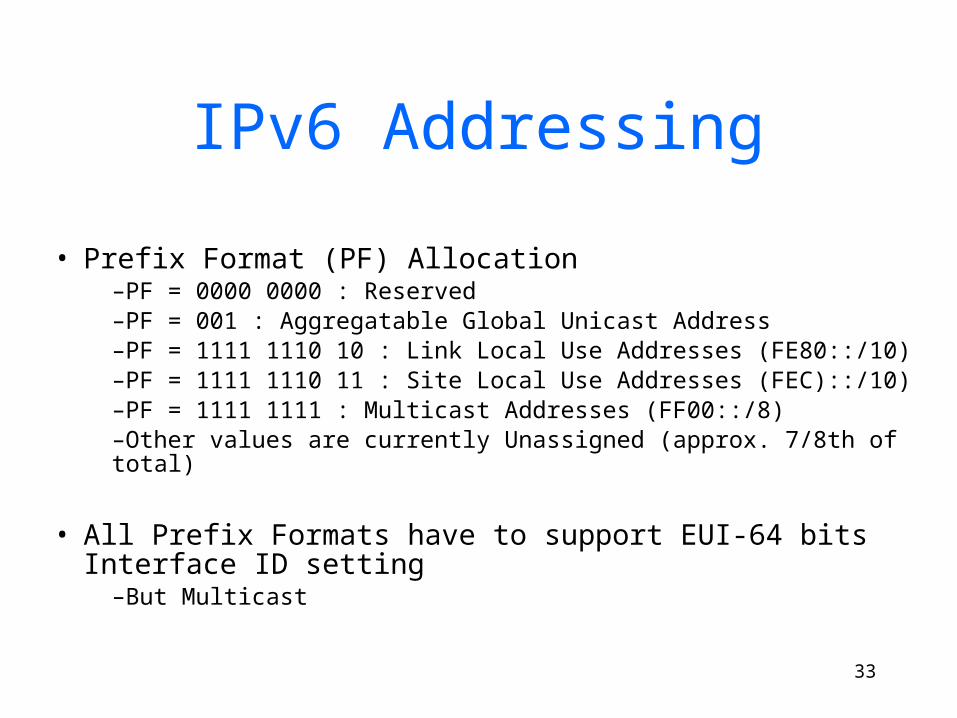
IPv6 Addressing
• Prefix Format (PF) Allocation–PF = 0000 0000 : Reserved–PF = 001 : Aggregatable Global Unicast Address–PF = 1111 1110 10 : Link Local Use Addresses (FE80::/10)–PF = 1111 1110 11 : Site Local Use Addresses (FEC)::/10)–PF = 1111 1111 : Multicast Addresses (FF00::/8)–Other values are currently Unassigned (approx. 7/8th of total)
• All Prefix Formats have to support EUI-64 bits Interface ID setting
–But Multicast

Aggregatable Global Unicast Addresses
• Aggregatable Global Unicast addresses are:–Addresses for generic use of IPv6–Structured as a hierarchy to keep the aggregation
• See draft-ietf-ipngwg-addr-arch-v3-07
Interface IDGlobal Routing Prefix SLA
001
64 bits3 45 bits 16 bits
Provider Site Host

Address Allocation
• The allocation process is under reviewed by the Registries: –IANA allocates 2001::/16 to registries–Each registry gets a /23 prefix from IANA–Formely, all ISP were getting a /35–With the new proposal, Registry allocates a /36 (immediate allocation) or /32 (initial allocation) prefix to an IPv6 ISP–Policy is that an ISP allocates a /48 prefix to each end customer–ftp://ftp.cs.duke.edu/pub/narten/ietf/global-ipv6-assign-2002-04-25.txt
2001 0410
ISP prefix
Site prefix
LAN prefix
/32 /48 /64
Registry
/23
Bootstrap process - RFC2450
Interface ID
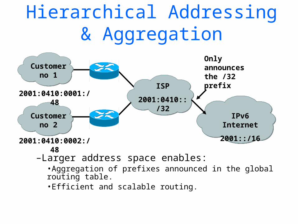
Hierarchical Addressing & Aggregation
–Larger address space enables:•Aggregation of prefixes announced in the global routing table.•Efficient and scalable routing.
ISP
2001:0410::/32
Customerno 2
IPv6 Internet
2001::/16
2001:0410:0002:/48
2001:0410:0001:/48
Customerno 1
Only announces the /32 prefix
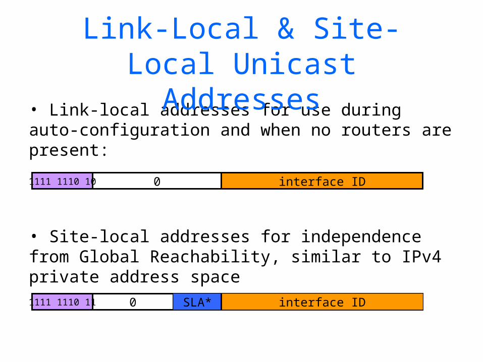
• Link-local addresses for use during auto-configuration and when no routers are present:
• Site-local addresses for independence from Global Reachability, similar to IPv4 private address space
Link-Local & Site-Local Unicast Addresses
1111 1110 10 0 interface ID
1111 1110 11 0 interface IDSLA*

Multicast Addresses (RFC 2375)
• low-order flag indicates permanent / transient group; three other flags reserved
• scope field: 1 - node local–2 - link-local–5 - site-local–8 - organization-local–B - community-local–E - global–(all other values reserved)
4 112 bits8
group IDscopeflags11111111
4
39
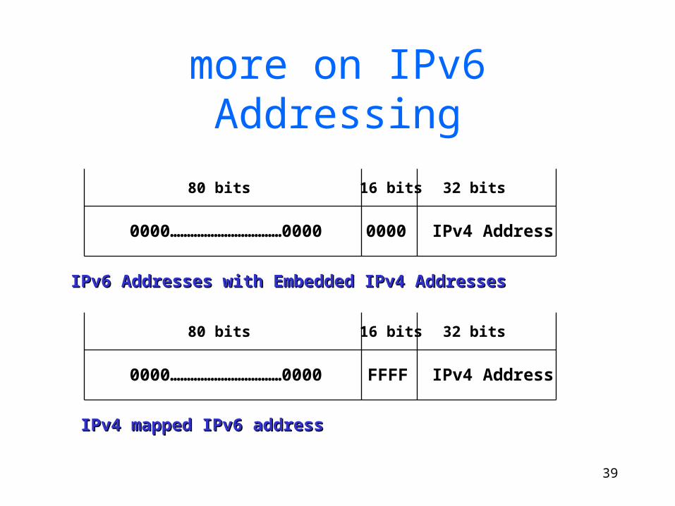
more on IPv6 Addressing
80 bits 32 bits16 bits
IPv4 Address00000000……………………………0000
IPv6 Addresses with Embedded IPv4 AddressesIPv6 Addresses with Embedded IPv4 Addresses
80 bits 32 bits16 bits
IPv4 AddressFFFF0000……………………………0000
IPv4 mapped IPv6 addressIPv4 mapped IPv6 address

IPv6 Addressing Examples
LAN: 3ffe:b00:c18:1::/64
Ethernet0
MAC address: 0060.3e47.1530
router# show ipv6 interface Ethernet0Ethernet0 is up, line protocol is up IPv6 is enabled, link-local address is FE80::260:3EFF:FE47:1530Global unicast address(es): 2001:410:213:1:260:3EFF:FE47:1530, subnet is 2001:410:213:1::/64 Joined group address(es): FF02::1:FF47:1530 FF02::1 FF02::2 MTU is 1500 bytes
interface Ethernet0 ipv6 address 2001:410:213:1::/64 eui-64

Global IP Routing (BGP)
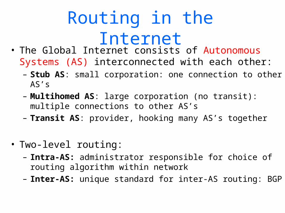
Routing in the Internet• The Global Internet consists of Autonomous
Systems (AS) interconnected with each other:– Stub AS: small corporation: one connection to other
AS’s– Multihomed AS: large corporation (no transit):
multiple connections to other AS’s– Transit AS: provider, hooking many AS’s together
• Two-level routing: – Intra-AS: administrator responsible for choice of
routing algorithm within network– Inter-AS: unique standard for inter-AS routing: BGP

Internet AS HierarchyInter-AS border (exterior gateway) routers
Intra-AS (interior gateway) routers

Intra-AS Routing
• Also known as Interior Gateway Protocols (IGP)• Most common Intra-AS routing protocols:
– RIP: Routing Information Protocol
– OSPF: Open Shortest Path First
– IGRP: Interior Gateway Routing Protocol (Cisco proprietary)

Hierarchical OSPF
• Two-level hierarchy: local area, backbone.– Link-state advertisements
only in area – each nodes has detailed
area topology; only know direction (shortest path) to nets in other areas.
• Area border routers: “summarize” distances to nets in own area, advertise to other Area Border routers.
• Backbone routers: run OSPF routing limited to backbone.
• Boundary routers: connect to other AS’s.

Internet inter-AS routing: BGP• BGP (Border Gateway Protocol): the de facto
standard• Path Vector protocol:
– similar to Distance Vector protocol– each Border Gateway broadcast to neighbors
(peers) entire path (i.e., sequence of AS’s) to destination
– BGP routes to networks (ASs), not individual hosts– E.g., Gateway X may send its path to dest. Z:
Path (X,Z) = X,Y1,Y2,Y3,…,Z

Internet inter-AS routing: BGP
Suppose: gateway X send its path to peer gateway W
• W may or may not select path offered by X– cost, policy (don’t route via competitors AS),
loop prevention reasons.
• If W selects path advertised by X, then:Path (W,Z) = w, Path (X,Z)
• Note: X can control incoming traffic by controlling its route advertisements to peers:– e.g., don’t want to route traffic to Z -> don’t
advertise any routes to Z
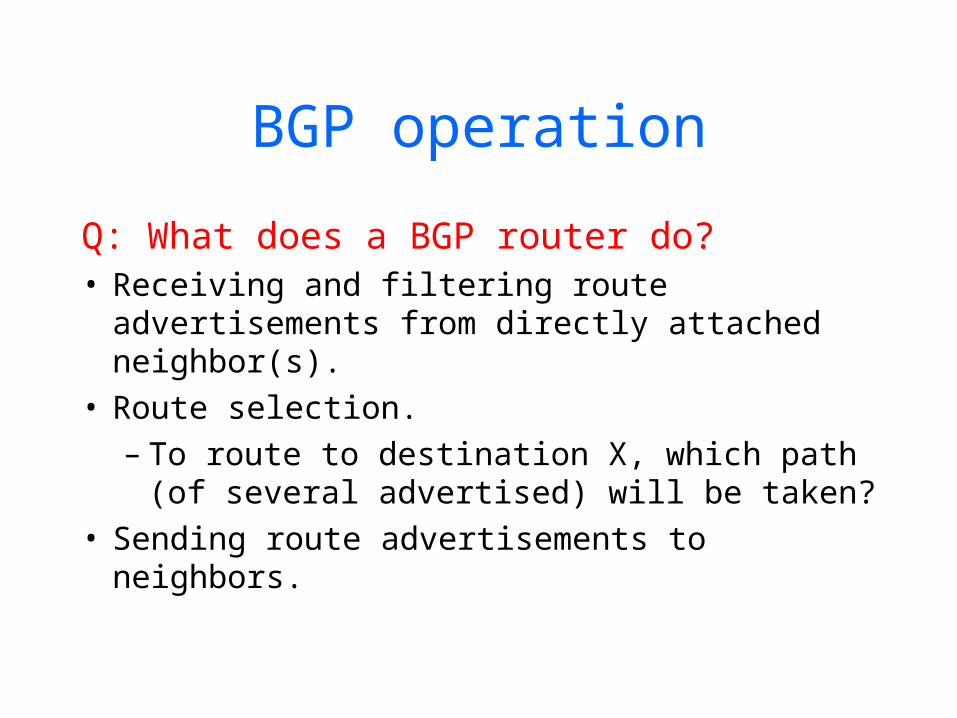
BGP operation
Q: What does a BGP router do?• Receiving and filtering route
advertisements from directly attached neighbor(s).
• Route selection. – To route to destination X, which path
(of several advertised) will be taken?• Sending route advertisements to
neighbors.
49
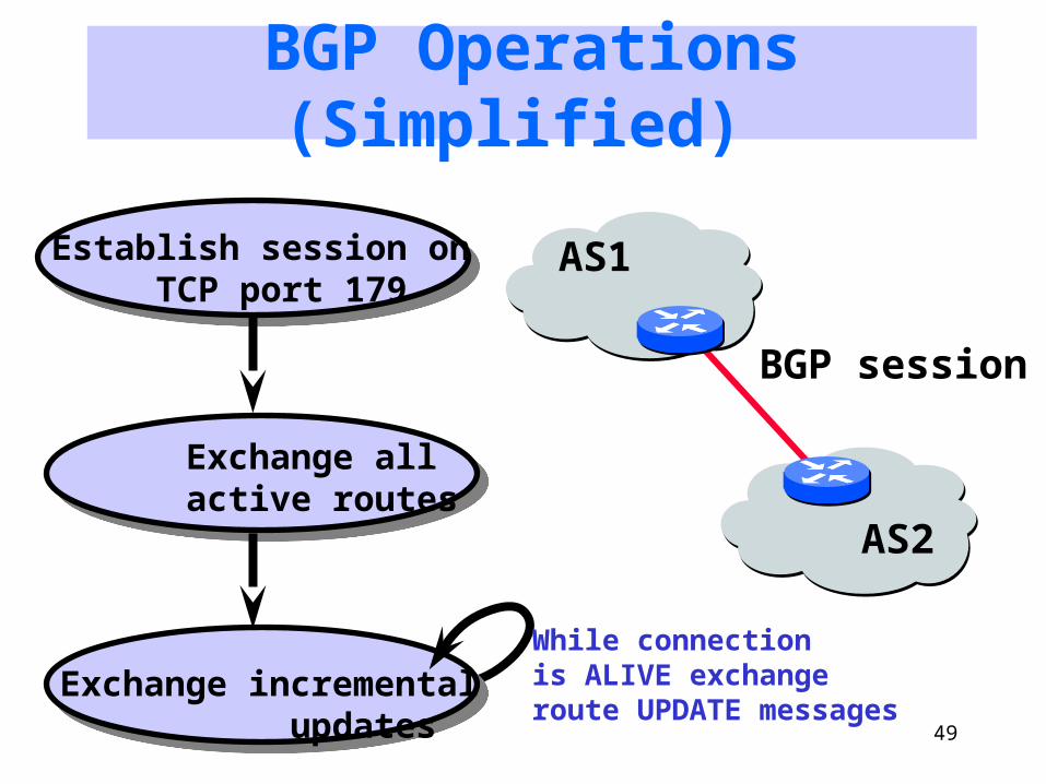
BGP Operations (Simplified)
Establish session on TCP port 179
Exchange all active routes
Exchange incremental updates
AS1
AS2
While connection is ALIVE exchangeroute UPDATE messages
BGP session

Inter-AS routing in the Internet: BGP
Figure 4.5.2-new2: BGP use for inter-domain routing
AS2 (OSPF
intra-AS routing)
AS1 (RI P intra-AS
routing) BGP
AS3 (OSPF intra-AS
routing)
BGP
R1 R2
R3
R4
R5
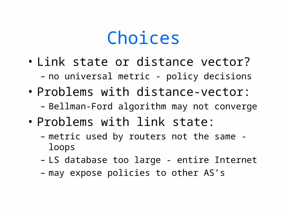
Choices• Link state or distance vector?
– no universal metric - policy decisions
• Problems with distance-vector:– Bellman-Ford algorithm may not converge
• Problems with link state:– metric used by routers not the same - loops– LS database too large - entire Internet– may expose policies to other AS’s
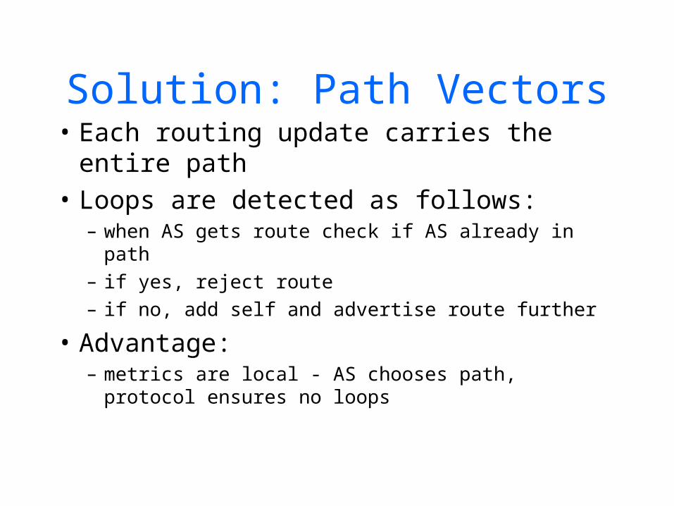
Solution: Path Vectors• Each routing update carries the
entire path• Loops are detected as follows:
– when AS gets route check if AS already in path– if yes, reject route– if no, add self and advertise route further
• Advantage:– metrics are local - AS chooses path, protocol
ensures no loops
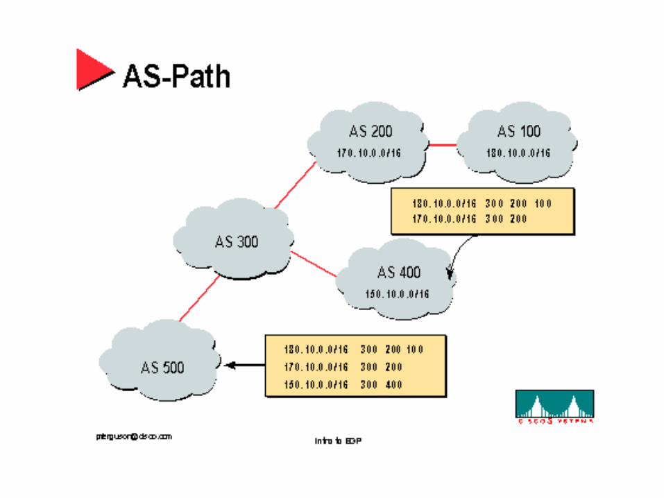
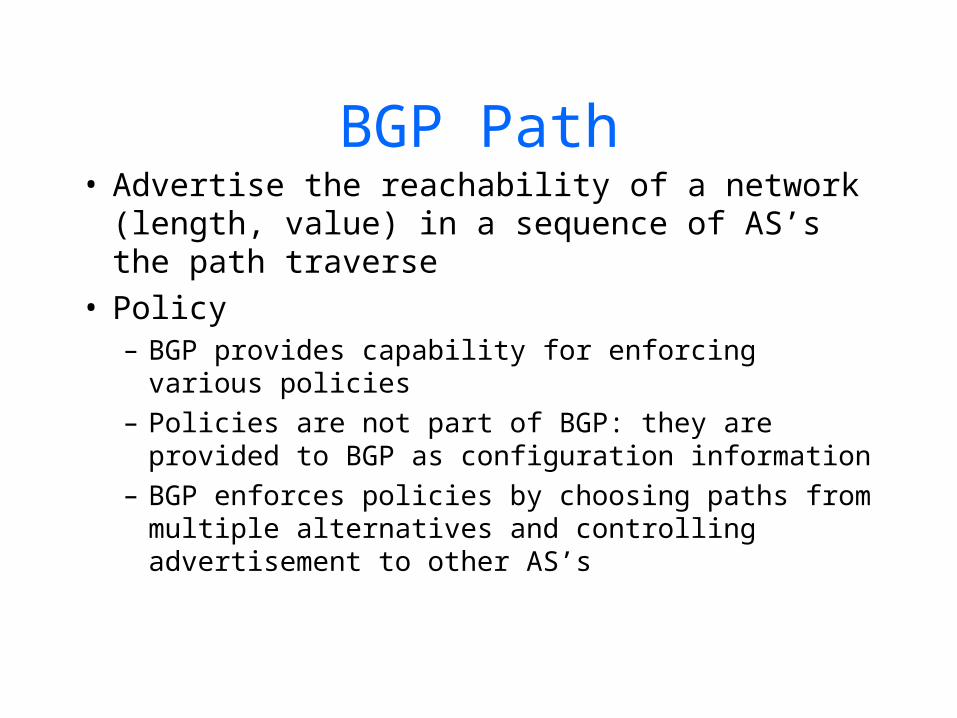
BGP Path• Advertise the reachability of a network
(length, value) in a sequence of AS’s the path traverse
• Policy– BGP provides capability for enforcing various
policies– Policies are not part of BGP: they are provided to
BGP as configuration information– BGP enforces policies by choosing paths from
multiple alternatives and controlling advertisement to other AS’s
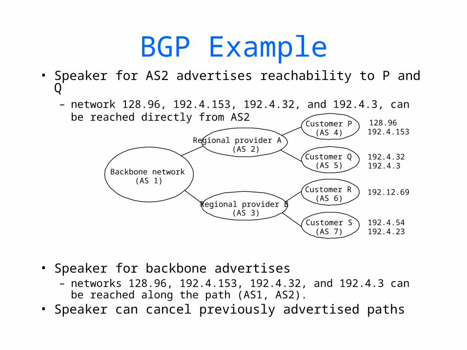
BGP Example• Speaker for AS2 advertises reachability to P and Q
– network 128.96, 192.4.153, 192.4.32, and 192.4.3, can be reached directly from AS2
• Speaker for backbone advertises– networks 128.96, 192.4.153, 192.4.32, and 192.4.3 can
be reached along the path (AS1, AS2).• Speaker can cancel previously advertised paths
Backbone network(AS 1)
Regional provider A(AS 2)
Regional provider B(AS 3)
Customer P(AS 4)
Customer Q(AS 5)
Customer R(AS 6)
Customer S(AS 7)
128.96192.4.153
192.4.32192.4.3
192.12.69
192.4.54192.4.23
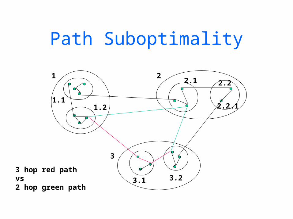
Path Suboptimality
1 2
3
1.11.2
2.1 2.2
3.1 3.2
2.2.1
3 hop red pathvs2 hop green path
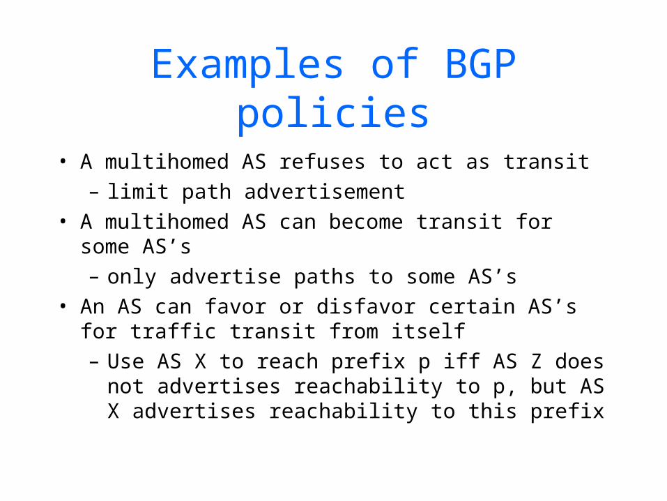
Examples of BGP policies
• A multihomed AS refuses to act as transit– limit path advertisement
• A multihomed AS can become transit for some AS’s– only advertise paths to some AS’s
• An AS can favor or disfavor certain AS’s for traffic transit from itself– Use AS X to reach prefix p iff AS Z does not
advertises reachability to p, but AS X advertises reachability to this prefix

BGP: controlling who routes to you
Figure 4.5-BGPnew: a simple BGP scenario
A
B
C
W X
Y
legend:
customer network:
provider network
• A,B,C are provider networks• X,W,Y are customer (of provider networks)• X is dual-homed: attached to two networks
– X does not want to route from B via X to C
– .. so X will not advertise to B a route to C
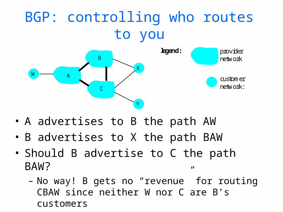
BGP: controlling who routes to you
Figure 4.5-BGPnew: a simple BGP scenario
A
B
C
W X
Y
legend:
customer network:
provider network
• A advertises to B the path AW • B advertises to X the path BAW • Should B advertise to C the path BAW?
– No way! B gets no “revenue” for routing CBAW since neither W nor C are B’s customers
– B wants to force C to route to w via A– B wants to route only to/from its customers!
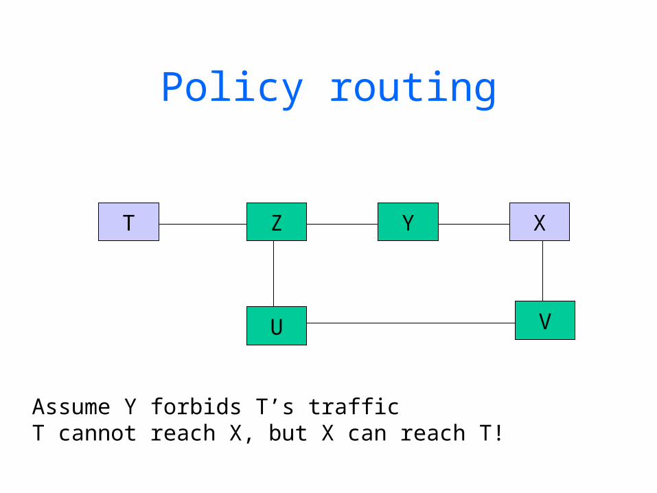
Policy routing
T Z XY
U V
Assume Y forbids T’s trafficT cannot reach X, but X can reach T!
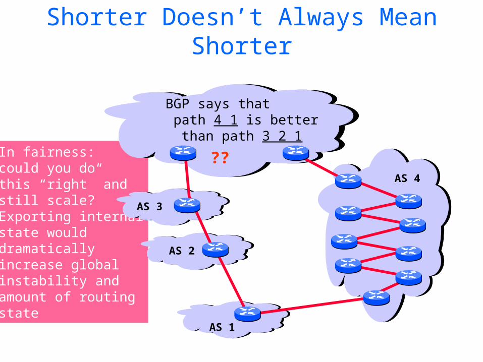
In fairness: could you do this “right” and still scale?Exporting internalstate would dramatically increase global instability and amount of routingstate
Shorter Doesn’t Always Mean Shorter
AS 4
AS 3
AS 2
AS 1
BGP says that path 4 1 is better than path 3 2 1
??
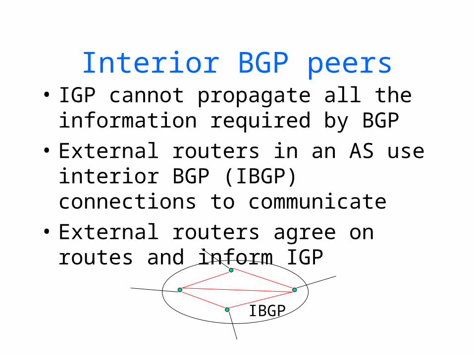
Interior BGP peers• IGP cannot propagate all the
information required by BGP• External routers in an AS use
interior BGP (IBGP) connections to communicate
• External routers agree on routes and inform IGP
IBGP
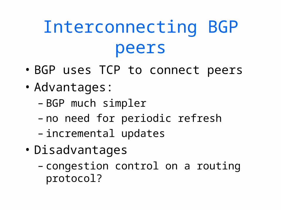
Interconnecting BGP peers
• BGP uses TCP to connect peers• Advantages:
– BGP much simpler– no need for periodic refresh– incremental updates
• Disadvantages– congestion control on a routing
protocol?
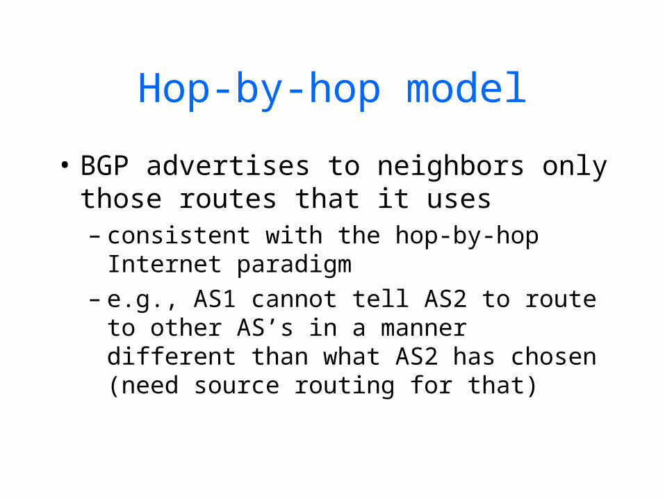
Hop-by-hop model
• BGP advertises to neighbors only those routes that it uses– consistent with the hop-by-hop
Internet paradigm– e.g., AS1 cannot tell AS2 to route to
other AS’s in a manner different than what AS2 has chosen (need source routing for that)
65
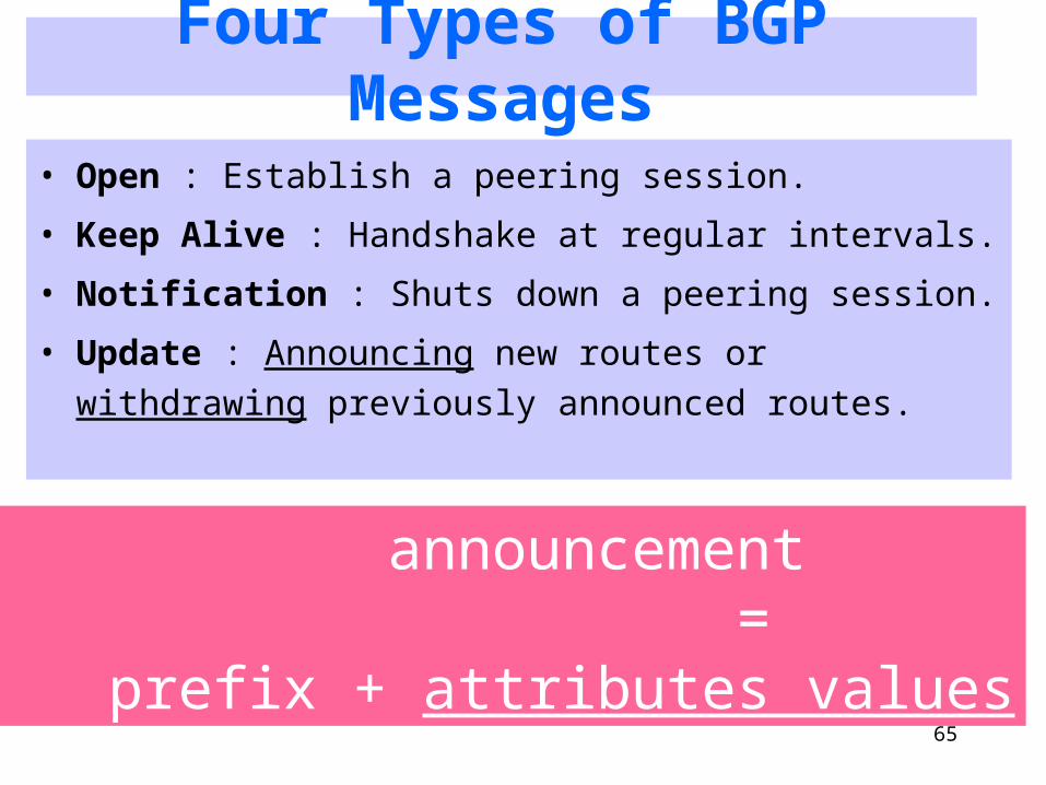
Four Types of BGP Messages
• Open : Establish a peering session.
• Keep Alive : Handshake at regular intervals.
• Notification : Shuts down a peering session.
• Update : Announcing new routes or withdrawing previously announced routes.
announcement = prefix + attributes values
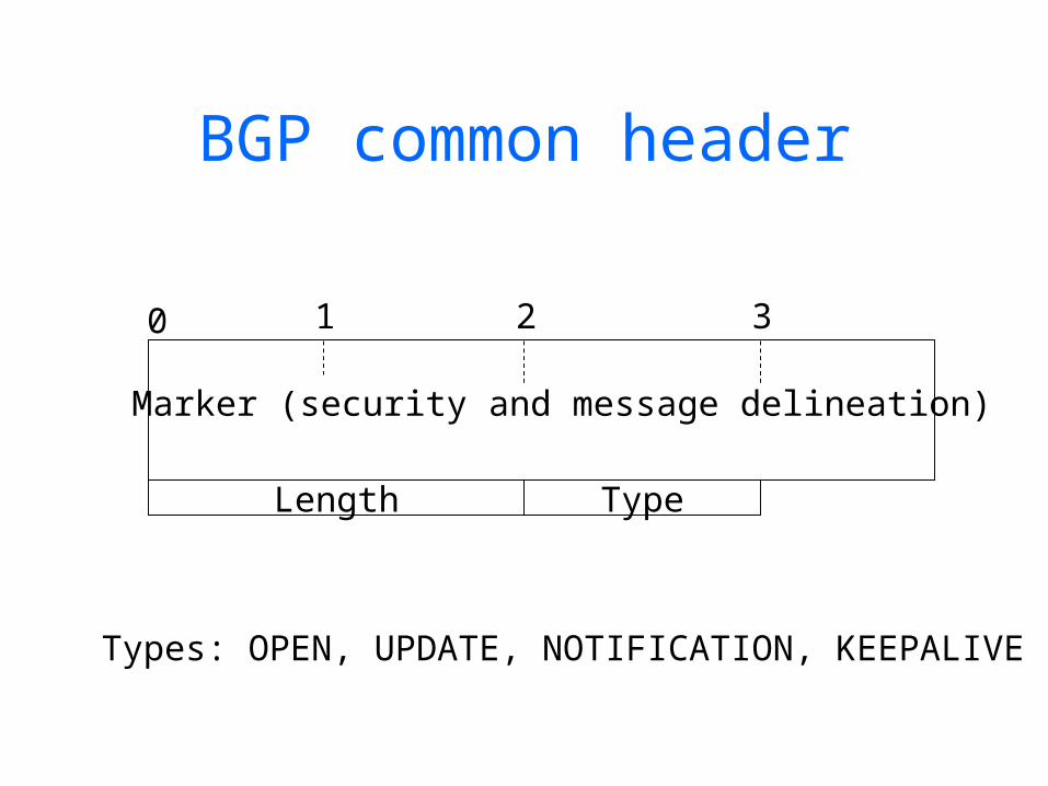
BGP common header
Length Type
0 1 2 3
Marker (security and message delineation)
Types: OPEN, UPDATE, NOTIFICATION, KEEPALIVE
Optional parameters <type, length, value>
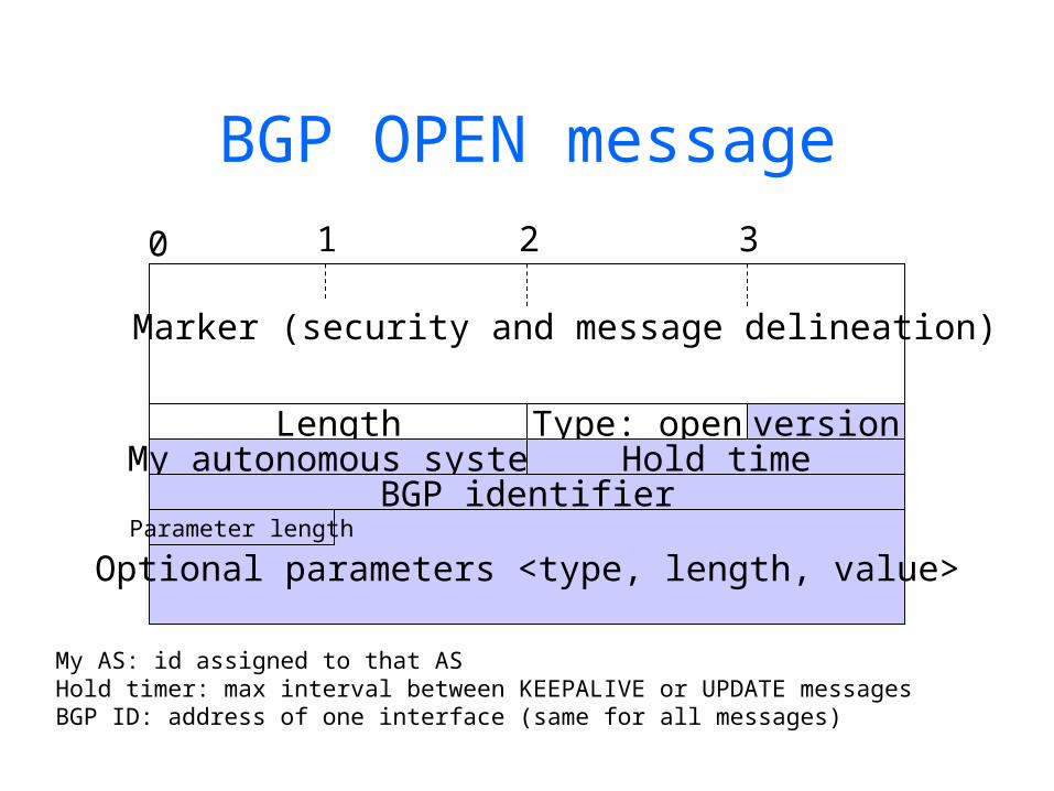
BGP OPEN message
Length Type: open
0 1 2 3
Marker (security and message delineation)
versionMy autonomous system Hold time
BGP identifierParameter length
My AS: id assigned to that ASHold timer: max interval between KEEPALIVE or UPDATE messagesBGP ID: address of one interface (same for all messages)
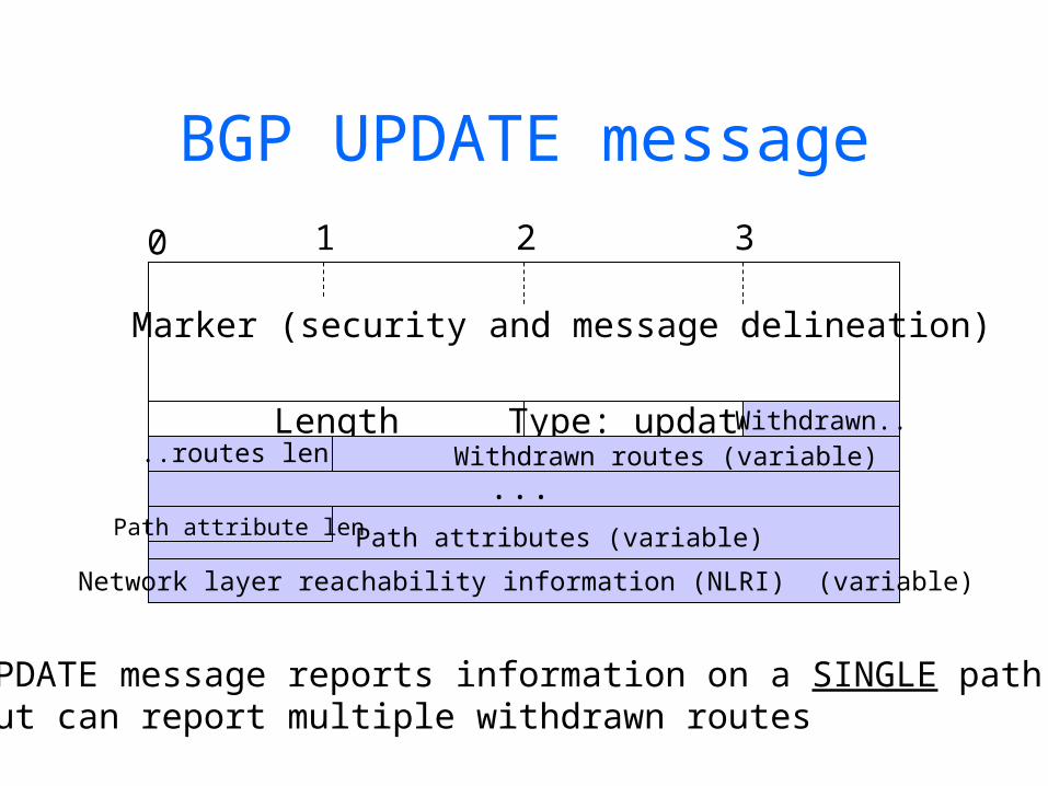
BGP UPDATE message
Length Type: update
0 1 2 3
Marker (security and message delineation)
Withdrawn....routes len Withdrawn routes (variable)
Path attribute len Path attributes (variable)
Network layer reachability information (NLRI) (variable)
UPDATE message reports information on a SINGLE path,but can report multiple withdrawn routes
...
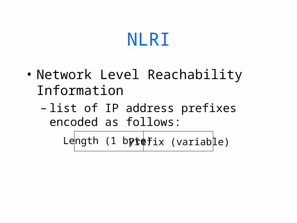
NLRI
• Network Level Reachability Information– list of IP address prefixes encoded as
follows:
Length (1 byte) Prefix (variable)

Data
BGP NOTIFICATION message
Length Type: NOTIFICATION
0 1 2 3
Marker (security and message delineation)
Error code
Error sub-code
Used for error notification

BGP KEEPALIVE message
Length Type: KEEPALIVE
0 1 2 3
Marker (security and message delineation)
Sent periodically to peers to ensure connectivityIf hold_time is zero, messages are not sent
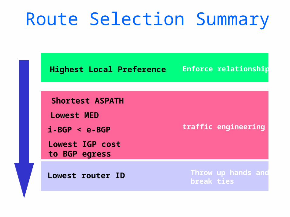
Route Selection Summary
Highest Local Preference
Shortest ASPATH
Lowest MED
i-BGP < e-BGP
Lowest IGP cost to BGP egress
Lowest router ID
traffic engineering
Enforce relationships
Throw up hands andbreak ties
73
Today’s Homework• Peterson & Davie, Chap 4
4.31 4.334.404.45
Download and browse IPv6 and BGP RFC’s

Sources
• RFC1771: main BGP RFC• RFC1772-3-4: application, experiences,
and analysis of BGP• RFC1965: AS confederations for BGP• Christian Huitema’s book “Routing in
the Internet”, chapters 8 and 9.• http://www.academ.com/nanog/feb1997
/BGPTutorial/sld022.htm (Cisco tutorial)