ECE544: Communication Networks-II, Spring 2007 Sanjoy Paul Lecture 8 Includes teaching materials...
177
ECE544: Communication Networks-II, Spring 2007 Sanjoy Paul Lecture 8 Includes teaching materials from L. Peterson, J. Kurose, K. Almeroth
-
Upload
brittany-beasley -
Category
Documents
-
view
215 -
download
0
Transcript of ECE544: Communication Networks-II, Spring 2007 Sanjoy Paul Lecture 8 Includes teaching materials...

ECE544: Communication Networks-II, Spring 2007
Sanjoy PaulLecture 8
Includes teaching materials from L. Peterson, J. Kurose, K. Almeroth

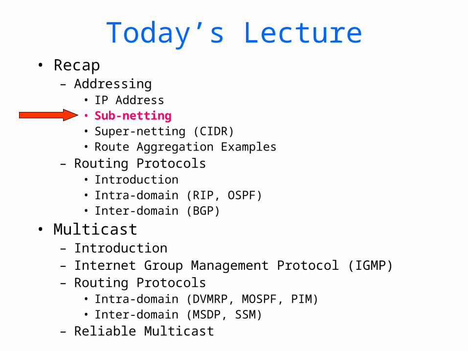
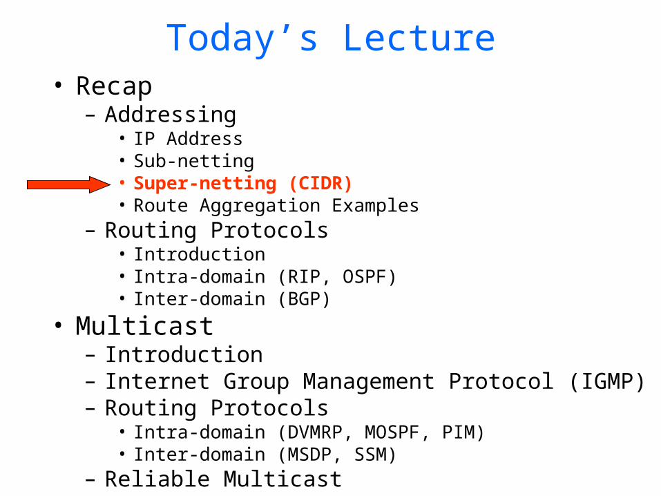
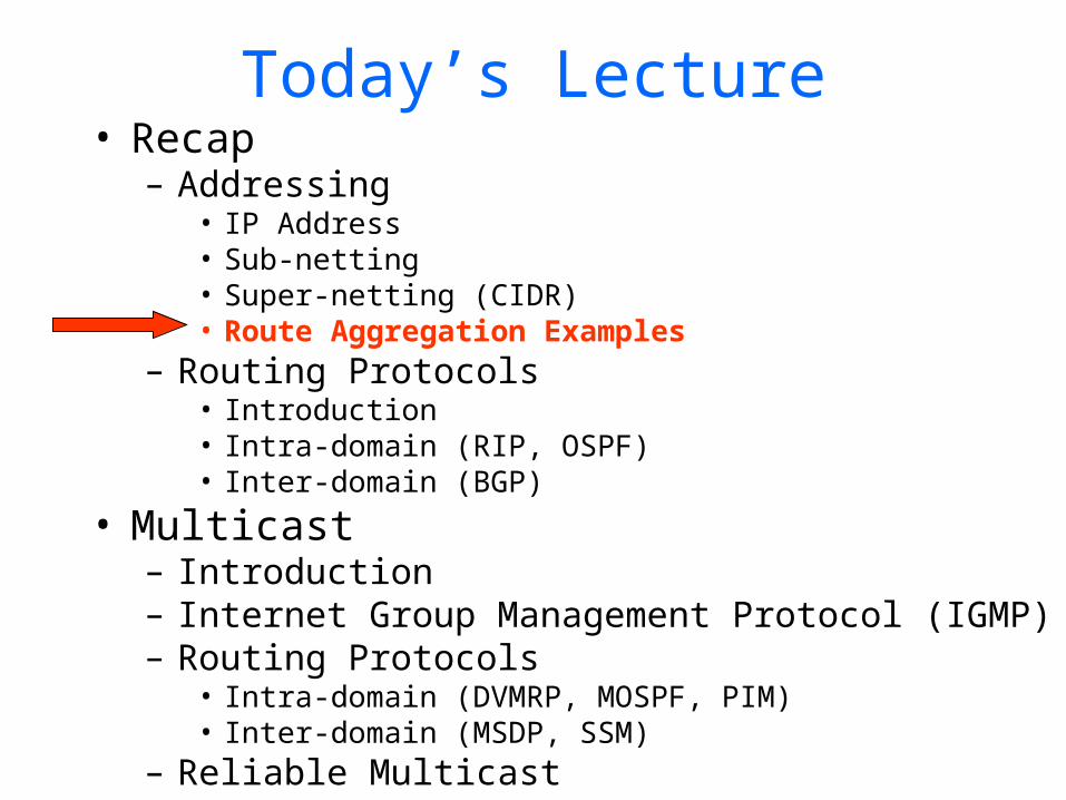
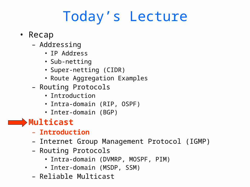
Today’s Lecture• Recap
– Addressing• IP Address• Sub-netting• Super-netting (CIDR)• Route Aggregation Examples
– Routing Protocols• Introduction• Intra-domain (RIP, OSPF)• Inter-domain (BGP)
• Multicast– Introduction – Internet Group Management Protocol (IGMP)– Routing Protocols
• Intra-domain (DVMRP, MOSPF, PIM)• Inter-domain (MSDP, SSM)
– Reliable Multicast
IP Address
0network host
10 network host
110 network host
1110 multicast address
A
B
C
D
class1.0.0.0 to127.255.255.255
128.0.0.0 to191.255.255.255
192.0.0.0 to223.255.255.255
224.0.0.0 to239.255.255.255
32 bits
“class-full” addressing:
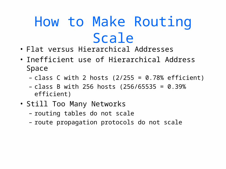
How to Make Routing Scale
• Flat versus Hierarchical Addresses• Inefficient use of Hierarchical Address Space
– class C with 2 hosts (2/255 = 0.78% efficient)– class B with 256 hosts (256/65535 = 0.39%
efficient)
• Still Too Many Networks– routing tables do not scale– route propagation protocols do not scale
Today’s Lecture• Recap
– Addressing• IP Address• Sub-netting• Super-netting (CIDR)• Route Aggregation Examples
– Routing Protocols• Introduction• Intra-domain (RIP, OSPF)• Inter-domain (BGP)
• Multicast– Introduction– Internet Group Management Protocol (IGMP)– Routing Protocols
• Intra-domain (DVMRP, MOSPF, PIM)• Inter-domain (MSDP, SSM)
– Reliable Multicast
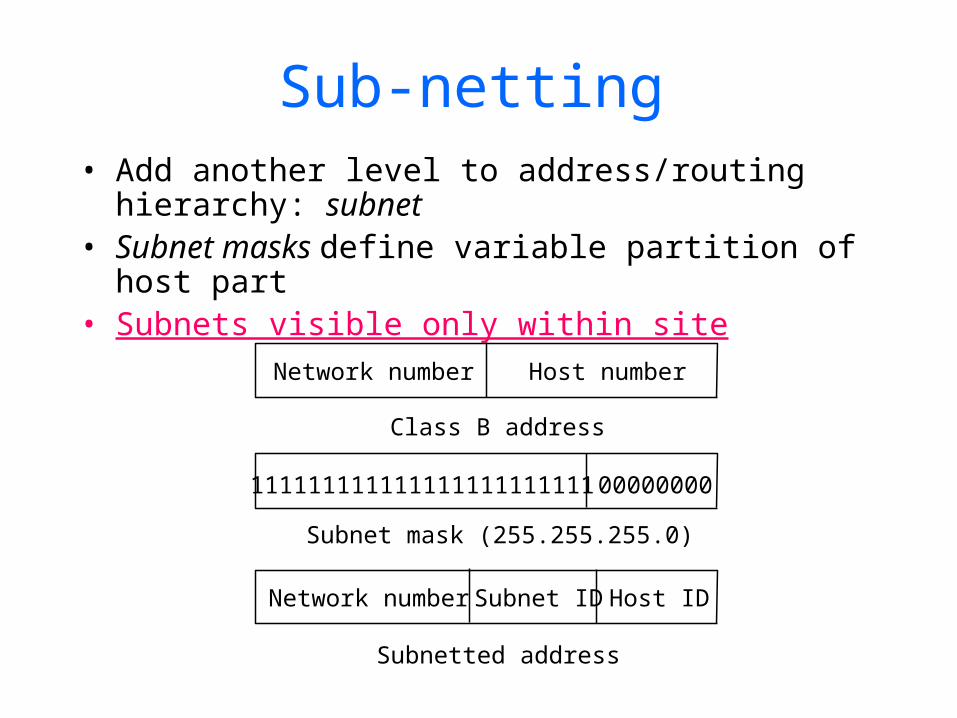
Sub-netting• Add another level to address/routing hierarchy:
subnet• Subnet masks define variable partition of host
part• Subnets visible only within site
Network number Host number
Class B address
Subnet mask (255.255.255.0)
Subnetted address
111111111111111111111111 00000000
Network number Host IDSubnet ID
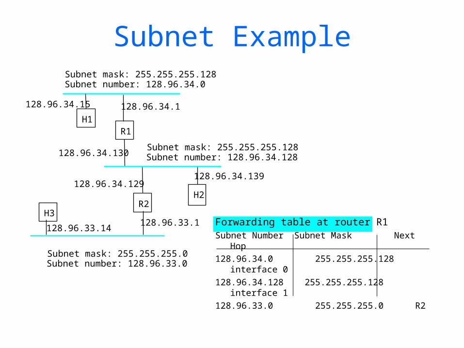
Subnet Example
Forwarding table at router R1Subnet Number Subnet Mask Next
Hop128.96.34.0 255.255.255.128
interface 0128.96.34.128 255.255.255.128
interface 1128.96.33.0 255.255.255.0 R2
Subnet mask: 255.255.255.128Subnet number: 128.96.34.0
128.96.34.15 128.96.34.1
H1R1
128.96.34.130Subnet mask: 255.255.255.128Subnet number: 128.96.34.128
128.96.34.129128.96.34.139
R2H2
128.96.33.1128.96.33.14
Subnet mask: 255.255.255.0Subnet number: 128.96.33.0
H3
Today’s Lecture• Recap
– Addressing• IP Address• Sub-netting• Super-netting (CIDR)• Route Aggregation Examples
– Routing Protocols• Introduction• Intra-domain (RIP, OSPF)• Inter-domain (BGP)
• Multicast– Introduction– Internet Group Management Protocol (IGMP)– Routing Protocols
• Intra-domain (DVMRP, MOSPF, PIM)• Inter-domain (MSDP, SSM)
– Reliable Multicast
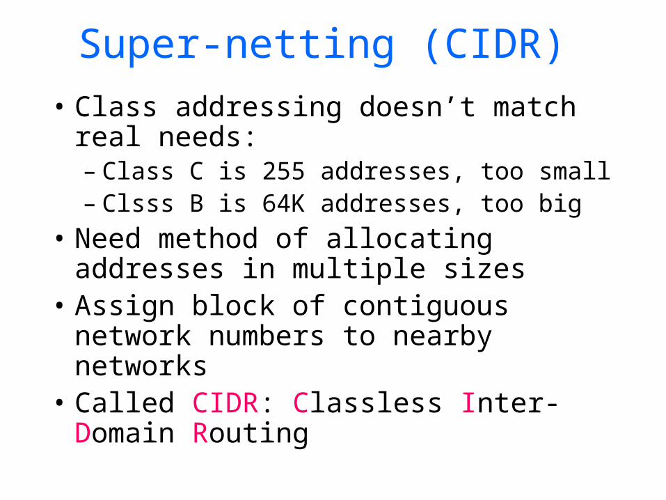
Super-netting (CIDR)• Class addressing doesn’t match real
needs:– Class C is 255 addresses, too small– Clsss B is 64K addresses, too big
• Need method of allocating addresses in multiple sizes
• Assign block of contiguous network numbers to nearby networks
• Called CIDR: Classless Inter-Domain Routing

Classless Inter Domain Routing (CIDR)
Class B:
Class C:
Net ID Host ID
Host IDNet ID
Problem: Class B addresses are running out Solution: Allocate multiple Class C addresses Problem: Random allocation of Class C addresses need multiple routing table entries Solution: Allocate “contiguous” Class C addresses Routing entry: [IP Address of Network and Net Mask]
IP Address: 195.201.3.5 = 11000011 11001001 00000011 00000101Net Mask: 254.0.0.0 = 11111110 00000000 00000000 00000000-----------------------------------------------------------------------------------------Network IP: 194.0.0.0 = 11000010 00000000 00000000 00000000
CIDR (continued)
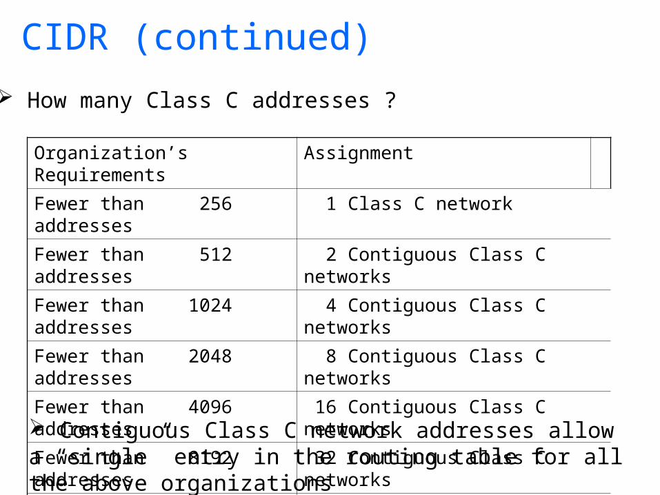
Organization’s Requirements Assignment
Fewer than 256 addresses 1 Class C network
Fewer than 512 addresses 2 Contiguous Class C networks
Fewer than 1024 addresses 4 Contiguous Class C networks
Fewer than 2048 addresses 8 Contiguous Class C networks
Fewer than 4096 addresses 16 Contiguous Class C networks
Fewer than 8192 addresses 32 Contiguous Class C networks
Fewer than 16384 addresses 64 Contiguous Class C networks
How many Class C addresses ?
Contiguous Class C network addresses allow a “single” entry in the routing table for all the above organizations

Coordinated Address Allocation
Multi-regional 192.0.0.0 -- 193.255.255.255
Europe 194.0.0.0 -- 195.255.255.255
Others 196.0.0.0 -- 197.255.255.255
North America 198.0.0.0 -- 199.255.255.255
Central/South America 200.0.0.0 -- 201.255.255.255
Pacific Rim 202.0.0.0 -- 203.255.255.255
Others 204.0.0.0 -- 205.255.255.255
Others 206.0.0.0 -- 207.255.255.255
Address aggregation using Geographic scope
European networks will have a single entry in routing tables of routers in other continents: [Network IP =194.0.0.0; mask = 254.0.0.0]194.0.0.0 = 10110010 00000000 00000000 00000000195.255.255.255 = 10110011 11111111 11111111 11111111
Same 7 high-order bits implies Mask = 11111110 00000000 00000000 00000000 = 254.0.0.0
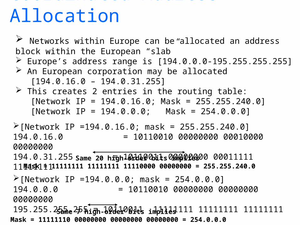
Coordinated Address Allocation Networks within Europe can be allocated an address block within the European “slab” Europe’s address range is [194.0.0.0-195.255.255.255] An European corporation may be allocated [194.0.16.0 – 194.0.31.255] This creates 2 entries in the routing table: [Network IP = 194.0.16.0; Mask = 255.255.240.0] [Network IP = 194.0.0.0; Mask = 254.0.0.0]
[Network IP =194.0.16.0; mask = 255.255.240.0]194.0.16.0 = 10110010 00000000 00010000 00000000194.0.31.255 = 10110011 00000000 00011111 11111111
Same 7 high-order bits implies Mask = 11111110 00000000 00000000 00000000 = 254.0.0.0
[Network IP =194.0.0.0; mask = 254.0.0.0]194.0.0.0 = 10110010 00000000 00000000 00000000195.255.255.255 = 10110011 11111111 11111111 11111111
Same 20 high-order bits implies Mask = 11111111 11111111 11110000 00000000 = 255.255.240.0
Today’s Lecture• Recap
– Addressing• IP Address• Sub-netting• Super-netting (CIDR)• Route Aggregation Examples
– Routing Protocols• Introduction• Intra-domain (RIP, OSPF)• Inter-domain (BGP)
• Multicast– Introduction– Internet Group Management Protocol (IGMP)– Routing Protocols
• Intra-domain (DVMRP, MOSPF, PIM)• Inter-domain (MSDP, SSM)
– Reliable Multicast
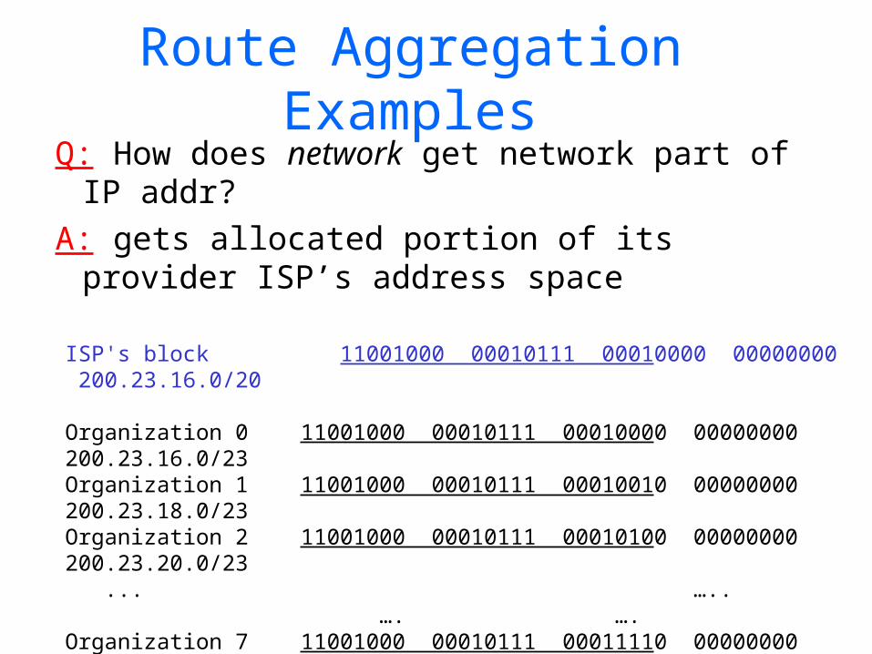
Route Aggregation Examples
Q: How does network get network part of IP addr?
A: gets allocated portion of its provider ISP’s address space
ISP's block 11001000 00010111 00010000 00000000 200.23.16.0/20
Organization 0 11001000 00010111 00010000 00000000 200.23.16.0/23 Organization 1 11001000 00010111 00010010 00000000 200.23.18.0/23 Organization 2 11001000 00010111 00010100 00000000 200.23.20.0/23 ... ….. …. ….
Organization 7 11001000 00010111 00011110 00000000 200.23.30.0/23

Hierarchical addressing: route aggregation
“Send me anythingwith addresses beginning 200.23.16.0/20”
200.23.16.0/23
200.23.18.0/23
200.23.30.0/23
Fly-By-Night-ISP
Organization 0
Organization 7Internet
Organization 1
ISPs-R-Us“Send me anythingwith addresses beginning 199.31.0.0/16”
200.23.20.0/23Organization 2
...
...
Hierarchical addressing allows efficient advertisement of routing information:

Hierarchical addressing: more specific routes
ISPs-R-Us has a more specific route to Organization 1
“Send me anythingwith addresses beginning 200.23.16.0/20”
200.23.16.0/23
200.23.18.0/23
200.23.30.0/23
Fly-By-Night-ISP
Organization 0
Organization 7Internet
Organization 1
ISPs-R-Us“Send me anythingwith addresses beginning 199.31.0.0/16or 200.23.18.0/23”
200.23.20.0/23Organization 2
...
...

Chapter 4, Figure 26
Border gateway(advertises path to
11000000000001)
Regional network
Corporation X(11000000000001000001)
Corporation Y(11000000000001000000)
Route Aggregation with CIDR
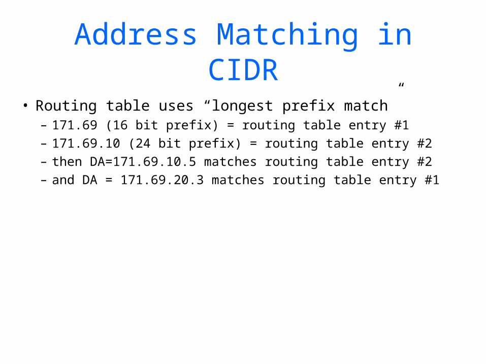
Address Matching in CIDR
• Routing table uses “longest prefix match”– 171.69 (16 bit prefix) = routing table entry #1– 171.69.10 (24 bit prefix) = routing table entry #2– then DA=171.69.10.5 matches routing table entry #2– and DA = 171.69.20.3 matches routing table entry
#1

CIDR (Summary)
• Continuous block of 2N addresses• [Base address, Mask]• Lookup algorithm:
– Masks destination address against mask in routing table entry
– Match means route is found – May be multiple matchings! – Longest mask breaks “ties” (longest prefix
match)
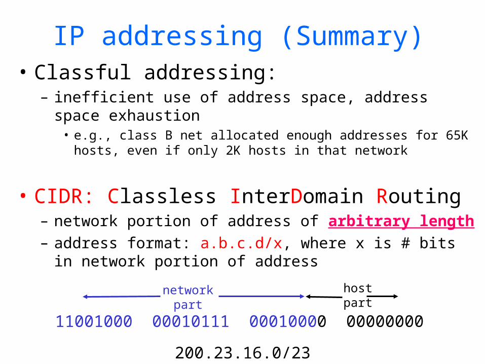
IP addressing (Summary)• Classful addressing:
– inefficient use of address space, address space exhaustion
• e.g., class B net allocated enough addresses for 65K hosts, even if only 2K hosts in that network
• CIDR: Classless InterDomain Routing– network portion of address of arbitrary length– address format: a.b.c.d/x, where x is # bits in
network portion of address
11001000 00010111 00010000 00000000
networkpart
hostpart
200.23.16.0/23

Today’s Lecture• Recap
– Addressing• IP Address• Sub-netting• Super-netting (CIDR)• Route Aggregation Examples
– Routing Protocols• Introduction• Intra-domain (RIP, OSPF)• Inter-domain (BGP)
• Multicast– Introduction– Internet Group Management Protocol (IGMP)– Routing Protocols
• Intra-domain (DVMRP, MOSPF, PIM)• Inter-domain (MSDP, SSM)
– Reliable Multicast
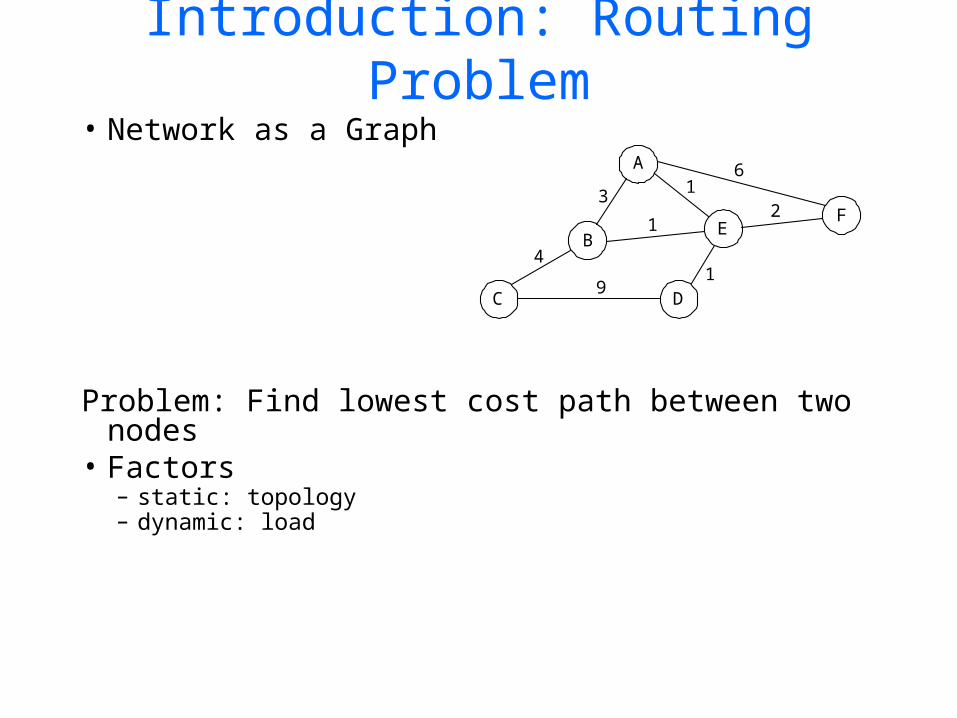
Introduction: Routing Problem
• Network as a Graph
Problem: Find lowest cost path between two nodes
• Factors– static: topology– dynamic: load
4
3
6
21
9
1
1D
A
FE
B
C
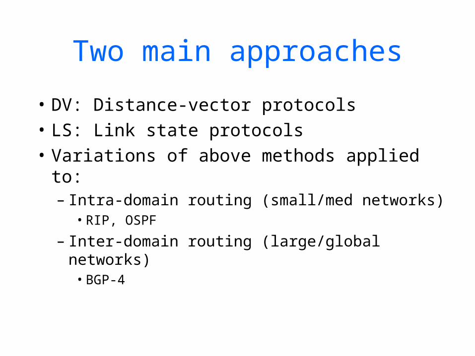
Two main approaches
• DV: Distance-vector protocols• LS: Link state protocols• Variations of above methods applied to:
– Intra-domain routing (small/med networks)• RIP, OSPF
– Inter-domain routing (large/global networks)• BGP-4

Routing in the Internet• The Global Internet consists of Autonomous
Systems (AS) interconnected with each other:– Stub AS: small corporation: one connection to other
AS’s– Multihomed AS: large corporation (no transit):
multiple connections to other AS’s– Transit AS: provider, hooking many AS’s together
• Two-level routing: – Intra-AS: administrator responsible for choice of
routing algorithm within network– Inter-AS: unique standard for inter-AS routing: BGP
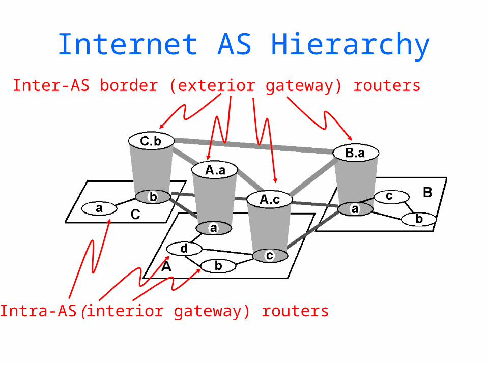
Internet AS HierarchyInter-AS border (exterior gateway) routers
Intra-AS (interior gateway) routers

Intra-AS Routing
• Also known as Interior Gateway Protocols (IGP)• Most common Intra-AS routing protocols:
– RIP: Routing Information Protocol
– OSPF: Open Shortest Path First
– IGRP: Interior Gateway Routing Protocol (Cisco proprietary)
Today’s Lecture• Recap
– Addressing• IP Address• Sub-netting• Super-netting (CIDR)• Route Aggregation Examples
– Routing Protocols• Introduction• Intra-domain (RIP, OSPF)• Inter-domain (BGP)
• Multicast– Introduction– Internet Group Management Protocol (IGMP)– Routing Protocols
• Intra-domain (DVMRP, MOSPF, PIM)• Inter-domain (MSDP, SSM)
– Reliable Multicast

RIP ( Routing Information Protocol)
• Distance vector algorithm• Included in BSD-UNIX Distribution in 1982• Distance metric: # of hops (max = 15
hops)– Can you guess why?
• Distance vectors: exchanged among neighbors every 30 sec via Response Message (also called advertisement)
• Each advertisement: list of up to 25 destination nets within AS
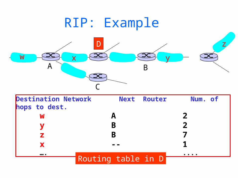
RIP: Example
Destination Network Next Router Num. of hops to dest. w A 2
y B 2 z B 7
x -- 1…. …. ....
w x y
z
A
C
D
B
Routing table in D
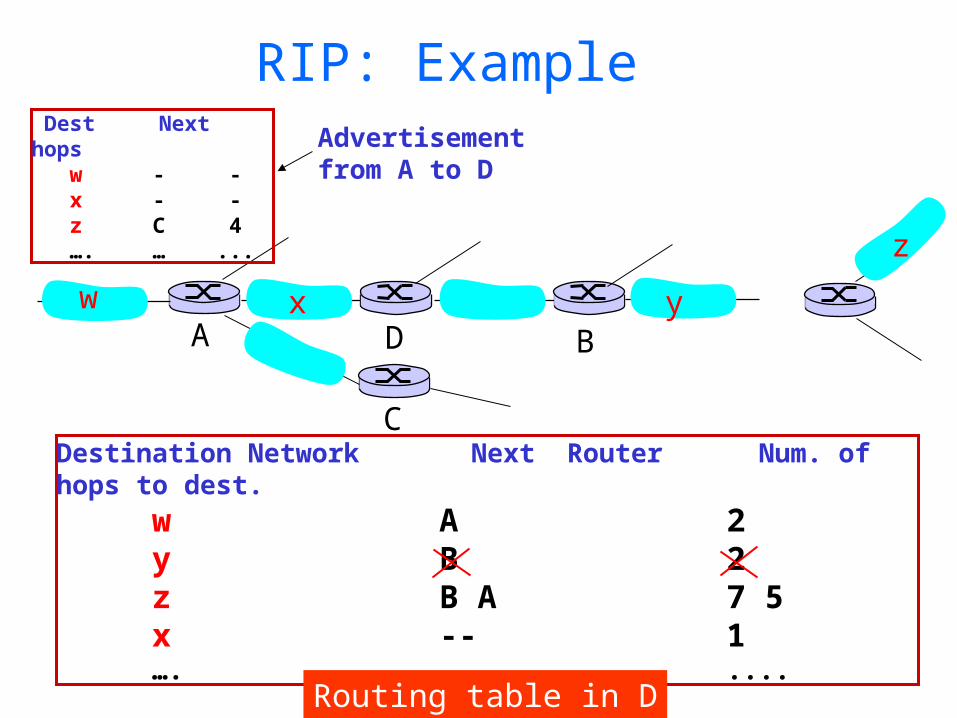
RIP: Example
Destination Network Next Router Num. of hops to dest. w A 2
y B 2 z B A 7 5
x -- 1…. …. ....
w x y
z
A
C
D B
Dest Next hops w - - x - - z C 4 …. … ...
Advertisementfrom A to D
Routing table in D
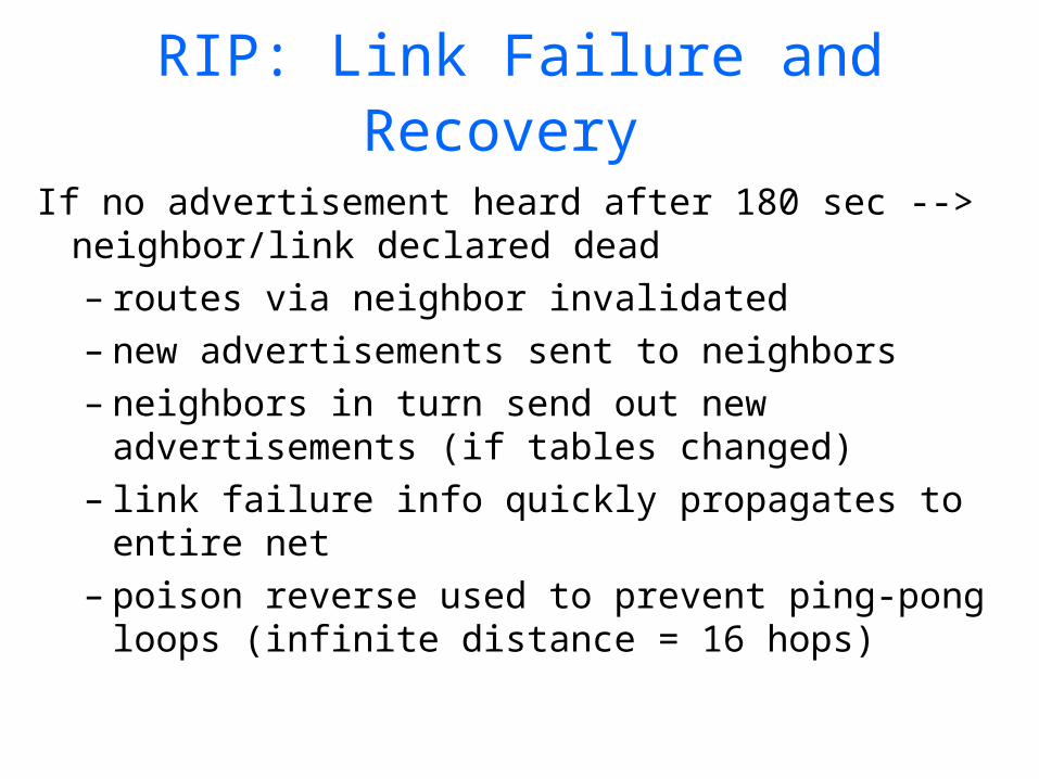
RIP: Link Failure and Recovery
If no advertisement heard after 180 sec --> neighbor/link declared dead– routes via neighbor invalidated– new advertisements sent to neighbors– neighbors in turn send out new
advertisements (if tables changed)– link failure info quickly propagates to
entire net– poison reverse used to prevent ping-pong
loops (infinite distance = 16 hops)

RIP Table processing• RIP routing tables managed by
application-level process called route-d (daemon)
• advertisements sent in UDP packets, periodically repeated
physical
link
network forwarding (IP) table
Transprt (UDP)
routed
physical
link
network (IP)
Transprt (UDP)
routed
forwardingtable
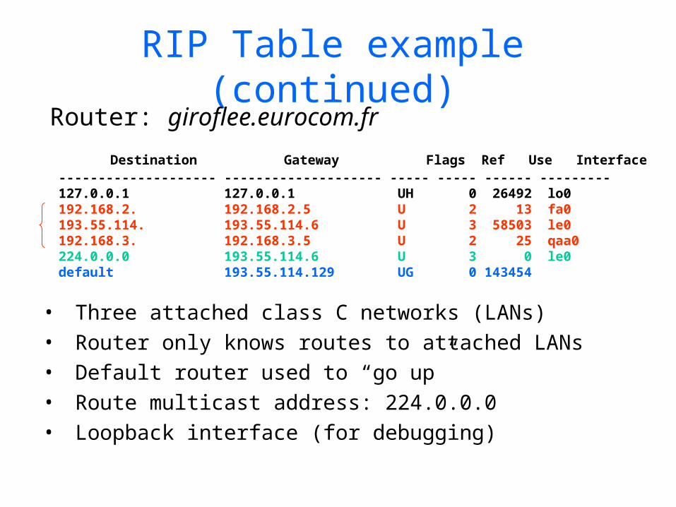
RIP Table example (continued)
Router: giroflee.eurocom.fr
• Three attached class C networks (LANs)• Router only knows routes to attached LANs• Default router used to “go up”• Route multicast address: 224.0.0.0• Loopback interface (for debugging)
Destination Gateway Flags Ref Use Interface -------------------- -------------------- ----- ----- ------ --------- 127.0.0.1 127.0.0.1 UH 0 26492 lo0 192.168.2. 192.168.2.5 U 2 13 fa0 193.55.114. 193.55.114.6 U 3 58503 le0 192.168.3. 192.168.3.5 U 2 25 qaa0 224.0.0.0 193.55.114.6 U 3 0 le0 default 193.55.114.129 UG 0 143454
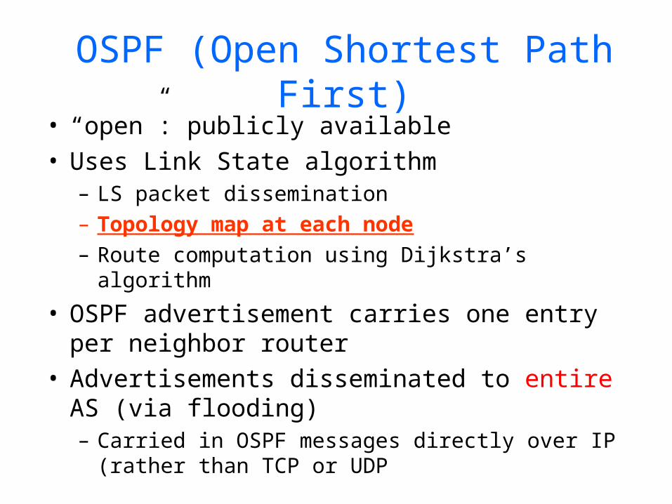
OSPF (Open Shortest Path First)
• “open”: publicly available• Uses Link State algorithm
– LS packet dissemination– Topology map at each node– Route computation using Dijkstra’s algorithm
• OSPF advertisement carries one entry per neighbor router
• Advertisements disseminated to entire AS (via flooding)– Carried in OSPF messages directly over IP
(rather than TCP or UDP

OSPF “advanced” features (not in RIP)
• Security: all OSPF messages authenticated (to prevent malicious intrusion)
• Multiple same-cost paths allowed (only one path in RIP)
• For each link, multiple cost metrics for different TOS (e.g., satellite link cost set “low” for best effort; high for real time)
• Integrated uni- and multicast support: – Multicast OSPF (MOSPF) uses same
topology data base as OSPF• Hierarchical OSPF in large domains.
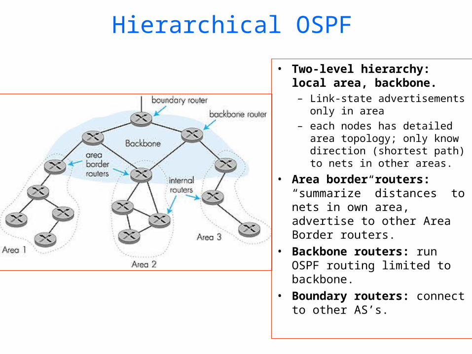
Hierarchical OSPF
• Two-level hierarchy: local area, backbone.– Link-state advertisements
only in area – each nodes has detailed
area topology; only know direction (shortest path) to nets in other areas.
• Area border routers: “summarize” distances to nets in own area, advertise to other Area Border routers.
• Backbone routers: run OSPF routing limited to backbone.
• Boundary routers: connect to other AS’s.

Today’s Lecture• Recap
– Addressing• IP Address• Sub-netting• Super-netting (CIDR)• Route Aggregation Examples
– Routing Protocols• Introduction• Intra-domain (RIP, OSPF)• Inter-domain (BGP)
• Multicast– Introduction– Internet Group Management Protocol (IGMP)– Routing Protocols
• Intra-domain (DVMRP, MOSPF, PIM)• Inter-domain (MSDP, SSM)
– Reliable Multicast
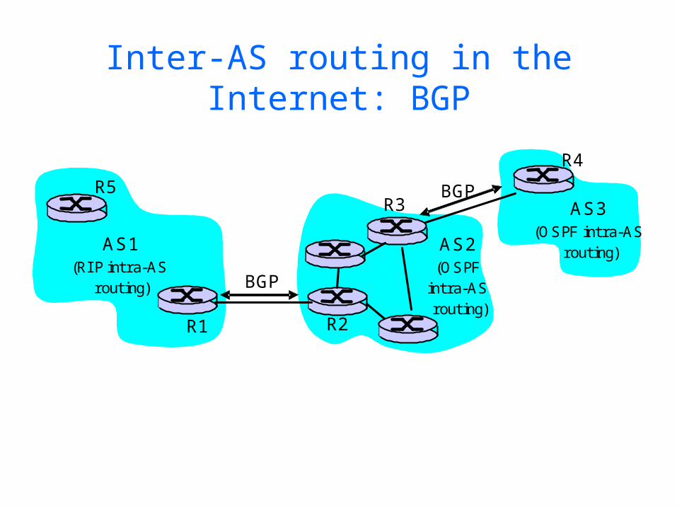
Inter-AS routing in the Internet: BGP
Figure 4.5.2-new2: BGP use for inter-domain routing
AS2 (OSPF
intra-AS routing)
AS1 (RI P intra-AS
routing) BGP
AS3 (OSPF intra-AS
routing)
BGP
R1 R2
R3
R4
R5
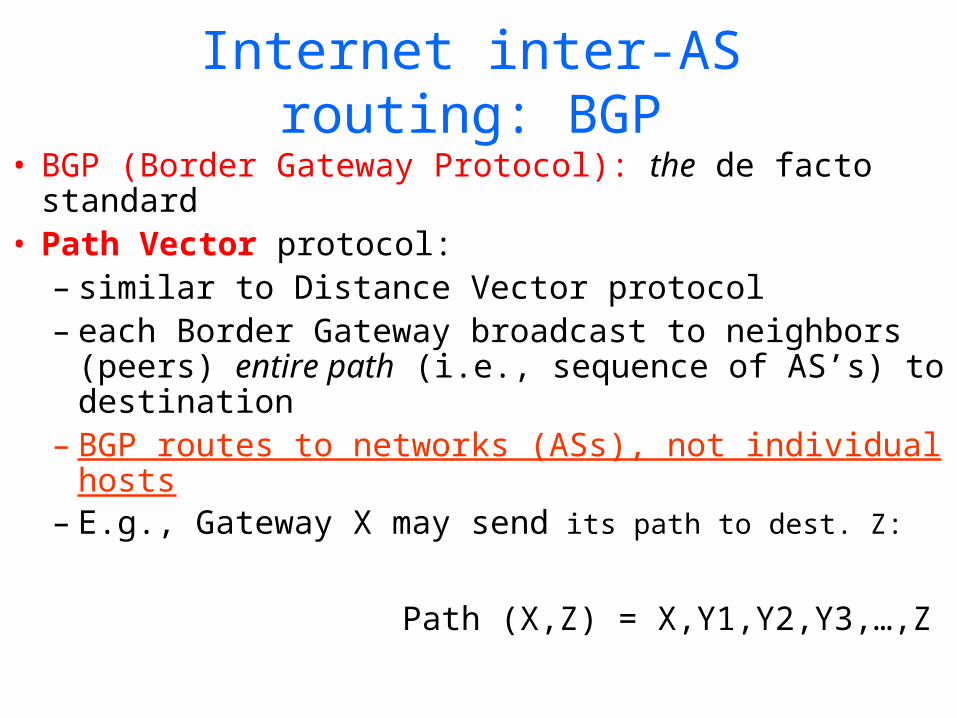
Internet inter-AS routing: BGP• BGP (Border Gateway Protocol): the de facto
standard• Path Vector protocol:
– similar to Distance Vector protocol– each Border Gateway broadcast to neighbors
(peers) entire path (i.e., sequence of AS’s) to destination
– BGP routes to networks (ASs), not individual hosts– E.g., Gateway X may send its path to dest. Z:
Path (X,Z) = X,Y1,Y2,Y3,…,Z
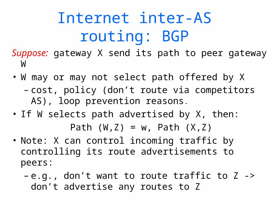
Internet inter-AS routing: BGP
Suppose: gateway X send its path to peer gateway W
• W may or may not select path offered by X– cost, policy (don’t route via competitors AS),
loop prevention reasons.
• If W selects path advertised by X, then:Path (W,Z) = w, Path (X,Z)
• Note: X can control incoming traffic by controlling its route advertisements to peers:– e.g., don’t want to route traffic to Z -> don’t
advertise any routes to Z

BGP: controlling who routes to you
Figure 4.5-BGPnew: a simple BGP scenario
A
B
C
W X
Y
legend:
customer network:
provider network
• A,B,C are provider networks• X,W,Y are customer (of provider networks)• X is dual-homed: attached to two networks
– X does not want to route from B via X to C– .. so X will not advertise to B a route to C
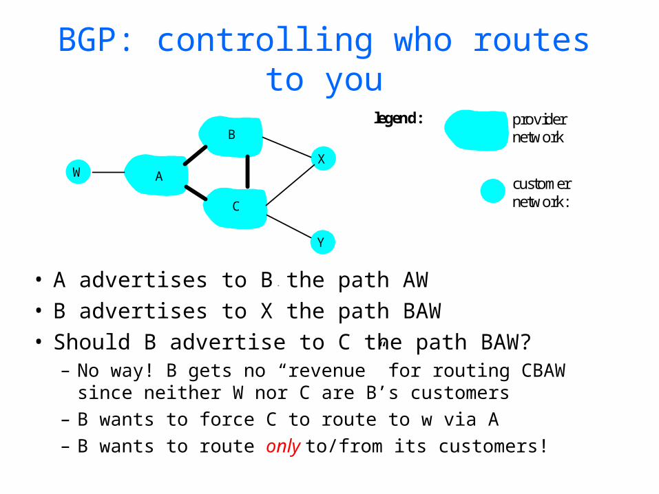
BGP: controlling who routes to you
Figure 4.5-BGPnew: a simple BGP scenario
A
B
C
W X
Y
legend:
customer network:
provider network
• A advertises to B the path AW • B advertises to X the path BAW • Should B advertise to C the path BAW?
– No way! B gets no “revenue” for routing CBAW since neither W nor C are B’s customers
– B wants to force C to route to w via A– B wants to route only to/from its customers!

BGP operation
Q: What does a BGP router do?• Receiving and filtering route
advertisements from directly attached neighbor(s).
• Route selection. – To route to destination X, which path
(of several advertised) will be taken?• Sending route advertisements to
neighbors.
45
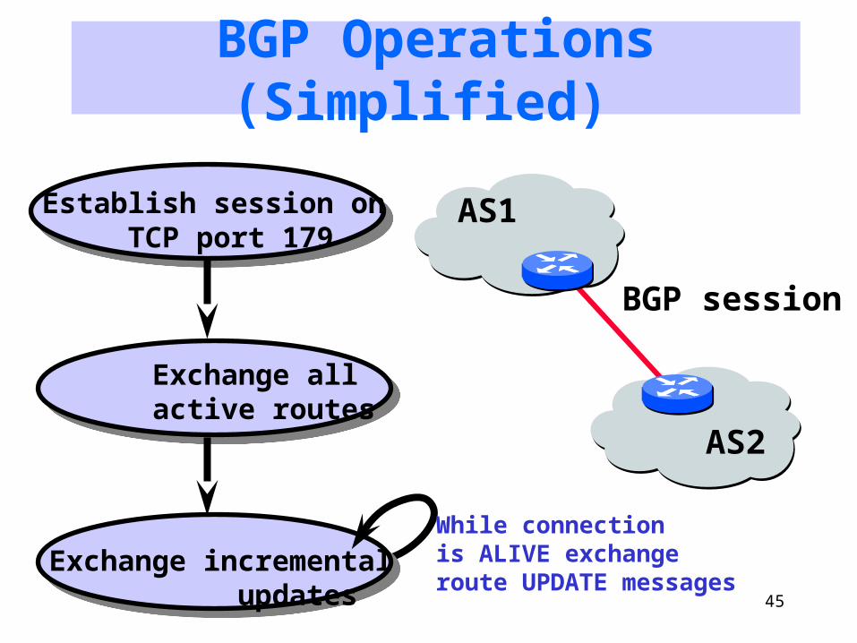
BGP Operations (Simplified)
Establish session on TCP port 179
Exchange all active routes
Exchange incremental updates
AS1
AS2
While connection is ALIVE exchangeroute UPDATE messages
BGP session
46
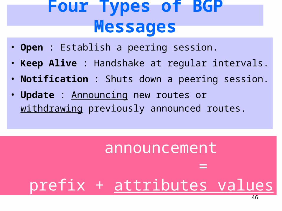
Four Types of BGP Messages
• Open : Establish a peering session.
• Keep Alive : Handshake at regular intervals.
• Notification : Shuts down a peering session.
• Update : Announcing new routes or withdrawing previously announced routes.
announcement = prefix + attributes values

BGP Attributes
Value Code Reference----- --------------------------------- --------- 1 ORIGIN [RFC1771] 2 AS_PATH [RFC1771] 3 NEXT_HOP [RFC1771] 4 MULTI_EXIT_DISC [RFC1771] 5 LOCAL_PREF [RFC1771] 6 ATOMIC_AGGREGATE [RFC1771] 7 AGGREGATOR [RFC1771] 8 COMMUNITY [RFC1997] 9 ORIGINATOR_ID [RFC2796] 10 CLUSTER_LIST [RFC2796] 11 DPA [Chen] 12 ADVERTISER [RFC1863] 13 RCID_PATH / CLUSTER_ID [RFC1863] 14 MP_REACH_NLRI [RFC2283] 15 MP_UNREACH_NLRI [RFC2283] 16 EXTENDED COMMUNITIES [Rosen] ... 255 reserved for development
From IANA: http://www.iana.org/assignments/bgp-parameters
Mostimportantattributes
Not all attributesneed to be present inevery announcement
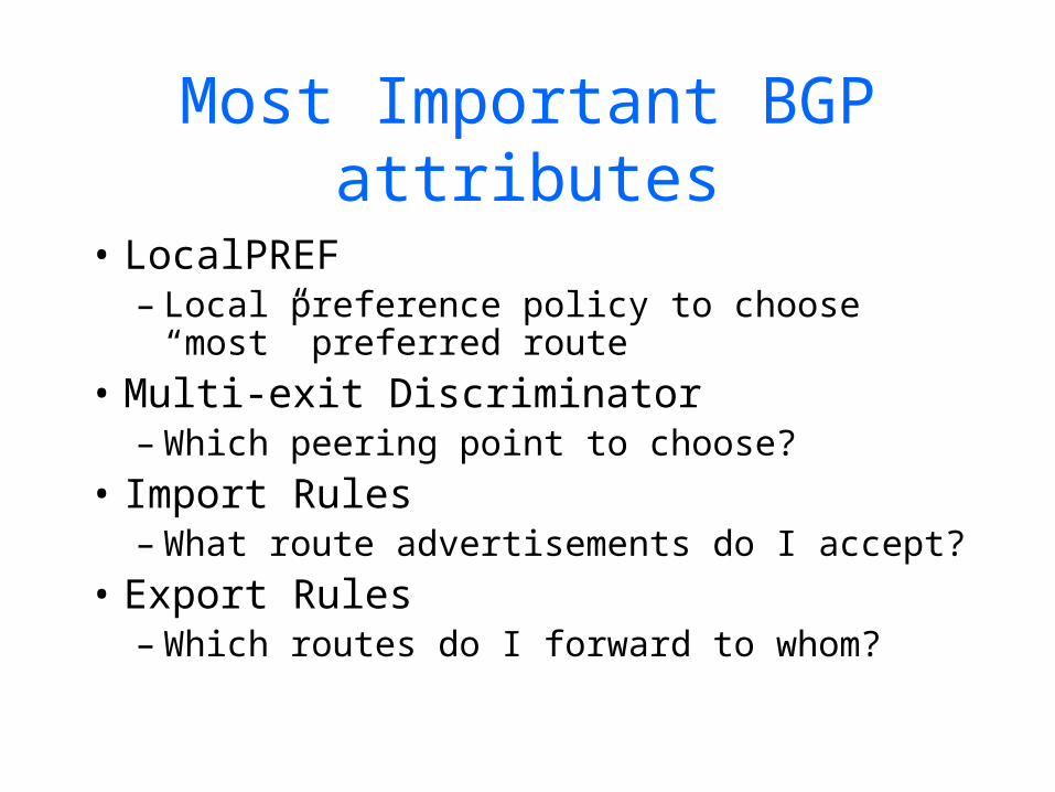
Most Important BGP attributes
• LocalPREF– Local preference policy to choose “most”
preferred route• Multi-exit Discriminator
– Which peering point to choose?• Import Rules
– What route advertisements do I accept?• Export Rules
– Which routes do I forward to whom?
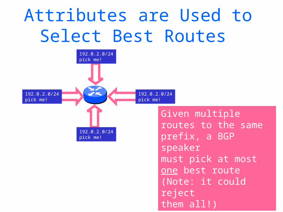
Attributes are Used to Select Best Routes
192.0.2.0/24pick me!
192.0.2.0/24pick me!
192.0.2.0/24pick me!
192.0.2.0/24pick me!
Given multipleroutes to the sameprefix, a BGP speakermust pick at mostone best route(Note: it could reject them all!)
50
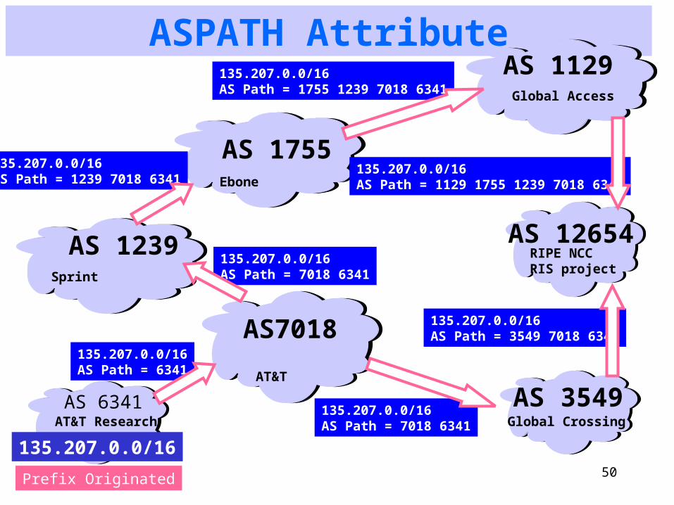
ASPATH Attribute
AS7018135.207.0.0/16AS Path = 6341
AS 1239Sprint
AS 1755Ebone
AT&T
AS 3549Global Crossing
135.207.0.0/16AS Path = 7018 6341
135.207.0.0/16AS Path = 3549 7018 6341
AS 6341
135.207.0.0/16
AT&T Research
Prefix Originated
AS 12654RIPE NCCRIS project
AS 1129Global Access
135.207.0.0/16AS Path = 7018 6341
135.207.0.0/16AS Path = 1239 7018 6341
135.207.0.0/16AS Path = 1755 1239 7018 6341
135.207.0.0/16AS Path = 1129 1755 1239 7018 6341

AS Graphs Do Not Show Topology!
The AS graphmay look like this. Reality may be closer to this…
BGP was designed to throw away information!
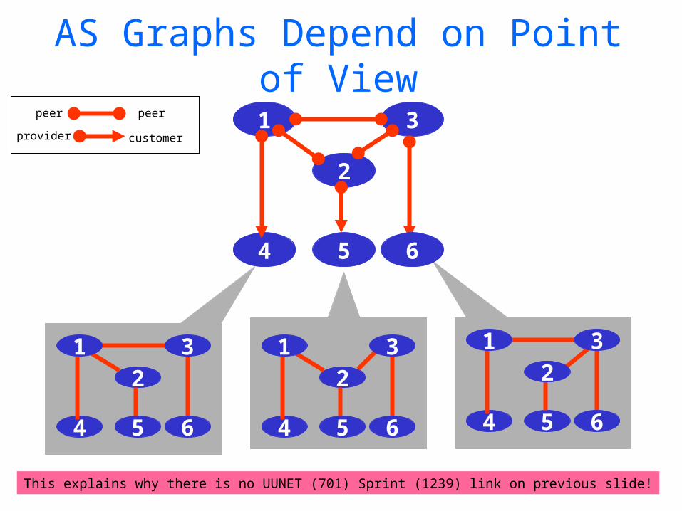
AS Graphs Depend on Point of View
This explains why there is no UUNET (701) Sprint (1239) link on previous slide!
peer peer
customerprovider
54
2
1 3
6
54
2
6
1 3
54 6
1 3
54
2
6
1 32

In fairness: could you do this “right” and still scale?Exporting internalstate would dramatically increase global instability and amount of routingstate
Shorter Doesn’t Always Mean Shorter
AS 4
AS 3
AS 2
AS 1
Mr. BGP says that path 4 1 is better than path 3 2 1
Duh!
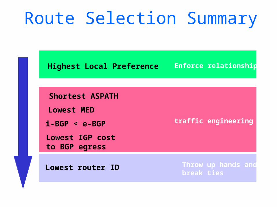
Route Selection Summary
Highest Local Preference
Shortest ASPATH
Lowest MED
i-BGP < e-BGP
Lowest IGP cost to BGP egress
Lowest router ID
traffic engineering
Enforce relationships
Throw up hands andbreak ties
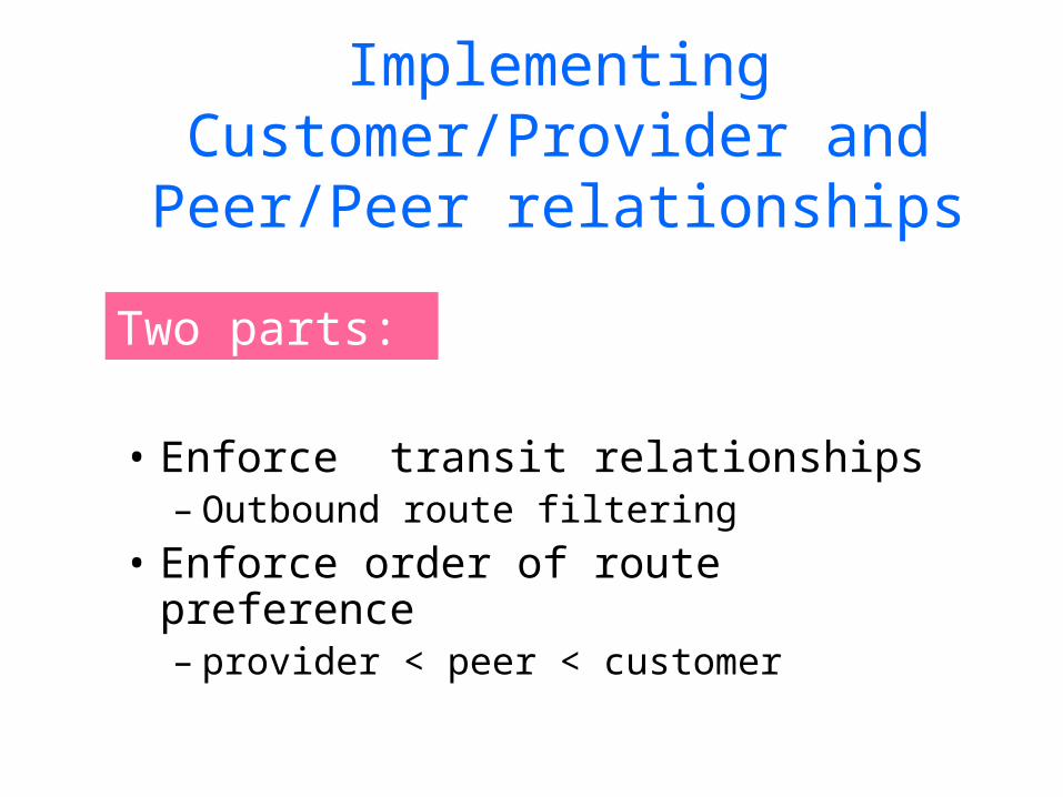
Implementing Customer/Provider and Peer/Peer relationships
• Enforce transit relationships – Outbound route filtering
• Enforce order of route preference– provider < peer < customer
Two parts:
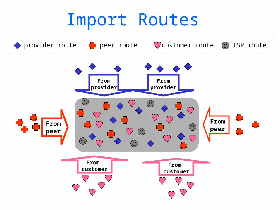
Import Routes
Frompeer
Frompeer
Fromprovider
Fromprovider
From customer
From customer
provider route customer routepeer route ISP route

Export Routes
Topeer
Topeer
Tocustomer
Tocustomer
Toprovider
From provider
provider route customer routepeer route ISP route
filtersblock

Why different Intra- and Inter-AS routing ? Policy: • Inter-AS: admin wants control over how its
traffic routed, who routes through its net. • Intra-AS: single admin, so no policy decisions
needed
Scale:• hierarchical routing saves table size, reduced
update trafficPerformance: • Intra-AS: can focus on performance• Inter-AS: policy may dominate over
performance
Today’s Lecture• Recap
– Addressing• IP Address• Sub-netting• Super-netting (CIDR)• Route Aggregation Examples
– Routing Protocols• Introduction• Intra-domain (RIP, OSPF)• Inter-domain (BGP)
• Multicast– Introduction – Internet Group Management Protocol (IGMP)– Routing Protocols
• Intra-domain (DVMRP, MOSPF, PIM)• Inter-domain (MSDP, SSM)
– Reliable Multicast
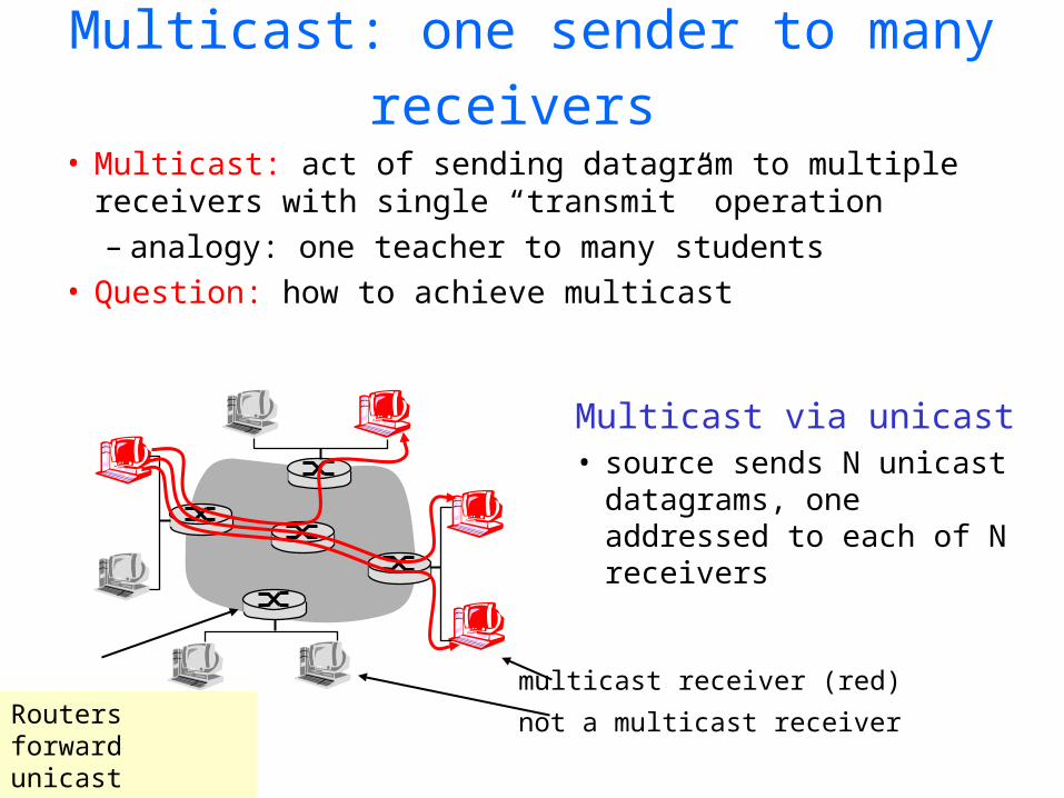
Multicast: one sender to many receivers
• Multicast: act of sending datagram to multiple receivers with single “transmit” operation– analogy: one teacher to many students
• Question: how to achieve multicast
Multicast via unicast• source sends N unicast
datagrams, one addressed to each of N receivers
multicast receiver (red)
not a multicast receiverRouters forward unicast datagrams
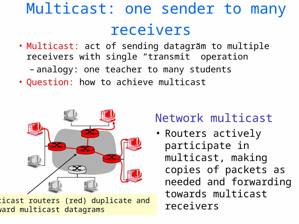
Multicast: one sender to many receivers
• Multicast: act of sending datagram to multiple receivers with single “transmit” operation– analogy: one teacher to many students
• Question: how to achieve multicast
Network multicast• Routers actively
participate in multicast, making copies of packets as needed and forwarding towards multicast receiversMulticast routers (red) duplicate and
forward multicast datagrams
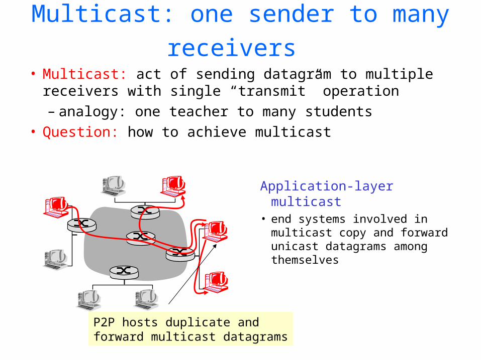
Multicast: one sender to many receivers
• Multicast: act of sending datagram to multiple receivers with single “transmit” operation– analogy: one teacher to many students
• Question: how to achieve multicast
Application-layer multicast• end systems involved in
multicast copy and forward unicast datagrams among themselves
P2P hosts duplicate and forward multicast datagrams

Internet Multicast Service Model
multicast group concept: use of indirection– host addresses IP datagram to multicast group– routers forward multicast datagrams to hosts
that have “joined” that multicast group
128.119.40.186
128.59.16.12
128.34.108.63
128.34.108.60
multicast group
226.17.30.197
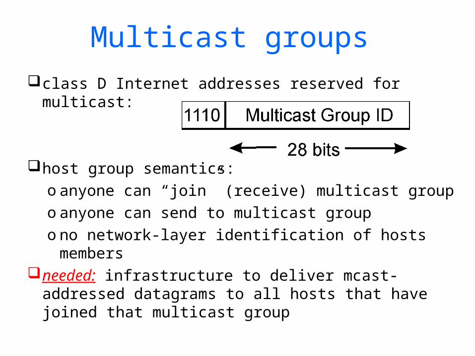
Multicast groupsclass D Internet addresses reserved for multicast:
host group semantics:o anyone can “join” (receive) multicast groupo anyone can send to multicast groupo no network-layer identification of hosts members
needed: infrastructure to deliver mcast-addressed datagrams to all hosts that have joined that multicast group
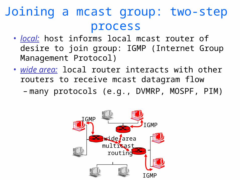
Joining a mcast group: two-step process
• local: host informs local mcast router of desire to join group: IGMP (Internet Group Management Protocol)
• wide area: local router interacts with other routers to receive mcast datagram flow– many protocols (e.g., DVMRP, MOSPF, PIM)
IGMPIGMP
IGMP
wide-areamulticast
routing
Today’s Lecture• Recap
– Addressing• IP Address• Sub-netting• Super-netting (CIDR)• Route Aggregation Examples
– Routing Protocols• Introduction• Intra-domain (RIP, OSPF)• Inter-domain (BGP)
• Multicast– Introduction – Internet Group Management Protocol (IGMP)– Routing Protocols
• Intra-domain (DVMRP, MOSPF, PIM)• Inter-domain (MSDP, SSM)
– Reliable Multicast

IGMP: Internet Group Management Protocol
• host: sends IGMP report when application joins mcast group– IP_ADD_MEMBERSHIP socket option– host need not explicitly “unjoin” group when
leaving • router: sends IGMP query at regular intervals
– host belonging to a mcast group must reply to query
query report
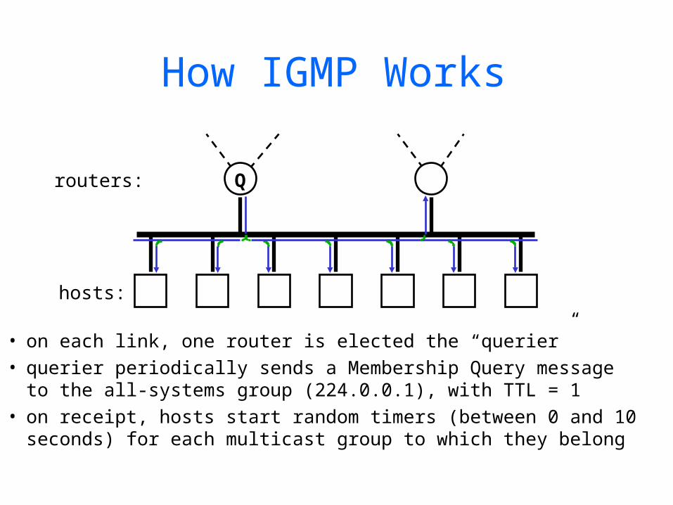
How IGMP Works
• on each link, one router is elected the “querier”• querier periodically sends a Membership Query message
to the all-systems group (224.0.0.1), with TTL = 1• on receipt, hosts start random timers (between 0 and 10
seconds) for each multicast group to which they belong
Qrouters:
hosts:

How IGMP Works (cont.)
• when a host’s timer for group G expires, it sends a Membership Report to group G, with TTL = 1
• other members of G hear the report and stop their timers• routers hear all reports, and time out non-responding groups
Q
G G G G

IGMPIGMP version 1• router: Host
Membership Query msg broadcast on LAN to all hosts
• host: Host Membership Report msg to indicate group membership– randomized delay
before responding– implicit leave via no
reply to Query
• RFC 1112
IGMP v2: additions include
• group-specific Query• Leave Group msg
– last host replying to Query can send explicit Leave Group msg
– router performs group-specific query to see if any hosts left in group
– RFC 2236
IGMP v3: – Join/Leave specific S in G– RFC 3376
Today’s Lecture• Recap
– Addressing• IP Address• Sub-netting• Super-netting (CIDR)• Route Aggregation Examples
– Routing Protocols• Introduction• Intra-domain (RIP, OSPF)• Inter-domain (BGP)
• Multicast– Introduction – Internet Group Management Protocol (IGMP)– Routing Protocols
• Intra-domain (DVMRP, MOSPF, PIM)• Inter-domain (MSDP, SSM)
– Reliable Multicast
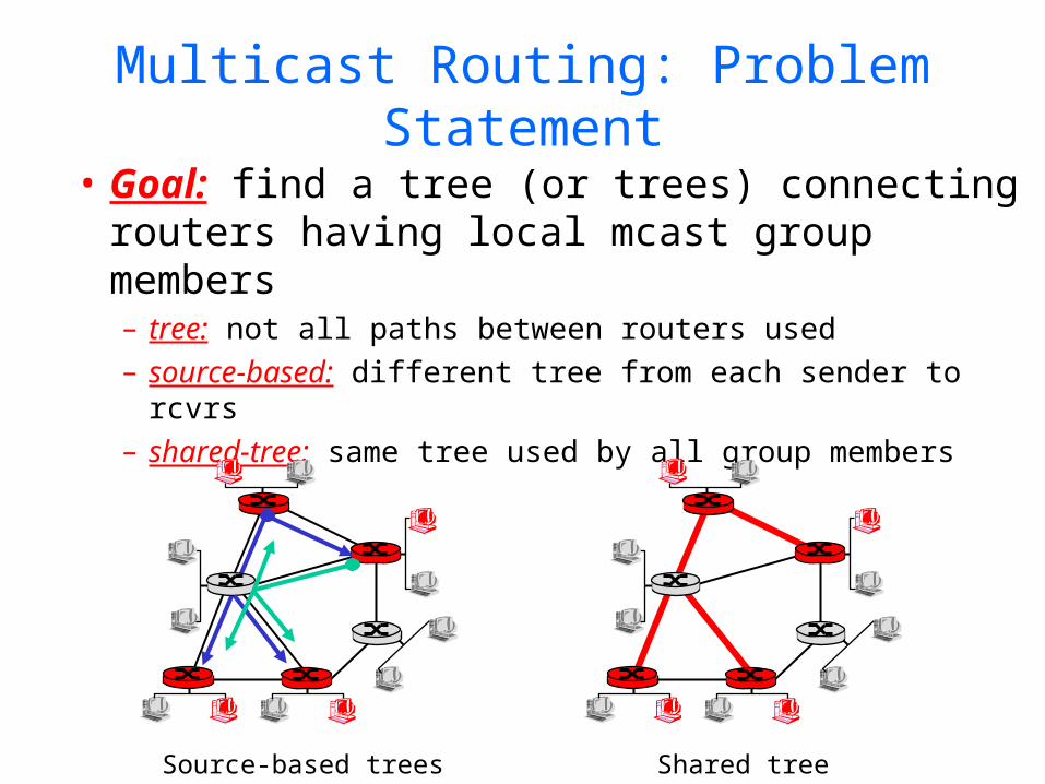
Multicast Routing: Problem Statement
• Goal: find a tree (or trees) connecting routers having local mcast group members – tree: not all paths between routers used– source-based: different tree from each sender to rcvrs– shared-tree: same tree used by all group members
Source-based trees Shared tree

Approaches for building mcast trees
Approaches:• source-based tree: one tree per source
– shortest path trees– reverse path forwarding
• group-shared tree: group uses one tree– minimal spanning (Steiner) – center-based trees
…we first look at basic approaches, then specific protocols adopting these approaches

Shortest Path Tree
• mcast forwarding tree: tree of shortest path routes from source to all receivers– Dijkstra’s algorithm
R1
R2
R3
R4
R5
R6 R7
21
6
3 4
5
i
router with attachedgroup member
router with no attachedgroup member
link used for forwarding,i indicates order linkadded by algorithm
LEGENDS: source
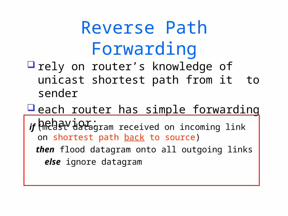
Reverse Path Forwarding
if (mcast datagram received on incoming link on shortest path back to source)
then flood datagram onto all outgoing links else ignore datagram
rely on router’s knowledge of unicast shortest path from it to sender
each router has simple forwarding behavior:

source
Building the Reverse Path

source
Building a Reverse Path Tree
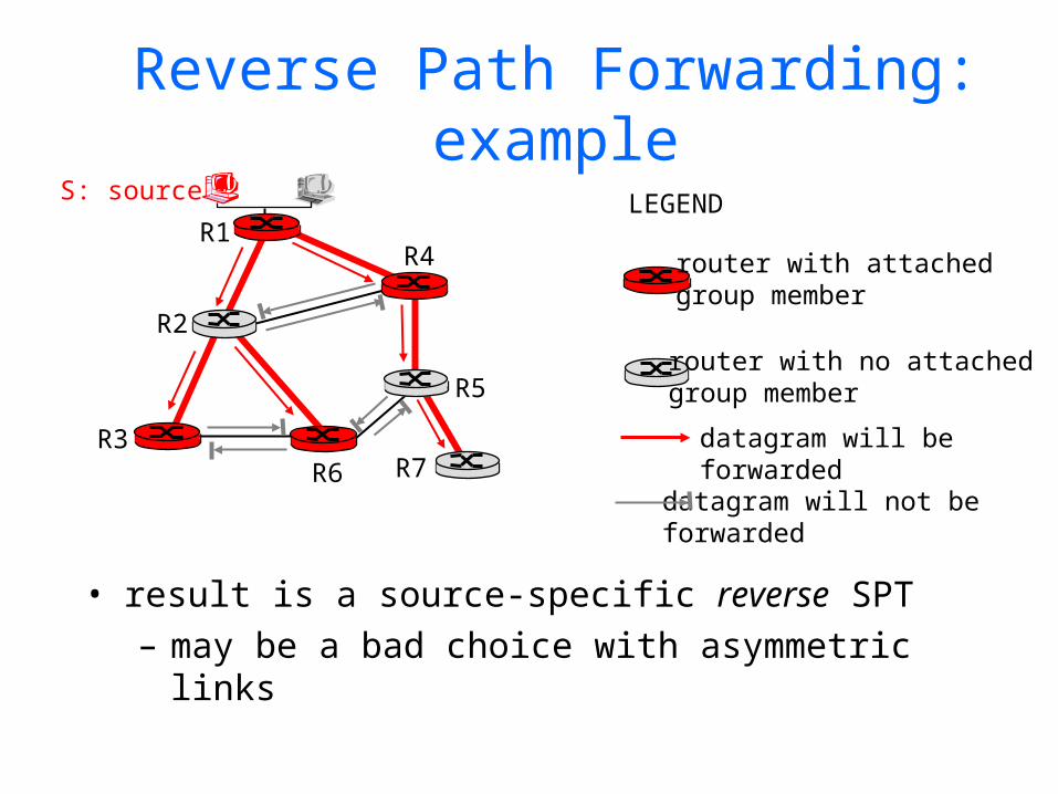
Reverse Path Forwarding: example
• result is a source-specific reverse SPT– may be a bad choice with asymmetric links
R1
R2
R3
R4
R5
R6 R7
router with attachedgroup member
router with no attachedgroup member
datagram will be forwarded
LEGENDS: source
datagram will not be forwarded
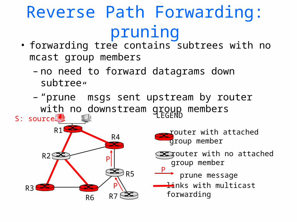
Reverse Path Forwarding: pruning• forwarding tree contains subtrees with no
mcast group members– no need to forward datagrams down subtree– “prune” msgs sent upstream by router with
no downstream group members
R1
R2
R3
R4
R5
R6 R7
router with attachedgroup member
router with no attachedgroup member
prune message
LEGENDS: source
links with multicastforwarding
P
P
P

Shared-Tree: Steiner Tree
• Steiner Tree: minimum cost tree connecting all routers with attached group members
• problem is NP-complete• excellent heuristics exists• not used in practice:
– computational complexity– information about entire network needed– monolithic: rerun whenever a router needs to
join/leave

Center-based trees• single delivery tree shared by all• one router identified as “center” of tree• to join:
– edge router sends unicast join-msg addressed to center router
– join-msg “processed” by intermediate routers and forwarded towards center
– join-msg either hits existing tree branch for this center, or arrives at center
– path taken by join-msg becomes new branch of tree for this router

Center-based trees: an example
Suppose R6 chosen as center:
R1
R2
R3
R4
R5
R6 R7
router with attachedgroup member
router with no attachedgroup member
path order in which join messages generated
LEGEND
21
3
1

Today’s Lecture• Recap
– Addressing• IP Address• Sub-netting• Super-netting (CIDR)• Route Aggregation Examples
– Routing Protocols• Introduction• Intra-domain (RIP, OSPF)• Inter-domain (BGP)
• Multicast– Introduction – Internet Group Management Protocol (IGMP)– Routing Protocols
• Intra-domain (DVMRP, MOSPF, PIM)• Inter-domain (MSDP, SSM)
– Reliable Multicast
The First Intra-Domain Routing Protocol:
DVMRP

Distance-Vector Multicast Routing Protocol (DVMRP)
DVMRP consists of two major components:(1)a conventional distance-vector routing protocol
(like RIP) which builds, in each router, a routing table like this:
(2) a protocol for determining how to forward multicast packets, based on the routing table and routing messages of (1)
subnet shortest dist via interface
a 1 i1
b 5 i1
c 3 i2… … …

Example Topology
g g
s
g

Phase 1: Truncated Broadcast
g g
s
g
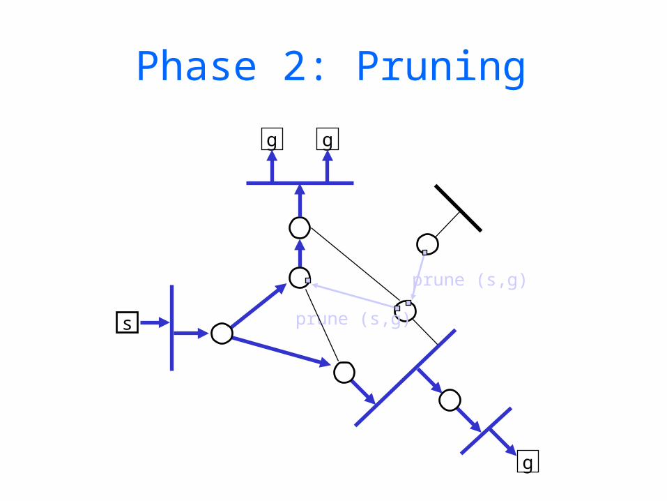
Phase 2: Pruning
g g
s
prune (s,g)
prune (s,g)
g

Steady State
g g
s
g
g

graft (s,g)
graft (s,g)
Grafting on New Receivers
g g
s
g
g
report (g)
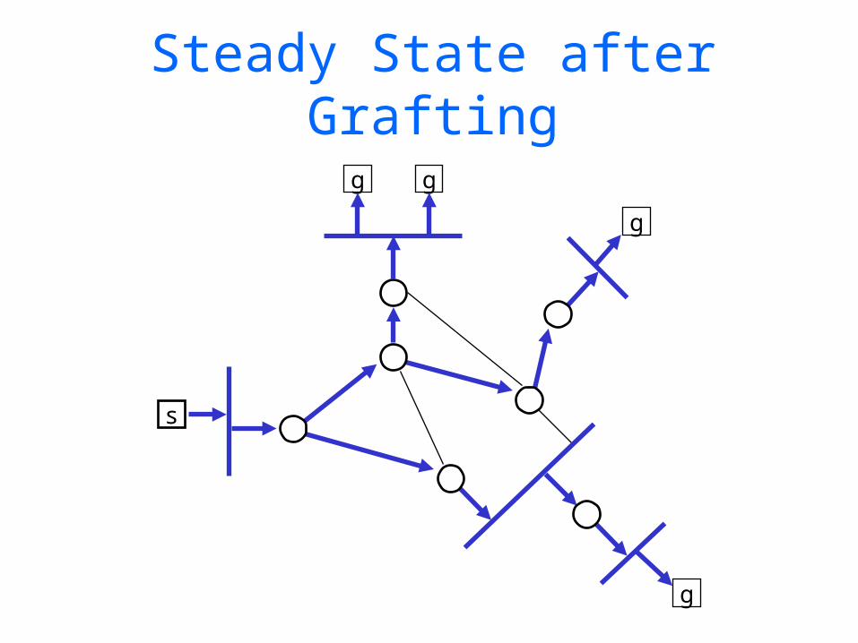
Steady State after Grafting
g g
s
g
g

Current IP Multicast Routing Protocols
DVMRP — Distance-Vector Multicast Routing Protocol
broadcast-and-prune,unidirectional per-source trees,builds own routing table
MOSPF — Multicast Extensions to Open Shortest-Path First Protocol
broadcast membership,unidirectional per-source trees,uses OSPF routing table
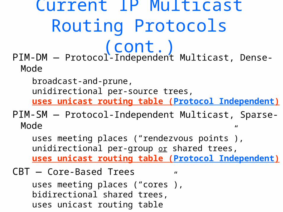
Current IP Multicast Routing Protocols (cont.)
PIM-DM — Protocol-Independent Multicast, Dense-Modebroadcast-and-prune,unidirectional per-source trees,uses unicast routing table (Protocol Independent)
PIM-SM — Protocol-Independent Multicast, Sparse-Modeuses meeting places (“rendezvous points”),unidirectional per-group or shared trees,uses unicast routing table (Protocol Independent)
CBT — Core-Based Treesuses meeting places (“cores”),bidirectional shared trees,uses unicast routing table
Multicast Routing: MOSPF

Multicast OSPF (MOSPF)
• an extension to OSPF (Open Shortest-Path First),a link-state, intra-domain routing protocolspecified in RFCs 1584 & 1585
• multicast-capable routers indicate that capability with a flag in their link-state messages
• routers include in their link-state messages a list of all groups that have members on the router’s directly-attached links (as learned through IGMP)

S1
R1
R2
X
Y
Link state: each router floods link-state advertisementMulticast: add membership information to “link state”
Each router then has a complete map of the topology, includingwhich links have members of which multicast groups
Z
S1
R1
R2
X
Y
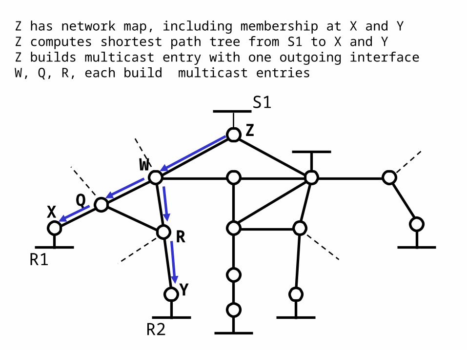
Z has network map, including membership at X and YZ computes shortest path tree from S1 to X and YZ builds multicast entry with one outgoing interfaceW, Q, R, each build multicast entries
Z
W
Q
R
R1
R2
X
Y
Z
W
Q
R
S1
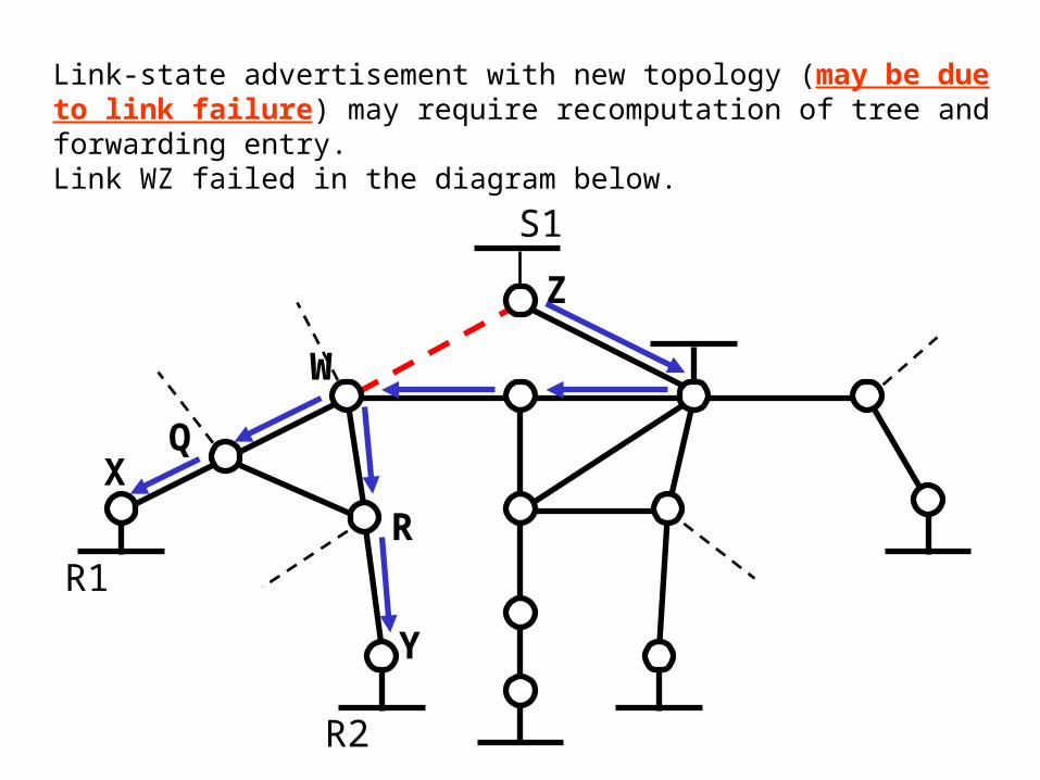
Link-state advertisement with new topology (may be due to link failure) may require recomputation of tree and forwarding entry.Link WZ failed in the diagram below.

R1
R2
X
Y
Z
W
Q
R
S1
T
R3
Link state advertisement (T) with new membership (R3) may require incremental computation and addition of interface to outgoing interface list (Z) (Similarly, disappearance of a membership may cause deletionan interface from an outgoing interface list). Link WZ is back to normal.

Multicast Routing: PIM
Protocol Independent Multicast (PIM)
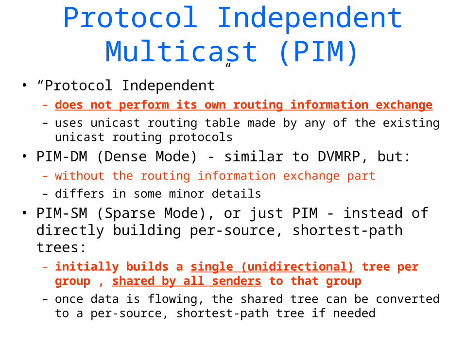
• “Protocol Independent”– does not perform its own routing information
exchange – uses unicast routing table made by any of the existing
unicast routing protocols
• PIM-DM (Dense Mode) - similar to DVMRP, but:– without the routing information exchange part– differs in some minor details
• PIM-SM (Sparse Mode), or just PIM - instead of directly building per-source, shortest-path trees:– initially builds a single (unidirectional) tree per group
, shared by all senders to that group – once data is flowing, the shared tree can be converted to a
per-source, shortest-path tree if needed

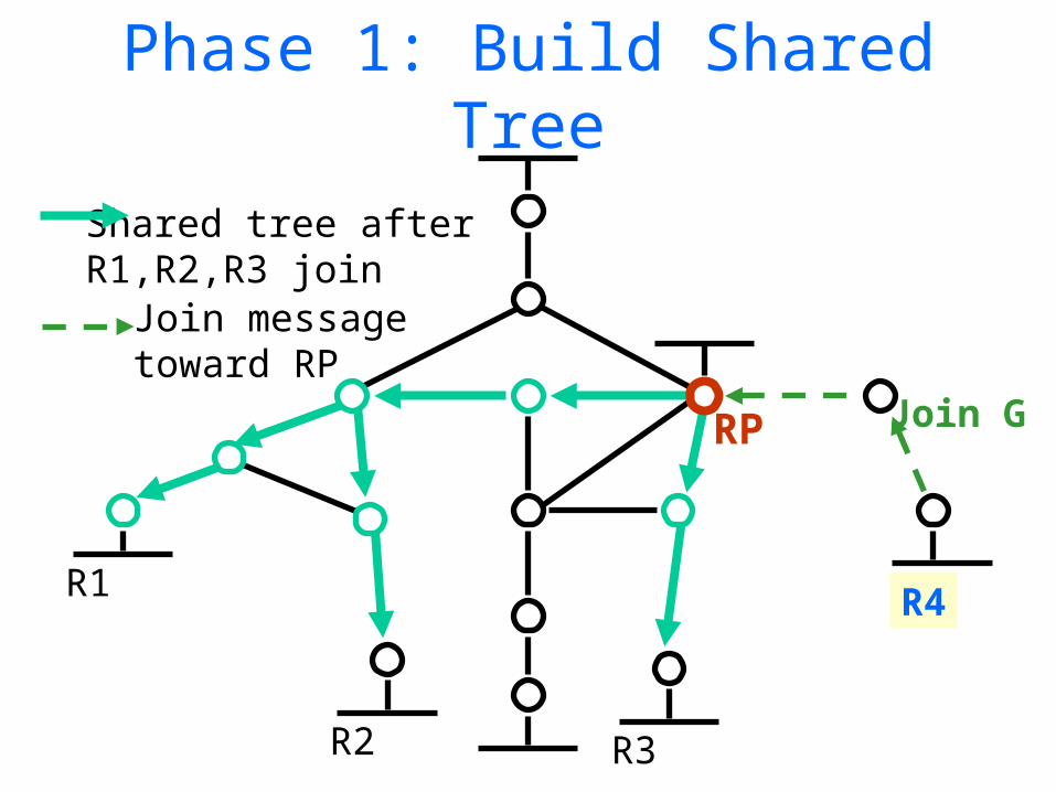
PIM Protocol Overview• Basic protocol steps
– routers with local members send Join messages towards a Rendezvous Point (RP) to join shared tree
– routers with local sources encapsulate data to RP
– routers with local members may initiate data-driven switch to source-specific, shortest-path tree
RP
R1
R2 R3
R4
Join messagetoward RP
Shared tree after R1,R2,R3 join
Phase 1: Build Shared Tree
Join G
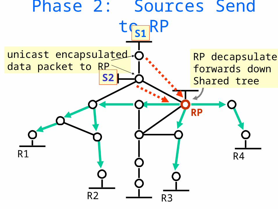
Phase 2: Sources Send to RP
RP
R1
R2 R3
R4
S1
unicast encapsulateddata packet to RP
RP decapsulates,forwards downShared treeS2

Phase 3: Stop Encapsulation
RP
R1
R2 R3
R4
S1
Join G for S1Join G for S2
S2
(S1,G)
(S1,G)
(*.G)
(S2,G)

Phase 4: Switch to Shortest Path Tree
R1
R2 R3
R4
Join messagestoward S2
shared tree
S1
S2
RP

Phase 5: Prune (S2 off) Shared Tree
R1
R2 R3
R4
S1
S2 distribution treeShared tree
Prune S2 off Shared tree where iif of S2 andRP entries differS2
RP
RP Mechanism
• end-systems only need multicast address to send or receive
• routers use algorithmic mapping of group address to RP from manageably-small set of RPs known throughout region
• consistent RP mapping and adaptation to failures is CRITICAL– all routers (within PIM region) must associate a
single active RP with a multicast group
• optimal RP location not necessary

RP Mechanisms — Overview
• Each candidate RP periodically indicates liveness to Bootstrap Router in the PIM region
• Bootstrap Router periodically distributes set of reachable candidate RPs to all PIM routers in region– like unicast routing—track liveness continuously, not
on demand
• Each PIM router uses the same hash function and set of RPs to map a particular multicast group address to that group’s RP.

Bootstrap Router
• Bootstrap Router function– construct set of RPs (RP set) based
on Candidate RP advertisements– periodically distribute RP set in
Bootstrap messages to all routers in region by hop-by-hop flooding
• Bootstrap Router should be well-connected for stability, and dynamically elected for robustness
Bootstrap Router Election
• simple bridge-like spanning-tree election algorithm
• candidate Bootstrap Routers originate PIM hop-by-hop Bootstrap messages with IP address and configurable preference value.
• Bootstrap messages exchanged by all PIM routers within region
• most preferred (or highest numbered) reachable candidate Bootstrap Router elected
• sent periodically and triggered

All routers use hash function to
map Group Address to RP• hash function
– input: group address G and address of each candidate RP in RP set (optional Mask)
– output: Value computed per candidate RP in RP set
– RP with highest value is the RP for G
• desirable characteristics– minimize remapping when RP reachability
changes — remap only those that lost RP– load spreading of groups across RPs

Today’s Lecture• Recap
– Addressing• IP Address• Sub-netting• Super-netting (CIDR)• Route Aggregation Examples
– Routing Protocols• Introduction• Intra-domain (RIP, OSPF)• Inter-domain (BGP)
• Multicast– Introduction – Internet Group Management Protocol (IGMP)– Routing Protocols
• Intra-domain (DVMRP, MOSPF, PIM)• Inter-domain (MSDP, SSM)
– Reliable Multicast
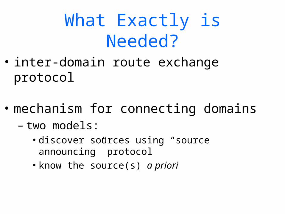
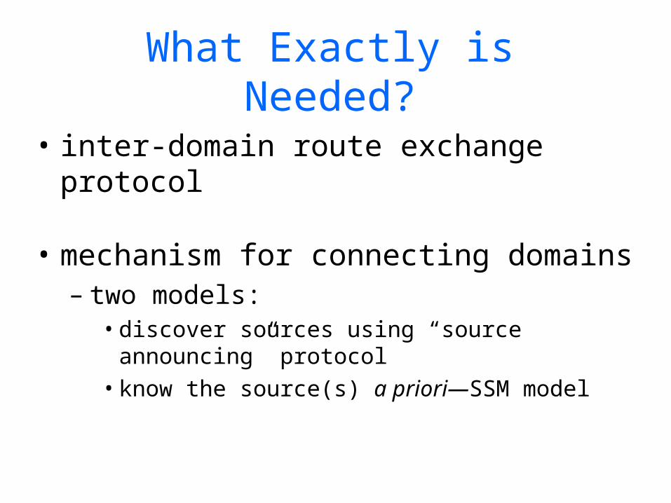
What Exactly is Needed?
• inter-domain route exchange protocol
• mechanism for connecting domains– two models:
• discover sources using “source announcing” protocol
• know the source(s) a priori

Inter-Domain Route Exchange
• Exchange multicast reachability between Autonomous Systems (AS)– Just like unicast routes are exchanged with BGP– Protocol is “Multiprotocol extensions to BGP” (RFC
2283)• Also known as “Multicast” BGP (MBGP)• Also known as BGP4+
• MBGP is available and deployed today.– Multiple vendors: Juniper, Cisco, Nortel, etc.

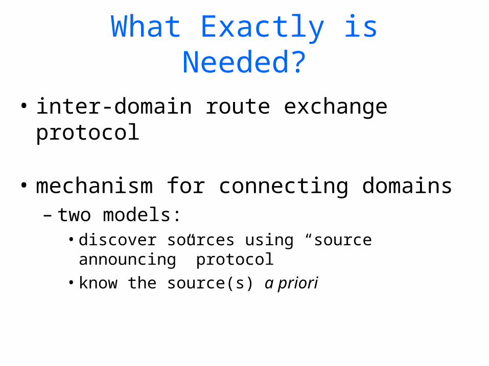
What Exactly is Needed?
• inter-domain route exchange protocol
• mechanism for connecting domains– two models:
• discover sources using “source announcing” protocol
• know the source(s) a priori

The Internet Solution
• Re-use existing protocols/solutions– Use PIM-SM in the inter-domain
• The challenge is to avoid “root dependencies”– A root/RP/core is one domain but no active
group participants (sources or receivers) in the domain
– Root dependencies can lead to political problems and inefficiencies

The Internet Solution (cont)
• The key: Establish a root/RP/core per domain– No “root dependencies”
• Remember the problem:– Connecting sources and receivers– Solution: Multicast Source Discovery Protocol
(MSDP)
• MSDP is the last piece of the puzzle; is simple to implement; and yields an interim solution to inter-domain multicast

MSDP -- Basic Idea
• MSDP advertises multicast sources to other domains
• Other domains decide if group members are active and find a way to get the data
• “MSDP connects shared-trees together”
• MSDP typically runs in the RP

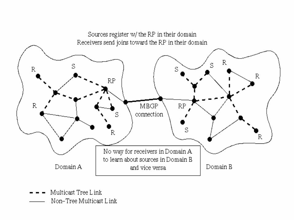
MSDP - Elements of Operation
• Receivers in a domain join the shared-tree
• The RP is known only to routers in the domain
• When a source goes active in a domain, it’s packets get to the RP in that domain
• The RP sends a Source-Active (SA) message identifying the source and group it sends to
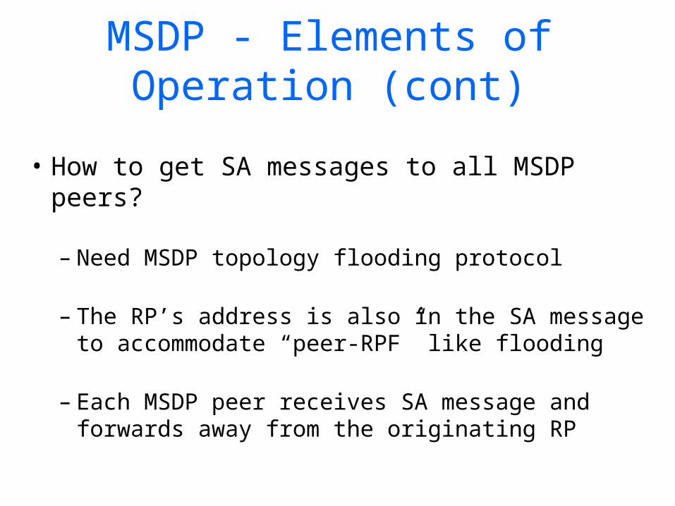
MSDP - Elements of Operation (cont)
• How to get SA messages to all MSDP peers?
– Need MSDP topology flooding protocol
– The RP’s address is also in the SA message to accommodate “peer-RPF” like flooding
– Each MSDP peer receives SA message and forwards away from the originating RP

MSDP - Elements of Operation (cont)
• Each MSDP speaking RP will examine SA message to see if any local members are joined to the group
• If so, the RP joins to source described in SA message
• Otherwise, the SA message is ignored (Flood-and-Join model)

How MSDP works with PIM-SM
RP
RP
RP
RP
MSDP peer
Physical link
A
B
C D
Receiver
Source
PIM message
MSDP message
SA
SA
SA
JoinJoinJoin
Join
Join
What Exactly is Needed?
• inter-domain route exchange protocol
• mechanism for connecting domains– two models:
• discover sources using “source announcing” protocol
• know the source(s) a priori—SSM model
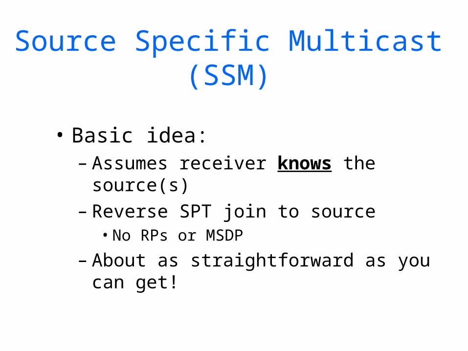
Source Specific Multicast (SSM)
• Basic idea:– Assumes receiver knows the
source(s)– Reverse SPT join to source
• No RPs or MSDP
– About as straightforward as you can get!
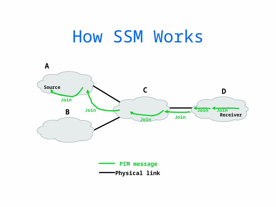
How SSM Works
Physical link
A
B
C D
Receiver
Source
PIM message
Join
JoinJoin
Join
Join
Join
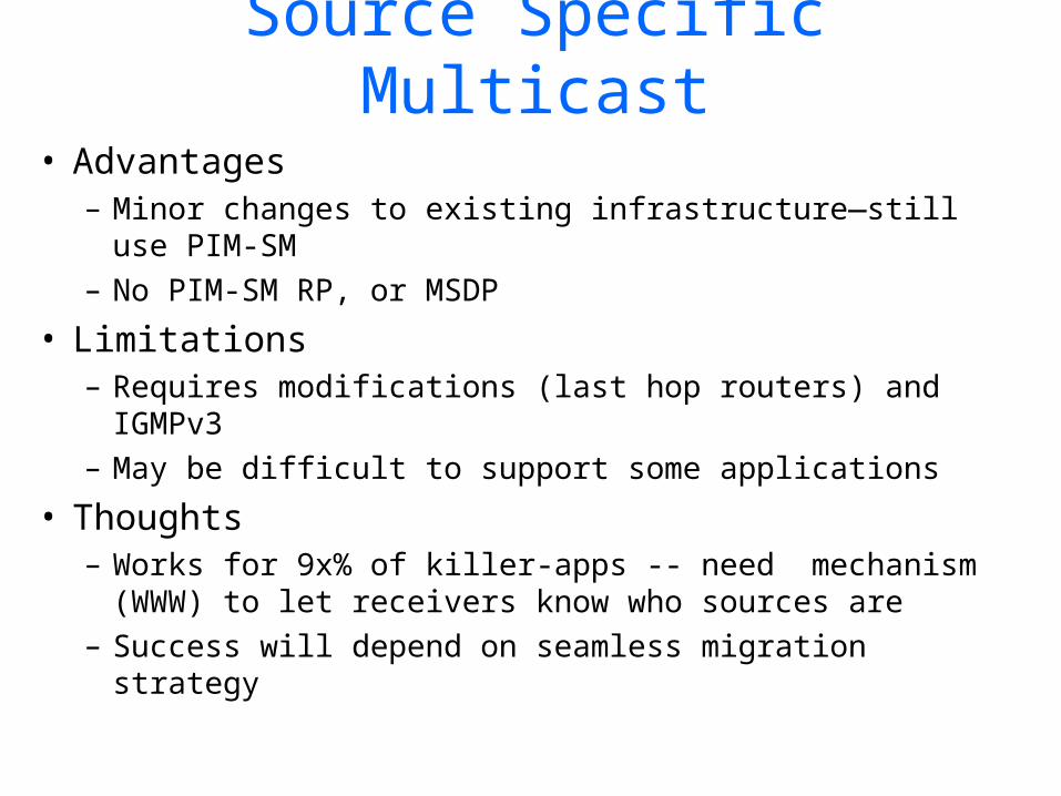
Source Specific Multicast
• Advantages– Minor changes to existing infrastructure—still use
PIM-SM– No PIM-SM RP, or MSDP
• Limitations– Requires modifications (last hop routers) and
IGMPv3– May be difficult to support some applications
• Thoughts– Works for 9x% of killer-apps -- need mechanism
(WWW) to let receivers know who sources are– Success will depend on seamless migration strategy
Today’s Lecture• Recap
– Addressing• IP Address• Sub-netting• Super-netting (CIDR)• Route Aggregation Examples
– Routing Protocols• Introduction• Intra-domain (RIP, OSPF)• Inter-domain (BGP)
• Multicast– Introduction – Internet Group Management Protocol (IGMP)– Routing Protocols
• Intra-domain (DVMRP, MOSPF, PIM)• Inter-domain (MSDP, SSM)
– Reliable Multicast

Fundamental Problems
• Scalable Reliable Multicast (SRM)
• Reliable Multicast Transport Protocol (RMTP)
• Forward Error Correction (FEC) and Reliable Multicast
• Pretty Good Multicast (PGM)
Reliable Multicast
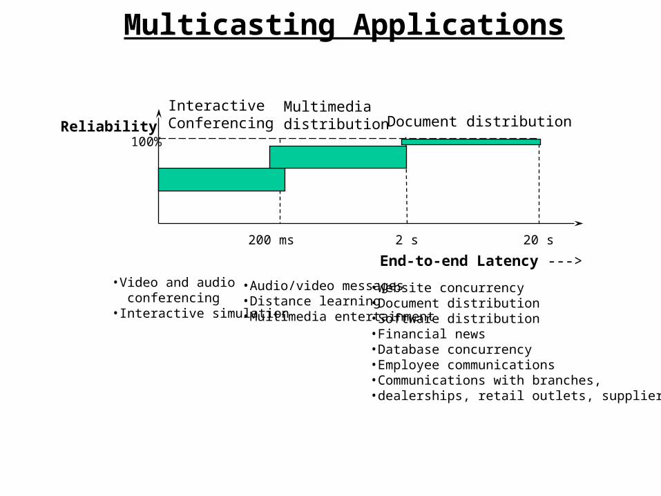
Reliability100%
200 ms 2 s 20 s
InteractiveConferencing
Multimediadistribution Document distribution
Multicasting Applications
•Audio/video messages •Distance learning•Multimedia entertainment
•Website concurrency•Document distribution•Software distribution•Financial news •Database concurrency•Employee communications•Communications with branches, •dealerships, retail outlets, suppliers
•Video and audio conferencing•Interactive simulation
End-to-end Latency --->

Reliable Multicast
• Enhancements to IP Multicast– Full Reliability (no packets lost)– Maximum reliability given a latency bound (some packets
may be lost)
IP IP Multicast
TCP UDP
Unicast Appl Multicast Appl
UDP
RMTP

Fundamental Problems
Acknowledgments
Acknowledgments
S = SenderR = Receiverrt = RouterS
rt
rt
rt
rt rt
rt
rt
rt rt
rt
R
rt
R
R R R R
R RR
• Ack-implosionAck-implosion– all receivers send ACK to
sender– sender becomes
bottleneck– increased end-to-end delay– reduced throughput
• Minimizing end-to-end latencyMinimizing end-to-end latency
• Flow/Congestion controlFlow/Congestion control
• ScalabilityScalability
Fundamental Problems
S
rt
rt
rt
rt rt
rt
rt
rt rt
rt
R
rt
R
R R R R
R RR
R
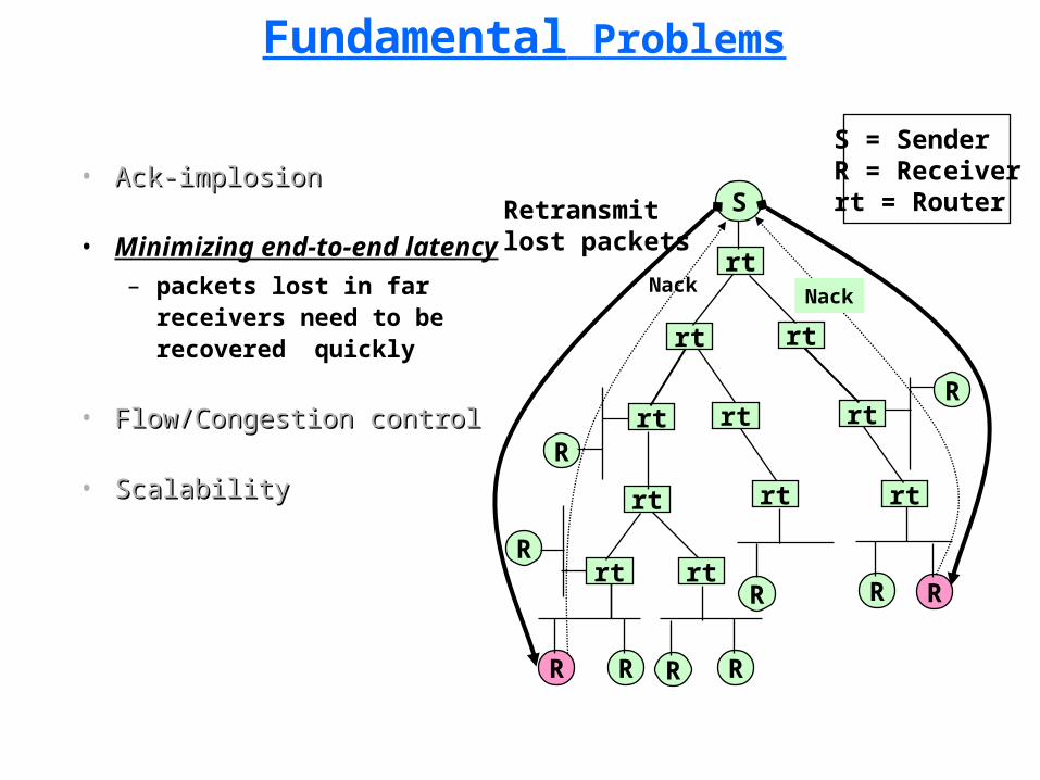
Retransmitlost packets
NackNack
S = SenderR = Receiverrt = Router
• Ack-implosionAck-implosion
• Minimizing end-to-end
latency– packets lost in far
receivers need to be recovered quickly
• Flow/Congestion controlFlow/Congestion control
• ScalabilityScalability
Fundamental Problems
S
rt
rt
rt
rt rt
rt
rt
rt rt
rt
R
rt
R
R R R R
R RR
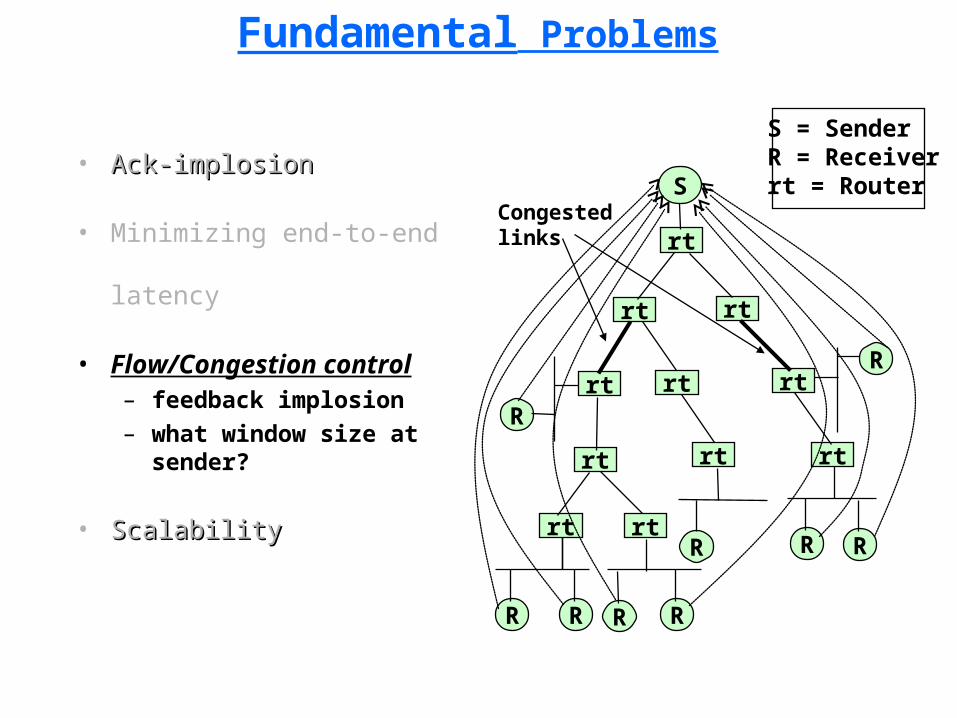
S = SenderR = Receiverrt = Router
• Ack-implosionAck-implosion
• Minimizing end-to-end
latency
• Flow/Congestion control– feedback implosion– what window size at
sender?
• ScalabilityScalability
Congestedlinks
• Fundamental Problems
Scalable Reliable Multicast (SRM)
• Reliable Multicast Transport Protocol (RMTP)
• Forward Error Correction (FEC) and Reliable Multicast
• Pretty Good Multicast (PGM)
Reliable Multicast
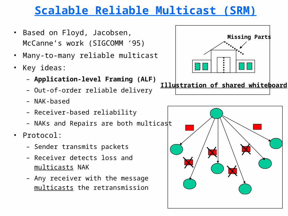
Scalable Reliable Multicast (SRM)
• Based on Floyd, Jacobsen, McCanne’s work (SIGCOMM ‘95)
• Many-to-many reliable multicast
• Key ideas:
– Application-level Framing (ALF)
– Out-of-order reliable delivery
– NAK-based
– Receiver-based reliability
– NAKs and Repairs are both multicast
• Protocol:
– Sender transmits packets
– Receiver detects loss and multicasts NAK
– Any receiver with the message multicasts the retransmission
Missing Parts
Illustration of shared whiteboard
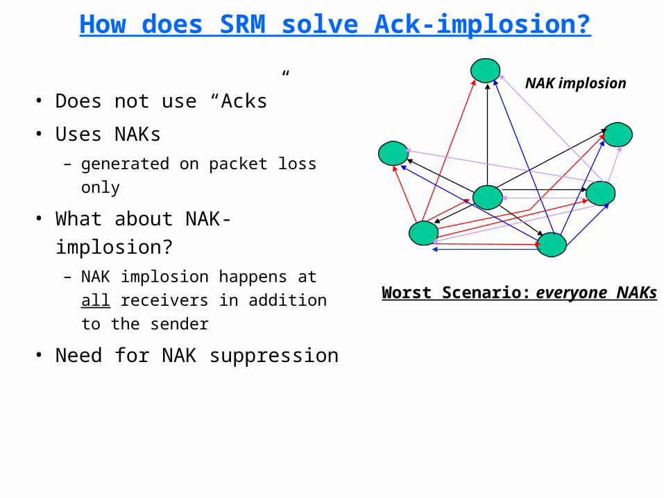
How does SRM solve Ack-implosion?
• Does not use “Acks”
• Uses NAKs – generated on packet loss only
• What about NAK-implosion?– NAK implosion happens at all
receivers in addition to the sender
• Need for NAK suppressionWorst Scenario: everyone NAKs
NAK implosion

Ideal NAK Suppression
Ideal Scenario: single NAK
NAKs
• Single NAK should suppress all others
• Randomly delay NAKs and shut up on receiving the same NAK
• How long should one wait before sending NAK?– Uniform distribution in the interval
[c1*ds,a, (c1+c2)*ds,a] where “s” is the
source of data and “a” is the receiver which missed a packet and ds,a is the
one-way delay between “s” and “a”.
• Each receiver needs one-way delay from every sender
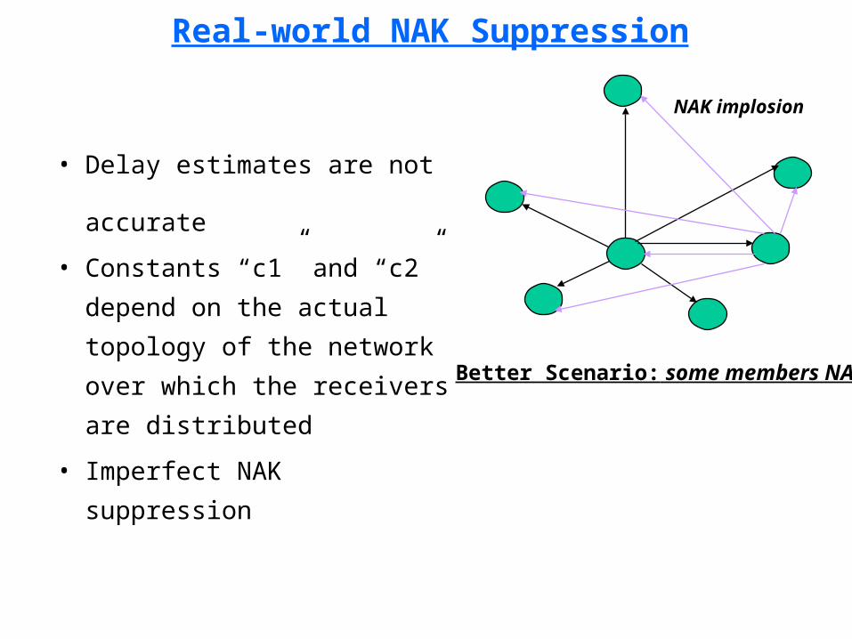
Real-world NAK Suppression
• Delay estimates are not
accurate
• Constants “c1” and “c2”
depend on the actual
topology of the network
over which the receivers
are distributed
• Imperfect NAK suppression
Better Scenario: some members NAK
NAK implosion

How does SRM reduce end-to-end latency?
• Any receiver with the repair packet can do the multicast retransmission
• May lead to “repair implosion” – repair implosion happens at
all receivers in addition to the sender
• Need for repair suppression
Worst Scenario: everyone sends REPAIR
REPAIR implosion

Ideal Repair Suppression
• Single “repair” should suppress all
others
• Schedule repair timers and retransmit when timer expires unless someone has already done the retransmission.
• How long should one wait before sending repair?– Uniform distribution in the interval []
d1*da,b, (d1+d2)*da,b where “a” is the
NAK generator and “b” is a receiver with the repair packet and da,b is the one-way delay from “b” to “a”.
• Each receiver needs one-way delay from every other receiver
Ideal Scenario: single REPAIR
REPAIRs

Real-world Repair Suppression
• Delay estimates are not
accurate
• Constants “d1” and “d2”
depend on the actual
topology of the network
over which the receivers
are distributed
• Imperfect “repair”
suppression
Better Scenario: some send REPAIR
REPAIR implosion
Scalability of SRM
Self-organization of receivers
REPAIR implosion
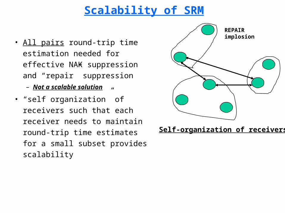
• All pairs round-trip time estimation needed for effective NAK suppression and “repair” suppression– Not a scalable solution
• “self organization” of receivers such that each receiver needs to maintain round-trip time estimates for a small subset provides scalability

• Fundamental Problems
• Scalable Reliable Multicast (SRM)
Reliable Multicast Transport Protocol (RMTP)
• Forward Error Correction (FEC) and Reliable Multicast
• Pretty Good Multicast (PGM)
Reliable Multicast

Reliable Multicast Transport Protocol (RMTP)
• Groups receivers into “local regions” with a DR in each region
• Organizes the DRs in a logical
hierarchy
• Transmission by Sender
• Acks from R to DR
• Acks from DR to S or DR
• Retransmission by DR
S
rt
rt
rt
rt rt
rt
rt
rt rt
rt
DR
rt
DR
R R R
R R RR
Acknowledgments
Acknowledgments
DR
R
DR
D D
D DD
D D D
DD
D D
D D
S = SenderR = Receiverrt = Router
DR = Designated Receiver
How does RMTP solve Ack-implosion?
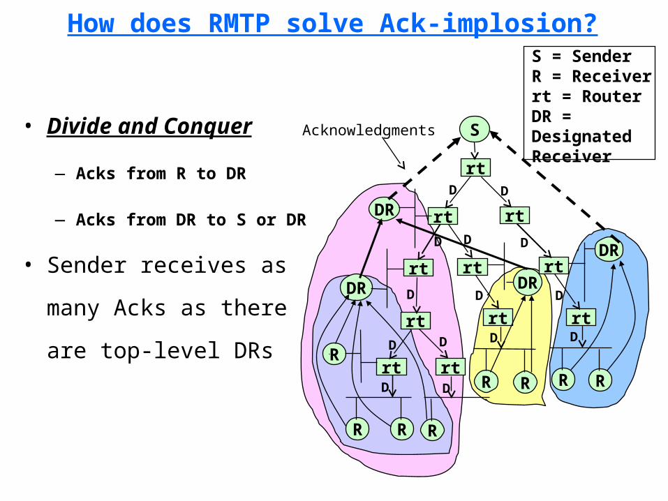
• Divide and Conquer
— Acks from R to DR
— Acks from DR to S or DR
• Sender receives as
many Acks as there
are top-level DRs
S
rt
rt
rt
rt rt
rt
rt
rt rt
rt
DR
rt
DR
R R R
R R RR
Acknowledgments
DR
R
DR
D D
D DD
D D D
DD
D D
D D
S = SenderR = Receiverrt = RouterDR = DesignatedReceiver
How does RMTP minimize end-to-end latency?
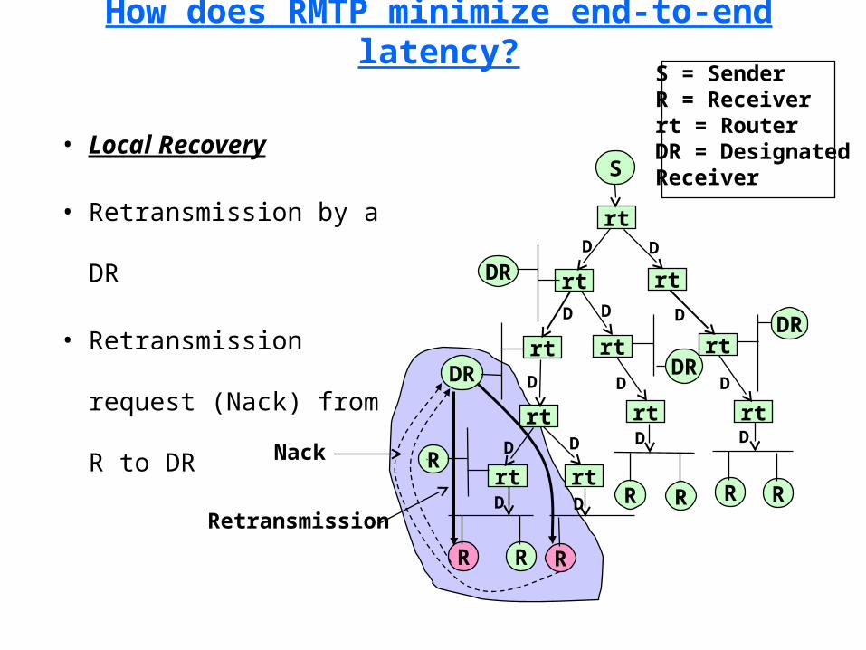
• Local Recovery
• Retransmission by a
DR
• Retransmission
request (Nack) from R
to DR
S
rt
rt
rt
rt rt
rt
rt
rt rt
rt
DR
rt
DR
R R R
R R RR
DR
R
DR
D D
D DD
D D D
DD
D D
D DNack
Retransmission
S = SenderR = Receiverrt = RouterDR = DesignatedReceiver

Recovery Strategy and Robustness of RMTP
• Receivers switch to
next-level DR if current
DR fails
• Primary and Backup
Sender
S
rt
rt
rt
rt rt
rt
rt
rt rt
rt
DR
rt
DR
R R R
R R RR
Acknowledgments
DR
R
DR
D D
D DD
D D D
DD
D D
D D
S = SenderR = Receiverrt = RouterDR = DesignatedReceiver
DR Failure

Scalability of RMTP
• RMTP is scalable because
of:
– hierarchical organization
– “local regions” can be split
to accommodate more
receivers
– local recovery keeps end-
to-end latency low
regardless of group size
• One caveat:
– how do you construct the
“logical tree”
automatically?
S
rt
rt
rt
rt rt
rt
rt
rt rt
rt
DR
rt
DR
R R R
R R RR
DR
R
DR
D D
D DD
D D D
DD
D D
D D
S = SenderR = Receiverrt = RouterDR = DesignatedReceiver
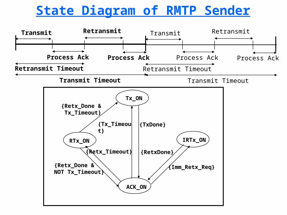
State Diagram of RMTP Sender
Transmit
Process Ack
Retransmit
Process Ack
Retransmit Timeout
Transmit Timeout
Transmit
Process Ack
Retransmit
Process Ack
Retransmit Timeout
Transmit Timeout
Tx_ON
RTx_ON IRTx_ON
ACK_ON
{Tx_Timeout}
{TxDone}
{RetxDone}
{Imm_Retx_Req}{Retx_Done &NOT Tx_Timeout}
{Retx_Timeout}
{Retx_Done & Tx_Timeout}
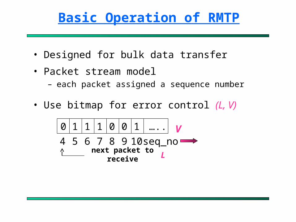
Basic Operation of RMTP
• Designed for bulk data transfer
• Packet stream model– each packet assigned a sequence number
• Use bitmap for error control (L, V)
0 1 111 0 0 …..
4 85 6 7 9 10 seq_nonext packet to receive
V
L

Basic Operation of RMTP
• Send packets at fixed intervals (t_send)• Upper bound for sending rate:
Time
t_send
packets
max. rate = (packet_size * send_win) / t_send

Example to Illustrate RMTP Execution
Send Window = 16, Mcast_Thresh = 1S
R1
R2
R3
1, . . ., 16Retransmit (8,10)
Retransmit (5,10)
Retransmit (8,14)
R3 R1, R2 R2, R3 R1
1 2 2 1
14 10 8 5 Packet#
# of Retransmission Request
Address of Requesting Receivers
1 2 3 4 5 6 7 8 9 10 11 12 13 14 15 16
Avail_window
ReXmitQueue
SendWindow
Slide Window
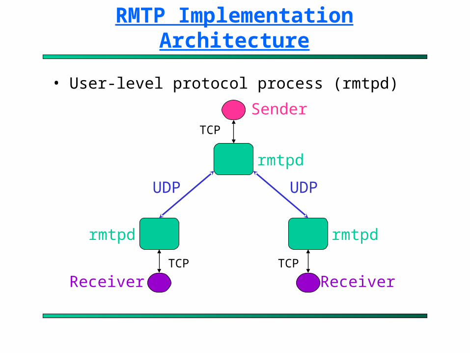
RMTP Implementation Architecture
• User-level protocol process (rmtpd)
ReceiverReceiver
Sender
UDP UDP
rmtpdrmtpd
rmtpd
TCP
TCP TCP

Reliable Multicasting of a File
Application Data Unit (ADU) < ADU size
Application feeding RMTP daemon
t = 0
T_dally< T_dally
Retransmission RequestResets T_dally Timer
Application Data Unit Application Data Unit
Time
Application feeds equal-sized data units to RMTP daemon except for the last chunk
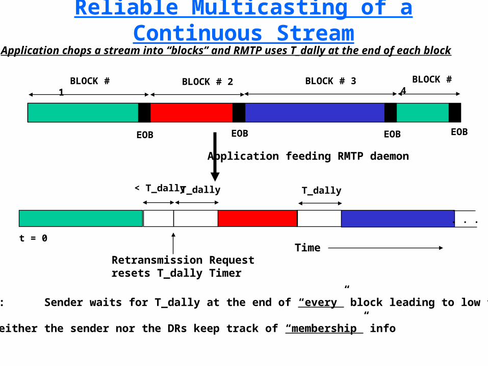
Reliable Multicasting of a Continuous Stream
BLOCK # 1
Application feeding RMTP daemon
t = 0
< T_dally T_dally T_dally
BLOCK # 2 BLOCK # 3 BLOCK # 4
Time Retransmission Requestresets T_dally Timer
. . .
EOB EOB EOB EOB
DRAWBACK: Sender waits for T_dally at the end of “every” block leading to low throughput
WHY? Neither the sender nor the DRs keep track of “membership” info
Application chops a stream into “blocks” and RMTP uses T_dally at the end of each block

Reliable Multicasting of a Continuous Stream
BLOCK # 1
Application feeding RMTP daemon
t = 0
BLOCK # 2 BLOCK # 3 BLOCK # 4
EOB EOB EOB EOB
DRAWBACK: Additional processing at Sender and DRs
ADVANTAGE: High throughput
Wait for ACKfrom “all” children
Wait for ACKfrom “all” children
Wait for ACKfrom “all” children
Sender and DRs explicitly keep track of their children in a dynamic manner
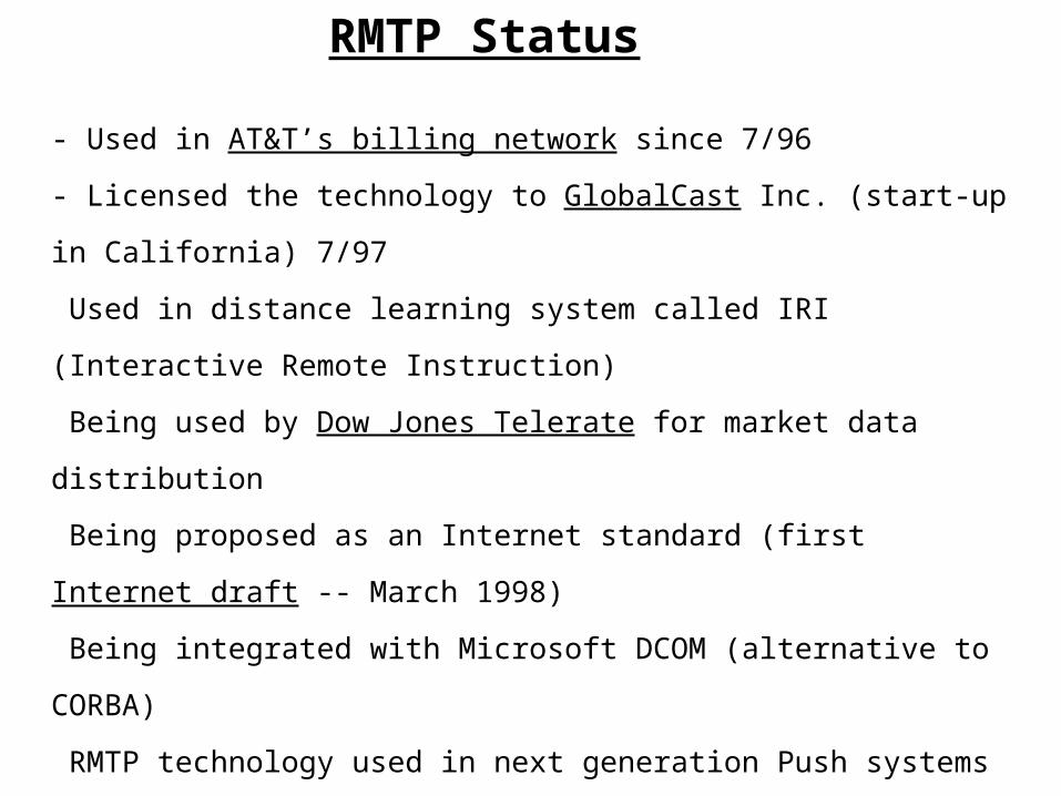
RMTP Status
- Used in AT&T’s billing network since 7/96
- Licensed the technology to GlobalCast Inc. (start-up in California) 7/97
Used in distance learning system called IRI (Interactive Remote Instruction)
Being used by Dow Jones Telerate for market data distribution
Being proposed as an Internet standard (first Internet draft -- March 1998)
Being integrated with Microsoft DCOM (alternative to CORBA)
RMTP technology used in next generation Push systems
RMTP used in Web Caching solution from Lucent Technologies (IPWorX)

• Fundamental Problems
• Scalable Reliable Multicast (SRM)
• Reliable Multicast Transport Protocol (RMTP)
Forward Error Correction (FEC) and Reliable Multicast
• Pretty Good Multicast (PGM)
Reliable Multicast

Forward Error Correction and Reliable Multicast
Transmission
• Nonnenmacher, Biersack and Towsley in SIGCOMM’97 showed
how reliable multicast can be made scalable by incorporating
forward error correction (FEC)
• Key idea:
– proactively send parity packets with regular data packets
– loss of limited number of packets can be recovered using the
redundant packets
– reduces retransmissions
– improves latency (useful for delay-sensitive traffic)
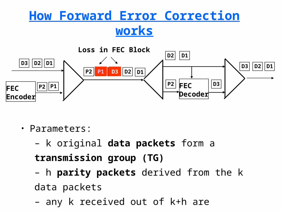
How Forward Error Correction works
• Parameters:
– k original data packets form a transmission group (TG)
– h parity packets derived from the k data packets
– any k received out of k+h are sufficient
FECEncoder
D2 D1D3
P1P2
D2 D1D3P1P2
FECDecoder
P2 D3
D2 D1Loss in FEC Block
D2 D1D3

Why FEC for Reliable Multicast
• A single parity packet can repair the loss of different data
packets at different receivers
S
R1
R2
R3D2 D1D3
D2 D1D3
D2 D1D3
S
R1
R2
R3D2 D1D3
D2 D1D3
D2 D1D3
S
R1
R2
R3 P
First Transmission
Data Retransmission
Parity Retransmission
P
PP = D1 xor D2 xor D3

Where to put FEC?
Application
RM
FEC
Network
Data Link
Application
RM/FEC
Network
Data Link
Layered FEC Integrated FEC
RM: Reliable Multicast

Integrated FEC
• At Sender:
– Send k original packets
• At Receiver:
– If k-l packets (l > 0) have been received, send NAK(l)
requesting l parities
• At Sender:
– Receive NAK(L1), NAK(L2), …, NAK(LR) from the receivers
– Send Lmax = max{L1, L2, …, LR} parity packets
Cost of FEC Computation
• Network benefits from reduced number of transmissions
due to integrated FEC
� But FEC is not for free
• Processing cost
– How fast can the coding/decoding be done?
– What is the throughput of a protocol based on integrated FEC?

Summary of FEC & RM
• Integrated FEC
– dramatically reduces the number of transmissions
– achieves scalability for large number of receivers (up to 10^6)
– reduces the feedback
• Software FEC for Reliable Multicast is feasible today
• From Nonnenmacher:
¬ FEC is like a wonder under the Christmas tree:
� All children missing different packets are satisfied with a
single common packet
Multicast Layered Recovery (MLR)
• Rhee et.al. At NCSU
• Nonnemacher et.al. Show that FEC+RM induces much less total
traffic compared to retransmission alone
• Question: How many repair packets should be sent?
¬ Worst case receivers?
– Introduces repair locality problem
• Solution: MLR suggests sending FEC packets in multiple layers

Multicast Layered Recovery (MLR)
• Partitions f FEC repair
packets into K groups: F = {1,
2,…,K}
• Transmits each group i using
a different multicast address
• Receivers join or leave multicast groups to match their loss rates
Data FEC repairs
G0
G1
G2
G3
• Fundamental Problems
• Scalable Reliable Multicast (SRM)
• Reliable Multicast Transport Protocol (RMTP)
• Forward Error Correction (FEC) and Reliable Multicast
Pretty Good Multicast (PGM)
Reliable Multicast
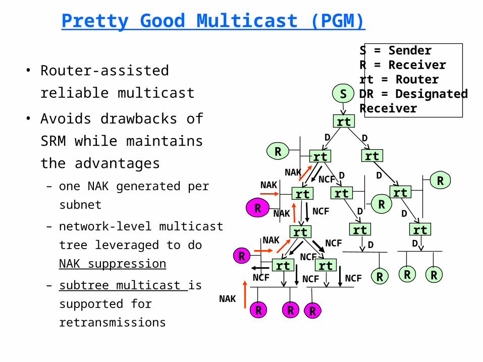
Pretty Good Multicast (PGM)
• Router-assisted reliable
multicast
• Avoids drawbacks of
SRM while maintains the
advantages
– one NAK generated per
subnet
– network-level multicast
tree leveraged to do NAK
suppression
– subtree multicast is
supported for
retransmissions
S
rt
rt
rt
rt rt
rt
rt
rt rt
rt
R
rt
R
R R R
R R R
R
R
R
D D
D
D
D
S = SenderR = Receiverrt = RouterDR = DesignatedReceiver
NAK
NCF
NAK
NCF
NAK NCF
NAKNCFD
D
D
NCF
NCF
NCF
NAK

Pretty Good Multicast (PGM)
• Subtree multicast from
Designated Local
Retransmitter (DLR)
– minimal redundant
retransmissions
– router maintains per lost
packet state
S
rt
rt
rt
rt rt
rt
rt
rt rt
rt
R
rt
R
R R R
R R R
R
R
R
D D
D
D
D
S = SenderR = Receiverrt = RouterDR = DesignatedReceiver
D
D
D
DLR
Retransmissions
• One size does not fit all
• SRM with self-organization + local recovery is best suited for
many-to-many applications
• RMTP is good for one-to-many reliable multicast applications
• FEC is a powerful mechanism which can be combined with either
SRM or RMTP to further improve scalability and efficiency
• Pretty Good Multicast (PGM) leverages state maintained in the
routers to improve the efficiency of reliable multicast protocols
Summary of Reliable Multicast
• Books:
– Multicasting on the Internet and its Applications by Sanjoy Paul (Kluwer Academic Publisher)
• Urls:
– http://catarina.usc.edu/multicast/srm.html
– http://www.east.isi.edu/RMRG/
– http://www.tascnets.com/mist/doc/mcpCompare.html
– http://research.ivv.nasa.gov/RMP/links.html
– http://info.internet.isi.edu:80/in-notes/rfc/files/rfc1889.txt
– http://info.internet.isi.edu:80/in-notes/rfc/files/rfc2326.txt
– http://www.eurecom.fr/~erbi/Bib/bib.html
Useful References

How to Dig Deeper
• ftp://ftpeng.cisco.com/ipmulticast/– directory of lots of useful documents
• briefings, guides, tutorials, command descriptions• recommended configurations and settings• interoperability notes, deployment strategies (ATM)
• http://www.cisco.com/warp/public/732/multicast/
• 3Com info: do site search– http://www.3com.com/nsc/501303.html (Maufer
book)
Multicast Textbooks
• Beau Williamson, Developing IP Multicast Networks (The Cisco Press Design and Implementation Series), 2000.
• Sanjoy Paul, Multicasting on the Internet and its Applications, (Kluwer Academic Publishers), 1998
• Tom Maufer, Deploying IP Multicast in the Enterprise, Prentice Hall, 1997.
• Ken Miller, Multicast Networking and Applications, Addison Wesley, 1998.


![Moore's Law Statistical Validation [Updated] - Sanjoy Sanyal](https://static.fdocuments.in/doc/165x107/5455d6e9af795940578b51a3/moores-law-statistical-validation-updated-sanjoy-sanyal.jpg)