ECC Report 173 - EETT · CCDP Co-Channel Dual-Polarization CEPT European Conference of Postal and...
73
Fixed Service in Europe Current use and future trends post 2011 March 2012 ECC Report 173
Transcript of ECC Report 173 - EETT · CCDP Co-Channel Dual-Polarization CEPT European Conference of Postal and...

Fixed Service in Europe
Current use and future trends post 2011
March 2012
ECC Report 173

ECC REPORT 173 – Page 2
0 EXECUTIVE SUMMARY
The Fixed Service is and remains a key service for telecommunication infrastructure development. Since 1997, the CEPT has provided public information to present a picture of the FS deployment in Europe with the intention to use it as a reference and for guidance purposes for administrations, operators and manufacturers.
In 2010, the ECC decided to start the edition of a new report as an updated version of the ECC Report 003 (published in 2002), in order to verify the assumptions of the previous studies and to collect updated information on the number of fixed links for each band in CEPT countries. Therefore, this report builds on the results of the original ERO Reports on FS trends post-1998 and post-2002 by revising it and updating the information on FS use.
Developments in the technologies show the new trends in the FS sectors: ranging from higher modulation schemes (up to 1024 levels), adaptive modulation schemes to Hybrid/Ethernet technology equipment, better suited for different Quality of Service (QoS) levels and high capacity links. Fixed Wireless Access (FWA) applications are either stable/decreasing in higher frequency bands or migrating to converged Broadband Wireless Access (BWA) applications networks in bands at around 3.5 GHz or below. The information gathered for developing this report gives the evidence that the current trends in the FS market place are for an ever increasing provision of high bandwidth capacity for the mobile networks infrastructures. These very high capacity links are able to provide a viable alternative to deploying fibre optic especially in rural areas but equally in high density urban areas where there would be severe disruption caused by digging up roads etc. to lay down fibres. As a consequence the report highlights the strategic importance of some frequency bands for the FS. Some of these bands have already started to show a rapid growth in terms of number of links (13 GHz, 15 GHz, 18 GHz, 23 GHz, 38 GHz), and on which special attention from administrations should be taken; while others are still preparing to take off (32 GHz, 50 GHz, 70/80 GHz, 92 GHz). In addition, the potentially interesting issue of NLOS urban backhauling for the new generation of mobile networks might open for new applications also in FS bands below about 6 GHz. This report highlights also the fact that the CEPT proactively responds to the industry demand for efficient usage in the new millimetric wave bands with a set of new or revised recommendations. In term it creates a healthy competitive FS environment with wider harmonisation use of FS. As part of the development strategies, the CEPT, in 2011, revised the recommendation on the usage of the band 7125-8500 MHz with a view to harmonise its use in Europe for countries that are in a position to refarm, as it is the only FS band lacking harmonisation incentives (in terms of clear CEPT policy and/or channel arrangements). Regarding the assignment procedures used, the responses show that for P-P links the most used method foresees conventional link-by-link license and centralised coordination. However, assignment/auction of frequency blocks in certain bands becomes also popular; this is particularly true when also P-MP (or, in some cases, even mixed FS and other telecommunication service) are permitted.

ECC REPORT 173 – Page 3
TABLE OF CONTENTS
0 EXECUTIVE SUMMARY ............................................................................................................................ 2
1 INTRODUCTION ......................................................................................................................................... 8 1.1 Background to the study .................................................................................................................... 8 1.2 Objective of the study ........................................................................................................................ 8 1.3 Methodology ...................................................................................................................................... 8 1.4 Contributions to the study .................................................................................................................. 8
2 DEFINITIONS............................................................................................................................................ 10
3 EUROPEAN FS MARKET AND ITS REGULATION ............................................................................... 10 3.1 General market trends ..................................................................................................................... 10 3.2 Role of Fixed Service ...................................................................................................................... 11 3.3 Fixed Service growth ....................................................................................................................... 14 3.4 Regulatory regime for FS ................................................................................................................ 15 3.5 FS Assignment methods ................................................................................................................. 16 3.6 Frequency bands refarming ............................................................................................................ 17 3.7 Spectrum trading ............................................................................................................................. 17
4 TECHNOLOGY TRENDS ......................................................................................................................... 18 4.1 P-P links .......................................................................................................................................... 18
4.1.1 Payload management ............................................................................................................ 18 4.1.2 Modulation, spectral efficiency and error performance enhancement .................................. 19 4.1.3 Backhaul network evolution and its challenges ..................................................................... 23
4.2 P-MP and MP-MP networks ............................................................................................................ 25 4.2.1 Overview ................................................................................................................................ 25 4.2.2 FWA Networks technology trend ........................................................................................... 27 4.2.3 BWA Networks ....................................................................................................................... 27
4.3 Antennas for FS............................................................................................................................... 28 4.3.1 Antenna types ........................................................................................................................ 28 4.3.2 Antenna characteristics ......................................................................................................... 29 4.3.3 Impact of antennas in P-P frequency reuse .......................................................................... 30 4.3.4 Impact of antennas on sharing and co-existence with other services and applications ........ 31
5 ANALYSIS OF THE CURRENT AND FUTURE FIXED SERVICE USE .................................................. 31 5.1 Development of FS between 2001 and 2010 .................................................................................. 32 5.2 The harmonisation progress in FS use ........................................................................................... 35 5.3 Band by band analysis overview ..................................................................................................... 39 5.4 Band usage vs number of links in operation ................................................................................... 39
5.4.1 Number of active links for each band .................................................................................... 39 5.4.2 Hop length distribution ........................................................................................................... 40
5.5 CURRENT FS applications ............................................................................................................. 41 5.5.1 Long-haul trunk/backbone networks...................................................................................... 41 5.5.2 Infrastructure support networks ............................................................................................. 42 5.5.3 Fixed Wireless Access networks ........................................................................................... 42
5.6 Trends in FS applications ................................................................................................................ 43
6 CONCLUSIONS ........................................................................................................................................ 44
ANNEX 1: BAND BY BAND REVIEW OF THE FS USAGE .......................................................................... 45
ANNEX 2: NATIONAL EXAMPLES OF REGULATING FIXED SERVICE .................................................... 59
ANNEX 3: LIST OF RELEVANT ECC/ERC DECISIONS, RECOMMENDATIONSAND REPORTS ............ 66

ECC REPORT 173 – Page 4
ANNEX 4: LIST OF RELEVANT ETSI STANDARDS .................................................................................... 71
ECC REPORT 173 – Page 5
LIST OF ABBREVIATIONS Abbreviation Explanation
2G Second Generation digital cellular network
3G Third Generation digital cellular network
4G Fourth Generation digital cellular network
ADM Add Drop Multiplexer
AM Adaptive Modulation
ANFR Agence Nationale des Fréquences
ARCEP Autorité de Régulation des Communications Electroniques et des Postes
ATM Asynchronous Transfer Mode
ATPC Automatic Transmit Power Control
BEM Block Edge Mask
BER Bit Error Rate
BFWA Broadband Fixed Wireless Access
BPSK Binary Phase-Shift Keying
BWA Broadband Wireless Access
CAGR Compound Annual Growth Rate
CCDP Co-Channel Dual-Polarization
CEPT European Conference of Postal and Telecommunications Administrations
CES Circuit Emulation
CPE Customer Premise Equipment
CRS Cognitive Radio System
CS Channel Spacing or Channel Separation
DBPSK Dual-Polarization Binary Phase-Shift Keying
DFS Dynamic Frequency Selection
DSL Digital Subscriber Line
ECC Electronic Communications Committee
ECO European Communications Office
EIRP Equivalent (or Effective) isotropically radiated power
ERC European Radiocommunications Committee
ERO European Radiocommunications Office
ETSI European Telecommunication Standard Institute
FDD Frequency Division Duplex
FM Fade Margin
FS Fixed Service
FWA Fixed Wireless Access
GSM Global System for Mobile Communications
GSO Geostationary Satellite Orbit
HDFS High Density Fixed Service
HDFSS High Density Fixed Satellite Service
HSPA High-Speed Packet Access
HSPA+ Evolved HSPA
IMT International Mobile Telecommunications

ECC REPORT 173 – Page 6
IMT-2000 International Mobile Telecommunications-2000
IMT-Advanced International Mobile Telecommunications Advanced: requirements for 4G Standards
IP Internet Protocol
ISDN Integrated Services Digital Network
ISM Industrial Scientific Medial
LAN Local Area Network
LMDS Local Microwave (or Multipoint) Distribution Service
LTE Long Term Evolution
MFCN Mobile / Fixed Communication Networks
MGWS Multi Gigabit Wireless Systems
MIMO Multiple Input Multiple Output
MMDS Multichannel Multipoint Distribution Service,
MP-MP Multipoint-to-Multipoint
MSS Mobile Satellite System
MW Microwave
MWA Mobile Wireless Access
MWS Multimedia Wireless System
NLOS Non Line of Sight
NWA Nomadic Wireless Access
ODU Outdoor Unit
OFCOM Office Of Communications
OFDM Orthogonal Frequency-Division Multiplexing
OFDMA Orthogonal Frequency-Division Multiple Access
PABX Private Automatic Branch Exchange
PAMR Public Access Mobile Radio
PDH Plesiochronous Digital Hierarchy
PES Permanent Earth Station
PHY Physical
P-MP Point-to-Multipoint
PMR Professional (or Private) Mobile Radio
P-P Point-to-Point
PSK Phase-Shift Keying
PSTN Public Switched Telecommunication Network
PTT Post and Telecommunication
PW Pseudo Wire
QAM Quadrature Amplitude Modulation
QLOS Quasi Line of Sight
QoS Quality of Service
QPSK Quaternary Phase-Shift Keying
RAS Radio Astronomy Service
RBER Residual BER
RPE Radiation Pattern Envelope
RR Radio Regulations
RRL Radio Relay Link
RSL Received Signal Level
SDH Synchronous Digital Hierarchy
SME Small Medium Enterprise

ECC REPORT 173 – Page 7
SOHO Small Office Home Office
SRD Short Range Device
TDD Time Division Duplex
TDM Time-Division Multiplexing
TDMA Time-Division Multiple Access
UHF Ultra High Frequency (300 MHz – 3 GHz)
UMTS Universal Mobile Telecommunications System
UWB Ultra Wide Band
VCO Voltage-Controlled Oscillator
VHF Very High Frequency (30 – 300 MHz)
VSAT Very Small Aperture Terminal
WiMAX Worldwide Interoperability for Microwave Access
WRC World Radiocommunications Conference
XPIC Cross Polarization Interference Cancellation
ECC REPORT 173 – Page 8
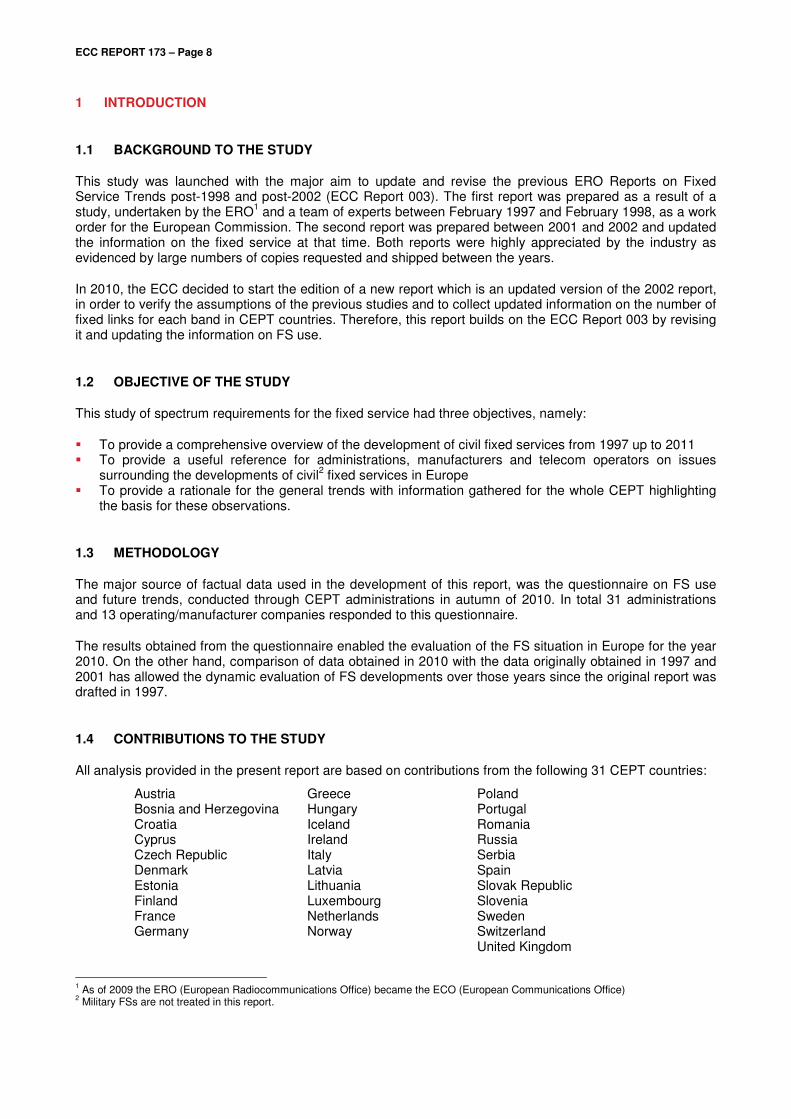
1 INTRODUCTION
1.1 BACKGROUND TO THE STUDY
This study was launched with the major aim to update and revise the previous ERO Reports on Fixed Service Trends post-1998 and post-2002 (ECC Report 003). The first report was prepared as a result of a study, undertaken by the ERO
1 and a team of experts between February 1997 and February 1998, as a work
order for the European Commission. The second report was prepared between 2001 and 2002 and updated the information on the fixed service at that time. Both reports were highly appreciated by the industry as evidenced by large numbers of copies requested and shipped between the years.
In 2010, the ECC decided to start the edition of a new report which is an updated version of the 2002 report, in order to verify the assumptions of the previous studies and to collect updated information on the number of fixed links for each band in CEPT countries. Therefore, this report builds on the ECC Report 003 by revising it and updating the information on FS use.
1.2 OBJECTIVE OF THE STUDY
This study of spectrum requirements for the fixed service had three objectives, namely:
� To provide a comprehensive overview of the development of civil fixed services from 1997 up to 2011 � To provide a useful reference for administrations, manufacturers and telecom operators on issues
surrounding the developments of civil2 fixed services in Europe
� To provide a rationale for the general trends with information gathered for the whole CEPT highlighting the basis for these observations.
1.3 METHODOLOGY
The major source of factual data used in the development of this report, was the questionnaire on FS use and future trends, conducted through CEPT administrations in autumn of 2010. In total 31 administrations and 13 operating/manufacturer companies responded to this questionnaire.
The results obtained from the questionnaire enabled the evaluation of the FS situation in Europe for the year 2010. On the other hand, comparison of data obtained in 2010 with the data originally obtained in 1997 and 2001 has allowed the dynamic evaluation of FS developments over those years since the original report was drafted in 1997.
1.4 CONTRIBUTIONS TO THE STUDY
All analysis provided in the present report are based on contributions from the following 31 CEPT countries:
Austria Bosnia and Herzegovina Croatia Cyprus Czech Republic Denmark Estonia Finland France Germany
Greece Hungary Iceland Ireland Italy Latvia Lithuania Luxembourg Netherlands Norway
Poland Portugal Romania Russia Serbia Spain Slovak Republic Slovenia Sweden Switzerland United Kingdom
1 As of 2009 the ERO (European Radiocommunications Office) became the ECO (European Communications Office)
2 Military FSs are not treated in this report.

ECC REPORT 173 – Page 9
Also 13 operating/manufacturer companies/associations provided their feedbacks:
4RF communications Aviat Networks Bluwan Cambridge Broadband Networks ETNO
Huawei NEC Nokia Siemens Network RaiWay
SIAE Microelettronica TelecomConsult SVK Telenor Norway AS TeliaSonera
Whenever a comparison with the previous reports was made, only the first 19 CEPT countries in Table 1, that replied to all three reports questionnaires, were considered.
Table 1: Countries replies to the questionnaires
Country
Code Country
1997 2001 2010 Country considered
in the comparison
AUT Austria X X X X
HRV Croatia X X X X
CZE Czech Republic X X X X
DNK Denmark X X X X
FIN Finland X X X X
F France X X X X
D Germany X X X X
HNG Hungary X X X X
IRL Ireland X X X X
I Italy X X X X
LVA Latvia X X X X
LTU Lithuania X X X X
LUX Luxembourg X X X X
NOR Norway X X X X
POR Portugal X X X X
SVN Slovenia X X X X
S Sweden X X X X
SUI Switzerland X X X X
G United Kingdom X X X X
BIH Bosnia and Herzegovina X
CYP Cyprus X
EST Estonia X X
GRC Greece X
ISL Iceland X X
HOL Netherlands X
POL Poland X
ROU Romania X
RUS Russian Federation X
SRB Serbia X
SVK Slovak Republic X X
E Spain X
BEL Belgium X X
BUL Bulgaria X

ECC REPORT 173 – Page 10
Country
Code Country
TUR Turkey
Total
The summary of the responses on national FS use in tabular form is given in Annex 1 to the report.
2 DEFINITIONS
Term Definition
CAGR The Compound annual growth rate
gain over a given time
where
V(t0) : start value
V(tn) : finish value
tn − t0 : number of years
Terabyte 1 thousand Gigabytes
Petabyte 1 thousand Terabytes
Exabyte 1 thousand Petabytes
3 EUROPEAN FS MARKET AND ITS REGULATION
3.1 GENERAL MARKET TREND
Liberalisation of telecommunications has been taking place and consolidating on a global basis over ten years with new operators entering increasingly competitive markets and offering an increatelecommunication services. Many operators are also forming strategic alliances in order to expand their markets beyond primarily national boundaries an
This new market environment has enabled real competition in telecommunications, which has had an impact not just on the provision of telecommunicationwireless or cable.
Aside from mobile communications, which are by now well and long established users of radio technologies, many other “traditional” telecom operators started to look more attentively to wireless communications to facilitate speedy implementation, flexibilitduring the 1990’s, has continued to happen and may be observed both in the provisioning of fixed wireless access for customer connections and in other areas like, for example, in supporting mobile networks or for other telecommunication networks. This new demand for using radio technologies comes in addition to a considerable fixed radio network infrastructures already for long time in use by incumbent operators, as part of their PSTN network, national broadcast distribution (feeder links to regional VHF/UHF transmitters) networks, etc.
The most significant increases of FS assignments over the area of infrastructure support for public mobile networks, where the reported number of links increased by more than 24.5%to increase further with the expected growth in capacity and number othe introduction of UMTS/HSPA/HSPA+/
1997 2001 2010
X X
23 23 31
The summary of the responses on national FS use in tabular form is given in Annex 1 to the report.
Compound annual growth rate is a specific term for the smoothed annualized
gain over a given time period. It is defined as:
: start value
: finish value
: number of years
1 thousand Gigabytes
1 thousand Terabytes
1 thousand Petabytes
ND ITS REGULATION
GENERAL MARKET TRENDS
Liberalisation of telecommunications has been taking place and consolidating on a global basis over years with new operators entering increasingly competitive markets and offering an increa
services. Many operators are also forming strategic alliances in order to expand their markets beyond primarily national boundaries and to enter new areas.
This new market environment has enabled real competition in telecommunications, which has had an impact provision of telecommunication services, but also on the supporting infrastructure, whether
Aside from mobile communications, which are by now well and long established users of radio technologies, many other “traditional” telecom operators started to look more attentively to wireless communications to facilitate speedy implementation, flexibility and economical provision of their networks. This trend, started
, has continued to happen and may be observed both in the provisioning of fixed wireless access for customer connections and in other areas like, for example, in supporting mobile networks or for other telecommunication networks. This new demand for using radio technologies comes in addition to a considerable fixed radio network infrastructures already for long time in use by
part of their PSTN network, national broadcast distribution (feeder links to regional VHF/UHF transmitters) networks, etc.
The most significant increases of FS assignments over the last two decades still came in particular from the upport for public mobile networks, where the reported number of
% per year in average between 1997 and 2010. This demand is expected to increase further with the expected growth in capacity and number of connected nodes (base stations) with
HSPA/HSPA+/LTE/IMT-Advanced. Provisioning of infrastructure support through
Country considered
in the comparison
19
The summary of the responses on national FS use in tabular form is given in Annex 1 to the report.
is a specific term for the smoothed annualized
Liberalisation of telecommunications has been taking place and consolidating on a global basis over the last years with new operators entering increasingly competitive markets and offering an increasing range of
services. Many operators are also forming strategic alliances in order to expand their
This new market environment has enabled real competition in telecommunications, which has had an impact services, but also on the supporting infrastructure, whether
Aside from mobile communications, which are by now well and long established users of radio technologies, many other “traditional” telecom operators started to look more attentively to wireless communications to
y and economical provision of their networks. This trend, started , has continued to happen and may be observed both in the provisioning of fixed wireless
access for customer connections and in other areas like, for example, in supporting infrastructure for public mobile networks or for other telecommunication networks. This new demand for using radio technologies comes in addition to a considerable fixed radio network infrastructures already for long time in use by
part of their PSTN network, national broadcast distribution (feeder links to regional
still came in particular from the upport for public mobile networks, where the reported number of Point to Point (P-P)
. This demand is expected f connected nodes (base stations) with
Advanced. Provisioning of infrastructure support through

ECC REPORT 173 – Page 11
various Point-to-MultiPoint (P-MP) technologies (e.g. universally licensed FWA networks and tailored P-MP backbone networks) is also being considered, or already implemented in some countries as a viable alternative option in the environment with high density of served base stations (e.g. dense urban areas).
The growth in number of FS links is likely to continue for the foreseeable future. In that respect it may be noted, that CEPT has already made several successful moves towards ensuring favourable conditions for such growth, by developing ERC and ECC Decisions, Recommendations with relevant channel arrangements and identifying additional bands for high density applications in the FS, including FWA and infrastructure support. The objective of new recommendations and the approach to management of the radio spectrum is to promote innovation and competition in the provision of wireless services. Radio spectrum is a key resource for communication services and its efficient utilisation is critical in the future.
3.2 ROLE OF FIXED SERVICE
Fixed radio links provide a transmission path between two or more fixed points for provision of telecommunication services, such as voice, data or video transmission. Typical user sectors for fixed links are telecom operators (mobile network infrastructure, fixed/mobile network backbone links – see Figure 1 as an example of the mobile infrastructure), corporate users (private data networks, connection of remote premises, etc. – see Figure 2) and private users (customer access to PSTN or other networks – see Figure 3). Within each application either P-P or P-MP can be used for each link.
Figure 1: Example of fixed links deployment within the infrastructure of mobile network
Figure 2: Example of a private radio relay link (e.g. for LAN, PABX inter-connection of premises)

ECC REPORT 173 – Page 12
Figure 3: Example of P-MP FWA network including a P-P infrastructure connection
Fixed radio links, instead of cable and fibre, are often the preferred solution where constraints such as cost, local topography (e.g., mountainous terrain or paths across water) and the need for access to remote rural regions are fundamental considerations. In many such cases fixed radio links are the only practical solution.
Also in today’s competitive environment the ability to further roll out a network rapidly by using radio as transmission media provides an operator with the flexibility to install and scale transmission paths as and when required. This is particularly important as it allows the possibility to reduce and better distribute the required investments, by testing the service and directing revenues as they appear into further development of a network where most use occurs.
It is appropriate to note that being the integral and indispensable part of overall telecommunication infrastructure, fixed service provides a significant contribution to national economies in financial terms.
Furthermore public mobile service is currently one of the most significant users of spectrum in Europe and all forecasts estimate that it will also be the source of the highest demand for spectrum over the next 10 years. This is primarily due to the expected growth in data traffic over the coming years. Figure 4 presents an Alcatel-Lucent forecast of global mobile yearly traffic up to the year 2015 where several Exabytes are foreseen (1 Exabyte = 1 million Terabytes).
Sectorised deployment
Deployment with omni -directional antenna
Sectorised deployment

ECC REPORT 173 – Page 13
Figure 4: Global mobile yearly data traffic forecast for year 2015 (source Alcatel-Lucent)
Similar projections are also coming from other companies: Cisco (Cisco VNI 2011) estimates that data traffic in Europe will grow at a Compound Annual Growth Rate (CAGR) of 91% in 2010-15 as indicated in Figure 5.
Figure 5: Mobile data traffic forecast for Western Europe (source Cisco)
As a further example, in France 80% of fixed service link capacity is used by mobile operators. In the near future it is expected an important growth of data traffic due to broadband backhaul links supporting terrestrial cellular networks. For instance the increased smartphone usage with several new applications running is likely to increase network congestion. The growth trend for some of such devices over the last two years is presented in Figure 6.
0
10
20
30
40
50
60
70
80
2010 2011 2012 2013 2014 2015
Year
Glo
bal ExaB
yte
per Year
Widescreen Devices
Smartphone
Feature Phone

ECC REPORT 173 – Page 14
Figure 6: Total global number of smartphones sold (source: Plum Consulting, Apple quarterly financial results, Gartner)
3.3 FIXED SERVICE GROWTH
The FS usage figures obtained from the questionnaire of 2011, compared with the usage figures obtained in previous studies in 1997 and 2001 (see Figure 7), show an overall increase of number of reported FS links in Europe by 75% between 2001-2010, compared to 33% between 1997 – 2001. This corresponds to a CAGR of 6.4% between 2001-2010, compared to 7.3% between 1997 – 2001.

Figure 7: Number of reported FS links in Europe for the 19 countries that replied to all three
The major growth in FS usage was reported in the area of infrastructure support (151846 in 2001 and 73542 in 1997). This trend shounetworks. These networks have developed rapidly over the last few years and the arrival of UMTS/HSPA/HSPA+/LTE/IMT-Advanced, with the broadband mobile access networks, will imply further increase in FS use for such purpose.
3.4 REGULATORY REGIME FOR
In addition to data on actual use and future trends of FS in their countries, CEPT administrations were asked to describe the principles used in managing assignments of FS links.appears that all CEPT administrations as a general rule apply centralAdministration is the responsible manager of the FS frequency assignments. not changed for the last two decades. the bands exclusively used by a particular authority or Ministry are subject only to notification procedure (for details see Annex 2).
However, within the framework of centralised manageadministrations do carry out block allocation of frequencies in selected bands, i.e. where licensees are allocated a block of spectrum within which they
Number of reported FS links in Europe for the 19 countries that replied to all three questionnaires
was reported in the area of infrastructure support (3in 1997). This trend should be attributable to the major success of the 3G mobile
networks. These networks have developed rapidly over the last few years and the arrival of Advanced, with the broadband mobile access networks, will imply further
FS use for such purpose.
EGULATORY REGIME FOR FS
data on actual use and future trends of FS in their countries, CEPT administrations were asked to describe the principles used in managing assignments of FS links. From the reappears that all CEPT administrations as a general rule apply central management, i.e. where the Administration is the responsible manager of the FS frequency assignments. This central management has not changed for the last two decades. The exceptions are few, such as in France, were FS operations within the bands exclusively used by a particular authority or Ministry are subject only to notification procedure (for
However, within the framework of centralised management of frequency assignment for the FS, many administrations do carry out block allocation of frequencies in selected bands, i.e. where licensees are
within which they deploy and manage links themselves.
ECC REPORT 173 – Page 15
Number of reported FS links in Europe for the 19 countries that replied to all three
308285 links in 2010 vs. ld be attributable to the major success of the 3G mobile
networks. These networks have developed rapidly over the last few years and the arrival of Advanced, with the broadband mobile access networks, will imply further
data on actual use and future trends of FS in their countries, CEPT administrations were asked From the responses received it
management, i.e. where the This central management has
The exceptions are few, such as in France, were FS operations within the bands exclusively used by a particular authority or Ministry are subject only to notification procedure (for
ment of frequency assignment for the FS, many administrations do carry out block allocation of frequencies in selected bands, i.e. where licensees are
links themselves.

ECC REPORT 173 – Page 16
3.5 FS ASSIGNMENT METHODS
The assignment methods currently present in the Fixed Service regulatory framework of most CEPT countries may be summarised in the following four categories:
1. Individual licensing: this is the conventional link-by-link coordination, usually made under administration’s responsibility; sometime, the administration delegates this task to the operators, but it keep control of the national and cross-border interference situation. This is currently assumed to be the most efficient method of spectrum usage for P-P links networks.
2. Light licensing: even if the terminology itself is not completely agreed among CEPT administrations (see ECC Report 132), the common understanding, when fixed P-P links are concerned, refers to a link-by-link coordination, under users responsibility, reflected in the definition given by ECC Report 80 as: “A ‘light licensing regime” is a combination of licence-exempt use and protection of users of spectrum. This model has a “first come first served” feature where the user notifies the regulator with the position and characteristics of the stations. The database of installed stations containing appropriate technical parameters (location, frequency, power, antenna etc.) is publicly available and should thus be consulted before installing new stations. If the transmitter can be installed without affecting stations already registered (i.e. not exceeding a pre-defined interference criteria), the new station can be recorded in the database. A mechanism remains necessary to enable a new entrant to challenge whether a station already recorded is really used or not. New entrants should be able to find an agreement with existing users in case interference criteria are exceeded.” From the spectrum usage point of view, this method is, in principle, equivalent to the individual licensing; only the potential risks of “errors” or “misuses” in the coordination process might be higher because of the number of actors involved, some of them also not enough technically prepared.
3. Block assignment: the assignment might be made through licensing (renewable, but not permanent) or through public auction (permanent). This is most common when FWA (P-MP) is concerned and the user is usually free to use the block at best to deploy its network; in some cases, there might even be no limitation to the wireless communications methods used in the block (e.g. P-P and/or P-MP, terrestrial and/or satellite or any other innovative technology or architecture). In the most popular bands for this method, ECC recommendations exist suggesting intra-blocks protections guidelines in terms of guard bands or block-edge masks (BEM). For some frequency bands this method is considered the best compromise between efficient spectrum usage and flexibility for the user.
4. License exempt: this method offers the most flexible and cheap usage, but does not guarantee any interference protection. It is most popular in specific bands (e.g. 2.4 and 5 GHz) where SRD are allocated, but FS applications may also be accommodated; in addition, it is often used in bands between 57 GHz and 64 GHz less attractive due to the unfavourable propagation attenuation.
From the responses to the questionnaire individual licensing (frequency assignment of each individual link assignment method) continues to be the predominant method in making assignments in the majority of bands for which information has been provided. This is followed by block allocation which while does not dominate as a method tends to be applied across most bands. Block allocation is on par with link by link assignment in the 3.4 – 4.2 GHz range and 24.5 – 26.5 GHz bands. Reasons for this is presumed to be related to the initial P-P links deployment, later on partially switched to possible P-MP applications.
Licence exemption becomes more prominent in bands between 57 GHz and 64 GHz, where oxygen absorption is significant, reducing the risk of interference. Above 64 GHz (i.e. in 64 – 66 GHz and in recently CEPT opened 71 – 76/81 – 86 GHz and 92 – 95 GHz bands) the favourable propagation conditions justify the fact that in most responses the link-by-link assignment predominates over the use of licence exemption. However, in some administrations there is also the emergence of a self-coordinated approach, in conjunction of light licensing, to making assignments in these bands.
The decision of an Administration for a particular assignment procedure for a particular band or an application can be influenced by a number of factors, which could have different backgrounds such as regulatory, administrative, technology/application or market driven:
� National Regulatory Framework: An Administration is bound in its regulatory framework provided by their Telecommunications Act, which gives administrations certain possibilities, or flexibility limits in terms of the frequency assignment. On the other hand, this legal framework could also restrict to certain procedures, which may not always be beneficial under specific circumstances.

ECC REPORT 173 – Page 17
� Administrative Factors: The choice for an assignment procedure is also very much influenced by administrative factors. The ability to handle the incoming amount of frequency assignment applications largely depends on the efficiency of the administrative handling, the assignment tool used and the manpower available in a particular Administration.
Propagation factors: The current interest for very high capacity systems in frequency bands higher than 55 GHz, implies that the additional oxygen absorption has to be taken into account. The region between 57 GHz to 64 GHz might be more appropriate for unlicensed (uncoordinated) deployment, while above this range a coordinated (either licensed or light licensed option) deployments might offer a better spectrum usage.
� Technology Drivers: As already reported in the ECC Report 003 in 2002, the decision for or against the individual assignment or block assignment also depends on the technology, employed by a particular application in question. For example, in the case of P-MP systems, an individual assignment of each single link could produce an unnecessary administrative burden for the operator and the Administration. In this case, the individual frequency assignment for the base station or at least information on the base station location could be sufficient for the Administration to impose measures to ensure co-existence with neighbouring assignments of the same or different systems (operators).
� Market Forces: Market forces also influence the decision for the assignment method. The time pressure for the introduction of new systems could impose the use of a speedy process for the frequency assignment in order not to hinder the rollout of networks, which are intended to enter the market quickly. Also the expected/desired major utilisation (e.g. for private or public infrastructures) may have a role in selecting the assignment method.
3.6 FREQUENCY BANDS REFARMING
Refarming is a set of administrative, economic and technical measures, aimed at achieving the recovery of a particular frequency band from its existing users for the purpose of re-assignment, either for new uses, or for the introduction of new spectrally efficient technologies. For the FS sector, it means to vacate some of the occupied bands and obtaining new bands for development of new services. The most notable examples of FS surrendering a particular band, are the bands around 2 GHz, which were historically used for FS communications, but which had to be re-located to mobile services since the early 1990’s. In counterparty, FS gained wider access to higher bands, better suited for fixed links.
It is an important tool to optimize spectrum efficiency with a better re-arrangement of FS bands, used for different users or services. Examples of such “internal” refarming may be the conversion from P-P to P-MP use (e.g. in the band 3400-3600 MHz), the conversion from military to civil FS use, etc. Therefore FS spectrum management authorities should be well aware of advantages and mechanisms of spectrum refarming as well as of the re-deployment costs (e.g. to relocate current users in new bands or in new channel plan). For this reason, in practice, it has to be kept in mind that in some cases refarming process may be extremely difficult, especially when the concerned band has reached a high level of FS deployment (e.g. the 7/8 GHz bands where many countries might not be in a position to refarm the bands, due to the deployment level already reached).
3.7 SPECTRUM TRADING
Spectrum trading enables the holders of certain wireless licenses to transfer (or, since May 2011, also to lease) their rights to use radio spectrum to another party in accordance with the conditions attached to their authorisations and in accordance with national procedures. This is expressly provided for by the EU framework for electronic communications networks and services. The framework also empowers the EU Commission to adopt appropriate implementing measures to identify frequency bands in which trading must be allowed although this does not extend to frequencies used for broadcasting. This is related to EU countries only and, as of the date of this report the EU Commission has not adopted any such measures yet.
Nevertheless national procedures to allow trading of spectrum have been implemented for fixed service spectrum in some CEPT countries.

ECC REPORT 173 – Page 18
4 TECHNOLOGY TRENDS
4.1 P-P LINKS
The technology evolution is obviously continuously driven by the market demand, which implies continuous improvements in the payload management, error performance and spectral efficiency.
4.1.1 Payload management
The major market of P-P links is the mobile networks backhauling. This first of all indicates that higher and higher capacity systems will be mostly required.
A second major change in the market demand is the progressive evolution of the radio traffic nature from TDM (e.g. PDH and SDH mostly used in current mobile networks) to Packet traffic (e.g. IP/Ethernet required by the new generation of mobile networks).
Such passage will be smooth (i.e. mixed old and new network areas need to coexist and interact for long time) using initially Hybrid MW, which encapsulates native TDM and Packet services into the same radio frame (Figure 8a). Newest equipment can already be designed as full Packet radio system, which directly manage native packet traffic, while, using techniques like Pseudo-Wire (PW) and Circuit Emulation (CES) are able to merge TDM traffic into Packet traffic on the same common transport frame (Figure 8b).
Proper mechanisms will have to be established to guarantee to each transported traffic type, e.g. voice, real-time and data, the right performances, as error ratio and jitter, shall be employed. Packet QoS will be used as flow control technique in particular when Adaptive Modulation (AM) is enabled in order to schedule traffic quote to be added or dropped.
Figure 8: Evolution from Hybrid MW (a) towards Packet MW (b)
a)
b)
TDM
PROCESSING
ETHERNET
PROCESSING
ADM (Add and Drop Multiplexer)
Ethernet Switch
RA
DIO
FR
AM
ER
Ethernet
TDM
ODU
TDM to ETH
PROCESSING
ET
HE
RN
ET
PR
OC
ES
SIN
G
Ethernet Switch
RA
DIO
FR
AM
ER
Ethernet
TDM
ODU

ECC REPORT 173 – Page 19
4.1.2 Modulation, spectral efficiency and error performance enhancement
Modulation and spectral efficiency
Advances in the area of modulation and coding (error correction) technology, new modem chips, and MW components like low phase noise VCO, are having a profound effect on the increase of capacities of P-P links. Today modulation schemes of as high as 128-QAM are used widely for trunk/infrastructure networks and modulation as high as 16-QAM is increasingly used for access links. New equipment can cope with modulation formats up to 512-QAM and the introduction in the market of 1024-QAM systems is expected in short time as shown in Figure 9.
The flexibility in applying higher modulation orders to achieve higher throughput in a given channel bandwidth may allow operators to solve capacity problems within the conditions of spectrum scarcity in a particular frequency band .
The actual increase in transport capacity with the modulation format follows a growing trend only with the logarithm of the modulation index. Therefore the increase becomes, in percentage, lower and lower with the modulation index increase. Taking also into account the need for more redundant error correction codes, a further enhancement beyond 1024-QAM might no longer justify the technology investment for their development.
Figure 9: Spectral Efficiency versus Modulation Level (example for CS=28 MHz and symbol frequency of around 0.9CS)
Polarization
The additional use of Cross-Polarization Interference Cancellation (XPIC) to double capacity in Co-Channel Dual-Polarization (CCDP) applications is already a well consolidated technique and should also be more and more utilised.
Channel size and new bands
A further possibility for increasing link capacity is the use of systems operating on wider CS. The following opportunities are likely to be more and more used:
4QAM/4PSK
16QAM
32QAM
64QAM
128QAM
256QAM
512QAM
1024QAM
1
2
3
4
5
6
7
8
9
10
0 100 200 300 400 500 600 700 800 900 1000 1100
Sp
ect
ral E
ffic
ien
cy (
Mb
it/s
/MH
z)
Modulation Index (M-QAM)

ECC REPORT 173 – Page 20
• bands below about 13 GHz: 2x28, 2x29.65 and 2x40 MHz CS; options recently introduced in relevant ECC and ITU-R recommended channel arrangements, which could be used whenever the coordination with existing networks permits.
• bands in range 15-57 GHz: 56 and, up to 42 GHz, 112MHz CS3;
• bands above 57 GHz: e.g. Nx250 MHz CS in 71-76/81-86 GHz. Extreme High Frequency Band (E-Band), 71-76/81-86 GHz and, with minor impact, the forthcoming 92-95 GHz band result particular promising in term of capacity (multi Gbit/s radio). Equipment in these bands are currently challenging in terms of VCO phase noise, component analogue bandwidth and processing / sampling frequency.
On the market E-Band equipment with simple modulation formats (maximum 4-QAM) are already present but industries are working and very confident on the availability of more complex equipment with higher modulation formats which could form very high density networks provided that a suitable co-ordinated frequency regime is adopted.
The technology development expected for the E-band might also relive the interest for other high frequency bands, such as the 50, the 52 and the 55 GHz, which are presently poorly used even if ECC Recommendations are already available since many years.
Adaptive modulation
The new services offered to the end-user, over IP based platforms, are going to evolve with different degrees of quality (pay for quality) from the simplest “best effort” to different increasing degrees of guaranteed traffic availabilities. Therefore, the AM algorithm perfectly fits the quality requirement and allows the use of high modulation schemes even in access links. AM is used to dynamically increase radio throughput by scaling modulation schemes (e.g. 4-QAM → 64-QAM → 256-QAM) according to the current propagation condition (Figure 10).
The modulation scheme can be changed errorless and traffic is added during modulation scaling up or dropped during modulation scaling down according to the assigned priority profile.
Conversely, for high capacity links in core networks, AM can be used to further increase link availability, for the high priority fraction of the payload, by means of scaling down to lower modulation formats (e.g. 256-QAM → 64-QAM → 4-QAM) during fading condition.
It should be noted that in bands above 60 GHz, where very large bandwidth are possible, in the order of 1 GHz or more, the technology might not allow the use of very high modulation formats. Present equipment offer no more than 2 or 4 states modulation formats and 16/32 QAM will already be a challenge for the future. For this reason a different adaptive methodology, referred in ETSI EN 302 217-3 as “band-adaptive systems”, might also be employed. During adverse propagation, the system extends the receiver BER threshold, for a portion of the payload, reducing the bandwidth rather than dropping the modulation level. In this way longer links may also be covered with satisfactory capacity/quality trade off.
3 In this frequency range the band 40.5 – 42.5 GHz has been opened to P-P systems too.

ECC REPORT 173 – Page 21
256-QAM 64-QAM4-QAM
4-PSK64-QAM 256-QAM
Time
Ca
pa
city
(%
)
99.999%
(Outage: 5.25min/y)
99.99%
(Outage: 52.562min/y)
99.9%
(Outage: 8.76h/y)
100
75
25
Av
ail
ab
ilit
y
Figure 10: Adaptive Modulation example (availability/outage figures are indicative)
Link design methodology
The potential higher susceptibility to interference is successfully overcome by applying careful planning of link budgets and, when the coordination procedure foresee the use of Automatic Transmit Power Control (ATPC) to limit transmitted power in congested networks, considering the joint interaction of ATPC and Adaptive Modulation (AM).The joint use of AM and ATPC requires careful consideration in order to balance the advantages separately offered by those technologies.
AM Error free
switching margin
RSL
variations
reference mode (16 QAM) threshold
Min safe “clear sky” RSL
necessary for full AM
functionality
16QAM (Reference Mode)
<10-12
Err. free
256QAM
<10-12
10-6
Err. free
64QAM
<10-12
<10-12
4QAM/
4PSK
Err. free
10-6
Err. free
Possible
FM Reduction on
full capacity
Thr BER
Minimum FM
for fully exploiting the
AM functionality
Possible modulation lower than reference enabled for
higher availability in critical payload
Figure 11: Fade Margin impact to Adaptive Modulation

ECC REPORT 173 – Page 22
Figure 11 shows the problematic related to the use of adaptive modulation, independently from the ATPC use; as indicative reference, only four examples of modulation formats are shown but any format could apply depending on the implementation. Figure 11 shows that, as a function of the reference modulation format and the AM maximum available modulation format, a minimum nominal “clear sky” RSL (corresponding to a minimum fade margin) should be provided for fully exploiting the AM potentiality. For defining this minimum RSL a number of safeguards for implementation tolerance for Received Signal Level (RSL) detection and TX power setting tolerances should be taken into account. Consequently, very short hops might need special attention (see section 5.1.3 where short hops need is further detailed).
When ATPC is added in the coordination process of AM links, Figure 12 shows that the available ATPC range is link-by-link variable and, in addition, the available ATPC range is limited by the above described safeguards for guaranteeing error free operation, to which an additional ATPC activation safeguard should be added; this may limit the range of ATPC available for planning purpose. The minimum RSL defined for planning the network with ATPC enabled (nominal clear sky RSL with ATPC enabled) should be higher than the minimum required by all those systems safeguards for avoiding malfunctions or preventing full use of the AM operation.
It should also be noted that, in AM systems, a portion of available ATPC range is always enabled; this, here called “step ATPC”, is used for managing the required output power drop for linearity purpose between the “reference modulation” (i.e. 16 QAM in the example) and the highest modulation (i.e. 256 QAM in the example). The “total ATPC” available for planning purpose is then achieved by adding the conventional presettable “linear ATPC” range (see Figure 12) according the formula:
AATPC total = AATPC step.+ AATPC linear
These effects have to be taken into account for a case-by-case trade-off between the link parameters. In hops where the required Fade Margin (FM) is low, it might be possible that there is no margin either for permitting the excursion of the whole set of modulation formats and/or for permitting any ATPC range.
RSL
variations
Nominal RSL for Clear sky (ATPC disabled) for FM calculation of the ref. 16QAM (actual hop)
FM
of
the
act
ua
l (1
6 Q
AM
)
ho
p u
nd
er
con
sid
era
tio
n
Additional ATPC
tolerance safeguard
Ma
xim
um
av
ail
ab
le F
M f
or
refe
ren
ce
form
at
(16
QA
M l
on
ge
st h
op
)
Nominal RSL for Clear sky (ATPC disabled) for FM calculation of the ref. 16QAM (longest hop)
reference mode (16 QAM) threshold
AATPC max, total
AATPC actual hop, total
Nominal RSL for Clear sky defined for
ATPC coordination of the network
16QAM (Reference Mode)
<10-12
Err
. fr
ee
256QAM
<10-12
10-6
Err.
free
64QAM
<10-12
<10-12
4QAM/
4PSK
Err
. fr
ee
10-6
Err
. fr
ee
Thr BER
ATPC safer min nominal RSL for
full AM functionality
Min safe “clear sky” RSL necessary
for full AM functionality
Nominal RSL for Clear sky (ATPC disabled) at 256QAM operation (actual hop)
Nominal RSL for Clear sky (ATPC disabled) at 256QAM operation (longest hop)
“Ste
p”
AT
PC
fro
m 1
6Q
AM
to
25
6 Q
AM
ou
tpu
t p
ow
er
Figure 12: Fade Margin and ATPC range impact to Adaptive Modulation

ECC REPORT 173 – Page 23
4.1.3 Backhaul network evolution and its challenges
With the progressive introduction of more and more broadband services offered by new generation of LTE mobile systems, also their backhaul networks need to suitably respond to the change.
The expected growth of needed capacity implies also that, at least in highly populated urban areas, the base stations will use smaller size cell footprint and thus their density will increase. Consequently, FS backhauling link hop should be significantly reduced.
In addition equipment may be installed on light poles at street level and shall not have a large visual impact. This will drive the use of smaller/integral and/or adaptive antennas (see section 4.3).
An overall trend for smaller size cells is also expected in any geographical area; therefore, the upgrading or new deployment of mobile backhauling networks will, in general, require significantly shorter hops, either on the lower layer (connections between base stations using higher frequency bands e.g. 23 GHz to 42 GHz) and on the higher layer (between larger and more distant exchange stations using lower frequency bands e.g. 15 GHz down to 6 GHz).
Correspondent evolution in the coordination
The above expected network evolutions pose additional challenges to the network engineering on both operator and regulator sides due to the significantly lower fade margin needed for the required availability.
The following coordination elements have to be considered:
� The fade margin, usually calculated for the availability objective at BER ≅ 10-6
, would result only in a few decibels.
o It could likely become lower than the safeguard clear sky margin for guaranteeing the Residual BER (RBER) objective, conservatively set in present ETSI standards
4 to be 10 dB
o Conventional frequency planning procedure usually fix the maximum transmit EIRP for matching the fade margin needed for “availability objective” (Recommendation ITU-R F.1703)
5. In such short hops, this obviously means that, for fulfilling also the other “error
performance objectives” (Recommendation ITU-R F.1668), an “extra EIRP margin” should be assigned in the coordination process.
� Use of adaptive modulation systems for increasing data capacity in clear sky conditions (desired by the operators for obvious economic reasons) and of ATPC for improving the spectrum usage (often considered in the licensing/coordination process).
o This even more increases the difference between the minimum fade margin for implementing these techniques (see Figure 11), and the actual calculated for “availability” only.
o This would imply an even higher “extra EIRP margin” to be possibly assigned in the coordination process (unless all these hops are designed considering only the topmost modulation format).
o The “extra EIRP margin” would imply an higher interference situation; however, it might be tolerable due to larger fade margin if the coordination process includes a C/I impact larger than usual.
� The very low fade margin, in addition to the continuously more demanding low visual impact, implies the use of low antenna gain (small size).
o Low gain antennas physically imply a lower directivity (ETSI classes 3 and 4 could not be possible).
o Low directivity antennas imply a reduced nodal frequency reuse rate. o The apparent drawbacks of small antennas should be considered in the light of other
possible characteristics of the new network scenario (higher links density, “extra margin”, larger C/I tolerance, …).
In conclusion, it is expected that further studies would be needed in the field of frequency coordination for very dense networks, where the conventional methods might no longer be appropriate.
4 See EN 302 217-2-1
5 It is usually assumed that other ITU-R “error performance objectives” are automatically met.

ECC REPORT 173 – Page 24
Figure 13: Urban area backhauling example
Further evolutionary scenario
Three other technological topics are under assessment for possible applications in the FS marketplace:
� Non Line of Sight (NLOS) or Quasi Line of Sight (QLOS) backhauling applications in low frequency bands (typically below, but not limited to, 6 GHz
6); which may solve the interconnection of mobile pico-
cells at street levels. An important part of the challenge is the search for suitable frequency band(s) for such applications; it is well known that frequency resources below 6 GHz are very scarce and most of the “fixed allocations” have already been switched to, or looked for, MWA/BWA use, which imply, in common practice, that the bands are usually auctioned in blocks of relatively small size. This has already generated the idea of “in-band backhauling” (i.e. the use of the same auctioned block for both access and backhauling); however, this sometimes conflicts with the national licensing/auctioning rules (e.g. requiring “access only”) or, in any case, imply that the backhaul capacity would reduce the access capability and that, standing the limited block bandwidth, there will be strong limitation to the planning of P-P links (in term of capacity and availability of channels for interference reduction purpose). A second option could be the “off-band backhauling” (i.e. the use of a frequency band different from that of the access); possibly, the few bands still in use for conventional coordinated P-P deployment (e.g. 1.5 GHz, 2 GHz and 4 GHz), but not presently expected to support new systems deployment (see band-by-band analysis in Annex 1), might be taken into consideration. A third option of using license exempt bands (e.g. 2.4 GHz and 5 GHz), provided that EIRP limitation currently enforced would permit practical P-P application could be limited by the already extensive use for “urban” applications (RLAN) and highly impacting technical limitations (DFS for primary radars protection); nevertheless, it still deserves careful analysis.
� Multiple-Input and Multiple-Output (MIMO) systems; which can increase capacity (Spatial Multiplexing) and/or link availability (Space Coding).
6 Recommendation ITU-R P.1411-5 “Propagation data and prediction methods for the planning of short-range outdoor
radiocommunication systems and radio local area networks in the frequency range 300 MHz to 100 GHz” contains NLoS propagation model in urban street canyons up to 16 GHz.

ECC REPORT 173 – Page 25
� Introduction of more complex “Cognitive radio system (CRS)” capability7.
4.2 P-MP AND MP-MP NETWORKS
4.2.1 Overview
P-MP networks are usually deployed in a dense manner employing the star configuration for their networking topology. It is necessary to ensure the transmission of high data rates between the base and terminal stations, and, at the same time, minimise the possible intra-system interference between different cells/sectors of the network. Due to the fact that link budgets for P-MP networks, by nature of their design, will be different for differing terminal stations, the appropriate modulation scheme to be employed in a scenario of different terminal stations should be carefully studied. An example of adaptive modulation in P-MP context is given in Figure 14.
CS32QAM
16QAM
4QAM/4PSK
Figure 14: Example of using adaptive modulation in a P-MP network, serving terminals with different link budgets
Multipoint-to-multipoint networks (MP-MP), also known as meshed networks, are intended to serve a large number of densely located fixed terminal stations. Meshed networks would therefore provide an alternative for P-MP networks. Meshed networks do not require central (base) stations for communications between terminal stations. Instead, each and every terminal station may act as a repeater and pass on the traffic to/from the next terminal station. Such networks would have only one or few drop nodes, which would provide interconnection of the meshed access network to the core transport network. Usually, all the nodes of the meshed network are located on the customer’s premises and act as both customer access and network repeater. In such a way traffic is routed to the addressed customer via one or many repeaters. Nodes located at the edge of the network initially act as terminating points, however may be later converted into repeaters with the further growth of the network, see Figure 15.
7 According ECC Report 159 and Report ITU-R SM.2152, a Cognitive Radio System (CRS) is: “A radio system employing technology
that allows the system to obtain knowledge of its operational and geographical environment, established policies and its internal state; to dynamically and autonomously adjust its operational parameters and protocols according to its obtained knowledge in order to achieve predefined objectives; and to learn from the results obtained.”

ECC REPORT 173 – Page 26
Figure 15: Topology example in a mesh network
Previously, minimal investment has been made in the P-MP and Multipoint-to-Multipoint (MP-MP) networks, owing to the lack of interest and difficult network planning prior to the adoption of block allocation in dedicated bands, the only evolution that was seen was related to the convergence with mobile applications in lower frequency bands. However P-MP has recently gained interest with the new generation of P-MP equipment available on the market. P-MP may be a useful element in the architecture, including mobile backhauling, for carrying packet data traffic in networks.
P-MP networks are finding application for providing last mile connections for mobile broadband networks. P-MP is suited to carrying the data traffic that is becoming the predominant type of information carried over mobile networks. When cellular mobile networks first appeared in the 80’s, they carried voice traffic. Later text messaging and then mobile data were introduced. Mobile data is quickly overtaking voice as the dominant form of traffic on mobile networks.
P-MP equipment is based on the observation that mobile data has one characteristic that makes it particularly challenging for FS link networks. Because packet data volume is based on the nature of the data usage characteristics of the users on the network, the traffic presented to the link has a distinct ‘shape’ – transient, unsynchronised peaks when users or applications are consuming data and troughs when users are idle. Such peaks and troughs are no longer correlated with a specific ‘busy hour’ that is common across the whole network (although an overall diurnal ‘swell’ may still be observed). The unpredictable nature of this data traffic makes it difficult for operators to design their network backhaul connections.
P-MP networks can address this challenge by statistically multiplexing the traffic from multiple sites to improve the efficiency of the network (see Figure 16). That allows the traffic to be merged so that the peaks from one mast ‘cancel out’ the troughs of another which improves system efficiency.

ECC REPORT 173 – Page 27
Figure 16: Example of statistical multiplexing gain
4.2.2 FWA Networks technology trend
Until around year 2000, when the forecast for development of FWA networks were much more encouraging, in particular in millimetric frequency bands, the "technology fight" between P-MP and MP-MP technologies, both claimed to be the best choice, was very strong. However, while first generation of P-MP networks were already in place and tested and commercially available, the proponents of MP-MP structures had soon disappeared due to the investment cuts in the field of “pure” FWA, in particular for the millimetric bands where most of the MP-MP studies aimed to; the market had, de facto, no opportunity of real testing MP-MP systems and networks.
Therefore, no new development is expected in the MP-MP field.
On the contrary, P-MP systems have been deployed and new generation of equipment are on the market. New products in higher frequencies have been developed and released in most of the popular P-MP bands including 10 GHz, 26, 28 GHz and 42 GHz.
In addition, in the lower frequency band, P-MP gained more momentum from the advent of BWA requirements on the market, where FWA and MWA are converging. Next section describes in detail the current situation in the field of BWA.
4.2.3 BWA Networks
With increased regulatory liberalisation and particularly in some lower frequency bands (currently 3400-3600 MHz and 3600-3800 MHz), FWA designations have been replaced with BWA designations and in many CEPT countries the original FWA spectrum authorisations have themselves been liberalised to reflect this new flexibility without any change of authorisation ownership. This new BWA designation introduces regulatory flexibility to support fixed, nomadic and mobile services and in many cases the access technology is derived both from fixed and/or mobile standardisation origins for building up Mobile/Fixed Communication Networks (MFCN). Definitions of BWA, FWA, NWA and MWA can be found in Recommendation ITU-R F.1399.
Standardisation activities for broadband FWA included the development of the IEEE 802.16 WirelessMAN-SCPHY specification covering the 10-66 GHz frequency range. This was mirrored within ETSI with the development of the HiperACCESS Technical Specification. The IEEE 802.16 standard was first amended to include the Fixed WirelessMAN OFDM PHY specification covering the licensed spectrum bands below 11 GHz. This was mirrored within ETSI with the development of the HiperMAN Technical Specification. Subsequent amendments to the IEEE 802.16 standard have introduced the WirelessMAN OFDMA PHY for

ECC REPORT 173 – Page 28
licensed spectrum bands below 11GHz with increasing support for mobile operation within the liberalised BWA spectrum designations. Further enhancements of the WirelessMAN OFDMA PHY have resulted in its adoption into the IMT technology family.
The WiMAX Forum industry body supported a standardised implementation of the IEEE 802.16 specification and has developed an accredited equipment certification process to ensure multi-vendor interoperability. WiMAX Certified products are available based on the WirelessMAN OFDM PHY specification targeting the 3400-3600 MHz band.
Frequency bands below 10 GHz
In lower frequency bands mobile applications are dominant so spectrum availability is limited for BWA/FWA. The 3400-3600MHz and 3600-3800 MHz ranges are the most popular for BWA and underpinned by harmonisation measures in ECC/DEC(07)02 and EC Decision 2008/411/EC.
However, following the identification of the frequency range 3400-3600 MHz for IMT systems at WRC-07, the mobile usage in this frequency range is likely to grow in coming years: the ECC has produced a new ECC Decision (ECC/DEC/(11)06) harmonising the band arrangements for MFCN usage (including IMT) in these bands. This complements the BWA framework with specific harmonised frequency channel arrangements. It should be noted that ECC/DEC/(11)06 provides, in 3400-3600 MHz, arrangements for both FDD and TDD systems, while, in 3600-3800 MHz, only TDD arrangements are considered; this should be taken into account also when simple FWA networks (including, when appropriate, backhauling infrastructure) are considered.
In the lightly licensed 5.8 GHz frequency band FWA (fixed and nomadic) operation continues to be possible on a national basis under the framework set by ECC Recommendation ECC/REC(06)04 and ETSI Harmonised Standard EN302 502. Coexistence considerations result in a low EIRP constraints and a need to implement a demanding Dynamic Frequency Selection (DFS) feature for the protection of primary Radiodetermination service.
Frequency bands above 10 GHz
In these frequency bands, 10.5, 26, 28 and 32 GHz despite early FWA standardisation efforts in ETSI and IEEE, technology costs remained high and commercial uncertainty prevented widespread take up and deployment for access applications.
In addition, the 42GHz frequency band, originally designated for exclusive Multimedia Wireless Systems (MWS) use (ECC/DEC(99)15) in 2009, was not exploited anywhere in Europe, apart from some applications in the Russian Federation. Thus during 2010 the ECC decided to open this frequency band also to P-P links in order to relieve link congestion in 38 GHz band which is heavily used for mobile backhauling.
However the recent explosion in data demand over mobile networks and the very rapid evolution of mobile technologies could lead to future renewed interest in the capacity of the higher frequency bands particularly in the light of technological developments that could lead to effective commercialization of new infrastructures in multipoint technology in these frequencies.
4.3 ANTENNAS FOR FS
4.3.1 Antenna types
Directive P-P antennas
At frequency bands of 60 GHz and higher, the smaller antenna size gives rise to the option of integral antennas. Integral antennas have several advantages, particularly in terms of equipment cost and cost of installation. Improved aesthetics granted by the simpler overall system design are also important if these systems are to be deployed as street furniture, which greater concern being shown by residents about the unsightly appearance of traditional radio tower and dish antennas.

ECC REPORT 173 – Page 29
P-P fixed service links use dish antennas to direct radiation between sites in order to achieve longer hop lengths and for reducing interference from and to other stations. Additionally, the microwave frequencies allow making highly efficient use of directive antennas, by reusing the same frequency channel several times at the same site into different directions. Reuse depends on many parameters, e.g. the antenna radiation pattern and the required interference attenuation.
Antenna reference radiation patterns for P-P are available from antenna manufacturers or they can be estimated, for sharing studies, for bands below 30 MHz from the Recommendation ITU-R F.162, and for frequency range from 1 to about 70 GHz from Recommendation ITU-R F.699 (for peak side lobes) and F.1245 (for average side lobes). Radiation patterns for sharing studies, for low gain directional antennas for
P−MP applications can be estimated from Recommendation ITU-R F.1336.
In addition, for integral and stand-alone P-P link antennas the following conformance specifications are referenced in ETSI harmonized standards EN 302 217-4-1 and EN 302 217-4-2 for several classes of antennas depending on the potential of interference scenarios, see Annex 4 for details. Directive antennas For P-MP terminals are standardised, also subdivided in different classes, in EN 302 326-3.
Near future evolution in the antenna technology may be related to the deployment of new mobile access networks, LTE and 4G, which will use smaller size cell footprint, especially in urban areas, the backhauling will require denser and shorter link networks (see section 4.1.3). In addiction equipment may be installed on light poles at street level and shall not have a large visual impact. This will drive the use of smaller antenna which would likely be integral to the equipment itself.
The consequent loss of directivity might be compensated using smart steering antenna, which can keep pointing in adaptive way even in a urban and changing environment where pole can be bent causing pointing misalignment (Figure 17).
Figure 17: Smart antenna with steering beam (both transmitting and receiving)
Sectorial and omni-directional antennas
P-MP fixed service systems normally use sectorial or omni-directional antennas at central stations and directive antennas at terminal stations.
For the omni-directional and sector antennas, their radiation patterns may be estimated from the Recommendation ITU-R F.1336. The conformance specifications for such integral and stand-alone antennas are referenced in the following ETSI standards: EN 302 326-3 for frequency bands between 1 and 40 GHz, EN 301 215-3 for the 40.5-43.5 GHz. See Annex 4 for details.
4.3.2 Antenna characteristics
In the legacy trunk networks, important antennae characteristics are front-back ratio and decreased cross-polar radiation close to the main beam. In the access and backhauling networks, for improving their density, the interference from lower off-axis angles becomes more and more important; this requires, besides a good Net Filter Discrimination (NFD) of the equipment, high performance antennas with reduced sidelobes and improved cross-polar discrimination.

ECC REPORT 173 – Page 30
For economic reasons small gain antennas or low performance antennas are used in practice, especially for links with the short hop lengths. However, when it is necessary to improve frequency reuse or limit inter-service sharing difficulties through reduction of side-lobe interference, then use of such small gain or low performance antennas should be limited to cases where careful cost to benefits evaluation justifies it (see also 5.1.3).
4.3.3 Impact of antennas in P-P frequency reuse
P-P fixed service links in the access and infrastructure support networks are often arranged in star configuration. For an efficient spectrum utilisation (i.e. high frequency reuse), the directivity of the antenna placed at the star-centre stations plays a major role; if necessary and/or advantageous, less directive and lower gain antennas may be used at the star-point stations.
A typical access network could operate at 23 GHz using 0.6 m dish antennas at the central station and 0.3 m dish antennas at the remote stations. For extended coverage 0.6 m dish antennas can also be used at remote stations. For example, assuming that a 40 dB attenuation is required between co-channel hops in star configuration. Based on the reference radiation pattern described in Recommendation ITU-R F.699, see Figure 18, an offset angle of 24 degrees is necessary for 0.6 m dish antennas, while 0.3 m dish would not be able to supply enough attenuation. However, the ITU-R formulas in F.699 are studied for plain dishes without any front-to-side/back enhancement.
Based on practical antennas available on the market and referenced in ETSI EN 302 217, see Figure 19, the required off-axis angles are 46 and 60 degrees for 0.6 m class 3 and 2 antennas, respectively; in this case also 0.3 m antennas can be used offering angles of 60 and 77 degrees for classes 3 and 2, respectively.
Note 1: Being only a reference, the radiation pattern in F.699 does not guarantee that the required attenuation is obtained in all case; therefore, additional safeguard should be considered in term of larger azimuth angle. On the contrary, ETSI patterns are Radiation Pattern Envelopes (RPE) representing the worst case attenuation; therefore, the angles obtained already contain the necessary safeguard.
Note 2: It should also be considered that, due to physical constraints, the smaller are the antenna size, it is more difficult is to obtain a high directivity; therefore, the higher ETSI classes might become unpractical when the antenna gain becomes too low.
a) Absolute Gain b) Relative attenuation (dB)
Figure 18: Antenna radiation pattern at 23 GHz, based on Recommendation ITU-R F.699-7
-20
-10
0
10
20
30
40
50
0 5 10 15 20 25 30 35 40 45 50 55 60
Off-axis angle (Degrees)
Ga
in (
dB
i)
F.699 0.30 m
F.699 0.60 m
-60
-50
-40
-30
-20
-10
0
0 5 10 15 20 25 30 35 40 45 50 55 60
Off-axis angle (Degrees)
Att
en
ua
tio
n r
ela
tiv
e t
o b
ore
sig
ht
ga
in (
dB
) F.699 0.30 m
F.699 0.60 m

ECC REPORT 173 – Page 31
a) Absolute Gain b) Relative attenuation (dB)
Figure 19: Antenna radiation pattern envelope at 23 GHz, based on ETSI EN 302 217-4-2
Then one can easily estimate that the maximum frequency reuse is 360/46=7.8 and 360/60= 6 for 0.6 m class 3 and class 2 antennas, respectively. Frequency reuse can still be practical by using a smaller 0.3 m antenna also at the central station, offering reuse factors of 6 or 4.6 for classes 3 or 2, respectively.
If another polarization can be used, the minimum off-set angles is reduced to the order of 5 degrees. This is mainly determined by main beam cross-polar attenuation, which is specified between 27 and 30 dB in ETSI EN 302 217.
4.3.4 Impact of antennas on sharing and co-existence with other services and applications
Directive antennas could reduce the potential of interference in shared frequency bands, e.g. with satellite services, for which typical cases of interference calculations are the co-ordination area around a satellite Earth station, interference from/to GSO satellites and interference from/to non-GSO satellites.
Typical radio-relay link parameters to be used in sharing and coexistence studies between the FS and other services and applications are given in the Recommendation ITU-R F.758 while, in ITU-R RR Appendix S7, satellite Earth station parameters for co-ordination are also described.
The highest level of interference is produced through the main beam, particularly when the highest gain antenna is used in calculations. However these high levels are associated with a low probability (in time for non-GSO satellites or in number of impacted links for GSO satellites). When small gain antennas are considered for short hop links or sectorised deployment, it decreases the maximum level of main beam interference, but increases the aggregate interference through side lobes, which then becomes the limiting factor. Care should be taken in future when the use of higher number of small gain antennas should be considered in frequency assignments in the shared bands.
Interference from Short Range Devices (SRD) and Ultra Wide Band (UWB) devices should be considered as these systems become more used and widespread.
5 ANALYSIS OF THE CURRENT AND FUTURE FIXED SERVICE USE
This section provides an analysis of the responses received from CEPT administrations to the questionnaire on current FS use and future trends, carried out by the ECO during summer/autumn 2010. It is believed that
-40
-30
-20
-10
0
10
20
30
0 10 20 30 40 50 60 70 80 90 100 110
Off-axis angle (Degrees)
Ga
in (
dB
i)
ETSI Cl.2
ETSI Cl.3
-70
-60
-50
-40
-30
-20
-10
0
0 10 20 30 40 50 60 70 80 90 100 110
Off-axis angle (Degrees)
Att
en
ua
tio
n r
ela
tiv
e t
o b
ore
sig
ht g
ain
(d
B)
ETSI cl2 0.30 m
ETSI cl3 0.30 m
ETSI cl2 0.60 m
ETSI cl3 0.60 m

ECC REPORT 173 – Page 32
the number of responses received and the range of countries respondiEuropean trend of FS developments.
The actual usage figures and specific statistics derivedthat responded to the questionnaire before the 20). However, whenever a comparison of FS usage figures is made between the situations in 1997, 2001 and in 2010, only those records are counted where usage figures were quoted for all the three surveys (i.e. 19 countries out of 31 coloured in dark green
Figure 20: Countries who responded to the 2010 questionnairecomparison),
Whilst every possible effort was made in interpreting data and providing statistical analysis, some levels of inaccuracy are unavoidable due to inherent differences in national definitions of FS applications, different accounting techniques, various licence exempt or otherwise unregistered FS uses, etc.
A special mention has to be made concerning the Pfigures could not be provided, due to “block” allocations and licenin spectrum made available in blocks (in some cases also on a technology/service neutral basis) have also not been accounted for in this report. Therefore the figures used throughout this report, mainly for Pin some cases underestimated.
A summary of the responses for all the countries for each band is embedded here:
5.1 DEVELOPMENT OF FS BETWEEN 2001 AND 2010
A comparison of the data recorded (mainly the reported numbers of links) the 2010 questionnaire allows an evaluation of the overall FS developments between 2001 and 2010. The
the number of responses received and the range of countries responding is sufficient to represent the overall European trend of FS developments.
The actual usage figures and specific statistics derived in this report; cover only those that responded to the questionnaire before the end of 2010 (as shown in yellow and dark green
, whenever a comparison of FS usage figures is made between the situations in 1997, 2001 re counted where usage figures were quoted for all the three surveys (i.e. dark green).
Countries who responded to the 2010 questionnaire (green: 2010comparison), yellow: 2010, grey: did not respond)
Whilst every possible effort was made in interpreting data and providing statistical analysis, some levels of inaccuracy are unavoidable due to inherent differences in national definitions of FS applications, different accounting techniques, various licence exempt or otherwise unregistered FS uses, etc.
to be made concerning the P-MP figures. In various replies it was indicated that figures could not be provided, due to “block” allocations and licenses. Deployment and numbers of fixed links in spectrum made available in blocks (in some cases also on a technology/service neutral basis) have also not been accounted for in this report. Therefore the figures used throughout this report, mainly for P
A summary of the responses for all the countries for each band is embedded here:
ECC Report 173 - Band-by-band analysis.xlsx
TWEEN 2001 AND 2010
A comparison of the data recorded (mainly the reported numbers of links) in 2001 with those derived from the 2010 questionnaire allows an evaluation of the overall FS developments between 2001 and 2010. The
ng is sufficient to represent the overall
cover only those 31 CEPT countries yellow and dark green in Figure
, whenever a comparison of FS usage figures is made between the situations in 1997, 2001 re counted where usage figures were quoted for all the three surveys (i.e.
green: 2010-2001-1997 (used in
Whilst every possible effort was made in interpreting data and providing statistical analysis, some levels of inaccuracy are unavoidable due to inherent differences in national definitions of FS applications, different accounting techniques, various licence exempt or otherwise unregistered FS uses, etc.
MP figures. In various replies it was indicated that ses. Deployment and numbers of fixed links
in spectrum made available in blocks (in some cases also on a technology/service neutral basis) have also not been accounted for in this report. Therefore the figures used throughout this report, mainly for P-MP, are
ECC Report 173 - Band-by-band analysis.xlsx
in 2001 with those derived from the 2010 questionnaire allows an evaluation of the overall FS developments between 2001 and 2010. The

ECC REPORT 173 – Page 33
previous analysis of evolution of FS between 1997 and 2001 allowed in some cases a wider period comparison also.
Although the statistics of FS use presented in Figure 7 of Chapter 3 seem to indicate clearly the overall development of FS in Europe, in individual countries the pace of such development may be different. Two particular national examples are given below in Figure 21 and Figure 22 respectively, showing detailed statistics of total number of FS links in Finland between the years 1992 and 2010, and in France from year 2001 and 2009.
Figure 21: Dynamics of number of FS P-P links in Finland between 1992 - 2010
Figure 22: Dynamics of number of FS P-P links in France between 2001-2009
Although differing in figures from the overall pan-European dynamics of FS developments, the examples above also demonstrate a steady positive growth of number of FS transmitters. Finland passed from about
3896
3844
4018
4175
4656
5210
5922 6421
6917
7601
7804
7861
79128090
9278
10826
0
2000
4000
6000
8000
10000
12000
199219931994 1995199619971998199920002001200220032004200520062007200820092010
Finland (1992-2010)
1551917734
21500
2521230768
34145
34407
38511 39168
0
5000
10000
15000
20000
25000
30000
35000
40000
45000
2001 2002 2003 2004 2005 2006 2007 2008 2009
France (2001-2009)

ECC REPORT 173 – Page 34
3900 links in 1992 to roughly 11000 links in 2010 corresponding to a CAGR of around 6% over the last two decades. France, instead, doubled these figures passing from 15000 links in 2001 to roughly 40000 links in 2010, corresponding to a CAGR of 11%.
Whilst the previous section described the FS in general, analysis of usage records per individual band helps in identifying those frequency bands which showed the highest positive or negative growth in terms of absolute number of accommodated links (See
The bands which have shown the highest positive growth are shown below in
Figure 23: The frequency bands which showed the highest positive FS growth between 1997 and
It is to be noted that Figure 23 takes into account P26.5 GHz where a high number of FWA systems have been developed in the past administrations did not indicate any figure for it, in replying to the Questionnaire, as the regulatory regimes sometimes do not require operators to notify the CS and sometimes even the BS.
With regard to the bands where number of FS links decreased, the situatibands, where negative growth was detected, showed a decrease of the total number of links by only one or two thousand links. As such a relatively small number may depend on the change of use (e.g. refarming of the band) in one or few bigger countries only, therefore it would be impossible to draw statistically reliable conclusions applicable on a wider European scale.
Addressing those particular bands, some examples may be cited.
� The band 3.6-4.2 GHz had a continuous negative tminimum possible number of links. The links that are still in operation and are mainly longtelecommunication and broadcasting network infrastructure.
� The band 14.25-14.5 GHz also had a contin� The band 10.0-10.68 GHz had a negative trend in the period 1997
stable, with a slight inversion of trend due to the deployment of new FWA systems.� The band 10.7-12.5 GHz had been impacted by
resulted in a negative trend from 1997 to 2001. After that decrease it has now showed to remain stable.
The rest of the bands with negative growth are concentrated below 3 GHz, confirming the diffthese bands (mobile/broadcasting, etc.).
0
20000
40000
60000
80000
100000
13 GHz 15 GHz
1735714074
2158918405
3122626385
roughly 11000 links in 2010 corresponding to a CAGR of around 6% over the last two decades. France, instead, doubled these figures passing from 15000 links in 2001 to roughly 40000 links in 2010, corresponding to a CAGR of 11%.
n described the FS in general, analysis of usage records per individual band helps in identifying those frequency bands which showed the highest positive or negative growth in terms of absolute number of accommodated links (See ANNEX 1:).
The bands which have shown the highest positive growth are shown below in Figure
The frequency bands which showed the highest positive FS growth between 1997 and 2010 (P-P only)
takes into account P-P links only. This is quite relevant for the bands 24.526.5 GHz where a high number of FWA systems have been developed in the past
trations did not indicate any figure for it, in replying to the Questionnaire, as the regulatory regimes sometimes do not require operators to notify the CS and sometimes even the BS.
With regard to the bands where number of FS links decreased, the situation is less obvious. Those few bands, where negative growth was detected, showed a decrease of the total number of links by only one or two thousand links. As such a relatively small number may depend on the change of use (e.g. refarming of
or few bigger countries only, therefore it would be impossible to draw statistically reliable conclusions applicable on a wider European scale.
Addressing those particular bands, some examples may be cited.
4.2 GHz had a continuous negative trend since 1997 and has now probably reached its minimum possible number of links. The links that are still in operation and are mainly longtelecommunication and broadcasting network infrastructure.
14.5 GHz also had a continuous negative trend since 1997. 10.68 GHz had a negative trend in the period 1997-2001 and has now showed to remain
stable, with a slight inversion of trend due to the deployment of new FWA systems.12.5 GHz had been impacted by the difficulties of sharing with satellite services. This
resulted in a negative trend from 1997 to 2001. After that decrease it has now showed to remain stable.
The rest of the bands with negative growth are concentrated below 3 GHz, confirming the diffthese bands (mobile/broadcasting, etc.).
15 GHz 18 GHz 23 GHz 24 GHz 38 GHz
14159 15753
909
11290
20775
38929
12966
39182
26385
51461
72854
33188
roughly 11000 links in 2010 corresponding to a CAGR of around 6% over the last two decades. France, instead, doubled these figures passing from 15000 links in 2001 to roughly 40000 links in
n described the FS in general, analysis of usage records per individual band helps in identifying those frequency bands which showed the highest positive or negative growth in terms of
Figure 23.
The frequency bands which showed the highest positive FS growth between 1997 and
P links only. This is quite relevant for the bands 24.5-26.5 GHz where a high number of FWA systems have been developed in the past decade. Many
trations did not indicate any figure for it, in replying to the Questionnaire, as the regulatory regimes
on is less obvious. Those few bands, where negative growth was detected, showed a decrease of the total number of links by only one or two thousand links. As such a relatively small number may depend on the change of use (e.g. refarming of
or few bigger countries only, therefore it would be impossible to draw statistically reliable
rend since 1997 and has now probably reached its minimum possible number of links. The links that are still in operation and are mainly long-haul links for
2001 and has now showed to remain stable, with a slight inversion of trend due to the deployment of new FWA systems.
the difficulties of sharing with satellite services. This resulted in a negative trend from 1997 to 2001. After that decrease it has now showed to remain stable.
The rest of the bands with negative growth are concentrated below 3 GHz, confirming the different use of
38 GHz
11290
39182
93241
1997
2001
2010

ECC REPORT 173 – Page 35
5.2 THE HARMONISATION PROGRESS IN FS USE
In this section an attempt is made to evaluate the scope of harmonisation in utilisation of the various frequency bands by FS across CEPT countries.
For this purpose, Table 2 and Table 3 below list most of the frequency bands for P-P and P-MP, with their typical capacity, the degree of harmonisation and trend envisaged. These information, derived from the ECO database (http://www.ecodocdb.dk) and from the questionnaire, are also representative of the degree of harmonisation.
Harmonisation in this context means bands that show a dominant uniform use across CEPT countries and a high degree of relevant CEPT channel arrangements or frequency plans being implemented.
Table 2: Current P-P frequency bands with their degree of harmonisation
Frequency band Typical
capacity
CEPT channel plan
Typical trends
REC Number CEPT
Implementation
(Number of
administrations)
1350-2290 MHz Low/medium T/R 13-01 56% (27) Stable
3400-3600 MHz
ERC/REC 14-03 48% (23) Decrease of P-P
Expected growth of
P-MP
3600-4200 MHz High ERC/REC 12-08 46% (22) Stable/slow growth
5925-6425 MHz High ERC/REC 14-01 58% (28) Slow growth
6425-7125 MHz High ERC/REC 14-02 50% (24) Slow growth
7125-8500 MHz Medium/high ECC/REC/(02)06 31% (15) Slow growth
10-10.68 GHz ERC/REC 12-05 56% (27) Expected growth of
FWA
10.7-11.7 GHz Medium/high ERC/REC 12-06 46% (22) Slow growth
12.75-13.25 GHz Medium/high ERC/REC 12-02 60% (29) Increase/congestion
14.5-15.35 GHz Medium/high ERC/REC 12-07 48% (23) High increase
17.7-19.7 GHz All ERC/REC 12-03 63% (30) High increase
22-23.6 GHz All T/R 13-02 Annex A
(Note 1)
67% (32) Increase/congestion
24.5-26.5 GHz Medium/high T/R 13-02 Annex B
(Note 1)
67% (32) High increase
ERC/REC/(00)05 35% (17)
27.5-29.5 GHz All
T/R 13-02 Annex C
(Note 1)
67% (32) Increase,
ECC/DEC/(05)01
applies
ERC/REC/(01)03 21% (10)
31.0-31.3 GHz ECC/REC/(02)02 33% (16) Stable
31.8-33.4 GHz Medium/high ERC/REC/(01)02 38% (18) Increase
ECC/REC/(04)06 21% (10)
37-39.5 GHz All T/R 12-01 67% (32) High increase
40.5-43.5 GHz All ECC/REC/(01)04 21% (10) Increase
Recently opened to
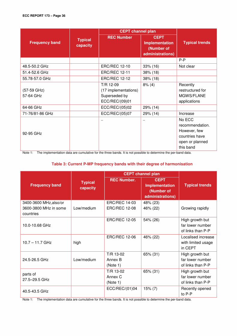
ECC REPORT 173 – Page 36
Frequency band Typical
capacity
CEPT channel plan
Typical trends
REC Number CEPT
Implementation
(Number of
administrations)
P-P
48.5-50.2 GHz ERC/REC 12-10 33% (16) Not clear
51.4-52.6 GHz ERC/REC 12-11 38% (18)
55.78-57.0 GHz ERC/REC 12-12 38% (18)
(57-59 GHz)
57-64 GHz
T/R 12-09
(17 implementations)
Superseded by
ECC/REC/(09)01
8% (4) Recently
restructured for
MGWS/FLANE
applications
64-66 GHz ECC/REC/(05)02 29% (14)
71-76/81-86 GHz ECC/REC/(05)07 29% (14) Increase
92-95 GHz
− − No ECC
recommendation.
However, few
countries have
open or planned
this band
Note 1: The implementation data are cumulative for the three bands. It is not possible to determine the per-band data.
Table 3: Current P-MP frequency bands with their degree of harmonisation
Frequency band Typical
capacity
CEPT channel plan
Typical trends
REC Number. CEPT
Implementation
(Number of
administrations)
3400-3600 MHz,also/or
3600-3800 MHz in some
countries
Low/medium
ERC/REC 14-03
ERC/REC 12-08
48% (23)
46% (22) Growing rapidly
10.0-10.68 GHz
ERC/REC 12-05 54% (26) High growth but
far lower number
of links than P-P
10.7 – 11.7 GHz high
ERC/REC 12-06 46% (22) Localised increase
with limited usage
in CEPT
24.5-26.5 GHz Low/medium
T/R 13-02
Annex B
(Note 1)
65% (31) High growth but
far lower number
of links than P-P
parts of
27.5–29.5 GHz
T/R 13-02
Annex C
(Note 1)
65% (31) High growth but
far lower number
of links than P-P
40.5-43.5 GHz ECC/REC/(01)04 15% (7) Recently opened
to P-P
Note 1: The implementation data are cumulative for the three bands. It is not possible to determine the per-band data.

ECC REPORT 173 – Page 37
In addition the implementation status within the CEPT was extracted from the ECO data base, where CEPT countries should enter the information about their adoption or not for each ECC Decision or Recommendation; however, not all administrations are efficient in providing their data.
It shows that, at the time of the publication of this report, most of the bands up to 38 GHz has a degree of harmonisation ranging from 45% to 67%; however, the relatively high number (in the order of 20% to 50%) of countries that have not given any information, prevent the possibility of a sounder analysis.
From the analysis of data in Table 2 and Table 3, it becomes obvious that the availability of CEPT channel arrangements becomes a powerful incentive for achieving wide spread European harmonisation of FS usage in a particular band.
In that respect, it might be also interesting to note how particular ERC/ECC Decisions and Recommendations in the FS field are implemented across CEPT countries. For this purpose Figure 24 and Figure 25 below show the number of CEPT administrations committing or planning to commit to certain ERC/ECC Decisions and Recommendations, which are most relevant for the planning of FS services. These data are based on the ECO implementation records, as valid for 1 October 2011. In Figure 26 you can find the situation for the Recommendation T/R 13-02 which shows the highest level of implementation throughout CEPT.
Figure 24: Implementation of some major ERC/ECC Decisions in the field of FS as of Sept 2011 (source: www.ecodocdb.dk)

ECC REPORT 173 – Page 38
Figure 25: Implementation of ERC Recommendations, which prescribe FS channelling as of Sept 2011 (source: www.ecodocdb.dk)
Figure 26: Implementation of ERC Recommendation T/R 13-02

ECC REPORT 173 – Page 39
5.3 BAND BY BAND ANALYSIS OVERVIEW
A band by band analysis has been performed based on the responses from the questionnaire. In general, FS deployment below 5 GHz indicate stable or no growth for P-P applications For all the frequencies there is a trend for increase except for the 31 GHz band being stable.
For further details see ANNEX 1: and a summary of the FS growth per band in Table 2 for P-P and Table 3 for P-MP.
5.4 BAND USAGE VS NUMBER OF LINKS IN OPERATION
The Following diagrams report the number of links declared in operations, according to the answers given.
Information take into account both P-P links and P-MP BS. Information on numbers of links in blocks of spectrum that has been auctioned have not been included in the totals.
5.4.1 Number of active links for each band
The following Figure 27 and Figure 28 compare the number of active links for each specific frequency band.
Figure 27: Distribution of links for the frequency bands from 0 to 25 GHz
Number of active links in Europe - mar 2011
1
10
100
1000
10000
100000
1000000
0,00 5,00 10,00 15,00 20,00 25,00 GHz
P-P
linksBS for
PMPc

ECC REPORT 173 – Page 40
Figure 28: Distribution of links for the frequency bands from 25 to 45 GHz
5.4.2 Hop length distribution
The following Figure 29 and Figure 30 show percentiles of hop length, as a function of frequency.
Figure 29: Typical hop length for frequency bands from 0 to 25 GHz (Distribution of hop length defined as “Typical” by European administrations)
Number of active links in Europe - mar 2011
1
10
100
1000
10000
100000
1000000
25,00 30,00 35,00 40,00 45,00 GHz
P-P
linksBS for
PMP
Hop lengths indicated as "Typical"
0
10
20
30
40
50
60
70
0,00 5,00 10,00 15,00 20,00 25,00 GHz
Km
0 %
10 %
30 %
50 %
70 %
95 %
100 %

ECC REPORT 173 – Page 41
Figure 30: Typical hop length for frequency bands from 25 to 45 GHz
Practically, the probability of a generic link, in X-axes frequency band, to be shorter then Y-axes values (km) can be determined by the parameter of the curve closest to the (X,Y) point.
The points above upper curve have probability = 1.
Answers by each administration have been given for three cases: minimum, typical and maximum length.
Although the “typical” case can be considered the most useful, distributions of lengths considered as minimum or maximum are useful for having a complete view of installations cases
5.5 CURRENT FS APPLICATIONS
This section analyses some of the most prominent applications in the Fixed Service. Although usage would vary between countries, it should be recognised that fixed links are also used by a large number of disparate users that make up a small percentage of the overall usage market when compared with mobile infrastructure e.g. the use of fixed links by local councils, utilities, emergency services etc.
5.5.1 Long-haul trunk/backbone networks
As reported in the 2002 in the ECC Report 003, Long-haul trunk networks are probably the oldest major application in the fixed service. Such trunk networks were originally used for transmission of long-distance telephone traffic between the regional switching centres within the national PSTN networks of incumbent telecom operators, also forming part of international connections. Usually such long-haul trunk networks were made of long chains of high-capacity links (often with several parallel channels, sharing a protection channel on n:1 basis), with a typical hop length of some 40-50 km and more. Later such chains were often completed to form several nation-wide rings for more adaptable and reliable routing of traffic.
Hop lengths indicated as "Typical"
0
2
4
6
8
10
12
14
16
18
20
25,00 30,00 35,00 40,00 45,00 GHz
Km
0%
10 %
30 %
50 %
70 %
95 %
100%

ECC REPORT 173 – Page 42
These backbone networks tend to be replaced by larger capacity fibre networks; unless where geographical remoteness still justify their permanence in service; only some connections (maybe with fewer channels) might remain as partial redundancy to fibre (e.g. for disaster relief).
On the other hand, newer networks, as used by mobile operators, have changed their deployment pattern following the introduction of densely deployed widely distributed mobile networks. They now have to provide many more densely located fixed links in complex chain/ring/star configurations. Therefore, frequencies used for these types of trunk networks have been or are going to be reused for networks now classified as “infrastructure support” (see next bullet) and used for the longer connections between big exchange centres.
It should be noted that backbone networks (but with far less capacity transported) are remaining in use for some “utilities” networks (typically for energy-related use), which, for safety reasons, prefer keeping a radio media alternative.
5.5.2 Infrastructure support networks
Infrastructure support networks of FS are usually used to provide connectivity between switching centres (one or several) and various nodes at different layers of telecommunications networks identified as Public Mobile Telephony Networks or FWA networks. Infrastructure support networks are distinguished from trunk network by presence of many layers and different connectivity configurations, which are ultimately formed by fixed links. Configurations of infrastructure support networks range from the chains connecting remote underlying network segments, nation-wide rings of backbone routing and combined ring/star networks for connecting many base stations (or other kind of bearer network terminal points) to regional switching or multiplexing centres. One simplified fragment of such infrastructure support network was given in Figure 1 of this report.
The growth of internal infrastructures of 2G/3G networks was required to support the permanent growth of subscriber bases, and as this still continues today, the infrastructure networks are also likely to grow further. This growth will continue and with the continuous expansion of mobile broadband networks (HSPA, HSPA+, LTE), further demand for infrastructure support solutions can be expected..
Wireless technology often provides a more practical and economic infrastructure alternative for quick roll out of networks such as mobile networks. The mobile networks already have to erect towers for their base stations at least every 20-30 km, in rural environment, and far more closer in more populated areas (down to few hundred meters are expected in dense urban areas); therefore, inter-connecting them with wireless FS only adds the cost of the FS terminal equipment to the overall cost. On the other hand, laying down fibre or cable links demands much more additional work and costs. Therefore, fibre only become viable when the payload capacity collected and aggregated in the mobile network has grown significantly to the level, where wireless infrastructure links cost may become comparable or they have reached their capacity limits (which is, however, also extending up and up approaching the gigabit/system). But this usually happens only for core layers.
5.5.3 Fixed Wireless Access networks
Fixed Wireless Access (FWA) networks are designed to provide a direct connection between the Customer Premises Equipment (CPE, essentially user terminal or data servers) and an operator’s core network (PSTN network, data communication network). FWA normally uses P-MP radio technology to serve a large number of CPEs within the coverage area of a central station, as was illustrated in Figure 3. Thus, FWA essentially applies the principle of a cellular network, already well-established in mobile communication networks, into a fixed service scenario.
FWA is also aiming at providing access solutions capable of provisioning truly broadband (multimedia) services to end-customers. Therefore FWA networks capable of providing broadband services are also sometimes called Broadband Fixed Wireless Access (BFWA).
The scope of FWA in the bands around 3.5 GHz and below was to provide basic narrow-band telecommunication services (telephony, Internet access at ISDN data rates) to customers, which could not be reached economically by other media or those served by non-incumbent operators, having no copper infrastructure in place. However, the rapid evolution of technologies supporting both fixed and mobile
ECC REPORT 173 – Page 43
applications (e.g. WiMAX) has, de facto, realised the convergence of FWA and MWA into what is now called Broadband Wireless Access (BWA defined by ECC/DEC/(07)02).
In the higher bands (10 GHz, 26 GHz and above) the original scope of FWA, as depicted in late 1990’s, was to provide basic telephony, but also high bit rate data services (anything up to 2 Mbit/s and above) for Internet access, video conferencing, interactive multimedia services (e.g. video on demand, etc.).
However, although FWA is in principle well suited for serving any customers, ranging from residential to small businesses (SOHO/SME) and large corporations, the analysis of current market situation shows, that “pure” FWA operators have today less and less hope to make profitable business plans by serving residential customers. After residential access (including ISDN and broadband DSL services) prices were driven down by competition and by the advent of efficient BWA in lower bands, it became extremely hard for FWA to compete in residential market because of still high CPE pricing.
Therefore, FWA networks in these higher bands are confined in niche deployments and no real expansion is expected. In particular, the band 40.5-43.5 GHz designated in 1999 by CEPT for MWS, and mostly unused since then, has been re-designated also for PP links use (see ECC/DEC/(99)15 revised 2010). Other bands used for FWA in a few European countries are mostly those below 3 GHz (around 1.5 GHz and 2-2.7 GHz), however they are used on a very limited national basis only.
5.6 TRENDS IN FS APPLICATIONS
The information gathered for developing the present Report gives the evidence that the current trends in the FS market place are for an ever increasing provision of high bandwidth capacity for the mobile networks infrastructures. These very high capacity links are able to provide a viable alternative to deploying fibre optic cable especially in rural areas but equally in high density urban areas where there would be severe disruption caused by digging up roads etc. to lay down fibres.
FWA applications are either stable/decreasing in higher frequency bands or migrating to converged BWA networks in bands at around 3.5 GHz or below.

ECC REPORT 173 – Page 44
6 CONCLUSIONS
The Fixed Service is and remains a key service for telecommunication infrastructure development. Since 1997 the CEPT has provided public information to present a picture of the FS deployment in Europe with the intention to be use it as a reference and for guidance purposes for administrations, operators and manufacturers.
In 2010, the ECC decided to start the edition of a new report as an updated version of the ECC Report 003 (published in 2002), in order to verify the assumptions of the previous studies and to collect updated information on the number of fixed links for each band in CEPT countries. Therefore, this report builds on the results of the original ERO Reports on FS trends post-1998 and post-2002 by revising it and updating the information on FS use.
Developments in the technologies show the new trends in the FS sectors: ranging from higher modulation schemes (up to 1024 levels), adaptive modulation schemes to Hybrid/Ethernet technology equipment, better suited for different QoS levels and high capacity links.
FWA applications are either stable/decreasing in higher frequency bands or migrating to converged BWA networks in bands at around 3.5 GHz or below.
The information gathered for developing this report gives the evidence that the current trends in the FS market place are for an ever increasing provision of high bandwidth capacity for the mobile networks infrastructures. These very high capacity links are able to provide a viable alternative to deploying fibre optic cable especially in rural areas but equally in high density urban areas where there would be severe disruption caused by digging up roads etc. to lay down fibres.
As a consequence the report highlights the strategic importance of some frequency bands for the FS. Some of these bands have already started to show a rapid growth in terms of number of links (13 GHz, 15 GHz, 18 GHz, 23 GHz, 38 GHz), and on which special attention from administrations should be taken; while others are still preparing to take off (32 GHz, 50 GHz, 70/80 GHz, 92 GHz). In addition, the potentially interesting issue of NLOS urban backhauling for the new generation of mobile networks might open for new applications also in FS bands below about 6 GHz.
This report highlights also the fact that the CEPT proactively responds to the industry demand for efficient usage in the new millimetric wave bands with a set of new or revised recommendations. In term it creates a healthy competitive FS environment with wider harmonisation use of FS. As part of the development strategies, the CEPT, in 2011, revised the recommendation on the usage of the band 7125-8500 MHz with a view to harmonise its use in Europe for countries that are in a position to refarm, as it is the only FS band lacking harmonisation incentives (in terms of clear CEPT policy and/or channel arrangements).
Regarding the assignment procedures used, the responses show that for P-P links the most used method foresees conventional link-by-link license and centralised coordination. However, assignment/auction of frequency blocks in certain bands becomes also popular; this is particularly true when also P-MP (or, in some cases, even mixed FS and other telecommunication service) are permitted.

ECC REPORT 173 – Page 45
ANNEX 1: BAND BY BAND REVIEW OF THE FS USAGE
This annex presents a deeper band by band analysis extracted from the replies to the questionnaire.
A.1.1 FREQUENCIES BELOW 2 GHz
This frequency range is used by many applications, mostly related to mobile world (IMT, GSM 900/1800, UMTS, HSPA, LTE, etc.). However the answers to the Questionnaire indicate that also P-P applications exist in almost all countries and very low level of harmonisation. The only harmonised bands for FS below 2 GHz are: 1350-1375 MHz paired with 1492-1517 MHz and 1375-1400 MHz paired with 1427-1452 MHz which are using the Recommendation T/R 13-01 Annexes A and B. Some P-MP applications have been reported by some administrations. However, these latter bands, even if providing limited bandwidth, might be potentially suitable for NLOS backhauling applications (see section 4.1.3).
A.1.2 2.025 – 2.4 GHz BAND
This frequency range is available for many applications, mostly related to mobile service (IMT, MSS and so on).About 1000 links have been indicated in operation in addition to about 120 base stations.
The answers to the Questionnaire indicate that applications for P-P exist in about 30 countries, where CEPT Recommendation T/R 13-01 is the most frequently referred channel plan.
Few countries indicated the existence of a national plan. The use of this band for the fixed service seems to be in reduction or stable in almost all countries. However, the 2 GHz band (CEPT Recommendation T/R 13-
01 Annex C), providing ~ 80 MHz of paired bandwidths (presently up to 5 × 14 MHz paired channels), might be potentially suitable for NLOS backhauling applications (see section 4.1.3).
A.1.3 3.4 – 4.2 GHz BAND
This frequency range is available for IMT (3.4-3.6 GHz as established by WRC-07) and P-MP applications (3.4-3.8 GHz), including WiMAX, as well as Fixed Service P-P traditional applications. The 3.4-3.8 GHz band is also addressed by the European Commission Decision 2008/411/EC where neutrality with regard to technology and service is required. While the first is growing very rapidly, the latter is decreasing. The results of the Questionnaire for the whole 31 CEPT countries indicated more than 15500 base stations in operation, in addition to about 6500 P-P links. The number of BS is well underestimated, as block and link based licenses are foreseen in many countries. The great majority of countries refer to ERC/REC 12-08, few administrations refer to a national frequency plan.
It should also be taken into consideration that the portion 3.8-4.2 GHz (ERC/REC 12-08 Annex B part 1),
providing up to 6 × 29 MHz paired channels, might be potentially suitable for NLOS backhauling applications (see section 4.1.3); However, sharing with FSS should be carefully considered.

ECC REPORT 173 – Page 46
Figure 31: Trend for the P-P and P-MP (in this case only BS are counted) links in the band 3.4-4.2 GHz in the 19 CEPT countries available for comparison
A.1.4 4.4 – 5 GHz BAND
This band appears scarcely used for P-P links. Some links were reported in Hungary (140 links), in Spain (322 links) and in the Russian Federation (350 links).
FS Military use is noted in some countries.
A.1.5 5.725 – 5.95 GHz BAND
The band is unlicensed/light licensed, from 5.725 to 5.850 GHz.
From 5.85 to 5.95, some use is indicated, mostly for P-MP. The licensing regime appears to be mostly link-based. Few countries indicated a significant use, including the Russian Federation (1400 P-P links, 600 P-MP Base Stations, infrastructure and broadcasting).
National frequency plans have been declared in majority of answers.
A.1.6 5.9 – 7.1 GHz BAND
This frequency range is used in Europe for high capacity P-P links, in accordance with the frequency plans contained in the ERC/REC 14-01 and ERC/REC 14-02, mainly forming part of fixed and mobile and broadcasting infrastructure.
After a negative trend towards the end of the 20th century, mainly due to the migration from analog to digital links, the trend from the 2010 questionnaire has changed from 2001 report and seems to show a stable situation for the two bands, as indicated in the figure below.

ECC REPORT 173 – Page 47
Figure 32: Trend for the P-P links in the band 5.9-7.1 GHz in the 19 CEPT countries available for comparison
The results of the questionnaire for the whole 31 CEPT countries indicated 20242 links declared active in this range, which has been traditionally used for P-P links since quite a long time.
Significant number of countries indicates a moderate trend to increase the usage of this range in the years to come (10 to 30% increase), some report even a higher percentage, some other indicate the band is congested or close to congestion.
95% percentile of hop length indicated as “typical” is 55 km (36 km for those indicated as “minimum”).
The Russian Federation has indicated a use for P-MP applications, with about 2000 base stations in operation. Lithuania indicated a trend for 5.9-6.4 GHz to be used for mobile applications in the future.
A.1.7 7.1 – 8.5 GHz BAND
About 38500 P-P links have been declared active in this range, which is also an historical band for P-P applications.
The great majority of countries refer to high and medium capacity, link based license, mainly forming part of fixed and mobile infrastructure; broadcast infrastructure is also involved.
Frequency use in this band appears very complicated, due to the fact that use has started quite long time ago, with analogue systems, and many countries adopted national plans at that time, without coordination with other countries.
In later times, most of used channel rasters have been incorporated in ITU-R Recommendations, but no frequency harmonisation was possible, since equipment were already in operation. Nevertheless in 2011 the ECC/REC/(02)06 was revised with a view to harmonise the use of the band in Europe for countries planning to refarm.
Military use has been also reported, (7.25-7.3 GHz, 7.25-7.75 GHz (NATO), 7.9-8.4 GHz (NATO)); emergency services (7.125-7.425 GHz) are allocated in Hungary. Further details on military usage of this band can be found in the ECC Report 163.
Significant number of countries plan to increase the usage of this range (10 to 30% increase), some indicate even a higher percentage, no major congestion is reported. The comparison analysis with previous reports seems to show an overall stable situation in the band, as presented in.
95% percentile of hop length indicated as “typical” is 53 km (21 km for those indicated as “minimum”).

ECC REPORT 173 – Page 48
Figure 33: Trend for the P-P links in the band 7.1-8.5 GHz in the 19 CEPT countries available for comparison
A.1.8 10 – 10.68 GHz BAND
About 3900 P-P links have been declared active in this range, together with about 1900 base stations (1500 in the Russian federation). 95% percentile of hop length indicated as “typical” is less than 40 km (25 km for those indicated as “minimum”).
All range of capacities are reported in this band. 60% of the links are individually licensed, forming part of infrastructure for mobile and broadcasting networks.
Frequency allocation is practically based on CEPT Recommendation ERC/REC 12-05 (and annexes) while the ECC/DEC/(10)01 regulates the sharing condition between FS, MS and EESS; in addition, some national plans (Serbia, Luxembourg, Greece and Ireland) exist.
Need for growth has been indicated by few countries; few analogue links still operating (Slovenia) will be switched off, in order to reuse frequencies for BWA. The band is not congested. A comparison of the number of links between P-P and P-MP is shown below.
Figure 34: Trend for the P-P and P-MP links in the band 10-10.68 GHz in the 19 CEPT countries available for comparison

ECC REPORT 173 – Page 49
A.1.9 10.7 – 12.5 GHz BAND
About 9300 P-P links are in service in this range, allocated many years ago to P-P links. In 10.7 – 12.5 GHz some P-MP base stations are reported, mainly in Hungary (about 150 base stations in total). 95% percentile of hop lengths indicated as “typical” is 40 km (33 km for those indicated as “minimum”).
Figure 35: Trend for the P-P and P-MP links in the band 10.7-12.5 GHz in the 19 CEPT countries available for comparison
The majority of applications consist of high capacity links, individually licensed, forming part of telecommunication and broadcasting infrastructure networks.
Frequency usage refers to CEPT ERC/REC 12-06, as long as Recommendation ITU-R F.387, with few national plans.
Many countries intend to increase the use in next years (10-30% increase) and in one country (Italy) it appears to be already congested. The comparison chart shows an overall stable situation, as reported in Figure 35. It has to be noted that due to satellite sharing problems, some countries have stopped the introduction of new links in this band (see ERC/DEC/(00)08).
A.1.10 12.75 – 13.25 GHz BAND
About 57600 P-P links are in operation in this range. 95% percentile of hop length indicated as “typical” is 25 km (11 km for those indicated as “minimum”).
The major utilization is for medium-high capacity links, individually licensed, most of them belonging to fixed, mobile and broadcast infrastructure.
The frequency usage refers to CEPT ERC/REC 12-02.
Regarding the usage, several countries indicate expectations to moderate increase in coming years (5-30% increase). Nevertheless congested situations are reported by many administrations. The comparison chart shows a continuous increase trend since 1997, as illustrated in Figure 36.

ECC REPORT 173 – Page 50
Figure 36: Trend for the P-P links in the band 12.75-13.25 GHz in the 19 CEPT countries available for comparison
A.1.11 14.25 – 15.35 GHz BAND
About 1500 P-P links have been declared in 14.25-14.5 GHz band. The use of this band by the FS is limited to few countries (Cyprus, France, Italy and the Russian Federation). In the UK and France the 14.25-14.5 GHz band is closed to new fixed links. In 2011, around 300 existing links are still in use in each country.
On the contrary the band 14.5-14.63 paired with 15.23-15.35 GHz is heavily used all over Europe with about 49000 links declared active in this range. P-P links only were reported.
Major utilization is for low-medium capacity links, although a significant percentage assigned to high capacity use have been also indicated.
Links appear individually licensed, most are part of fixed and mobile infrastructure.
Frequency use refers to CEPT ERC/REC 12-07. Sweden refers to a national plan, while in Italy both CEPT channel plan as well as a national plan in the center band are reported.
About 10 countries indicate use growth in next years (5-30% increase), while congestion is declared by 6 administrations. Some other countries indicate use (or trend) for fixed satellites applications. The comparison charts for the band 14.25-14.5 GHz and 14.5-15.35 GHz are presented in Figure 37 and in Figure 38.
95% percentile of hop length indicated as “typical” is 23 km (12 km for those indicated as “minimum”).

Figure 37: Trend for the P
Figure 38: Trend for the P
A.1.12 17 – 17.7 GHz BAND
Band is practically not used. Only 33 links declared in operation
A.1.13 17.7 – 19.7 GHz BAND
Heavily used historical P-P FS band with about hop length indicated as “typical” is about 20 km (9.5 km for those indicated as “minimum”).
The major utilization is for high capacity links, with a comparable usageapplications. Most links are individually licensed, majority is allocated to fixed and mobile infrastructure.
The channel plan is based on the CEPT ERC/REC 12arrangements are used for low capacity.
Trend for the P-P links in the band 14.25-14.5 GHz in the 19 CEPT cavailable for comparison
Trend for the P-P links in the band 14.5-15.35 GHz in the 19 CEPT cavailable for comparison
Band is practically not used. Only 33 links declared in operation in Italy, with national frequency plan.
FS band with about 90000 links appear on field in this range.hop length indicated as “typical” is about 20 km (9.5 km for those indicated as “minimum”).
The major utilization is for high capacity links, with a comparable usage of medium applications. Most links are individually licensed, majority is allocated to fixed and mobile infrastructure.
The channel plan is based on the CEPT ERC/REC 12-03 for medium and high capacity; several national capacity.
ECC REPORT 173 – Page 51
14.5 GHz in the 19 CEPT countries
15.35 GHz in the 19 CEPT countries
in Italy, with national frequency plan.
links appear on field in this range. 95% percentile of hop length indicated as “typical” is about 20 km (9.5 km for those indicated as “minimum”).
of medium and low capacity applications. Most links are individually licensed, majority is allocated to fixed and mobile infrastructure.
03 for medium and high capacity; several national

ECC REPORT 173 – Page 52
Concerning the usage, significant increase expectations in next years (5-30% increase) are foreseen in about 21 countries, although a moderate situation of congestion is already reported. The comparison chart is reported in Figure 39.
Figure 39: Trend for the P-P links in the band 17.7-19.7 GHz in the 19 CEPT countries available for comparison
A.1.14 21.2 – 22 GHz BAND
Poorly used P-P band. About 900 links are active in this range in 6 countries only (some of them are legacy links). Most hop length indicated as “typical” is below 5 km (3 km for those indicated as “minimum”).
Links appear mostly low-medium capacity. Frequencies are used according to Recommendation ITU-R F.637 or local national plan.
Very limited expectation to increase is reported in 1 country, although a moderate situation of congestion is reported somehow (Cyprus, Hungary).
A.1.15 22 – 23.6 GHz BAND
This is a heavily used historical P-P FS band, with a total of about 115000 links for most of the countries who responded to the questionnaire. Numerically, 95% percentile of hop length indicated as “typical” is about 14 km (3 km for those indicated as “minimum”).
All capacities are reported, most being individually licensed, majority of them is allocated to fixed and mobile infrastructure.
The channel plan follows the CEPT T/R 13-02. This Recommendation was updated in 2010 to introduce additional channel arrangements in the centre gap.
Concerning the usage, significant increase expectations in the next years (10-50% increase) are reported in about 20 countries (just 2 indicating a decrease).Congestion is reported by about 10 administrations.

ECC REPORT 173 – Page 53
Figure 40: Trend for the P-P links in the band 22-23.6 GHz in the 19 CEPT countries available for comparison
Great majority of administrations declare mean length below 7 km, although some countries indicate typical length greater than 10 km. The comparison chart is reported in Figure 40.
A.1.16 24.2 – 24.5 GHz BAND
This band is poorly used (10 administrations gave an answer), less than 100 links, both for P-P and Base Stations, have been declared. Licensing regime appears link by link or block based, in relation to use (P-P or P-MP).
Recommendation ITU-R F.748, CEPT Report 38 and national plans have been indicated.
A.1.17 24.5 – 26.5 GHz BAND
A total of about 37000 links and 2259 P-MP Base Stations are in service in more than 30 countries. 95% percentile of hop length indicated as “typical” is about 9 km (4.8 km for those indicated as “minimum”).
Figure 41: T rend for the P-P links in the band 24.5-26.5 GHz in the 19 CEPT countries available for comparison

ECC REPORT 173 – Page 54
Medium and high capacity links are reported, but significant attention to low capacity is also noticeable.
Licenses are assigned by blocks or by link, according to the use. The majority of links is allocated to fixed and mobile infrastructure.
The P-P channel plan follows the CEPT T/R 13-02.
The P-MP channel plan reported is the ERC/REC/(00)05 now superseded by the ECC/REC/(11)01.
Concerning the usage, significant increase is expected in the next years (10-30% and even more in some countries) by more than 20 administrations (no indication of decrease).Congestion is already reported by a few administrations.
The comparison chart is reported in Figure 41.
A.1.18 26.5 – 27.5 GHz BAND
Very limited use (30 links reported) is declared for this band, used for military/NATO needs also.
Licenses are assigned by blocks or by link, according to the use, majority of links is allocated to network infrastructure.
Frequencies are used according to Recommendation ITU-R F.748.
No expectation to increase the use in next years is envisaged.
A.1.19 27.5 – 29.5 GHz BAND
Figure 42: Trend for the P-P links in the band 27.5-29.5 GHz in the 19 CEPT countries available for comparison (this does not include numbers of p-p links in auctioned blocks)
2600 links and about 380 P-MP Base Stations are reported in 31 countries. It has to be noted that in many countries the block allocation does not require any link notification. Therefore the figures provided for this kind of band could be well underestimated. 95% percentile of hop length indicated as “typical” is about 4 km (2.5 km for those indicated as “minimum”).
Use for medium and high capacity is mostly reported.

ECC REPORT 173 – Page 55
Licenses are assigned by blocks or by link, according to the use; majority of links is allocated to fixed and mobile infrastructure.
The P-P channel plan follows the Recommendation T/R 13-02.
The block assignment guidance for P-MP links is provided in the ECC/REC/(11)01.
9 countries indicate expectations to increase the use in next years (10-0%; Finland indicates 90%), no one indicate decrease, local congestion is reported by Finland. The comparison chart is presented in Figure 42.This band has been segmented between FS and uncoordinated FSS usage with the ERC/DEC/(05)01. The majority of CEPT administrations have implemented this Decision.
A.1.20 31 – 31.3 GHz BAND
Very limited use is indicated for this band, with very few indications (9 administrations out of 31).
Licensing regime appears link-by-link.
The channel plan follows ECC/REC/(02)02, in addition to national plans.
No significant expectations to increase the use in next years are reported.
A.1.21 31.8 – 33.4 GHz BAND
Around 8000 links are active in the 31 countries as indicated in Figure 43. 95% percentile of hop length indicated as “typical” is about 3.54 km (0.5 km for those indicated as “minimum”).
Use appears mostly for medium and high capacity.
Licenses are assigned mostly by link, although block allocation has been reported by few administrations.
The P-P channel plan follows the ERC/REC/(01)02.
Figure 43: Trend for the P-P links in the band 31.8-33.4 GHz in the 19 CEPT countries available for comparison (this does not include numbers of P-P links in auctioned blocks)
Even though no P-MP links were reported, the block assignment guidance for P-MP links is provided in the ECC/REC/(11)01.

ECC REPORT 173 – Page 56
10 countries expect an increase in the usage in coming years (10-50% and more; Finland, Slovakia and Lithuania indicates 100%). No indication of decrease has been reported. Congestion is reported by one administration.
A.1.22 36 – 37 GHz BAND
Only the Russian Federation indicated the usage of this band, reporting 132 links in operation, P-P, with licensing regime for link and for blocks.
The channel plan is given in the Recommendation ITU-R F. 749.
A.1.23 37 – 39.5 GHz BAND
Heavily used historical P-P FS band with about 136000 links in use, by most of the CEPT countries.
All capacities are reported, individually licensed (5 answers indicated that a portion of the band is used with block licenses); great majority of links is allocated to fixed and mobile infrastructure.
Frequencies are utilized according to Recommendation T/R 12-01.
Concerning the usage, increase in the use of the band is reported in coming years (10-50% increase) in 18 countries (no one indicate decrease). Congestion is already reported by 4 administrations. The comparison chart is reported in Figure 44.
95% percentile of hop length indicated as “typical” is about 5 km (1 km for those indicated as “minimum”).
Figure 44: Trend for the P-P links in the band 37-39.5 GHz in the 19 CEPT countries available for comparison
A.1.24 40.5 – 43.5 GHz BAND
This band has been opened to P-P applications in 2010. Therefore it is just at the beginning of its use (about 100 links have been declared active).
Of the 31 countries that have answered the Questionnaire, 12 foresee use or have just started.
Individually license and block license are present, and both P-P and P-MP are foreseen, great majority of links are addressed to network infrastructure.

ECC REPORT 173 – Page 57
The channel plan follows the ERC/REC/(01)04 as amended in 2010.
Few indications are given on hop length, although an indication is given from the Russian Federation for a 3 km max hop.
A.1.25 48.5 – 50.2 GHz BAND
Although quite limited use is indicated for this band, no active links have been declared by the about 10 administrations who answered on this band.
Planning is for a P-P use belonging to fixed and mobile network infrastructure, with licensing regime mostly based on a link by link assignment.
The channel plan follows the ERC/REC 12-10.
No significant expectations to increase the use in next years are reported.
A.1.26 50.4 – 51.4 GHz BAND
Very limited use is indicated for this band, with very few indications (4 administrations out of 31).
One link only is reported in use in Denmark.
No significant expectations to increase the use in next years are reported.
A.1.27 51.4 – 52.6 GHz BAND
This band, available for P-P applications, is almost empty with the exception of the 837 links in Switzerland.
Links appear block licensed there, while majority of answering countries gave indication for link-based license.
Majority of answers relate to allocation for network infrastructure.
The channel plan follows the Recommendation T/R 12-11.
3 countries report expectations to increase the use in coming years.
A.1.28 55.78 – 57 GHz BAND
No active links have been indicated. Form the replies to the questionnaire it seems that the planned licensing regime will be mostly link based and the band should be used for fixed and mobile infrastructure.
The channel plan follows the Recommendation T/R 12-12.
Concerning the usage of the band, expectations to increase the use in coming years are reported by few countries. There were indications that no equipment is available in 2011.
A.1.29 57 – 64 GHz BAND
The channel plan for part of this band (57-59 GHz) used to follow ERC/REC 12-09. This was superseded by the new Recommendation ECC/REC/(09)01 which combines the whole 57-64 GHz range specifically for P-P application with Multi Gigabit Wireless Systems (MGWS) following ERC Recommendation 70-03 and EN 302 567.

ECC REPORT 173 – Page 58
Around 700 links are in use in this band in few countries according to the old Recommendation.
Almost all capacities have been reported, most being licensed on a link by link basis (7 answers), but some administrations foresee also block license (4 answers).
In Lithuania, Sweden, Slovenia, UK and Germany the band is unlicensed.
Great majority of links is allocated to fixed and mobile infrastructure.
Concerning the usage, new equipment following the new Recommendation are becoming available and one link is already reported in Norway. Other should follow.
It shall be noticed that band 59 to 61 GHz can be used for NATO/military applications also, as well as for SRD (ISM possible in 61-61.5 GHz).
A.1.30 64 – 66 GHz BAND
Only one link in the UK was reported in this band.
Apart from Lithuania, indicating unlicensed regime, a trend for a link by link authorization regime can be referred.
Foreseen application for high capacity P-P links is reported.
The frequency band is used according to the ECC/REC/(05)02.
SRD use have also been indicated, with potential openings and lack of equipment.
A.1.31 71 – 76 GHz / 81 – 86 GHz BAND
In some countries part of the band (71-74/81-84 GHz) is reserved for military use (NATO).
The use of this band is recent and starting now. 149 links are in use. Typical lengths from 1 to 2 km have been indicated. However a link length up to 7 km was also reported.
Most answers relates to link by link licensing regime, with the exception of Norway (both link by link and block based) and Lithuania (unlicensed), Sweden, UK and Czech Republic for light-license. Most applications are foreseen for P-P links used for fixed and mobile infrastructure, and some test links are going on (e.g. Germany).
The referred Recommendation for this band is ECC/REC/(05)07.
Portugal reported use also for SRD.
A.1.32 92 – 95 GHz BAND
Only 3 links in Czech Republic have been indicated. Two administrations referred of link by link licensing regime, while the Russian Federation indicated preference for unlicensed use. Most applications are foreseen for high capacity P-P links used in support of the fixed and mobile infrastructure.
In 2011 a preliminary draft new recommendation for the use of this band is under development in ITU-R.
National frequency plan has been indicated by Ireland.

ECC REPORT 173 – Page 59
ANNEX 2: NATIONAL EXAMPLES OF REGULATING FIXED SERVICE
A.2.1 FRANCE
A.2.1.1 Overview
In France, the overall frequency management responsibility (in particular international policies and frequency co-ordination) fall into the hands of Agence Nationale des Fréquences (ANFR). However the authorisations for telecommunication activities, including authorisations for civil use of the radio spectrum, are issued by the Autorité de Régulation des Communications Electroniques et des Postes (ARCEP)), the independent regulator set up in January 1997.
The ARCEP is therefore responsible for co-ordination and assignment of frequencies for public and private network operators and then for issuing appropriate licences for operators. ARCEP manages, amongst others, the following FS frequency bands: 1.5, 3.5, 4, 6, 7-8, 11, 13, 18, 23, 26, 28, 32, 38, 71-76/81-86 GHz.
Regularly, ARCEP updates the strategy for the use of the different frequency bands allocated to the FS. These guidelines are defined in relation and with the co-operation of all the different actors involved (ARCEP web site: http://www.arcep.fr/).
The fixed link assignment system that has been developed by the ARCEP is efficient in meeting the demands of customers. The ARCEP has developed an exchange format to handle electronic licence application, which has reduced significantly the treatment time for fixed link assignments, which is now less than 2 months. In some bands, certain “preferential channels” are assigned to specific operators, where they can deploy their P-P FS links in a more flexible way.
Generally speaking, the use of fixed links is closely linked to the evolution of the international regulation (such as the frequency bands allocations in the ITU RR, the adoption of relevant ERC Recommendations or Decisions). Such modifications may sometimes lead to the necessity of band refarming, recently becoming a familiar process for the French telecommunication users.
The regulation has also to take into account the recent arrivals of the new players in the FS field. New operators are being authorised by the ARCEP according to two classes of networks given by the French Law: the class L33-1 applies for networks open to public and the class L33-2 applies for private networks. The range of telecom operators include: the incumbent operator (obligations of public service), operators of public mobile networks, operators of private mobile networks (PMR, PAMR, etc.), operators of FWA networks, the incumbent broadcasting operator, FM broadcasting operators and about 250 users of private FS networks. These telecom operators come in addition to the governmental users, who obtain frequency spectrum through the offices of Prime Minister and do not need authorisation from the ART.
The FS frequency bands, as designated in the French National Frequency Allocation Table, may be thus used by both the civil companies authorised by the ARCEP and by governmental bodies.
A.2.1.2 Co-ordination with other services and organisations
International co-ordination processes are dealt with by the ANFR, especially when satellite services are involved.At the national level, the co-ordination is also dealt with by the ANFR through a consultation process between all the concerned user groups so as to respect the interests of the existing users while ensuring, to the greatest extent, an access to the spectrum required for the new ones.
A.2.1.3 Spectrum pricing
At the moment in France only civil telecom operators have to pay fees for using the spectrum. An administrative incentive pricing system applies to the FS, this meaning that the fees depend on the bandwidth, the frequency band used by the operator and the spectrum efficiency. The bigger is the bandwidth, the higher are the fees; the higher is the frequency band, the lower are the fees.

ECC REPORT 173 – Page 60
A.2.1.4 Spectrum refarming
In France, a procedure for spectrum refarming is based on statutory texts and had been used in practice already for several years. This procedure is based on a sound economic approach and makes it possible to meet the demands of operators in the sector. Furthermore, it does not call into question the procedures for attribution and assignment of frequencies that are laid down at international level by the ITU and the CEPT and at national level by the regulatory authorities.
The spectrum refarming procedure establishes evaluation of the cost of the refarming and the management of a fund needed to finance this refarming.
The user who is to leave a frequency band usually receives compensation. This often takes the form of a financial contribution and assignment of frequencies in alternative frequency band, except when a wire-based technology may be used as a substitute. This compensation process is discussed by all concerned parties within a specific advisory commission, set up by the ANFR to deal with the financial aspects of spectrum refarming: the Refarming Commission.
Moreover, in France, the State plays the role of intermediary by initially financing from the state budget the relocation of old services, with subsequent reimbursement of these funds from the new users of refarmed spectrum once they have obtained their demanded frequencies. An intermediary role played by the State makes it possible to increase significantly the speed of refarming process, by making the spectrum freed exactly in time when it is needed for new users.
The ANFR has also set up a commission to study the cases where the international obligations accepted and adopted by the French Administration lead to the necessity of changing, usually in a shorter term than the usual life-time of the equipment, the use of a part of the spectrum.
Normally the cost of refarming depends on the necessary speed of the replacement of old equipment and the cost of new, replacing equipment. This cost is ultimately beared by the new users of the spectrum to the extent possible.
Recently, the identification of frequency bands for the IMT-2000/UMTS has led to the necessity of removing a great number of fixed links, belonging to France Telecom and Ministry of Defense, from the bands, designated to future operators of the 3
rd generation of the Public Mobile Networks. The estimated cost of this
refarming project is 38 million EUR.
A.2.2 HUNGARY
A.2.2.1 General FS trends
As a general rule the radio links in Hungary widely use digital technologies.
The high-capacity microwave backbone networks operating at lower frequencies (in the 4 GHz, L6 GHz, U6 GHz, 11 GHz bands) are losing ground to optical cable transmission. High-capacity networks operating at 18 GHz are mostly used by the mobile carriers to link in a chain the base stations (with SDH/ATM technology) and connect them to the switching center. Further growth is anticipated in the latter area.
P-MP system licenses were allocated through auctions in the 3.4 GHz band, meeting the current demand.
However it is expected that an extension of allocated band will be required later. The possible options are the 3.7 GHz, the 26 GHz and the 32 GHz bands.
The MVDS system for TV program distribution now covers Budapest and operates in the 12 GHz band to meet an essential demand for residential sector.

ECC REPORT 173 – Page 61
A.2.2.2 Basic principles of national regulation for FS bands
� National regulations are fundamentally based on the relevant ECC Decisions and Recommendations. � The complete frequency band 10-10.68 GHz is designated exclusively for ENG/OB. � In the 26 GHz frequency band the primary trading of the frequency blocks is currently being under
preparation. Point-to-point and point-to-multipoint systems can be realized in correspondence with the licensees’ demands. These systems may be used either for general purpose or fixed wireless access and might support the infrastructure of mobile networks. Technology - and service - neutrality is ensured in this band.
� In Hungary the entire 28 GHz band is allocated to Fixed Satellite Service without any segmentation (FS is not allowed in this band).
� There are two options of channel arrangement regarding the 31 GHz band to meet the market demand: o Option 1: 31-31.3/31.5-31.8 GHz with 514 MHz duplex space o Option 2: 31-31.3 GHz with 140 MHz duplex space
For the time being, the Option 2 has not been implemented yet, the introduction is planned. � The frequency band 57.1-58.9 GHz is designated for systems that use Listen Before Talk technique.
Technical planning is not required for these systems. � Online registration is planned to be introduced in the frequency band 59-64 GHz. � Development of the online registration system in the frequency band 71-76/81-86 GHz is in progress.
A.2.2.3 Avoidance of shared use by several radio services
The relative richness of the Hungarian spectrum for the fixed service makes it possible to develop such spectrum policy that reduces the chance of conflicts due to interference with the fixed satellite service.
In several frequency bands the fixed service enjoys priority over the satellite services. In other bands the satellite services have priority, but this does not go to the detriment of the fixed service in view of the relative richness of the spectrum.
A.2.2.4 Fixed service preferences
The following describes several cases where FS are given specific priority over other services:
� VSAT deployment is not allowed in the satellite C-band. This measure provides protection for the 4 GHz, L6 GHz and U6 GHz high-capacity RRL networks;
� No satellite earth stations are allowed in the 14.5-14.9 GHz band in order to protect the RRL networks at 15 GHz;
� The earth stations of the 18.8-19.3 GHz NGSO systems cannot get protection from the fixed service. It can be ensured in this way that later applications must not restrict the operation of the RRL networks at 18 GHz.
A.2.2.5 Open data access
The radio engineering and deployment parameters of the RRL frequency assignments connections are openly available public information in Hungary, so they can not constitute a business confidentiality. The Authority provides data for the affected parties for the design of radio connections. These data also cover the interference environment, which must be taken into consideration in the design phase.
A.2.2.6 Operator planning, authority control
In Hungary, the radio networks are designed by the applicants, or the applicants hire third party designers for the job. Only professionals with authority licence may perform design work. The designer carries extensive responsibility in the respect of the interference calculations. After planning, the authority granting the licence is entitled to check the plans.
A.2.2.7 Methods of frequency allocation
The frequencies for cellular P-MP FS systems are considered to be a limited resource. The form of the procedure of primary trading can be auction or beauty contest. In the 3.5 GHz band five national coverage
ECC REPORT 173 – Page 62
frequency blocks had been auctioned. In the 3.7 GHz band, assignment of frequency blocks is expected also through an auction. For the 26 GHz frequency band, the beauty contest is under preparation.
From the point of view of frequency use, the frequencies for P-P FS systems can not be regarded as limited resource, therefore applications for P-P FS are treated on a first-come-first-served basis.
A.2.2.8 Frequency fees
In Hungary, frequency fees are charged on the use of the frequencies. The fee consists of two components:
� one-time frequency occupancy fee; � monthly frequency usage fee.
The amount of the fees payable for different radio applications (also in the case of FS) is determined by legal rules. The frequency fee has a general regulatory and a highly useful measuring/evaluating function.
A.2.3 UNITED KINGDOM
A.2.3.1 Overview
In the United Kingdom, the Office of Communications (Ofcom) is responsible for management of the radio spectrum for civil use. Recognising the large density of high capacity point to point links in the UK it is essential for the UK to effectively manage the fixed service spectrum and strategy which is developed through on-going consultations with UK industry, and aids national, European and global regulatory planning and development.
Ofcom makes spectrum available for fixed service use in a variety of ways:
� Link by Link assignment � Auctioned Spectrum � Self-Coordinated Spectrum � Assignment by Third Party on behalf of Ofcom � Licence Exemption.
The authorisations above may either; specify fixed service use (e.g. Link by Link assignment) or, in the case of Auctioned Spectrum, permit fixed service use, but are not limited to that use only. This is because the decision whether to use fixed service is a decision for the party who is successful in the auction as Ofcom’s policy is to auction spectrum in a technology and service neutral manner.
A.2.3.2 Link by Link Assignment Process
Fixed point to point link assignments are made by Ofcom in the 1.4 GHz, 4GHz, Lower 6 GHz, Upper 6 GHz, 7.5 GHz, 13 GHz, 15 GHz, 18 GHz, 23 GHz, 26 GHz, 38 GHz , 52 GHz, and 55 GHz.
The customer provides all of the technical information required to support the EIRP and frequency assignment process e.g. site information, proposed high/low operation at sites, equipment, polarisation and the required propagation availability.
If the application is valid, frequency coordination procedures are run, including:
� High/Low protocol checks (does the candidate link-end respect the established High/Low designations);
� EIRP assignment; � Inter-service coordination (e.g. coordination with Permanent Earth stations (PES), RAS); � Other coordination routines (e.g. UK military); � Intra-service coordination (noise-limited frequency assignment criteria).

ECC REPORT 173 – Page 63
In general, the request queue is handled on a first come first served basis and links are assigned the first available channel working up-band from channel one.
A fixed link within a predefined band specific coordination zone of an earth station is coordinated with that victim earth station. Interference assessment between earth stations and fixed links is managed on the basis of I/N criteria for the protection of earth stations; and for fixed services faded/non-faded fixed service receiver sensitivity levels encompassing the relevant wanted to unwanted ratios for the fixed service system under assessment.
The licence is formally issued when all clearances have been received with confirmation from all interested parties. For new customers, the first year’s licence fee has to be paid.
A.2.3.3 Auctioned Spectrum
In 2008 Ofcom auctioned a number of bands (Approximately 6GHz of spectrum) on a technology neutral basis. These include the 28 GHz, 10 GHz, 32 GHz, 40 GHz. Whilst these bands are allocated to the fixed service, users of that spectrum are not limited the fixed service.
A.2.3.4 Self-Coordinated Spectrum
The 65 GHz, 70 GHz and 80 GHz bands have been made available in the UK on a self-coordinated ‘light licensed’ basis. These bands are for fixed terrestrial millimetre-wave point to point links, typically for short hop high capacity wireless access and infrastructure networks.
At the present time the band is being administered under interim licensing and link registration processes. The interim procedures which consist of mainly manual procedures will be in place until Ofcom announces the permanent procedures for this band which are intended to be via a web based tool.
This mechanism of spectrum management consists of a simple registration process with the responsibility of coordination delegated to the licensee. To enable coordination and establish priority, all link details are publicly available on Ofcom’s website.
The 5.8 GHz band is also available on a light licensed basis with a simple registration process.
A.2.3.5 Delegated Assignment Management
The assignment of links in the 31 GHz band and scanning telemetry spectrum at 450 MHz has been delegated to third party organisations that manage the assignment process and make link assignments in the bands. Ofcom issues the licences.
A.2.3.6 License Exemption
The new 60 GHz (57-64 GHz) band has been made available for fixed link use. This incorporates the previous licence exempt 58 GHz band.
A.2.3.7 Spectrum Pricing
The UK is currently in the 13th year of implementing spectrum pricing. The Wireless Telegraphy Act of 1998
(WTA’98) provided a spectrum management tool to enable a fairer, more rational basis for pricing spectrum that takes into account the value of the resource that is used and provides incentives for spectrum efficiency. This is generally referred to as ‘spectrum pricing’. There are two variants, administered pricing, where fees are determined by regulation, and auctions where fees are set directly by the market. The approach of spectrum pricing in the UK is also in line with the EU legislation that the mechanism should be used to achieve spectrum management objectives and not to maximise licence revenue. UK industry is consulted in each phase of the development of the policy.
The form of spectrum pricing that has been administered for Ofcom managed P-P FS links is ‘administered incentive pricing’(AIP) in which the fees are set by regulation on the basis of technical and spectrum management criteria e.g. level of demand and bandwidth used.. A licence fee algorithm using such criteria has been developed to determine the fixed link AIP fee.

ECC REPORT 173 – Page 64
A.2.3.8 Spectrum Trading
In 2004, Under the Wireless Telegraphy (Spectrum Trading) Regulations most point to point Fixed Link licence classes became tradable. The transfer of rights and associated obligations to use spectrum represented a new approach to spectrum management. It enabled holders of wireless telegraphy (WT Act) licences to transfer some or all of the rights and associated obligations conferred under the licences, to third parties. This would enable spectrum to migrate to users that would use it most efficiently, thus benefiting the economy. Trading is entirely voluntary and no licensee is forced to trade by Ofcom.
A.2.4 CZECH REPUBLIC: APPROACH OF LICENSING IN THE 70/80 GHZ BANDS
In the year 2008 the Czech Republic opened to civil use the upper part of the bands only (74-76/84-86 GHz), because the lower parts were allocated to the military. At the same time there were also defined quite restrictive conditions for their use (i.e.: channels could not be aggregated; only FDD systems were permitted; defined minimum gain of the antenna). Towards the end of the year 2009 (after the revision of the Recommendation ECC/REC/(05)07) the rests of the bands have been released from the military applications and opened to civil applications and the link registration process has been established, i.e. the bands are licence exempt, but the operator has to register the link (no frequency coordination and no registration fee). This registration is useful for preventing interference and it is also easy to locate a possible source of interference. Furthermore some of the previous restrictions were cancelled (no limitation in using FDD and TDD systems; channels can be aggregated). The database of registered links is available on the Czech Telecommunication Office web pages.
At the end of August 2011 the Czech Republic has registered 140 links and the number of links is still increasing. Figure 45 shows the dynamics of the number of P-P links in the Czech Republic between the years 2008-2011 (end of August 2011).
Figure 45: Dynamics of the number of P-P links in the Czech Republic between 2008 and 2011
The average hop length is about 1.85 km. Distribution of hop length is shown in Figure 46. Links usually operate in urban areas.
3230
5
73
0
10
20
30
40
50
60
70
80
2008 2009 2010 2011
Year [-]
Nu
mb
er
of
new
reg
iste
red
lin
ks [
-]

ECC REPORT 173 – Page 65
Figure 46: Distribution of hop length
During the year 2010, links equipped with newer radio units which support QPSK modulation have been registered. In case of bad weather conditions or interference, radio unit can automatically switch to lower state modulation (usually BPSK or DBPSK) which is commonly done in lower bands.
Some radio units can be accessed directly by optic fibre (have special interface). The figure below shows the number of links with respect to occupied bandwidth and type of system (FDD or TDD). During the year 2011 the TDD systems are the most registered.
Figure 47: Number of links vs occupied bandwidth for FDD and TDD systems
24
7
4
1014
39
60
0
10
20
30
40
50
60
70
(0;1] (1;2] (2;3] (3;4] (4;5] (5;6] (6;7] (7;8]
Hop length [km]
Nu
mb
er
of
lin
ks
[-]
24
7
4
1014
39
60
0
10
20
30
40
50
60
70
(0;1] (1;2] (2;3] (3;4] (4;5] (5;6] (6;7] (7;8]
Hop length [km]
Nu
mb
er
of
lin
ks
[-]
0
15
64
17
44
0
10
20
30
40
50
60
70
500 1000 1250 1750
Bandwidth [MHz]
Nu
mb
er
of
lin
ks
[-]
TDD
FDD
0
15
64
17
44
0
10
20
30
40
50
60
70
500 1000 1250 1750
Bandwidth [MHz]
Nu
mb
er
of
lin
ks
[-]
TDD
FDD

ECC REPORT 173 – Page 66
ANNEX 3: LIST OF RELEVANT ECC/ERC DECISIONS, RECOMMENDATIONSAND REPORTS
Updated in March 2012
Table 1: List of ECC/ERC Recommendations and corresponding ITU-R Recommendations related to FS
Name (GHz)
Frequency bands (MHz)
ECC Recommendation Last
revised in ITU-R Recommendation
Last revised
in
1.4 1350-1375 and
1492-1517 T/R 13-01 (Annex A)
(Channel arrangements) 2010
F.1242-0 (Channel arrangements)
1997
1.4 1375-1400 and
1427-1452 T/R 13-01 (Annex B)
(Channel arrangements) 2010
F.1242-0 (Channel arrangements)
1997
2
2025-2110 and 2200-2290
T/R 13-01 (Annex C) (Channel arrangements)
2010 F.1098-1
(Channel arrangements) 1995
2520-2670 (Note 1) - F.1243
(Channel arrangements) 1997
4
3400-3600 ERC/REC 14-03
(Channel arrangements and block assignment)
1997 F.1488-0
(Annex 2, only 0.25 MHz basic slots) (Block assignment)
2000
3600-3800 ERC/REC 12-08 (Annex B - part 2) (Channel arrangements and block
assignment) 1998
F.1488-0 (Annex 2, only 0.25 MHz basic slots)
(Block assignment) 2000
3800-4200 ERC/REC 12-08 (Annex B - part 1)
(Channel arrangements) 1998
F.382-8 (Channel arrangements)
2006
3600-4200
ERC/REC 12-08 (Annex A - Part 1, 40)
(Channel arrangements) 1998
F.635-6 (only 10 MHz basic slots) (Channel arrangements)
2001
ERC/REC 12-08 (Annex A - Part 2, 30)
(Channel arrangements) 1998
F.635-6 (Annex 6) (Channel arrangements)
2001
4400-5000 - F.1099
(Channel arrangements) 2007
5 5725-5875 ECC/REC/(06)04 2006 F. 1399 −
6 L 5925-6425 ERC/REC 14-01
(Channel arrangements) 2007
F.383-8 (Channel arrangements)
2007

ECC REPORT 173 – Page 67
6 U 6425-7125 ERC/REC 14-02
(Channel arrangements) 2009
F.384-11 (Channel arrangements)
2012
7
7125-7425 ECC/REC/(02)06 (Annex 1.1 or 2.1)
(Channel arrangements)
2011
F.385-10 (Annex 1) (Channel arrangements)
2012 7425-7725 ECC/REC/(02)06 (Annex 1.1)
(Channel arrangements) F.385-10 (Annex 1)
(Channel arrangements)
7425-7900 ECC/REC/(02)06 (Annex 2.2)
(Channel arrangements) F.385-10 (Annex 4)
(Channel arrangements)
8
7725-8275 ECC/REC/(02)06 (Annex 1.2)
(Channel arrangements)
2011
F.386-8 (Annex 6) (Not fully updated to ECC plan)(Note 2)
(Channel arrangements)
2007 7900-8500 ECC/REC/(02)06 (Annex 2.3) F.386-8
(Does not contain ECC plan)
8275-8500 ECC/REC/(02)06 (Annex 1.3)
(Channel arrangements)
F.386-8 (Annex 2) (Not fully updated to ECC plan)(Note 2)
(Channel arrangements)
10 10000-10680 ERC/REC 12-05
(Channel arrangements) 2007
F.747-1 Annex 3 (Channel arrangements)
2012
11 10700-11700 ERC/REC 12-06
(Channel arrangements) 2010
F.387-12 (Channel arrangements)
2012
13 12750-13250 ERC/REC 12-02
(Channel arrangements) 2007
F.497-7 (Channel arrangements)
2007
14 14250-14500 − − − −
15 14500-14620 and
15230-15350 ERC/REC 12-07
(Channel arrangements) 1996 F.636-4 2012
18 17700-19700 ERC/REC 12-03
(Channel arrangements) 1994
F.595-10 (Channel arrangements)
2012
21 21200-21400 − − F.637-4 (Annex 4)
(Channel arrangements) [2012
23
22000-22600 and 23000-23600
T/R 13-02 (Annex A.1) (Channel arrangements)
2010 F.637-4 (Annex 2)
(Channel arrangements) 2012
22600-23000 T/R 13-02 (Annexes A.2, A.3)
(Channel arrangements) 2010
F.637-4 (Annex 2) (Channel arrangements)
2012
26 24500-26500
T/R 13-02 (Annex B) (Channel arrangements)
2010 F.748-4 (Annex 1)
(Channel arrangements) 2001
ECC/REC/(11)01 (Note 3) (Block assignment)
2011
28 27500-29500 T/R 13-02 (Annex C)
(Channel arrangements) 2010
F.748-4 (Annex 2) (Channel arrangements)
2001

ECC REPORT 173 – Page 68
ECC/REC/(11)01 (Note 3) (Block assignment)
2011
31 31000-31300 ECC/REC/(02)02
(Channel arrangements) 2010
F.746-9 (Annex 7) (Channel arrangements)
2009
32 31800-33400
ERC/REC/(01)02 (Channel arrangements)
2010 F.1520-3 (Annex 1)
(Channel arrangements) 2011
ECC/REC/(11)01 (Note 3) (Block assignment)
2011 - -
38 37000-39500 Recommendation T/R 12-01
(Channel arrangements) 2010
F.749-3 (Channel arrangements)
2012
42 40500-43500 ECC/REC/(01)04
(Channel arrangements and/or Block assignment)
2010 F.2005
(Channel arrangements and/or Block assignment)
2012
50 48500-50200 ERC/REC 12-10
(Channel arrangements) 1998 − −
52 51400-52600 ERC/REC 12-11
(Channel arrangements) 2001
F.1496-1 (Channel arrangements)
2002
55 55780-57000 ERC/REC 12-12
(Channel arrangements) 2001
F.1497-1 (Channel arrangements)
2002
60 57000-64000 ECC/REC/(09)01
(Use of frequency band) 2009 − −
65 64000-66000 ECC/REC/(05)02
(Use of frequency band) 2009 − −
70 and 80 71000-76000 and
81000-86000 ECC/REC/(05)07
(Channel arrangements) 2009
F.2006 (Annex 2) (Channel arrangements)
2012
90 92000-94000 and
94100-95000 - -
F.2004 (Channel arrangements)
2012
Note 1: The former FS channel arrangement for the band 2 520-2590 MHz has been removed in 2010 from the Recommendation T/R13-01, as consequence of the ECC/DEC/(05)05, designating the band 2500-2690 MHz for IMT2000/UMTS use, and 2008/477/EC Decision, harmonising the same band for WAPECS applications
Note 2 New ECC arrangements submitted for new revision of Recommendation ITU-R F.386 in 2011 Note 3: The three previous recommendations ECC/REC/(00)05 (for 26 GHz band), ECC/REC/(01)03 (for 28 GHz band) and ECC/REC/(04)06 (for 32 GHz band) have been superseded by
ECC/REC/(11)01, which is applicable to all three bands
Table 2: List of ECC/ERC Decisions related to FS
Date Number Title Implemented by # administration
09/12/2011 ECC/DEC/(11)06 Harmonised frequency arrangements for mobile/fixed communications network (MFCN) operating in the bands 3400-3600 MHz and 3600-3800 MHz
15/11/2010 ECC/DEC/(10)01 Sharing Conditions in the 10.6-10.68 GHz Band between FS, MS and EESS 2

ECC REPORT 173 – Page 69
04/04/2007 ECC/DEC/(07)02 Availability of frequency bands between 3400-3800 MHz for the harmonised implementation of BWA
27
14/12/2006 ECC/DEC/(06)10 Transitional arrangement for FS and TRR in 1980-2010/2170-2200 MHz 22
28/06/2005 ECC/DEC/(05)08 High density applications in the Fixed-Satellite Service 21
17/03/2005 ECC/DEC/(05)01 27.5-29.5 GHz by the FS and uncoordinated Earth stations of the FSS 22
05/09/2007 ECC/DEC/(04)10 Designated for the temporary introduction of Automotive SRR 27
19/03/2002 ECC/DEC/(02)04 Terrestrial (fixed service/broadcasting service) systems and uncoordinated Earth stations in the fixed satellite service and broadcasting-satellite service (space to Earth) in the band 40.5-42.5 GHz
27
19/10/2000 ERC/DEC/(00)08 Use of 10.7-12.5 GHz by the Fixed and Broadcasting-satellite/Fixed-satellite Service 36
19/10/2000 ERC/DEC/(00)07 Shared use of 17.7-19.7 GHz for the Fixed and Fixed Satellite Service 34
27/03/2000 ERC/DEC/(00)02 37.5-40.5 GHz for Fixed and Fixed Satellite Service 32
01/06/1999 ERC/DEC/(99)15 Harmonised frequency band 40.5-43.5 GHz for MWS including MWS and (P-P) FWS 12
Table 3: List of ECC/ERC Reports related to FS
Date Number Title
12/05/2011 ECC Report 163 The usage of the 7125-8500 MHz band within the CEPT for the elaboration of the revision of the ECC/REC/(02)06 from version 2002 to version 2011
03/02/2011 ECC Report 156 HAPS and other services/systems in 5850-7075 MHz
11/11/2008 ECC Report 127 The impact of receiver standards on spectrum management
21/10/2008 ECC Report 126 Fixed-Mobile Convergence
02/10/2008 ECC Report 125 Guidelines for impact assessment
22/09/2008 ECC Report 124 Coexistence between Fixed Service operating in 71-76 / 81-86 GHz and the passive services
13/05/2009 ECC Report 114 Compatibility studies between MGWS in frequency range 57-66 GHz and other services/systems (except ITS in 63-64 GHz)
13/05/2009 ECC Report 113 Compatibility studies around 63 GHz between ITS and other systems
13/09/2007 ECC Report 109 Aggregate impact from ITS, BBDR and BFWA in the 5725-5925 MHz band on the other services/systems
20/02/2007 ECC Report 100 Compatibility between BWA in the band 3400- 3800 MHz and other services
19/10/2006 ECC Report 091 Compatibility of ESV in the lower 6 GHz band
17/02/2006 ECC Report 076 Cross-Border coordination of Multipoint FWS in 3.4 to 33.4 GHz
28/06/2004 ECC Report 069 Operation of Earth stations aboard vessels within the separation distances identified in ITU RR Resolution 902
26/10/2004 ECC Report 056 Automotive collision warning SRR operating at 79 GHz
25/10/2004 ECC Report 054 EIRP of Terrestrial Fixed Links at around 58 GHz
11/05/2004 ECC Report 046 Immunity of 24 GHz automotive SRR from FS in 23/26 GHz
18/09/2003 ECC Report 033 Coexistence of FWA cells at 3.4-3.8 GHz
15/10/2003 ECC Report 032 Improving co-existence of Multipoint FS
23/05/2003 ECC Report 023 Compatibility of 24 GHz Automotive Radars with FS, EESS, Radio Astronomy

ECC REPORT 173 – Page 70
12/10/2002 ECC Report 020 Methodology to determine the density of Fixed Service
12/10/2002 ECC Report 019 Fixed Service for UMTS/IMT-2000 infrastructure
12/10/2002 ECC Report 018 Sharing - RAS operating in the band 10.6-10.7 GHz and other services
04/04/2002 ECC Report 003 Fixed service in Europe current use and future trends POST-2002
01/10/2000 ERC Report 099 Coexistence of two FWA cells in the 24.5 - 26.5 GHz and 27.5 - 29.5 GHz bands
01/02/2000 ERC Report 097 Fixed Wireless Access (FWA) spectrum engineering
01/06/2002 ERC Report 068 Monte-Carlo Radio Simulation Methodology
01/01/1997 ERC Report 055 Unwanted emission interference from mobile earth stations into fixed service receivers in the 2 GHz band
05/12/1997 ERC Report 051 Sharing between military and civil radio services
01/05/1997 ERC Report 047 Compatibility fixed service and motion sensors at 10.5 GHz
01/01/1997 ERC Report 046 Sharing fixed service and Earth exploration-satellite service in 55.22 - 55.78 GHz
01/01/1997 ERC Report 045 Sharing Fixed and Earth Exploration Satellite (passive) Services in 50.2 - 66 GHz
01/10/1996 ERC Report 040 Fixed service system parameters for frequency sharing
01/10/1996 ERC Report 039 Sharing between fixed links and SNG in the 14.25 - 14.5 GHz band
01/05/1995 ERC Report 036 Sharing Fixed Service and Radio Astronomy
01/12/1994 ERC Report 033 The use of frequencies above 20 GHz by fixed services and ENG/OB
26/10/2009 ERC Report 025 European Common Allocation Table (ECA)
01/101993 ERC Report 019 Sharing Earth Exploration satellite services (passive) and Fixed Services in the band 54.25 - 57.2 GHz
01/10/1992 ERC Report 016 Sharing terrestrial fixed service and space research/EES (S - E) at 38 GHz
01/12/1991 ERC Report 008 Compatibility between RLANs and the Fixed Service

ECC REPORT 173 – Page 71
ANNEX 4: LIST OF RELEVANT ETSI STANDARDS
A.4.1 STANDARDS FOR P-P FS SYSTEMS
Standard for P-P systems, including antennas, cover a very large range of traffic capacities, channel separations (CS), modulation formats and applications over a very wide range of frequency bands that are summarized in following table.
Table 4: Digital Fixed Radio Systems (DFRS) parameters
Parameter Range
Frequency bands from 1 GHz to 86 GHz
Traffic capacities from 9.6 kbit/s to 622 Mbit/s and to Gigabit/s and
above in the highest bands
Channel separations from 25 kHz to 112 MHz and to Gigahertz and above
in the highest bands
Modulation formats from 2 to 512 states (amplitude and/or phase and/or
frequency modulated states)
Typical applications
P-P CONNECTIONS:
rural and urban low/medium/high capacity links for
mobile infrastructure, transport/trunk (long haul),
FWA/BWA/MWA backhaul, access, governmental
(non-military) links, private fixed networks, SAP/SAB P
to P audio and video links
STAND ALONE ANTENNAS:
for all of the above applications when integral
antennas are not employed
Generic standard for P-P digital fixed radio systems and antennas: EN 302 217.
EN 302 217 is a multipart standard including harmonised parts covering the essential requirements under article 3.2 of the 1999/5/EC Directive as described in the following Table.
Table 5: EN 302 217 Multipart standard description
Part Subject Status
EN 302 217-1 Overview and system-independent common characteristics Not harmonised
EN 302 217-2-1 System-dependent requirements for digital systems operating in
frequency bands where frequency co-ordination is applied Not harmonised
EN 302 217-2-2
Digital systems operating in frequency bands where frequency co-
ordination is applied; Harmonised EN covering the essential
requirements of Article 3.2 of the R&TTE Directive.
Harmonised
EN 302 217-3
Equipment operating in frequency bands where both frequency
coordinated or uncoordinated deployment might be applied;
Harmonised EN covering the essential requirements of Article 3.2 of
the R&TTE Directive.
Harmonised
EN 302 217-4-1 System-dependent requirements for antennas Not harmonised

ECC REPORT 173 – Page 72
Part Subject Status
EN 302 217-4-2 Antennas; Harmonised EN covering the essential requirements of
Article 3.2 of the R&TTE Directive Harmonised
EN 302 217 supersedes former harmonised standard EN 301 751 as well as former system specific and antenna specific standards for P-P systems.
A.4.2 STANDARDS FOR MULTIPOINT FS SYSTEMS
A.4.2.1 Technology neutral standards
Standards for Multipoint systems, including antennas, cover a very large range of traffic capacities, channel separations (CS), modulation formats and applications over a very wide range of frequency bands: from 30 MHz to 43.5 GHz for equipment and from 1 GHz to 43.5 GHz for antennas.
With the exception of systems and antennas dedicated to the band 40.5-43.5 GHz all other equipment operating in bands from 30 MHz to 33.4 GHz and antennas are specified in the generic standard for Multipoint digital fixed radio systems and antennas: EN 302 326.
The scope of this standard also includes Multipoint digital nomadic radio systems.
EN 302 326 is a multipart standard including harmonised parts covering the essential requirements under Article 3.2 of the Directive 1999/5/EC as described in the following Table.
Table 6: EN 302 326 Multipart standard description
Part Subject Status
EN 302 326-1 Overview and requirements for Digital Multipoint Radio systems Not harmonised
EN 302 326-2 Harmonised EN covering the essential requirements of Article 3.2 of
the R&TTE Directive for Digital Multipoint Radio Equipment Harmonised
EN 302 326-3 Harmonised EN covering the essential requirements of Article 3.2 of
the R&TTE Directive for Multipoint Radio Antennas Harmonised
EN 302 326 supersedes former harmonised standard EN 301 753 as well as former system specific and antenna specific standards for P-MP systems.
By exception P-MP equipments operating in the frequency range 40.5-43.5 GHz are subject to a specific harmonised standard: EN 301 997, as explained in the following Table.
Table 7: EN 301 997 description
Part Subject Status
EN 301 997-1
Multipoint equipment; Radio Equipment for use in Multimedia Wireless
Systems (MWS) in the frequency band 40.5 to 43.5 GHz; Part 1:
General requirements
Not harmonised
EN 301 997-2
(note)
Multipoint equipment; Radio Equipment for use in Multimedia Wireless
Systems (MWS) in the frequency band 40.5 to 43.5 GHz; Part 2:
Harmonized EN covering essential requirements under article 3.2 of
the R&TTE Directive
Harmonised
Note: this EN refers to EN 301 125-1 and EN 301 125-3 for directional parameters

ECC REPORT 173 – Page 73
As a consequence specific parts of antenna specific standard EN 301 215 remain valid for the frequency band 40.5-43.5 GHz as listed in the table below.
Table 8: EN 301 215 description
Part Subject
EN 301 215-1 Fixed Radio Systems; Point to Multipoint Antennas; Antennas for P-MP fixed radio
systems in the 11 GHz to 60 GHz band; Part 1: General aspects
EN 301 215-3
Fixed Radio Systems; Point to Multipoint Antennas; Antennas for P-MP fixed radio
systems in the 11 GHz to 60 GHz band; Part 3: Multipoint Multimedia Wireless System in
40.5 GHz to 43.5 GHz
A.4.2.2 System specific standards
In addition to the technology neutral Harmonised Standards for Fixed P-MP systems ETSI has also developed Technical Specifications dedicated to the specific Fixed P-MP technologies HIPERACESS and HiperMAN.
HIPERACCESS system is designed to operate typically in frequency bands designated for P-MP use typically between 11 and 42 GHz.
HiperMAN system is designed to operate in frequency bands designated for P-MP use below 11 GHz. Nomadic usage is possible in frequency bands below 6 GHz.
The following Table presents the Technical Specifications for HIPERACCESS.
Table 9: Technical Specifications for HIPERACCESS
Specification Subject
TS 101 999 Broadband Radio Access Networks (BRAN); HIPERACCESS; PHY protocol
specification
TS 102 000 Broadband Radio Access Networks (BRAN); HIPERACCESS; DataLink Control (DLC)
layer
TS 102 115-1 Broadband Radio Access Networks (BRAN); HIPERACCESS; Cell based Convergence
Layer; Part 1: Common Part
TS 102 115-2 Broadband Radio Access Networks (BRAN); HIPERACCESS; Cell based Convergence
Layer; Part 2: UNI Service Specific Convergence Sublayer (SSCS)
TS 102 117-1 Broadband Radio Access Networks (BRAN); HIPERACCESS; Packet based
Convergence Layer; Part 1: Common Part
TS 102 117-2 Broadband Radio Access Networks (BRAN); HIPERACCESS; Packet based
Convergence Layer; Part 2: Ethernet Service Specific Convergence Sublayer
The following Table presents the Technical Specifications for HIPERMAN.
Table 10: Technical Specifications for HIPERMAN
Specification Subject
TS 102 177 Broadband Radio Access Networks (BRAN); HiperMAN; Physical (PHY) Layer
TS 102 178 Broadband Radio Access Networks (BRAN); HiperMAN; Data Link Control (DLC) Layer