(eBook Aero)-Airbus - Apc002 - Catia v5 Assemblies Procedures
31
AIRBUS INDUSTRIE APC002 Procedure Issue: A Date: Jan 2001 Page 1 of 31 ASSEMBLIES PROCEDURES Owner’s Approval: Name : Antonio Navarro Function : - Airbus Industrie 1999. All rights reserved. This document contains Airbus Industrie proprietary information and shall at all times remain the property of Airbus Industrie; no intellectual property right or licence is granted by Airbus Industrie in connection with any information contained in it. It is supplied on the express condition that said information is treated as confidential, shall not be used for any purpose other than that for which it is supplied, shall not be disclosed in whole or in part, to third parties other than the Airbus Members and Associated Partners, their subcontractors and suppliers (to the extent of their involvement in Airbus projects), without Airbus Industrie’s prior written consent. Authorization: Date : - Name : - Function : - SCOPE: Activities for creation of assemblies, components inclusion and positioning, as well as calculation of interferences, tolerances, etc. to be performed on CATIA Version 5 (CATProduct) are described in this procedure. Also, the interface with Optegra is described.
-
Upload
fiemsabyasachi -
Category
Documents
-
view
84 -
download
5
Transcript of (eBook Aero)-Airbus - Apc002 - Catia v5 Assemblies Procedures

AIRBUS INDUSTRIE APC002Procedure
Issue: A Date: Jan 2001 Page 1 of 31
ASSEMBLIESPROCEDURES
Owner’s Approval:
Name : Antonio NavarroFunction : -
Airbus Industrie 1999. All rights reserved. This document contains Airbus Industrie proprietary information and shall at alltimes remain the property of Airbus Industrie; no intellectual property right or licence is granted by Airbus Industrie in connectionwith any information contained in it. It is supplied on the express condition that said information is treated as confidential, shall notbe used for any purpose other than that for which it is supplied, shall not be disclosed in whole or in part, to third parties otherthan the Airbus Members and Associated Partners, their subcontractors and suppliers (to the extent of their involvement in Airbusprojects), without Airbus Industrie’s prior written consent.
Authorization:
Date : -
Name : -Function : -
SCOPE:
Activities for creation of assemblies, components inclusion and positioning, as well ascalculation of interferences, tolerances, etc. to be performed on CATIA Version 5(CATProduct) are described in this procedure. Also, the interface with Optegra isdescribed.

AIRBUS INDUSTRIE APC002ASSEMBLIES
Issue: A Date: Jan 2001 Page 2 of 31
Contents
1 INTRODUCTION.........................................................................................4
2 NOMENCLATURE ......................................................................................5
3 STRUCTURE OF THE SPECIFICATIONS TREE .......................................5
3.1 Nodes customisation ..............................................................................................6
3.2 Applications node....................................................................................................6
4 CREATION OF ASSEMBLIES....................................................................7
4.1 Creation of a new CATProduct ...............................................................................7
4.2 Input of CATProduct properties .............................................................................8
4.3 Perform the Save option in the Modlocal ..............................................................8
4.4 Perform a store in the Vault....................................................................................9
4.5 Create a CATProduct from an Optegra PS ..........................................................10
5 INSERTION OF COMPONENTS...............................................................12
5.1 Single level assembly............................................................................................12
5.2 Multi-level assembly..............................................................................................165.2.1 Part components insertion .......................................................................................... 165.2.2 Subassemblies insertion ............................................................................................. 17
5.3 Assembly with V4 elements..................................................................................18
5.4 Assembly common to different departments......................................................18
6 COMPONENTS POSITIONING.................................................................19
7 STANDARD PARTS .................................................................................20
7.1 Insertion of standard parts ...................................................................................20
7.2 Standard parts positioning ...................................................................................21
8 SYMMETRICAL ASSEMBLY....................................................................26

AIRBUS INDUSTRIE APC002ASSEMBLIES
Issue: A Date: Jan 2001 Page 3 of 31
8.1 Symmetrical Parts .................................................................................................26
8.2 Parts in symmetrical position...............................................................................26
9 BOM..........................................................................................................27
10 MODIFICATIONS....................................................................................27
11 TOLERANCES........................................................................................27
12 INTERFERENCES ..................................................................................27
References ...................................................................................................................28
Glossary .......................................................................................................................29
Approval and Authorisation .......................................................................................30
Issue records ...............................................................................................................31

AIRBUS INDUSTRIE APC002ASSEMBLIES
Issue: A Date: Jan 2001 Page 4 of 31
1 INTRODUCTION
Activities for creation of assemblies, components inclusion and positioning, as well as calculation ofinterferences, tolerances, etc. to be performed on CATIA Version 5 (CATProduct) are described inthis procedure

AIRBUS INDUSTRIE APC002ASSEMBLIES
Issue: A Date: Jan 2001 Page 5 of 31
2 NOMENCLATUR E
Nomenclature for files making up the assembly, (CATPart, CATProduct, V4 Models) is defined in theprocedure AP2610 Naming and numbering for new projects.
Nomenclature to be used on the different elements generated during the assembly activities(Scenes, Interferences, Constraints, etc.), will be the default naming and numbering given by thesystem.
3 STRUCTURE OF THE SPECIFICATIONS TREEThe specifications tree is split into four main parts:
• Parts group: Parts grouping• Subassemblies group: Subassemblies grouping• Constraints Node: Node containing the different relationships between parts made with
constraint elements• Applications Node: Node containing the applications carried out in the CATProduct, (e.g.
Calculation of interferences, Scenes, Hyperlinks, etc.)
The sequence of these parts in the specifications tree is shown in the image below:
Parts
Subassemblies
Constraints
Applications

AIRBUS INDUSTRIE APC002ASSEMBLIES
Issue: A Date: Jan 2001 Page 6 of 31
3.1 Nodes customis ation
Nodes of the files making up the assembly shall show the Part number of the part or the assemblythey represent, (Part number includes revision level) and the name of such a file.
3.2 Applications nod e
The applications node is the node grouping all the applications carried out in the CATProduct withinthe structure of the specifications tree, (e.g. Calculation of interferences, Scenes, Hyperlinks, etc.)
This nodes is created automatically whenever any of the DMU activities is performed, and aftercreated, any new application carried out shall be included, also automatically, in this node.
Part number Name

AIRBUS INDUSTRIE APC002ASSEMBLIES
Issue: A Date: Jan 2001 Page 7 of 31
4 CREATION OF ASSEMBLIES
As a general procedure, steps to be followed to create an assembly are as follows:
• Create New CATProduct• Modify the name of the part in the Properties section• Perform Save option, in directory bdm/a3xxn/cXXXXX… (Modlocal directory)• Perform a store in the Vault
4.1 Creation of a new CATProduct
• Select option New from the File menu
• In the creation window New, select the type Product from the list of V5 elements types

AIRBUS INDUSTRIE APC002ASSEMBLIES
Issue: A Date: Jan 2001 Page 8 of 31
4.2 Input of CATProd uct properties
After the above CATProduct creation steps have been completed, it is necessary to provide theCATProduct with a Part Number as well as filling in the necessary data on the assembly: Revision,Nomenclature, Source, Description, etc., for this purpose, select the properties section in thedeployable menu.
4.3 Perform the Save option in the Modlocal
After the CATProduct has been created and the necessary properties have been changed, it has tobe saved in the user's modlocal directory: bdm/a3xxn/user. For this purpose, select the Save optionin the File menu.
Part Number
Data to be filledin
Properties

AIRBUS INDUSTRIE APC002ASSEMBLIES
Issue: A Date: Jan 2001 Page 9 of 31
4.4 Perform a store i n the Vault
After the CATProduct has been saved in the user's Modlocal directory, a Store of this CATProduct inthe Vault has to be performed. The following are the steps to be followed:
• Open the Optegra Data Browser window
• Select the CATProduct to be stored in the Vault and select the Local+Store option from thedeployed menu
• Select the work Project from the window and include the ACE-DESCRIP and press OK.
Below is shown the result, in the Vault tab
Project
ACE-DESCRIP
Element filed in theVault
AIRBUS INDUSTRIE APC002ASSEMBLIES
Issue: A Date: Jan 2001 Page 10 of 31
4.5 Create a CATPro duct from an Optegra PS
When conversion of an Optegra PS into a CATProduct is required, there exists an executable thatconverts any PS into a CATProduct. Process is as shown below:
• Open the Optegra PS to be converted• Select Tools + Catia interface + Create Product. There are three options, Selected,
Highlighted and All. Select the one desired.
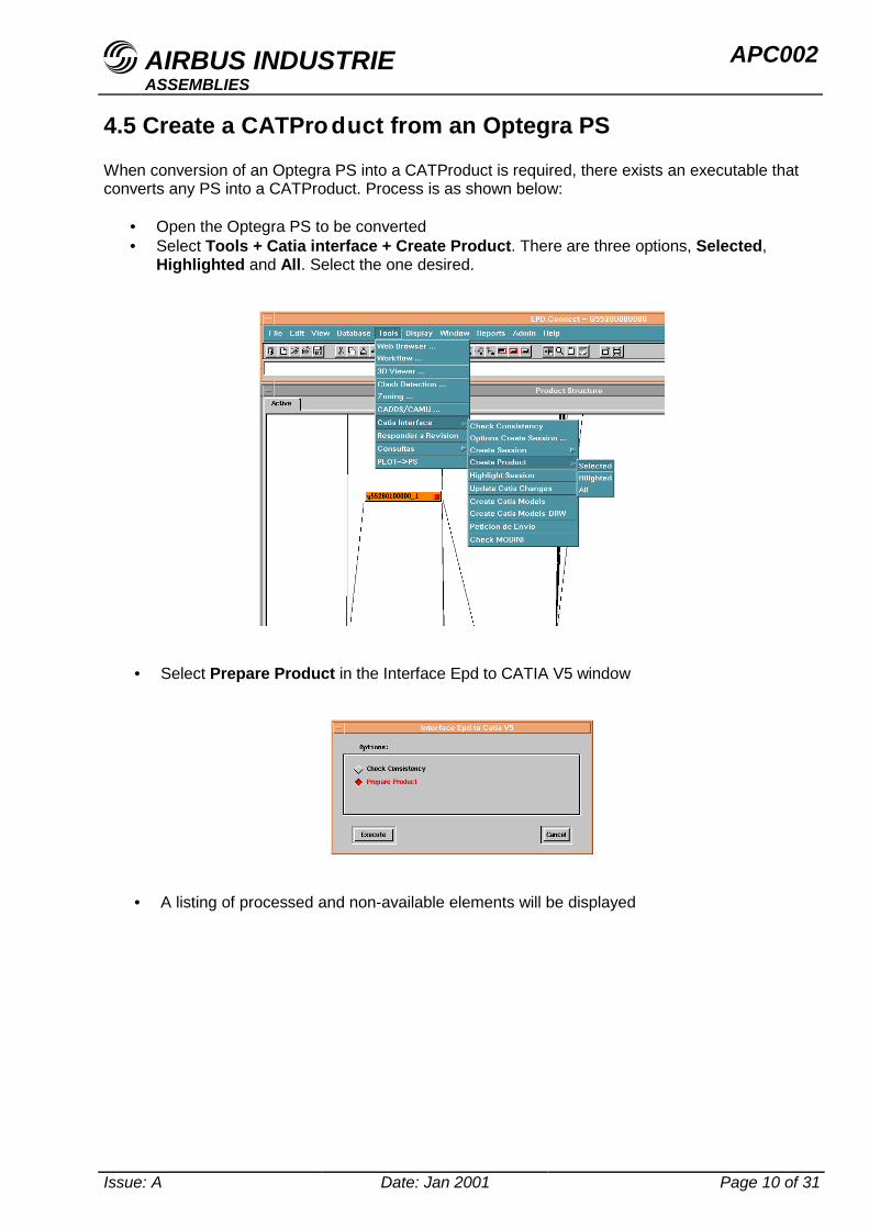
• Select Prepare Product in the Interface Epd to CATIA V5 window
• A listing of processed and non-available elements will be displayed

AIRBUS INDUSTRIE APC002ASSEMBLIES
Issue: A Date: Jan 2001 Page 11 of 31
• In Catia V5 select the icon Epd to Catia V5
• The user will be prompted for confirmation, click OK if right, otherwise click cancel andreview the selection performed
• Final result is as follows
Epd to Catia V5

AIRBUS INDUSTRIE APC002ASSEMBLIES
Issue: A Date: Jan 2001 Page 12 of 31
5 INSERTION OF C OMPONENTS
The component insertion process will basically be the same for all types of assemblies
• Signout the work assembly from the VAULT• Open the work assembly, in the write model, from the Modlocal• From the VAULT, oOpen the element to be inserted, CATProduct or CATPart in a different
window• Split the screen in two vertical or horizontal windows• Copy the element to be inserted and paste it into the wok assembly
Option Insert+Existing Component may be used sometimes if elements to be inserted areavailable in the Modlocal, because a Get or a Read of these elements has already been performed,but only in these two cases.
5.1 Single level asse mbly
A single level assembly includes parts only and no other sub-assemblies.
Below is the components insertion process in a single level assembly:

AIRBUS INDUSTRIE APC002ASSEMBLIES
Issue: A Date: Jan 2001 Page 13 of 31
• Sign out the assembly from the Vault, for this purpose, select the assembly first and thenthe Vault+Get Latest Rev option from the scroll down menu in the Vault tab from theData Browser window.
• Confirm the operation and verify that the process was correct and the element isassigned to the user and in the Modlocal
• Open the assembly from the Modlocal. In the Data Browser, select the assembly from theLocal tab, Select Custom+Open CatiaV5 option from the scroll down menu and confirm.
Select
ElementassignedCorrect process
Confirmation
Confirmación

AIRBUS INDUSTRIE APC002ASSEMBLIES
Issue: A Date: Jan 2001 Page 14 of 31
• Select the icon Load_Documents from the Catia V5 window to read the CATProductfrom the Modlocal
• Open the parts to be inserted from the Vault, following the same procedure for openingthe CATProduct
Select

AIRBUS INDUSTRIE APC002ASSEMBLIES
Issue: A Date: Jan 2001 Page 15 of 31
• Copy component from the part window and paste into the assembly. The component canalso be taken from the part window and dragged to the assembly window
Work assembly
Component to beinserted
Copy from thewindow ofcomponent to beinserted
Paste in the workassembly window Operation
outcome
AIRBUS INDUSTRIE APC002ASSEMBLIES
Issue: A Date: Jan 2001 Page 16 of 31
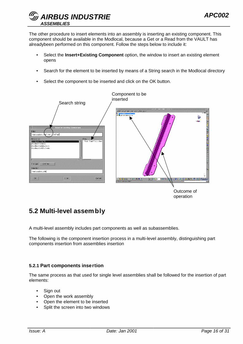
The other procedure to insert elements into an assembly is inserting an existing component. Thiscomponent should be available in the Modlocal, because a Get or a Read from the VAULT hasalreadybeen performed on this component. Follow the steps below to include it:
• Select the Insert+Existing Component option, the window to insert an existing elementopens
• Search for the element to be inserted by means of a String search in the Modlocal directory
• Select the component to be inserted and click on the OK button.
5.2 Multi-level assem bly
A multi-level assembly includes part components as well as subassemblies.
The following is the component insertion process in a multi-level assembly, distinguishing partcomponents insertion from assemblies insertion
5.2.1 Part components insertion
The same process as that used for single level assemblies shall be followed for the insertion of partelements:
• Sign out• Open the work assembly• Open the element to be inserted• Split the screen into two windows
Component to beinserted
Search string
Outcome ofoperation

AIRBUS INDUSTRIE APC002ASSEMBLIES
Issue: A Date: Jan 2001 Page 17 of 31
• Copy part component from its window and paste it in the work assembly
5.2.2 Subassemblies insert ion
Two types of subassemblies are distinguished when they are to be inserted, small assemblies andlarge assemblies. Small assemblies insertion shall be made by visualisation thereof and largeassemblies insertion shall be made without visualisation.
The following is the assembly insertion process without visualisation
• Open the work CATProduct without visualisation
To open a CATProduct without visualisation, Options is selected from the Tools menu. SelectProduct+Product Structure, from the window opening up and select option: Do not activatedefault shapes on open as shown in image below:
• Open the CATProduct to be included from the Vault, do it also without geometry visualisation• Copy the assembly to be included and paste it into the work assembly.
• Replace assembly in the Vault
Assembly to beincluded (withoutvisualisation)
Work assembly
Icon to be selected

AIRBUS INDUSTRIE APC002ASSEMBLIES
Issue: A Date: Jan 2001 Page 18 of 31
5.3 Assembly with V4 elements
Process to include V4 elements in an assembly shall be as follows:
• Sign out assembly in Vault• Open it from the Modlocal• Perform a Read Latest Rev on the V4 element to be included• Insert V4 element as an existing component from the Modlocal directory• Replace assembly in the Vault
Processes stated in above paragraphs shall be used to include V5 elements into the sameassembly, either for parts or subassemblies.
5.4 Assembly comm on to different departments
When it is necessary to create an assembly including subassemblies from different departments toperform a clash detection, or to perform different mock-up activities, the process stated in Multi-levelassembly shall be adhered to.

AIRBUS INDUSTRIE APC002ASSEMBLIES
Issue: A Date: Jan 2001 Page 19 of 31
6 COMPONENTS P OSITIONINGTBD

AIRBUS INDUSTRIE APC002ASSEMBLIES
Issue: A Date: Jan 2001 Page 20 of 31
7 STANDARD PAR TS
7.1 Insertion of stan dard parts
Follow steps below to incorporate standard parts into an assembly:
• Open assembly wherein standard parts are to be included
• Select the catalogue browser icon and pick work catalogue
• Select the desired standard part from the listing
• Deploy the options menu with the right mouse button and select option Copy
• On the assembly node select Paste
Standard part may be selected and dragged to the CATProduct node with the same result
• Position the standard part within the assembly
Catalogue
Catalogue browsericon

AIRBUS INDUSTRIE APC002ASSEMBLIES
Issue: A Date: Jan 2001 Page 21 of 31
7.2 Standard parts p ositioning
Standard parts positioning depends on supporting geometry on which they are to be located. Thefollowing classification has been established based on the support.
• Along a direction.• Supporting on flat surfaces.• Supported on surfaces
Positioning of repeated standard parts along a direction.
The following is the process to be followed:
• Locate the standard part in the tree in the traditional manner. It therefore stays in its 0,0,0position.
• Approach it to the support by means of the snap option, selecting any point in the standard partand any other point in the support.
• Position it in its final position using snap, constrains or compass.• Select option fast multinstantiation definition and the following window opens up:
• Select the standard part as element to instantiate.• Select the type of parameters desired to provide, the number of standard parts, spacing between
each other or total spacing between the first and the last ones in the parameters tab (two out ofthe three ones have to be selected).
• Enter the values of the selected parameters.• Enter direction in which parameters are located. It may be an edge, a flat surface, etc.

AIRBUS INDUSTRIE APC002ASSEMBLIES
Issue: A Date: Jan 2001 Page 22 of 31
Positioning of standard parts supported on flat surfaces.
Dealing with flat surfaces, there are two positioning alternatives, depending on whether patternsexist or not.
Process is as follows if there are preset patterns:
• Position the first standard part in the same manner as in the above paragraph (snap, constrainsor compass) located in the feature (hole) origin for the pattern. (It is assumed a pattern has beencreated for each different type of standard part).
First standardpart positioning
MultinstantiationDirection
Standard partspositionedaccording to adirection

AIRBUS INDUSTRIE APC002ASSEMBLIES
Issue: A Date: Jan 2001 Page 23 of 31
• Select the pattern usage icon and the following definition window opens up.
• Select the one corresponding to the standard part selected as pattern.• Select the standard part.• Select the reuse the original pattern option from the first instance on pattern flap.• Activate selected from the re-use constraints options.
• Finally, update results.

AIRBUS INDUSTRIE APC002ASSEMBLIES
Issue: A Date: Jan 2001 Page 24 of 31
Should there be no patterns, standard parts are positioned one by one using constraints, snap or thecompass
Standard parts positioning laying on surfaces.
First of all it is necessary to have the hole feature (in addition to the positioning point) created on thesupport in each location the standard part is to be positioned, in order to facilitate the process.
The following is the process to be followed:
• After the standard part to be positioned is located in the tree structure, it is approached to thesupport by means of the snap function, selecting one point in the standard part and another onein the support.
• Perform a multi-instantiation of as many repeated standard parts as necessary in any direction.• Move to the coincidence option and select the hole centre line and the standard part centre line
for each standard part and with the same option, select the standard part bearing surface andthe support point.
• Repeat the process for each standard part.
Note: If the surface was ruled, there is the possibility to use the multi- instantiation if standard partsare located along one of the rules of the surface.

AIRBUS INDUSTRIE APC002ASSEMBLIES
Issue: A Date: Jan 2001 Page 25 of 31
Methodology for standard parts positioning.
The table below states the methodology for standard parts positioning as a function of the type ofassembly and the support:
ALONG ONEDIRECTION
ON FLATSURFACES
RULEDSURFACES
DOUBLECURVATURESURFACES
STRUCTURESGeneral.Above 20 stdRivets NO PATTERN &
POINTSPOINTS-MULTINS
POINTS
Nut Plates NO PATTERN &POINTS
POINTS-MULTINS
POINTS
Nut-screw-washer
PATTERN &POINTS
POINTS-MULTINS
POINTS
Clamps-Supports
PATTERN &POINTS
POINTS-MULTINS
POINTS
Small. Lessthan 20 std
Rivets MULTI-INSTANTIATION PATTERN-CONSTRAINTS
CONSTRAINTS-MULTINS
CONSTRAINTS,ONE BY ONE
Nut Plates MULTI-INSTANTIATION PATTERN-CONSTRAINTS
CONSTRAINTS-MULTINS
CONSTRAINTS,ONE BY ONE
Nut-screw-washer
MULTI-INSTANTIATION PATTERN-CONSTRAINTS
CONSTRAINTS-MULTINS
CONSTRAINTS,ONE BY ONE
Clamps-Supports
MULTI-INSTANTIATION PATTERN-CONSTRAINTS
CONSTRAINTS-MULTINS
CONSTRAINTS,ONE BY ONE
HYDRAULICSYSTEMS
Supports forattachment tostructures
MULTI-INSTANTIATION PATTERN-CONSTRAINTS
CONSTRAINTS-MULTINS
CONSTRAINTS,ONE BY ONE
ELECTRICSYSTEMS
Supports forattachment tostructures
MULTI-INSTANTIATION PATTERN-CONSTRAINTS
CONSTRAINTS-MULTINS
CONSTRAINTS,ONE BY ONE
MECHANICSYSTEMS
Supports forattachment tostructures
MULTI-INSTANTIATION PATTERN-CONSTRAINTS
CONSTRAINTS-MULTINS
CONSTRAINTS,ONE BY ONE
AIRBUS INDUSTRIE APC002ASSEMBLIES
Issue: A Date: Jan 2001 Page 26 of 31
8 SYMMETRICAL ASSEMBLY
8.1 Symmetrical Par ts
8.2 Parts in symmet rical position

AIRBUS INDUSTRIE APC002ASSEMBLIES
Issue: A Date: Jan 2001 Page 27 of 31
9 BOM
10 MODIFICATIONS
11 TOLERANCES
12 INTERFERENCE S

AIRBUS INDUSTRIE APC002ASSEMBLIES
Issue: A Date: Jan 2001 Page 28 of 31
References

AIRBUS INDUSTRIE APC002ASSEMBLIES
Issue: A Date: Jan 2001 Page 29 of 31
Glossary
MDU User's Manual

AIRBUS INDUSTRIE APC002ASSEMBLIES
Issue: A Date: Jan 2001 Page 30 of 31
Approval and Authorisation
Approval Authorisation

AIRBUS INDUSTRIE APC002ASSEMBLIES
Issue: A Date: Jan 2001 Page 31 of 31
Issue records
Issue Date Summary and reason for modification
![Improving Collaboration with Cabin Suppliers€¦ · · 2014-09-25Stacking rules new interfaces new application Legend [505] ... CATIA V4, CATIA V5 Optegra PRIMES ... Airbus-BerndFeldvoss-](https://static.fdocuments.in/doc/165x107/5b011c987f8b9a0c028dc38e/improving-collaboration-with-cabin-2014-09-25stacking-rules-new-interfaces-new.jpg)