Eaton UltraShift® PLUS TRDR1110 EN-US
44
Driver Instructions December 2017 UltraShift ® PLUS Automated Transmission TRDR1110 EN-US UltraShift PLUS Linehaul Active Shifting (LAS) UltraShift PLUS Linehaul Small Step Efficiency (LSE) UltraShift PLUS Multipurpose Extreme Performance (MXP) UltraShift PLUS Multipurpose High Performance (MHP) UltraShift PLUS Vocational Active Shifting (VAS) UltraShift PLUS Vocational Construction Series (VCS) UltraShift PLUS Vocational High Performance (VHP) UltraShift PLUS Vocational Multipurpose Series (VMS) UltraShift PLUS Vocational Extreme Performance (VXP) UltraShift PLUS Passenger Vehicle (PV)
-
Upload
duongkhanh -
Category
Documents
-
view
236 -
download
0
Transcript of Eaton UltraShift® PLUS TRDR1110 EN-US

Driver Instructions
December 2017
UltraShift® PLUSAutomated TransmissionTRDR1110 EN-US
UltraShift PLUS Linehaul Active Shifting (LAS)UltraShift PLUS Linehaul Small Step Efficiency (LSE)UltraShift PLUS Multipurpose Extreme Performance (MXP)UltraShift PLUS Multipurpose High Performance (MHP)UltraShift PLUS Vocational Active Shifting (VAS)UltraShift PLUS Vocational Construction Series (VCS)UltraShift PLUS Vocational High Performance (VHP)UltraShift PLUS Vocational Multipurpose Series (VMS)UltraShift PLUS Vocational Extreme Performance (VXP)UltraShift PLUS Passenger Vehicle (PV)


Warnings and Cautions
!
!
!
Warnings and Cautions
Definitions
Warning: Indicates you will be Severely Injured or Killed if you do not follow the indicated procedure.
Caution: Indicates an Immediate Hazard, which could result in Severe Per-sonal Injury if you do not follow the indicated procedure.
Important: Indicates vehicle or property damage could occur if you do not fol-low the indicated procedure.
Note: Note indicates additional detail that will aid in the diagnosis or repair of a component or system.
WarningRead the entire driver instructions before operating this transmission.
Before starting a vehicle always be seated in the driver's seat, select “N” on the shift control, and set the parking brake.
If engine cranks in any gear other than neutral, service vehicle immediately.
Before working on a vehicle, parking the vehicle, or leaving the cab with the engine running, place the transmission in neutral, set the parking brakes, and block the wheels.
For safety reasons, always engage the service brakes prior to selecting gear positions from “N”.
Always ensure that fuel is at a sufficient operating level before operating vehicle. A loss of engine power could result in inhibited shifting.
!
i

Warnings and Cautions
CautionDo not release the parking brake or attempt to select a gear until the air pres-sure is at the correct level.
Before operating the PTO, refer to “Transmission Power Take Off Operation.”
Battery (+) and (-) must be disconnected prior to any type of welding on any UltraShift PLUS equipped vehicle.
ImportantIt is a requirement that the driver of a commercial vehicle specified under paragraph A sections 1-6 of FMCSA regulation 392.10 need only cross rail-road grade crossings in a gear that permits the vehicle to complete the cross-ing without a change of gears.
This can only be achieved by utilizing the MANUAL mode. Please refer to pages 7 and 8 for correct MANUAL mode operation.
!
!
ii

iii
Table of Contents
Warnings and Cautions . . . . . . . . . . . . . . . . . . . . . . . . . . . . . . . i
OperationShift Console Modes . . . . . . . . . . . . . . . . . . . . . . . . . . . . . . . . . . . . 1Gear Display . . . . . . . . . . . . . . . . . . . . . . . . . . . . . . . . . . . . . . . . . . . 2Start-up and Power Down . . . . . . . . . . . . . . . . . . . . . . . . . . . . . . . . 3Reverse Mode . . . . . . . . . . . . . . . . . . . . . . . . . . . . . . . . . . . . . . . . . 4Drive Mode . . . . . . . . . . . . . . . . . . . . . . . . . . . . . . . . . . . . . . . . . . . 6MANUAL Mode . . . . . . . . . . . . . . . . . . . . . . . . . . . . . . . . . . . . . . . . 7LOW Mode . . . . . . . . . . . . . . . . . . . . . . . . . . . . . . . . . . . . . . . . . . . . 9Transmission Shift Console Mode Configuration / Operation
Standard (Default) . . . . . . . . . . . . . . . . . . . . . . . . . . . . . . . . . . 10Urge to Move . . . . . . . . . . . . . . . . . . . . . . . . . . . . . . . . . . . . . . . 11Creep . . . . . . . . . . . . . . . . . . . . . . . . . . . . . . . . . . . . . . . . . . . . 12Blended Pedal . . . . . . . . . . . . . . . . . . . . . . . . . . . . . . . . . . . . . . 13Transmission Configuration Switch . . . . . . . . . . . . . . . . . . . . . 14
Transmission Power Take Off (PTO)Stationary PTO Operation . . . . . . . . . . . . . . . . . . . . . . . . . . . . . 17Mobile PTO Operation . . . . . . . . . . . . . . . . . . . . . . . . . . . . . . . . 18Split Shaft PTO (SSPTO) Operation . . . . . . . . . . . . . . . . . . . . . 18
Soft Soil Operation (Heavy-Duty Models Only) . . . . . . . . . . . . . . . . 19Sliding Trailer Axle . . . . . . . . . . . . . . . . . . . . . . . . . . . . . . . . . . . . . . 20Trailer Connecting . . . . . . . . . . . . . . . . . . . . . . . . . . . . . . . . . . . . . . 20Operation with Paving Machine . . . . . . . . . . . . . . . . . . . . . . . . . . . . 20Transfer Dump Application Power Down and Start-up . . . . . . . . . . 212-Speed Axle . . . . . . . . . . . . . . . . . . . . . . . . . . . . . . . . . . . . . . . . . . 23Features . . . . . . . . . . . . . . . . . . . . . . . . . . . . . . . . . . . . . . . . . . . . . . 24
Service & MaintenanceGeneral Model Information . . . . . . . . . . . . . . . . . . . . . . . . . . . . . . . . 29Troubleshooting . . . . . . . . . . . . . . . . . . . . . . . . . . . . . . . . . . . . . . . . 32Proper Clutch Lubrication . . . . . . . . . . . . . . . . . . . . . . . . . . . . . . . . . 34Proper Transmission Lubrication . . . . . . . . . . . . . . . . . . . . . . . . . . . 35Vehicle Towing . . . . . . . . . . . . . . . . . . . . . . . . . . . . . . . . . . . . . . . . . 38

1
Operation
Shift Console Modes
Note: The Transmission Shift Console Mode Configuration determines clutch operation during vehicle launch. (See page 10 for detailed information regarding clutch engagement options and operation instructions).
Warning: UltraShift PLUS initiates upshifts from MANUAL and LOW for engine over speed protection. Some engines do not use the engine overspeed protection.
R Selects Reverse (see page 4 for more details)
N Mode used for Start-up and Power-down
D Selects Drive (see page 6 for more details)
MANUAL Selects MANUAL (see page 7 for more details)
LOW Selects LOW (see page 9 for more details)
Service The service indicator alerts the driver of potential transmission problems.
Upshift / Downshift Buttons
Used in the MANUAL mode to select upshifts and downshifts and to change start gear, if available.
R - Reverse
N - Neutral
D - Drive
MANUAL
LOW
- Upshift
- Downshift
SERVICE
SHIFT
MANUAL
EATON FULLERTRANSMISSIONS
LOW
D
N
R
Button not used
Service Indicator
!

2
Operation
Gear Display
The Gear Display indicates the current gear position of the transmission. During an upshift or downshift the gear display may momentarily flash the tar-get gear position.
The “DASH” indicates the transmission may be torque locked in gear. See “Service and Maintenance Locked in Gear” section for more details.
“CA” will appear in the gear display if a clutch abuse event is occurring.
“AN” will appear in the gear display if the transmission goes into Auto Neutral.
In heavy-duty UltraShift™ PLUS Automated models, “GI” may briefly appear in the gear display after the engine is started. This indicates that the clutch release bearing will need to be greased soon. See “Optional Automated Lube Schedule” section for more information.
Note: “GI” stands for grease interval and may be misread as “G1” on gear dis-play.
Current Gear
Gear ShiftTransition Successful Gear
Shift
SolidMay Momentarily Flash
Solid

3
Operation
Start-up and Power Down
Start-up1. Turn the ignition key to “ON” and allow the UltraShift® PLUS to
power-up. • Engine cranking is delayed until the transmission power-up is
complete and the gear display shows a solid “N.”
2. Start the engine.3. Apply service brake.
• If the service brake is not applied while selecting a starting gear, the initial start gear will not be found and the driver will have to re-select Neutral and press the brake while re-selecting the desired mode.
4. Select the desired mode and starting gear on the shift console.
Note: The transmission will over-ride inappropriate start gear selections to avoid driveline damage.
5. Release the vehicle parking brakes.6. Release service brake and apply accelerator.
Note: The Transmission Shift Console Mode Configuration determines clutch operation during vehicle launch. (See page 10 for detailed information regarding clutch engagement options and operation instructions).
Power Down1. Select Neutral on the shift control.
• If gear display does not show solid “N,” neutral has not yet been obtained.
Note: Neutral should always be reached before the UltraShift PLUS power down is performed except in cases of emergency.
2. Set the vehicle parking brakes.3. Turn off the ignition key and allow the engine to shut down.

Operation
!
Reverse Mode• Selects default Reverse gear (see Note*).• Each time Reverse is selected from Neutral, the default Reverse gear
is engaged.• The vehicle will not engage Reverse above 2 mph.• On multi-speed auxiliary models, R1 to R2 and R3 to R4 shifts will
only be made by manually using up and downshift buttons while driving.
Note: The transmission cannot range shift while moving. Driver can split shift while moving if the vehicle is equipped with a multi-speed auxiliary sec-tion.
Note: R4 is only available on the UltraShift PLUS Multipurpose Extreme Per-formance (MXP) and UltraShift PLUS Vocational Extreme Performance (VXP) models.
Note: *If the driver attempt to select a non-neutral mode without depressing the service brakes the transmission will not shift into gear and transmis-sion will have to be returned to Neutral. Depress the brakes before selecting the desired mode again.
Important: Launching the vehicle in high range increases the likelihood of clutch abuse, and depending on the level of usage, could have a detrimental impact on clutch life.
4
Operation
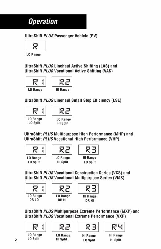
UltraShift PLUS Multipurpose High Performance (MHP) andUltraShift PLUS Vocational High Performance (VHP)
LO RangeLO Split
LO RangeHI Split
HI RangeLO Split
LO Range DR HI
LO Range DR LO
UltraShift PLUS Vocational Construction Series (VCS) andUltraShift PLUS Vocational Multipurpose Series (VMS)
HI RangeDR HI
LO RangeLO Range
UltraShift PLUS Multipurpose Extreme Performance (MXP) andUltraShift PLUS Vocational Extreme Performance (VXP)
HI Range HI Range
LO Range HI Split
LO Range LO Split
UltraShift PLUS Linehaul Small Step Efficiency (LSE)
UltraShift PLUS Linehaul Active Shifting (LAS) andUltraShift PLUS Vocational Active Shifting (VAS)
LO Range HI Range
UltraShift PLUS Passenger Vehicle (PV)
LO Range
5 HI SplitLO Split LO Split HI Split

6
Operation
Drive Mode• Automatically selects the start gear (see Note*). The selected start
gear will vary depending on several vehicle inputs like load, grade, and axle/transmission ratio. This start gear can be changed by using the up/down buttons, as long as the selection still falls into a gear that would allow the vehicle to launch without allowing the transmis-sion to obtain damage.
• If the start gear is changed using the up/down buttons, it will remain as the default until the vehicle is powered down or the selection is changed with the buttons again.
• Automatically performs all upshifts and downshifts in all gears except 1st (Only on the UltraShift PLUS Vocational Multipurpose Series (VMS) models) and Reverse on all models.
• A shift can be advanced by pressing the up/down buttons when the transmission is near the shift point.
• The transmission may also deny a shift while ascending or descend-ing grades if the load of the vehicle, and grade of the terrain in com-bination with the drivetrain ratio and engine torque will fall outside of the acceptable range to perform a shift. If the shift is denied it will sound a tone.
Note: Multiple gear upshifts and downshifts may be allowed when the shift buttons are pushed multiple times (Each button push equals one gear change request).
Important: Prior to ascending a steep grade the driver should reduce default start gear by one or ensure full throttle is applied for the duration of the grade so the vehicle maintains the proper engine and vehicle speed during the entire grade. Driver can button down by using the down arrow on the shift lever.
Note: *If the driver attempts to select a non-neutral mode without depressing the service brakes the transmission will not shift into gear and the driver will have to return to Neutral and depress the brakes before selecting the desired mode again.
Important: If the driver depresses and holds both pedals (even if done acci-dentally) the launch will be abrupt and the engine and brake forces may rock and bounce the vehicle. Releasing either pedal will stop this immediately.
!
!

Operation
MANUAL ModeMANUAL mode should be used whenever the driver wants to select the shifts instead of letting UltraShift select them automatically. For example, when the driver is moving around the yard, over railroad tracks, or on steep grades.
• Driver manually selects the start gear and uses the up/down buttons to shift (see Note *).
• System holds current gear unless otherwise prompted by using up / down-shift buttons, except for the “Transmission Override” condi-tions noted below.
Note: Multiple gear upshifts and downshifts may be allowed when the shift buttons are pushed multiple times (Each button push equals one gear change request).
Note: For optimal vehicle performance, it is recommended the vehicle be operated in “D” Drive mode.
MANUAL / Hold Mode
• The ability to restrict driver use of MANUAL mode is configurable. The default setting for this configuration is “Disabled” which allows standard MANUAL mode operation in all gears.
• When configured the MANUAL mode becomes a Hold gear function only (i.e. up/down buttons have no effect). In addition, provides an alert tone every 10 seconds.
• If the driver has selected MANUAL mode, and the transmission is in a gear equal to or greater than the configured Hold Gear; the trans-mission will remain in the current gear, up/down buttons are dis-abled (except for “Transmission Override” conditions).
• Gears lower than the configured hold gear will allow standard MAN-UAL mode operation.
7

Operation
!
!
Warning: UltraShift PLUS initiates upshifts from MANUAL and LOW for engine over speed protection. Some engines do not use the engine overspeed protection.
• The system will automatically shift or inhibit shifts to prevent over-speed or under-speed of the engine.
• The transmission may also deny a shift while ascending or descend-ing grades if the load of the vehicle, and grade of the terrain in com-bination with the drivetrain ratio and engine torque will fall outside of the acceptable range to perform a shift. If the shift is denied it will sound a tone.
Transmission Manual Override:
• If the vehicle is being back driven and the engine is approaching a higher than normal level, the transmission system will override the MANUAL position and perform and upshift.
• If the start gear is changed and it causes the engine to lug at takeoff, the transmission system will override the MANUAL position and select the best available gear.
Note: *If the driver attempts to select a non-neutral mode without depressing the service brakes the transmission will not shift into gear and the driver will have to return to Neutral and depress the brakes before selecting the desired mode again.
Important: If the driver depresses and holds both pedals (even if done acci-dentally) the launch will be abrupt and the engine and brake forces may rock and bounce the vehicle. Releasing either pedal will stop this immediately.
8

9
Operation
LOW ModeLOW mode should be used to maximize engine braking and minimize the use of the brake pedal. For example, when driving down long grades or when coming to a stop.
• Selects lowest available gear for start gear. (see Note *). The starting gear cannot be changed in LOW mode.
• If LOW is selected while moving, the transmission will not upshift (except for the Transmission Override conditions noted below). The transmission system will downshift at the earliest opportunity to pro-vide maximum engine braking.
Transmission LOW Override
• If the vehicle is being back driven and the engine is approaching a higher than normal level, the transmission system will override the MANUAL position and perform and upshift.
Warning: UltraShift PLUS initiates upshifts from MANUAL and LOW for engine over speed protection. Some engines do not use the engine overspeed protection.
Note: At higher engine speeds additional engine braking in LOW Mode could cause a loss of traction when on slippery surfaces.
Note: LOW is the only means to achieve the curbing gear or 1st on the UltraShift PLUS Vocational Multipurpose Series (VMS) mixer models.
Note: *If the driver attempts to select a non-neutral mode without depressing the service brakes the transmission will not shift into gear and the driver will have to return to Neutral and depress the brakes before selecting the desired mode again.
Important: If the driver depresses and holds both pedals (even if done acci-dentally) the launch will be abrupt and the engine and brake forces may rock and bounce the vehicle. Releasing either pedal will stop this immediately.
!
!

Operation
Transmission Shift Console Mode Configuration / OperationNote: Urge to Move and Blended Pedal should not be enabled with CNG
engines.
Note: The Blended Pedal clutch control feature is not available in Drive Mode.
The Transmission Shift Mode Configuration determines clutch operation when in Reverse/Drive/Manual/Low Mode.
These clutch control engagement options allow optimum mobility for the vehi-cle application. Each shifter mode can be independently configured to function with one of the clutch control features below. The default clutch engagement configuration in all modes is set at Standard from the factory, but can be changed using Eaton ServiceRanger.
Standard (Default)• Standard allows the driver full control of clutch engagement and the
clutch will open as the accelerator is released, the service brake is applied and the vehicle comes to a stop.
- When a gear is engaged; the clutch remains open until the driver releases the service brake and applies the accelerator.
- The clutch will open as the accelerator is released, the service brake is applied and the vehicle comes to a stop.
- A more aggressive clutch engagement is used in standard mode.
Launching:
1. Engage the desired gear.
2. Release service brake.
3. Apply accelerator.
Stopping:
1. Release the accelerator.
2. Apply service brake.
10

Operation
Urge to Move• Urge to Move allows the vehicle to automatically start moving when
the transmission is in gear and the driver releases the service brake. After the vehicle has launched the vehicle will creep at a constant speed at engine idle without the need to hold the throttle pedal posi-tion. The configuration is useful for stop and go applications allowing the vehicle to launch and creep without applying the accelerator.
• The vehicle speed is determined by the selected gear ratio operating at governed low engine idle speed. Any available start gear may be selected. However, the transmission will downshift or exit Creep if the engine lugs 150 rpm below the governed low engine idle speed due to load conditions.
- When a gear is engaged and the driver releases the service brake; the clutch will close automatically providing vehicle movement.
- The clutch will remain closed; allowing the vehicle to creep at constant engine idle after the service brake is released.
- The clutch will also open if the engine lugs 150 rpm below the governed low engine idle speed.
Launching:
1. Engage the desired gear.2. Release service brake (vehicle will automatically launch and creep at
constant engine idle).• Upshifts and Downshifts can be made while at constant engine
idle by pushing the Upshift / Downshift buttons. The transmis-sion may deny a shift and sound a tone if the load of the vehicle or grade of the terrain falls outside the acceptable range to per-form a shift.
3. Apply accelerator to accelerate the vehicle above idle.Stopping:
1. Release the accelerator (vehicle will creep at constant engine idle).• Upshifts and Downshifts can be made while at constant engine
idle by pushing the Upshift / Downshift buttons.2. Apply service brake.
11

Operation
Creep• Creep allows the vehicle to be driven at a constant speed at engine
idle without the need to hold the throttle pedal position. The configu-ration is useful for slow speed applications where steady vehicle speed is required (e.g. dump / spreader applications).
• The vehicle speed is determined by the selected gear ratio operating at governed low engine idle speed. Any available gear may be selected. However, the transmission will downshift or exit Creep if the engine lugs 150 rpm below the governed low engine idle speed due to load conditions.
- When a gear is engaged; the clutch remains open until the driver releases the service brake and applies the accelerator.
- The clutch will close and remain closed after the accelerator is released, allowing the vehicle to creep at constant engine idle.
- The clutch will also open if the engine lugs 150 rpm below the governed low engine idle speed due to load conditions.
Launching:
1. Engage the desired gear.
2. Release service brake.
3. Apply the throttle pedal to accelerate the vehicle until the clutch is closed (engaged).
4. Release the throttle pedal (vehicle will creep at constant engine idle).
• Upshifts and Downshifts can be made while at constant engine idle by pushing the Upshift / Downshift buttons. The transmis-sion may deny a shift and sound a tone if the load of the vehicle or grade of the terrain falls outside the acceptable range to per-form a shift.
5. Apply accelerator to accelerate the vehicle above idle.
12

Operation
Stopping:
1. Release the accelerator (vehicle will creep at constant engine idle).
• Upshifts and Downshifts can be made while at constant engine idle by pushing the Upshift / Downshift buttons.
2. Apply service brake.
Blended Pedal• Blended Pedal allows the driver to directly control the clutch engage-
ment through accelerator positioning. Initial accelerator pedal travel provides direct control of clutch engagement with engine held at idle; considerable accelerator pedal travel will transition to normal closed clutch engine throttle operation. The configuration is useful for very slow speed applications where a specific vehicle speed is required.
• The vehicle speed is determined by the accelerator positioning and selected gear ratio. Any available gear may be selected. However, the prolonged use of Blended Pedal in too high of a gear could increase the likelihood of clutch abuse.
Note: If the automated clutch does start to overheat, the display will show “CA” along with a warning tone. Full clutch actuation must be com-pleted quickly. If the abuse continues, the system will open the clutch and take away throttle control for a short period of time to allow the clutch to cool down.
- When a gear is engaged; the clutch remains open until the driver releases the service brake and applies the accelerator.
- Initial accelerator pedal travel provides direct control of clutch engagement with engine held at idle; considerable accelerator pedal travel will transition to normal closed clutch engine throt-tle operation.
- The clutch will open as the accelerator is released.
- The service brake can be used on grades to assist in keeping the vehicle from rolling back.
13

Operation
Launching:
1. Engage the desired gear.
2. Release service brake.
3. Apply the amount of throttle pedal needed to accelerate the vehicle to the desired speed or desired distance.
4. Apply full accelerator to accelerate the vehicle above idle.
Stopping:1. Release the accelerator.
2. Apply service brake.
Transmission Configuration Switch
The vehicle may be equipped with a Transmission Configuration switch. There are a variety of available Transmission Configuration switches depending on your vehicle make and model.
The Transmission Configuration Switch allows the vehicle to be tailor to match specific operation needs. Once configured the driver has the ability to switch between the preconfigured Primary and Secondary set of transmission configurations when desired. Example on next page.
14

Operation
Transmission Configuration Switch OperationThe Transmission Configuration switch should be used whenever the driver wants to select the secondary configurations. To select the secondary configuration settings, perform the following steps:
Eaton Cobra Lever:
1. Select Secondary Configuration Settings
• Press and hold the Upshift button for 4 seconds.
Note: The gear display will display “C2” on the gear display every 15 seconds indicating the transmission is using the Secondary Configuration settings.
Transmission Model FO(M)-XXE310C-LAS
Configuration Name Primary Configuration Value
Secondary Configuration Value
Default Start Gear 2 2
Maximum Start Gear 3 2
Coast Down Gear 5 5
Default Reverse Gear R1 R1
Maximum Reverse Gear
R2 R1
Reverse Configuration Standard Blended Pedal
Drive Configuration Standard Urge to Move
Manual Configuration Creep Blended Pedal
Low Configuration Standard Blended Pedal
Shift Point Calibration Economy Performance
Vocational Shift Response
Economy Fast
15

Operation
2. Re-select Primary Configuration Settings
• Press and hold the Downshift button for 4 seconds.
Note: The gear display will display “C1” on the gear display for 3 seconds indi-cating the transmission Primary Configuration settings have been reselected.
Eaton Push Button
Note: Not all Eaton Push Button controllers have Configuration Switch capa-bility.
1. Select Secondary Configuration Settings
• Press and release the Configuration button on the Eaton Push Button controller.
Note: The gear display will display “C2” on the gear display every 15 seconds indicating the transmission is using the Secondary Configuration settings.
2. Re-select Primary Configuration Settings
• Press and release the Configuration button on the Eaton Push Button controller.
Note: The gear display will display “C1” on the gear display for 3 seconds indi-cating the transmission Primary Configuration settings have been reselected.
OEM Switch
Note: Not all vehicles have an OEM momentary Configuration Switch. There may be a number of different OEM installed momentary Configuration Switches depending on your vehicle make and model. Contact your vehi-cle manufacturer for specific details.
16

Operation
Transmission Power Take Off (PTO)UltraShift PLUS Multipurpose High Performance (MHP), Multipurpose Extreme Performance (MXP), Vocational High Performance (VHP), Voca-tional Extreme Performance (VXP), Vocational Construction Series (VCS), Vocational Multipurpose Series (VMS), Linehaul Small Step Efficiency (LSE), Vocational Active Shifting (VAS) and Linehaul Active Shifting (LAS)
The ability to prevent a mode selection while the PTO is active is desired for certain vocational applications such as a vehicle with a boom.
A PTO configuration is available that allows or prevents a non-neutral mode selection when a PTO is active. The default setting for this configuration is “Disabled” which allows non-neutral mode selection and mobile operation when the PTO is active. When set to “Enabled” and the PTO is active, non-neu-tral mode selections and mobile operation is not allowed.
Stationary PTO OperationThe transmission countershaft PTO is used in this application.To engage the PTO for stationary operation, perform the following steps:
1. Apply the parking brake.2. Depress the service brake.3. Select “D” on the Shift Control. (This stops countershaft rotation for
PTO engagement.)4. Select the transmission PTO switch.5. Select “N” on the Shift Control.6. Release the service brake to engage the clutch and the PTO.7. Raise engine speed as required to operate PTO.
Note: To disengage the PTO, deselect the transmission PTO switch.
17

Operation
Mobile PTO Operation
The transmission countershaft PTO is used in this application and provides limited mobile operation in the start gears. To engage the PTO for mobile operation, perform the following steps:
1. Depress the service brake.2. Release the parking brake.3. Select “D” on the Shift Control. (This stops countershaft rotation for
PTO engagement.)4. Select the transmission PTO switch.5. Select “D,” MANUAL, “Neutral,” or “Reverse,” as required for vehicle
movement.6. Release the service brake to engage the clutch and the PTO.7. Raise engine speed as required to operate PTO.
Note: To disengage the PTO, deselect the transmission PTO switch.
Split Shaft PTO (SSPTO) Operation
To engage the split shaft PTO for stationary operation, perform the following steps:
1. Apply the parking brake.2. Select “N” on the Shift Control.3. Depress the service brake.4. Select the SSPTO switch. The SSPTO switch lamp should turn on.5. Verify SSPTO switch lamp is on and SSPTO is engaged.6. Select MANUAL and upshift/downshift buttons to select desired gear.
(Default gear ratio is 1:1.) The gear display will flash the SSPTO gear.7. Release the service brake and apply accelerator until gear display
stops flashing. (This indicates the clutch is engaged.)8. Use cruise control, accelerator, or remote throttle to reach desired
SSPTO speed.
Note: To disengage the SSPTO, deselect the SSPTO switch, deselect MANUAL, release parking brake, or apply service brake. (Engine will return to idle, clutch will disengage, and transmission will shift to Auto Neutral.)
18

Operation
Note: If the vehicle is equipped with remote Upshift/Downshift Buttons, the transmission can be remotely shifted after the SSSPTO engagement pro-cedure is completed. However the SSPTO may come to a stop while the transmission is completing the shift.
Note: If the vehicle is equipped with a remote clutch control, the vehicle throt-tle pedal cannot be used for transmission clutch engagement in SSPTO mode, the remote clutch control must be used to engage the clutch.
Soft Soil Operation (Heavy-Duty Models Only)• The transmission system requires the ATC option to be enabled
when driving in soft soil/sand or snow/ice to prevent wheel slippage and shifting issues. The ATC system has two modes, which are the normal on mode for sand and loose road surface and the mud/snow setting.
Normal Mode (Sand/Soft soil)
• The normal ATC option will engage the brakes on the wheel or side that the wheel slip is occurring to help the vehicle regain traction. The point at which the traction control will actuate the braking sys-tem increases with throttle. Low throttle allows the system to brake the wheels earlier and heavy/full throttle raises the point of the acceptable wheel slip.
• If using Drive mode in soft soil/sand - Maintain the engine RPM between 1000-1300 RPM to prevent unnecessary upshifting.
• If using MANUAL mode in soft soil/sand - Do not attempt an up-shift and try to maintain the current gear.
• If the vehicle comes to a stop in the sand it may be necessary to back up prior to attempting forward movement.
Mud/Snow/Ice Mode
• The mud/snow/ice ATC option can be selected by depressing the ATC switch until the ATC lamp flashes. This mode raises the wheel slip speed that is allowed before the traction control activates. The point at which the traction control will actuate the braking system increases with throttle. Low throttle allows the system to brake the wheels earlier and heavy/full throttle raises the point of the accept-able wheel slip.
19

Operation
Snow/Ice Operation
• The UltraShift PLUS transmission is designed to work in coordina-tion with the ATC system to ensure optimal operation. However, if the driver observes low friction road conditions (snow, rain, ice, etc.) and does not want the transmission to shift, risking wheel slippage, the driver should select MANUAL mode. MANUAL mode holds the current gear position under most operating conditions-the transmis-sion will only shift when the driver uses the upshift/downshift but-tons. Once road conditions improve, the driver should revert back to Drive mode.
Sliding Trailer Axle• Ensure axle rails and locks are properly maintained.• Follow proper procedure for unlocking and sliding the trailer axles.• Use Low mode (1st gear) for forward direction and Reverse (R1) for
reverse direction.• Avoid repeat attempts if the sliding axle is not moving.
Note: If repeat attempts are made and the automated clutch starts to overheat, the display will indicate “CA” along with a warning tone.
Trailer Connecting• Prior to backing under the trailer, ensure proper trailer height.
• Use Low mode (1st gear) for forward direction and Reverse (R1) for reverse direction.
Operation with Paving Machine1. Back the vehicle to the paver.
2. Move the shift lever to neutral. (“N” should appear in gear display.)
3. Allow the paver to move the truck forward.
4. When ready to pull away from the paving machine, the driver can select “D” (if the vehicle is being pushed at or above 1 mph). The engine will synchronize and put the UltraShift PLUS into the appro-priate gear, allowing the vehicle to pull away from the paver.
20
Operation
!
!
!
!
!
!
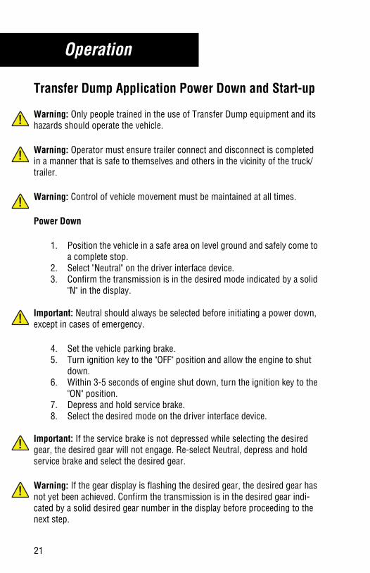
Transfer Dump Application Power Down and Start-up
Warning: Only people trained in the use of Transfer Dump equipment and its hazards should operate the vehicle.
Warning: Operator must ensure trailer connect and disconnect is completed in a manner that is safe to themselves and others in the vicinity of the truck/trailer.
Warning: Control of vehicle movement must be maintained at all times.
Power Down
1. Position the vehicle in a safe area on level ground and safely come to a complete stop.
2. Select "Neutral" on the driver interface device.3. Confirm the transmission is in the desired mode indicated by a solid
"N" in the display.
Important: Neutral should always be selected before initiating a power down, except in cases of emergency.
4. Set the vehicle parking brake.5. Turn ignition key to the "OFF" position and allow the engine to shut
down.6. Within 3-5 seconds of engine shut down, turn the ignition key to the
"ON" position.7. Depress and hold service brake.8. Select the desired mode on the driver interface device.
Important: If the service brake is not depressed while selecting the desired gear, the desired gear will not engage. Re-select Neutral, depress and hold service brake and select the desired gear.
Warning: If the gear display is flashing the desired gear, the desired gear has not yet been achieved. Confirm the transmission is in the desired gear indi-cated by a solid desired gear number in the display before proceeding to the next step.
21
Operation
!
!
!
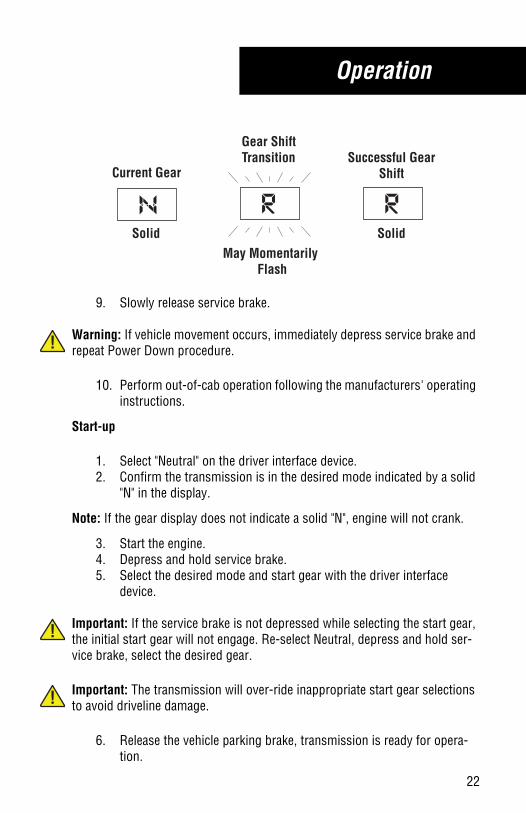
9. Slowly release service brake.
Warning: If vehicle movement occurs, immediately depress service brake and repeat Power Down procedure.
10. Perform out-of-cab operation following the manufacturers' operating instructions.
Start-up
1. Select "Neutral" on the driver interface device.2. Confirm the transmission is in the desired mode indicated by a solid
"N" in the display.
Note: If the gear display does not indicate a solid "N", engine will not crank.
3. Start the engine.4. Depress and hold service brake.5. Select the desired mode and start gear with the driver interface
device.
Important: If the service brake is not depressed while selecting the start gear, the initial start gear will not engage. Re-select Neutral, depress and hold ser-vice brake, select the desired gear.
Important: The transmission will over-ride inappropriate start gear selections to avoid driveline damage.
6. Release the vehicle parking brake, transmission is ready for opera-tion.
Current Gear
Gear ShiftTransition Successful Gear
Shift
SolidMay Momentarily Flash
Solid
22

Operation
!
!
2-Speed Axle
If equipped, a 2-speed axle allows the vehicle operator to select a lower axle ratio for improved performance when launching from a stop with a heavy load.
Warning: Do not shift the 2-speed axle when the vehicle is on a grade.
Important: If the 2-speed axle "Low" setting is selected, ensure "MANUAL" mode is selected and use the "Upshift" and "Downshift" buttons on the driver interface device to shift the transmission.
23

Operation
Features
Hill Start Aid Operation (HSA)
Hill Start Aid defaults to the “On” position. In heavy-duty UltraShift PLUS models, it can be turned “Off” by pressing and releasing the Hill Start Aid switch, however, it will turn back on after the first successful launch. If the switch is turned off, the lamp in the Hill Start switch will flash. (Medium-duty UltraShift PLUS models do not have a HSA override switch.)
The grade at which Hill Start Aid is active is defaulted to 1% but can be config-ured to activate on a 2% or 3% grade
A grade sensor is used to determine when to engage Hill Start Aide. The driver can view the grade reading in the Gear Display by the following process:
• Ignition is on with engine not running.• Shift Device is set to Neutral.• Depress the Accelerator Pedal (5) times within 10 seconds.• The grade will be displayed in 1% increments with Up or Down
arrows indicating slope direction.
Vehicle Facing Uphill - Forward Mode
• Vehicle must be on incline greater than 1% and in a forward mode.• Bring vehicle to a stop and depress the service brakes then release
the service brakes.
Note: Vehicle will begin to move after 3 seconds, and the clutch will perform partial engagements to slow the vehicle motion. Driver must either step on the brake or apply the throttle.
24

Operation
!
Vehicle Facing Downhill - Reverse Mode
• Vehicle must be on a decline greater than 1% and in Reverse mode.• Bring vehicle to a stop and depress the service brakes then release
the service brakes.
Note: Vehicle will begin to move after 3 seconds, and the clutch will perform partial engagements to slow the vehicle motion. Driver must either step on the brake or apply the throttle.
Clutch Abuse Protection• This vehicle uses an automated clutch for launching the vehicle;
however the clutch can still overheat and slip with improper use.• DO select the lowest possible start gear for the application. If moving
slowly is require, select 1st or R1.• DO use Creep mode when appropriate.• DO use the Service Brakes and let Hill Start Aid assist when launch-
ing on an incline.• DO minimize the time it takes to engage the clutch from rest.• Do NOT use the throttle to hold the vehicle on an incline. (Use Ser-
vice Brakes).• Do NOT use the throttle to stop roll back on an incline after Hill Start
Aid disengages. (Use Service Brakes and then relaunch).• Do NOT continually start and stop, especially when loaded (use a
lower gear or Creep mode).• If the automated clutch does start to overheat, the display will show
“CA” along with a warning tone. Full clutch actuation must be com-pleted quickly. If the abuse continues, the system will open the clutchand take away throttle control for a short period of time to allow theclutch to cool down.
Engine Over-Speed Protection• The transmission system will upshift if necessary to prevent engine
over-speed in Drive, MANUAL and LOW modes.
Warning: UltraShift PLUS initiates upshifts from MANUAL and LOW for engine overspeed protection. Some engines do not use the engine overspeed protection.
25

Operation
Shuttle Shifting• Shuttle shifting from Reverse to any forward mode is only allowed if
the vehicle speed is approximately zero.
Auto Start Gear Selection• The transmission system uses various inputs to automatically select
the best start gear in Drive and MANUAL.• This selection can be changed using the up/down buttons, however,
if the selection requested could cause damage or engine lugging the request will be denied and an audible tone will sound.
Skip Shifting• When appropriate, the transmission system may skip shift in Drive
mode.• Skip shifts can be performed in MANUAL by pressing the up/down
buttons providing the current conditions like load and grade allow this condition.
Note: Multiple gear upshifts and downshifts may be allowed when the shift buttons are pushed multiple times. (Each button push equals one gear change request.)
Auto Neutral • The transmission system will automatically shift to neutral if the
vehicle is left in Drive and the parking brakes are set.• “AN” will appear in the gear display. Driver must select Neutral and
then select the desired forward or reverse mode with the service brake applied.
Remote Throttle (Heavy-Duty Models Only)• The Parking Brake must be set and the shift lever must be in Neutral
for Remote Throttle to function. Remote Throttle will not function in Auto Neutral.
26

Operation
Load Based Shifting• The transmission system will adapt to the conditions of the vehicle to
change the shift points based on the followings inputs:• Vehicle grade• Engine RPM• Throttle position• Vehicle load
• After changing loads or powering up the transmission system needs to relearn these inputs for the first few shifts to make the proper adjustments.
Coast Mode• When coasting to a stop on level terrain the transmission system
may not downshift into the lower gears. It will select a gear after the throttle is reapplied.
Cruise Control• This transmission system is compatible with cruise control.
Neutral Coast ModeIf equipped and enabled, Neutral Coast Mode allows the transmission to dis-engage the driveline by pulling out of gear on slight downhill grades, where little to no engine power is required, when the vehicle is in cruise control and the transmission is in Drive Mode.
• When Neutral Coast Mode is active, the engine will drop to idle speed and the transmission will disengage.
• The gear display may flash a gear number or indicate Neutral when Neutral Coast Mode is active, depending upon specific OEM imple-mentation.
• If a flashing number is indicated in the gear display, this represents the gear that the transmission will select when it is necessary to engage a gear.
27

Operation
• The transmission will exit Neutral Coast Mode and reengage an appropriate gear under any of the following conditions:
- Vehicle brakes are applied
- Driver depresses accelerator pedal
- Cruise control is canceled
- A mode other than Drive is selected
- Cruise high or low set speeds are exceeded
- Maximum vehicle grade is exceeded
- Request by an adaptive cruise system
• Various brand names may be used for Neutral Coast systems.
Automated Lube Schedule• The heavy-duty UltraShift PLUS has an optional prognostic feature
that notifies the operator when the Clutch Release Bearing needs greasing.
• At the appropriate grease interval and shortly after each engine start, “GI” will momentarily appear in the gear display, along with an audi-ble tone. This will continue to occur at each engine start until clutch service has been completed.
• The operator can choose to follow this Automated Lube Schedule or the published lube guidelines in the Lubrication Manual TCMT0021.
Note: “GI” stands for grease interval and may be misread as “G1” on gear dis-play.
28

Service & Maintenance
General Model Information
NomenclatureUltraShift PLUS Linehaul Transmissions
UltraShift PLUS Performance Transmissions
F
Brand - Fuller Overdrive
X 100 + 50 Nominal Torque Lb. Ft.
Configuration
Linehaul ActiveShifting
Ratio Set
Number of Speeds
Design Level Mechicanical & Electronic
O (M)
Multi-torque
X X E 3 10 C L A S
F
Brand - Fuller Overdrive
X 100 + 50 Nominal Torque Lb. Ft.
Configuration
Linehaul SmallStep Efficiency
Ratio Set
Number of Speeds
Design Level Mechicanical & Electronic
O (M)
Multi-torque
X X E 3 10 C L S E
F
Brand - Fuller Overdrive
O -
X 100 + 50 Nominal Torque Lb. Ft.
Configuration
Multipurpose
Ratio Set
Number of Speeds
X X E 3 1 3 A - M H P
High Performance
Design Level Mechicanical & Electronic
F
Brand - Fuller Overdrive
O -
X 100 + 50 Nominal Torque Lb. Ft.
Configuration
Multipurpose
Ratio Set
Number of Speeds
X X E 3 1 8 B - M X P
Extreme Performance
Design Level Mechicanical & Electronic
29

Service & Maintenance
UltraShift PLUS Vocational Transmissions
F
Brand - Fuller Overdrive
O -
X 100 + 50 Nominal Torque Lb. Ft.
Configuration
Vocational
Ratio Set
Number of Speeds
X X E 3 1 8 B - V X P
Extreme Performance
Design Level Mechicanical & Electronic
F
Brand - Fuller Overdrive
O -
X 100 + 50 Nominal Torque Lb. Ft.
Configuration
Vocational
Ratio Set
Number of Speeds
X X E 3 0 8 L L - V C SConstruction Series
Design Level Mechicanical & Electronic
F
Brand - Fuller Overdrive
O -
X 100 + 50 Nominal Torque Lb. Ft.
Configuration
Vocational
Ratio Set
Number of Speeds
X X E 3 0 9 A L L - V M SMultipurposeSeries
Design Level Mechicanical & Electronic
F
Brand - Fuller Overdrive
X 100 + 50 Nominal Torque Lb. Ft.
Configuration
Ratio Set
Number of Speeds
Design Level Mechicanical & Electronic
O (M)
Multi-torque
X X E 3 10 C
Vocational
- V A S
Active Shifting
F
Brand - Fuller Overdrive
O -
X 100 + 50 Nominal Torque Lb. Ft.
Configuration
Vocational
Ratio Set
Number of Speeds
X X E 3 1 3 A - V H P
High Performance
Design Level Mechicanical & Electronic
30

Service & Maintenance
UltraShift PLUS Passenger Transmissions
Tag LocationThe blank spaces provided below are for recording transmission identification data and part numbers of maintenance items. All UltraShift PLUS transmis-sions are identified by the model and serial number. This information is stamped on the transmission identification tag and affixed to the case.
DO NOT REMOVE OR DESTROY THE TRANSMISSION IDENTIFICATION TAG.
The blank spaces provided below are for recording transmission identification
data. Have these reference numbers handy when ordering replacement parts
or requesting service information:
Transmission Model ________________________________
Transmission Serial Number _______________________________
E
Brand - Eaton Overdrive
O -
X 100 + 50 Nominal Torque Lb. Ft.
Configuration
Ratio Set
Number of Speeds
X X E 4 0 6 B P VPassenger Vehicle
Design Level Mechicanical & Electronic
--
31

Service & Maintenance
!
TroubleshootingDiagnostics
In the event there is a problem with a UltraShift PLUS model transmission, there are three primary tasks the driver should perform:
1. Note the driving condition under which the problem occurred.2. Note the condition of the transmission under which the problem
occurred (i.e. operation mode (Drive, MANUAL, LOW), current gear, engine speed, etc).
3. Reset system.
“F” in Gear Display and/or Vehicle Performance Issue
In the event there is an “F” in the gear display with no change in vehicle per-formance, continue to drive the vehicle.
In the event there is an “F” in the gear display and/or a change in the vehicle performance:
1. Continue to drive the vehicle to a safe location before selecting “N” NEUTRAL.
Important: Once “N” NEUTRAL is selected, a gear engagement may not be allowed.
2. When it is safe to do so, stop the vehicle.3. Place the transmission shift lever in “N” NEUTRAL and turn the igni-
tion key to the Off position.4. Wait at least 2 minutes.5. Restart the engine.6. If the problem continues and the vehicle is inoperable, contact a
service facility to have the vehicle and transmission system evaluated.
32

Service & Maintenance
Product Diagnostic Mode “PD”
In the event the transmission is put in Product Diagnostic mode, a “PD” will be displayed on the gear display, and the truck will not start. Use the follow-ing procedure to exit Product Diagnostic mode:
1. Select Neutral “N” and turn the key off.2. Wait at least 2 minutes.3. Turn the key on and power the system up.4. Verify there is an “N” on the gear display.5. Start the engine.
Locked in Gear
If the truck is shut down or stalls in gear, the UltraShift PLUS model transmis-sion may become locked in gear. The transmission will attempt to get to Neu-tral during the next power up if the shifter is in Neutral. If Neutral is achieved, a solid “N” appears on the Gear Display. If Neutral can not be achieved, a “DASH” will appear on the display and the engine will not start. If a dash appears during power up and the lever is in Neutral try the following:
1. Select Neutral, “N.” Turn the key OFF and let the transmission powerdown for at least 2 minutes.
2. Depress the brake pedal.3. Release the parking brake.4. Select Neutral.5. Turn the key to the ON position.6. The transmission will attempt to shift into Neutral once the key is
turned to the ON position, Driver may have to slightly release thebrake pedal to help let the torque off the drive line.
7. Once it reaches Neutral a solid “N” will appear on the Gear Displayand the truck will start. If a dash still appears after this proceduretake the vehicle to a local service center.
33

Service & Maintenance
!
Proper Clutch Lubrication
Heavy-Duty UltraShift PLUS ECA Clutch GreasingGuidelinesService Intervals
• Linehaul - 50,000 miles (80,000 Km) or 3 months• Vocational - 250 hours or 1 month
Important: It is highly important to follow proper ECA Clutch lube intervals. Failure to do so may result in clutch failure and unnecessary repairs.
The heavy-duty ECA clutch housing has two grease fittings on the lower right side. The upper port is marked “CS” for the upper Cross Shaft Assembly, while the lower port is marked “RB” for the Release Bearing.
For more detailed Cross Shaft greasing information, refer to the Release Yoke and Cross Shaft(s) Installation section in the Automated Transmission Service Manual TRSM0940. Refer to Clutch Service Manual CLSM0200 for release bearing greasing information.
Medium-Duty UltraShift PLUS ECA Clutch GreasingGuidelines
The medium-duty ECA clutch is maintenance free and does not require greas-ing. The medium-duty clutch housing has one grease fitting and it is the lubri-cation point for the Cross Shaft.
Cross Shaft Service Interval• At every chassis lubrication
34

Service & Maintenance
!
Proper Transmission Lubrication
Proper lubrication procedures are key to a good all-around maintenance pro-gram. If the lubricant is not doing its job or if the lubricant level is ignored, all the maintenance procedures in the world are not going to keep the transmis-sion running or assure long transmission life.
UltraShift PLUS Transmissions are designed so the internal parts operate in an oil bath circulated by the motion of the gears and shafts.
Thus, all parts are amply lubricated if these procedures are closely followed:
1. Maintain lubricant level and inspect regularly.2. Follow maintenance interval chart.3. Use the correct grade and type of lubricant.4. Buy lubricant from an approved dealer.
Mixing of Oil Types
Caution: Never mix engine oils & gear oils in the same transmission.
Engine oils and gear oils may not be compatible; mixing can cause breakdown of the lubricant and affect component performance. When switching between types of lubricants, all areas of each affected component must be thoroughly flushed.
Note: For a list of Eaton Approved Synthetic Lubricants, see TCMT0021 or call 1-800-826-HELP (4357).
Note: Additives and friction modifiers must not be introduced.
35

Service & Maintenance
Proper Transmission Lubrication LevelMake sure the transmission lubricant is level with the bottom of the fill open-ing. Being able to reach the lubricant with your finger does not mean the lubri-cant is at the proper level.
If the transmission operating angle is more than 12°, improper lubrication can occur. The operating angle is the transmission mounting angle in the chassis plus the grade (expressed in degrees).
Any time the transmission operating angle of 12° is exceeded for an extended period of time, the transmission must be equipped with an oil pump or cooler kit to insure proper lubrication.
Improper Oil Level
Hole
Proper Oil Level
Hole
36

Service & Maintenance
To check the oil level with the sight glass (Heavy-DutyModels Only)
1. Vehicle engine must be stopped and parked on level ground.2. Wipe dirt from the oil level sight glass.3. Proper oil level is obtained when the oil level is at the middle of the
clear plastic bubble. If the oil level is below this level, add at the fill plug the necessary amount of oil.
If the transmission operating angle is more than 12°, improper lubrication can occur. The operating angle is the transmission mounting angle in the chassis plus the grade (expressed in degrees).
Any time the transmission operating angle of 12° is exceeded for an extended period of time, the transmission must be equipped with an oil pump or cooler kit to insure proper lubrication.
Lube Change IntervalsLubricant changes should be based on a combination of the intervals shown in TCMT0021 Lubrication Specification Manual, and user judgment based on the application and operating environment. Extending drain intervals beyond those shown in the tables is not recommended and will put warranties at risk.
Note: Vocational service applications are those which require components to be consistently operated at heavy loads, in contaminated environments or on steep grades. For these applications, the Vocational Service sec-tion should be used.
1 2 2
37
38
Service & Maintenance
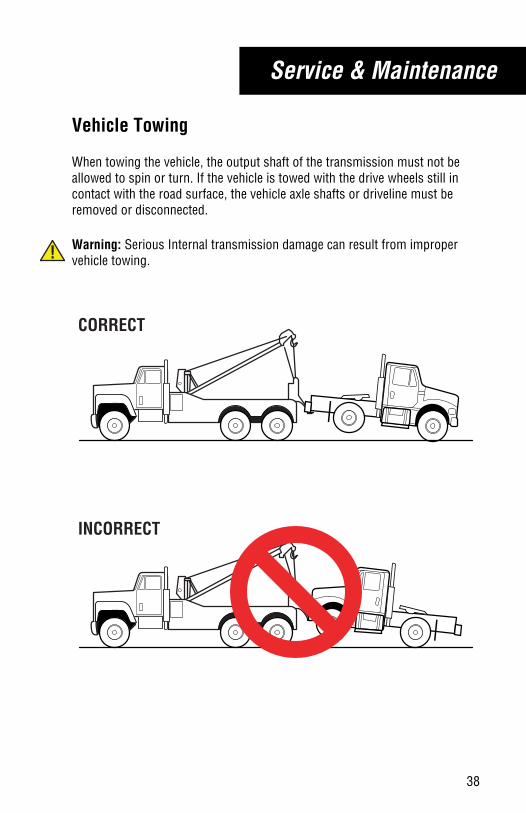
Vehicle Towing
When towing the vehicle, the output shaft of the transmission must not be allowed to spin or turn. If the vehicle is towed with the drive wheels still in contact with the road surface, the vehicle axle shafts or driveline must be removed or disconnected.
Warning: Serious Internal transmission damage can result from improper vehicle towing.!
CORRECT
INCORRECT

Copyright Eaton Cummins Automated Transmission Technologies, 2017.Eaton Cummins Automated Transmission Technologies hereby grant their customers,vendors, or distributors permissionto freely copy, reproduce and/ordistribute this document in printedformat. It may be copied only inits entirety without any changes ormodifications. THIS INFORMATIONIS NOT INTENDED FOR SALE ORRESALE, AND THIS NOTICE MUSTREMAIN ON ALL COPIES.
Note: Features and specificationslisted in this document are subject tochange without notice and representthe maximum capabilities of thesoftware and products with all optionsinstalled. Although every attempt hasbeen made to ensure the accuracy ofinformation contained within, Eatonmakes no representation about thecompleteness, correctness or accuracyand assumes no responsibility forany errors or omissions. Features andfunctionality may vary depending onselected options.
For spec’ing or service assistance, call 1-800-826-HELP (4357) or visit www.eaton.com/roadranger.In Mexico, call 001-800-826-4357.
Eaton Cummins Automated Transmission TechnologiesP.O. Box 4013Kalamazoo, MI 49003 USA800-826-HELP (4357)www.eaton.com/roadranger
Printed in USA
Roadranger: Eaton and trusted partners providing the best products and services in the industry, ensuring more time on the road.