EasyTouch 8 and 4 - Home - Pentair · 1620 Hawkins Ave., Sanford, NC 27330 • ... EasyTouch® 8...
80
IMPORTANT SAFETY INSTRUCTIONS READ AND FOLLOW ALL INSTRUCTIONS SAVE THESE INSTRUCTIONS EasyTouch ® 8 and 4 Pool and Spa Control System User’s Guide
Transcript of EasyTouch 8 and 4 - Home - Pentair · 1620 Hawkins Ave., Sanford, NC 27330 • ... EasyTouch® 8...
IMPORTANT SAFETY INSTRUCTIONSREAD AND FOLLOW ALL INSTRUCTIONSSAVE THESE INSTRUCTIONS
EasyTouch® 8 and 4Pool and Spa Control System
User’s Guide

© 2011 Pentair Water Pool and Spa, Inc. All rights reserved
This document is subject to change without notice
1620 Hawkins Ave., Sanford, NC 27330 • (800) 831-7133 • (919) 566-800010951 West Los Angeles Ave., Moorpark, CA 93021 • (800) 831-7133 • (805) 553-5000
EasyTouch®, IntelliChlor®, IntelliFlo®, IntelliPro®, QuickTouch®, IntelliBrite®, IntelliChem®,SpaCommand™, MagicStream®, SAm®, SAL®, FIBERworks® and ThermalFlo®, Photon Generator®,and Pentair Water Pool and Spa® are trademarks and/or registered trademarks of Pentair Water Pooland Spa, Inc. and/or its affiliated companies in the United States and/or other countries. Unless noted,names and brands of others that may be used in this document are not used to indicate an affiliation orendorsement between the proprietors of these names and brands and Pentair Water Pool and Spa, Inc.Those names and brands may be the trademarks or registered trademarks of those parties or others.
P/N 521044 - Rev A - 05/05/11
Download a PDF version of this manual to your computer from:
http://www.pentairpool.com/pdfs/EasyTouchSystemUG.pdf
i
EasyTouch Pool and Spa Control System User’s Guide
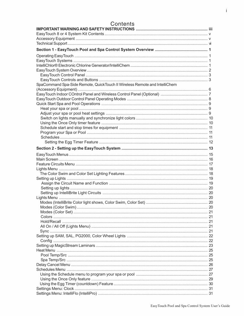
ContentsIMPORTANT WARNING AND SAFETY INSTRUCTIONS ................................................................ iiiEasyTouch 8 or 4 System Kit Contents ............................................................................................ vAccessory Equipment ...................................................................................................................... vTechnical Support ............................................................................................................................. vi
Section 1 - EasyTouch Pool and Spa Control System Overview ............................................... 1
Operating EasyTouch ....................................................................................................................... 1EasyTouch Systems ........................................................................................................................ 1IntelliChlor® Electronic Chlorine Generator/IntelliChem ..................................................................... 1EasyTouch System Overview............................................................................................................ 2 EasyTouch Control Panel ............................................................................................................. 3 EasyTouch Controls and Buttons ................................................................................................. 3SpaCommand Spa-Side Remote, QuickTouch II Wireless Remote and IntelliChem(Accessory Equipment) .................................................................................................................... 6EasyTouch Indoor COntrol Panel and Wireless Control Panel (Optional) .......................................... 7EasyTouch Outdoor Control Panel Operating Modes ........................................................................ 8Quick Start Spa and Pool Operations ............................................................................................... 9 Heat your spa or pool ................................................................................................................... 9 Adjust your spa or pool heat settings ........................................................................................... 9 Switch on lights manually and synchronize light colors ................................................................ 10 Using the Once Only timer feature ............................................................................................... 10 Schedule start and stop times for equipment ............................................................................... 11 Program your Spa or Pool ............................................................................................................ 11 Schedules .................................................................................................................................... 11 Setting the Egg Timer Feature ................................................................................................. 12
Section 2 - Setting up the EasyTouch System ............................................................................. 13
EasyTouch Menus ............................................................................................................................ 15Main Screen ..................................................................................................................................... 16Feature Circuits Menu ...................................................................................................................... 17Lights Menu ..................................................................................................................................... 18 The Color Swim and Color Set Lighting Features.......................................................................... 18Setting up Lights .............................................................................................................................. 19 Assign the Circuit Name and Function ........................................................................................ 19 Setting up lights ........................................................................................................................... 20 Setting up IntelliBrite Light Circuits .............................................................................................. 20Lights Menu ..................................................................................................................................... 20 Modes (IntelliBrite Color light shows, Color Swim, Color Set) ....................................................... 20 Modes (Color Swim) ..................................................................................................................... 20 Modes (Color Set) ........................................................................................................................ 21 Colors .......................................................................................................................................... 21 Hold/Recall .................................................................................................................................. 21 All On / All Off (Lights Menu) ........................................................................................................ 21 Sync ............................................................................................................................................. 21Setting up SAM, SAL, PG2000, Color Wheel Lights ........................................................................ 22 Config .......................................................................................................................................... 22Setting up MagicStream Laminars .................................................................................................... 23Heat Menu ....................................................................................................................................... 25 Pool Temp/Src ............................................................................................................................. 25 Spa Temp/Src .............................................................................................................................. 25Delay Cancel Menu .......................................................................................................................... 26Schedules Menu .............................................................................................................................. 27 Using the Schedule menu to program your spa or pool ................................................................ 27 Using the Once Only feature ........................................................................................................ 29 Using the Egg Timer (countdown) Feature .................................................................................... 30Settings Menu: Clock ....................................................................................................................... 31Settings Menu: IntelliFlo (IntelliPro) .................................................................................................. 31

ii
EasyTouch Pool and Spa Control System User’s Guide
Contents (Continued)
Settings Menu: IntelliFlo VS and IntelliFlo VSF+SVRS .................................................................... 33Settings Menu: IntelliFlo IntelliFlo VF ............................................................................................... 34Settings Menu: IntelliChlor ................................................................................................................ 35Settings Menu: IntelliChem .............................................................................................................. 38Settings Menu: Heat Pump COM (UltraTemp) .................................................................................. 40Settings Menu: Circuit Names .......................................................................................................... 41 Hi-Temp/Lo-Temp Controls for Single Body System...................................................................... 41EasyTouch Circuit Names (Complete List) ....................................................................................... 42Settings Menu: Circuit Functions ..................................................................................................... 43 Freeze Protection ........................................................................................................................ 43 Preset Circuit Function Names (Complete List) ............................................................................ 44Settings Menu: Custom Names........................................................................................................ 45Settings Menu: Valves ...................................................................................................................... 45Settings Menu: 2-Speed Pump ......................................................................................................... 46Settings Menu: Solar ........................................................................................................................ 46Settings Menu: Delays ..................................................................................................................... 47Settings Menu: F° / C° (Fahrenheit/Celsius) ..................................................................................... 48Settings Menu: iS4 Spa-Side Remote Controller ............................................................................... 48Settings Menu: 10 Button Spa-Side Remote Controller ..................................................................... 49Settings Menu: 10 Button Pump Crtl ................................................................................................ 50Settings Menu: QuickTouch (QT4) Wireless Remote ........................................................................ 51Settings Menu: Man Heat (Off/On) Manual Heat ............................................................................... 52Settings Menu: Calibration ............................................................................................................... 52Settings Menu: Erase EEPROM (Erase System Memory) ............................................................... 53Settings Menu: Set Password .......................................................................................................... 53Settings Menu: Wireless Addr .......................................................................................................... 54Spa Side [Off/On] ............................................................................................................................. 55Diagnostics Menu: Software Rev ...................................................................................................... 55Diagnostics Menu: Bootloader Rev ................................................................................................... 55Diagnostics Menu: Self Test ............................................................................................................. 56Diagnostics Menu: Chlorinator .......................................................................................................... 57Diagnostics Menu: Water Temp........................................................................................................ 57Diagnostics Menu: Solar Temp ......................................................................................................... 57Diagnostics Menu: Air Temp ............................................................................................................. 58Diagnostics Menu: Cir Name: [Off/On] .............................................................................................. 58Diagnostics Menu: Reset System .................................................................................................... 58Diagnostics Menu: Flash Update ...................................................................................................... 58
Section 3 - Troubleshooting .......................................................................................................... 59
Frequently Asked Questions (FAQ) .............................................................................................. 59 EasyTouch Error Messages ......................................................................................................... 60 Self Test Error Codes ............................................................................................................... 60 Error Code Table ...................................................................................................................... 60 IntelliChlor Error Messages .......................................................................................................... 61 System Problem Diagnosis .......................................................................................................... 62 First Time System Start-Up .......................................................................................................... 65 Check Electronics ................................................................................................................... 65 System Test ............................................................................................................................ 65 Testing the Auxiliary Relays ......................................................................................................... 65 Setting up the EasyTouch wireless control panel for the first time ................................................ 66 Synchronizing control panels ....................................................................................................... 67Wiring UltraTemp to EasyTouch........................................................................................................ 67
Glossary .......................................................................................................................................... 68
iii
EasyTouch Pool and Spa Control System User’s Guide
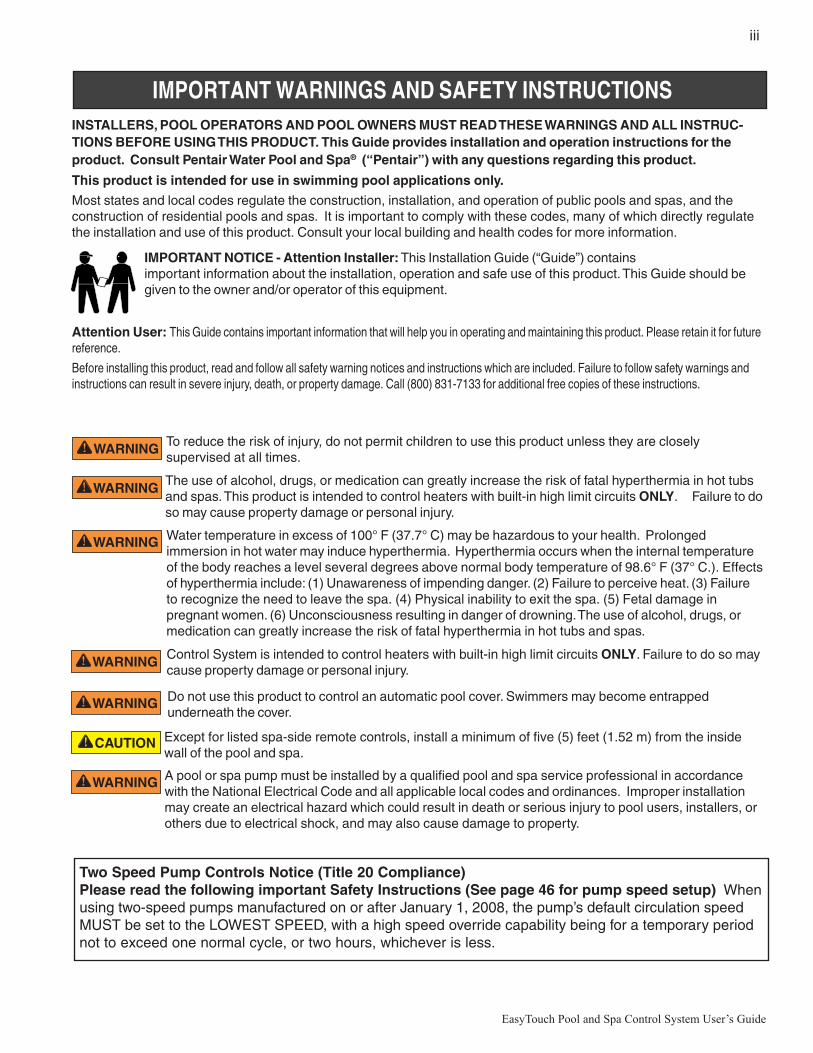
IMPORTANT WARNINGS AND SAFETY INSTRUCTIONSINSTALLERS, POOL OPERATORS AND POOL OWNERS MUST READ THESE WARNINGS AND ALL INSTRUC-TIONS BEFORE USING THIS PRODUCT. This Guide provides installation and operation instructions for theproduct. Consult Pentair Water Pool and Spa® (“Pentair”) with any questions regarding this product.
This product is intended for use in swimming pool applications only.
Most states and local codes regulate the construction, installation, and operation of public pools and spas, and theconstruction of residential pools and spas. It is important to comply with these codes, many of which directly regulatethe installation and use of this product. Consult your local building and health codes for more information.
Attention User: This Guide contains important information that will help you in operating and maintaining this product. Please retain it for futurereference.
Before installing this product, read and follow all safety warning notices and instructions which are included. Failure to follow safety warnings andinstructions can result in severe injury, death, or property damage. Call (800) 831-7133 for additional free copies of these instructions.
IMPORTANT NOTICE - Attention Installer: This Installation Guide (“Guide”) containsimportant information about the installation, operation and safe use of this product. This Guide should begiven to the owner and/or operator of this equipment.
To reduce the risk of injury, do not permit children to use this product unless they are closelysupervised at all times.
Control System is intended to control heaters with built-in high limit circuits ONLY. Failure to do so maycause property damage or personal injury.
Do not use this product to control an automatic pool cover. Swimmers may become entrappedunderneath the cover.
Except for listed spa-side remote controls, install a minimum of five (5) feet (1.52 m) from the insidewall of the pool and spa.
Two Speed Pump Controls Notice (Title 20 Compliance)Please read the following important Safety Instructions (See page 46 for pump speed setup) Whenusing two-speed pumps manufactured on or after January 1, 2008, the pump’s default circulation speedMUST be set to the LOWEST SPEED, with a high speed override capability being for a temporary periodnot to exceed one normal cycle, or two hours, whichever is less.
Water temperature in excess of 100° F (37.7° C) may be hazardous to your health. Prolongedimmersion in hot water may induce hyperthermia. Hyperthermia occurs when the internal temperatureof the body reaches a level several degrees above normal body temperature of 98.6° F (37° C.). Effectsof hyperthermia include: (1) Unawareness of impending danger. (2) Failure to perceive heat. (3) Failureto recognize the need to leave the spa. (4) Physical inability to exit the spa. (5) Fetal damage inpregnant women. (6) Unconsciousness resulting in danger of drowning. The use of alcohol, drugs, ormedication can greatly increase the risk of fatal hyperthermia in hot tubs and spas.
A pool or spa pump must be installed by a qualified pool and spa service professional in accordancewith the National Electrical Code and all applicable local codes and ordinances. Improper installationmay create an electrical hazard which could result in death or serious injury to pool users, installers, orothers due to electrical shock, and may also cause damage to property.
The use of alcohol, drugs, or medication can greatly increase the risk of fatal hyperthermia in hot tubsand spas. This product is intended to control heaters with built-in high limit circuits ONLY. Failure to doso may cause property damage or personal injury.

iv
EasyTouch Pool and Spa Control System User’s Guide
General Installation Information1. All work must be performed by a licensed electrician, and must conform to all national, state, and local
codes.
2. Install to provide drainage of compartment for electrical components.
3. If this system is used to control underwater lighting fixtures, a ground-fault interrupter (GFCI) must beprovided for these fixtures. Conductors on the load side of the ground-fault circuit-interrupter shall notoccupy conduit, junction boxes or enclosures containing other conductors unless such conductors arealso protected by a ground-fault circuit-interrupter. Refer to local codes for details.
4. A terminal bar stamped is located inside the supply terminal box. To reduce the risk of electricshock, this terminal must be connected to the grounding means provided in the electric supply servicepanel with a continuous copper wire equivalent in size to the circuit conductors supplying thisequipment (no smaller than 12 AWG or 3.3 mm). The bonding lug(s) provided on this unit are intendedto connect a minimum of one No. 8 AWG for US installation and two No. 6 AWG for Canadianinstallations solid copper conductor between this unit and any metal equipment, metal enclosures orelectrical equipment, metal water pipe, or conduit within 5 feet (1.5 m) of the unit.
5. The electrical supply for this product must include a suitably rated switch or circuit breaker to open allungrounded supply conductors to comply with in accordance with the National Electrical Code (NEC),NFPA 70 or the Canadian Electrical Code (CEC), CSA C22.1. All applicable local installation codesand ordinances must also be adhered to. The disconnecting means must be readily accessible to thetub occupant but installed at least five (5) feet (1.52 m) from the inside wall of the pool.
6. GAS HEATER: This automation control system is designed to supply high voltage (120 VAC / 240VAC) to a gas heater and override the thermostat in the heater’s control circuit. This automation controlsystem is intended to control gas heaters with a high temperature limit switch(s) safety circuit.
IMPORTANT WARNINGS AND SAFETY INSTRUCTIONS
For information about the Virginia Graeme Baker Pool and Spa Safety Act, contact the Consumer Product SafetyCommission at (301) 504-7908 or visit www.cpsc.gov.
NOTE: Always turn off all power to the pool pump before installing the main drain cover or working on any suctionoutlet.

v
EasyTouch Pool and Spa Control System User’s Guide
EasyTouch 4 Indoor ControlPanel (P/N 520548)
EasyTouch 8 Indoor ControlPanel (P/N 520549)
POWER ON
EasyTouch Wireless Control Panel(8 circuit) (P/N 520547)
EasyTouch® 8 and 4 Pool and Spa Control System Kit ContentsThe following items are included in the EasyTouch® 8 and EasyTouch 4 control system kit whichmay also include the IntelliChlor cell.
• EasyTouch control panel (mounted in the load center)• EasyTouch load center enclosure• Two motorized valve actuators (CVA-24T P/N 263045) - Not included with single-body
system• Water sensor with 25 foot cable, o-ring and hose clamp (P/N 520272)• Air sensor with 25 foot cable (P/N 520272)• EasyTouch 8 and EasyTouch 4 Pool and spa Control System Installation Guide
(this manual)
Optional Equipment
• IntelliChlor® Electronic Chlorine Generator Electrolytic Cell model IC20 (P/N 520554) orIC40 (P/N 520555)
• IntelliChem® no-pump (P/N 521357), one-pump (P/N 521356), two-pump (P/N 521355)• IntelliChlor User’s Guide (P/N 520589)• For EasyTouch system operating instructions, refer to the EasyTouch User’s Guide
(P/N 521044)
EasyTouch Accessory Equipment
Technical Support
Contact Technical Support at:
Tel: (800) 831-7133)
Hours: 8 A.M. to 5 P.M.
Fax: (919) 566-8920
Web sites: www.pentairpool.com and www.staritepool.com

vi
EasyTouch Pool and Spa Control System User’s Guide
EasyTouch Accessory Equipment (Continued)
EasyTouch Wireless Control Panel, 4 circuits (P/N 520546)EasyTouch Wireless Control Panel, 8 circuits (P/N 520547)SpaCommand, 10 Ten-Function Spa-Side remote, 150 ft. cable (P/N 521176)Two-Speed Three HP Relay up to three additional valve actuators (P/N 520198)Three HP Power Relay (P/N 520106)QuickTouch four-function wireless remote kit with transceiver assembly (P/N 520148)QuickTouch II four-function wireless remote kit with transceiver assembly (P/N 521245)IntelliChem Controller (P/N 521356)IntelliChlor Acid Cleaning Kit (P/N 520670)IntelliChlor Spacer pass-through cell for new pool start-up (P/N 520588)
EasyTouch Model Part Numbers
EASYTOUCH SYSTEMS WITHOUT INTELLICHLOR TRANSFORMER BUILT-IN520591 EasyTouch 4P - Single Body (base system - no ICP, no actuators)520703 EasyTouch 8P - Single Body (base system - no ICP, no actuators)
520538 EasyTouch 4 - Pool/Spa (base system - no ICP, 2 actuators)
520540 EasyTouch 8 - Pool/Spa (base system - no ICP, 2 actuators)
EASYTOUCH SYSTEMS WITH INTELLICHLOR TRANSFORMER AND INTELLICHLOR CELL520592 EasyTouch 4PSC-IC20 - Single Body (includes SCG integration & IC20 cell)520593 EasyTouch 4PSC-IC40 - Single Body (includes SCG integration & IC40 cell)
520704 EasyTouch 8PSC-IC20 - Single Body (includes SCG integration & IC20 cell)
520705 EasyTouch 8PSC-IC40 - Single Body (includes SCG integration & IC40 cell)520542 EasyTouch 4SC-IC20 - Pool/Spa (includes SCG integration & IC20 cell, 2 actuators)
520543 EasyTouch 4SC-IC40 - Pool/Spa (includes SCG integration & IC40 cell, 2 actuators)
520544 EasyTouch 8SC-IC20 - Pool/Spa (includes SCG integration & IC20 cell, 2 actuators)520545 EasyTouch 8SC-IC40 - Pool/Spa (includes SCG integration & IC40 cell, 2 actuators)
521150 EasyTouch 8SC-IC60 - Pool/Spa (includes SCG integration & IC60 cell, 2 actuators)
CANADIAN EASYTOUCH SYSTEMS520914 EasyTouch 4P-C - Single Body (salt ready system, cell must be ordered separately)
520915 EasyTouch 8-C - Pool/Spa (salt ready system, cell must be ordered separately)520911 IntelliChlor IC20 cell for Canada
520912 IntelliChlor IC40 cell for Canada
1
EasyTouch Pool and Spa Control System User’s Guide
Section 1EasyTouch System Overview
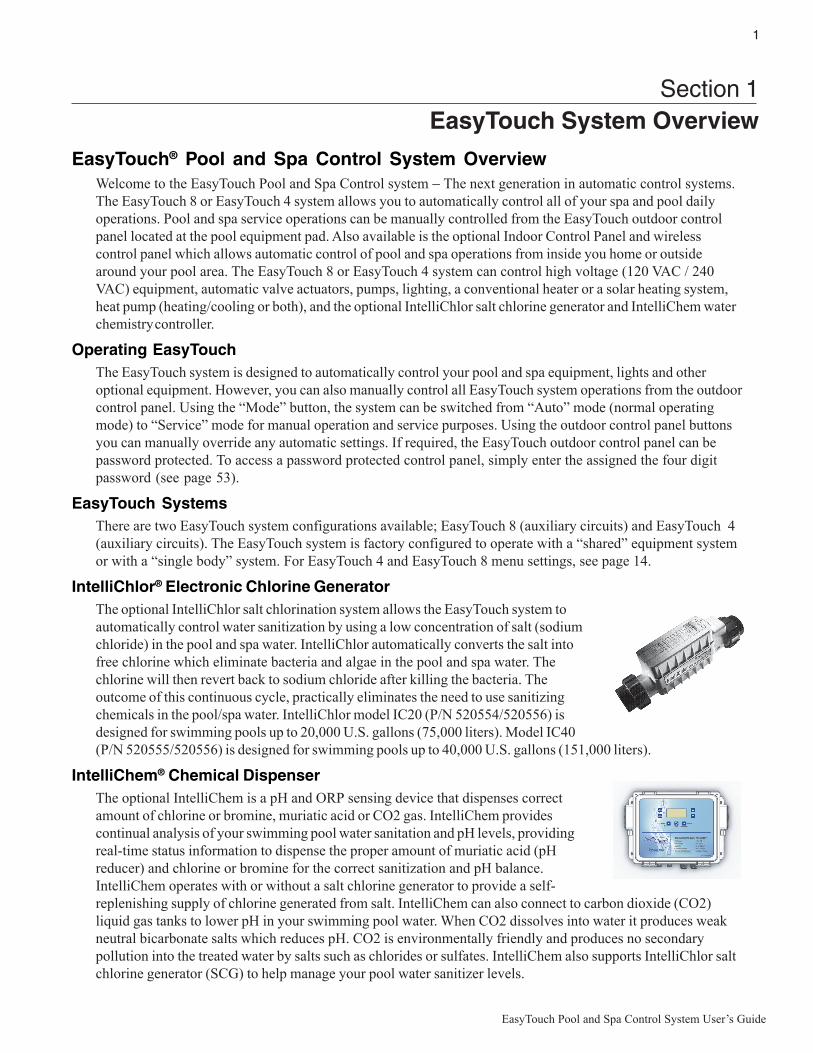
EasyTouch® Pool and Spa Control System OverviewWelcome to the EasyTouch Pool and Spa Control system − The next generation in automatic control systems.The EasyTouch 8 or EasyTouch 4 system allows you to automatically control all of your spa and pool dailyoperations. Pool and spa service operations can be manually controlled from the EasyTouch outdoor controlpanel located at the pool equipment pad. Also available is the optional Indoor Control Panel and wirelesscontrol panel which allows automatic control of pool and spa operations from inside you home or outsidearound your pool area. The EasyTouch 8 or EasyTouch 4 system can control high voltage (120 VAC / 240VAC) equipment, automatic valve actuators, pumps, lighting, a conventional heater or a solar heating system,heat pump (heating/cooling or both), and the optional IntelliChlor salt chlorine generator and IntelliChem waterchemistry controller.
Operating EasyTouchThe EasyTouch system is designed to automatically control your pool and spa equipment, lights and otheroptional equipment. However, you can also manually control all EasyTouch system operations from the outdoorcontrol panel. Using the “Mode” button, the system can be switched from “Auto” mode (normal operatingmode) to “Service” mode for manual operation and service purposes. Using the outdoor control panel buttonsyou can manually override any automatic settings. If required, the EasyTouch outdoor control panel can bepassword protected. To access a password protected control panel, simply enter the assigned the four digitpassword (see page 53).
EasyTouch SystemsThere are two EasyTouch system configurations available; EasyTouch 8 (auxiliary circuits) and EasyTouch 4(auxiliary circuits). The EasyTouch system is factory configured to operate with a “shared” equipment systemor with a “single body” system. For EasyTouch 4 and EasyTouch 8 menu settings, see page 14.
IntelliChlor® Electronic Chlorine GeneratorThe optional IntelliChlor salt chlorination system allows the EasyTouch system toautomatically control water sanitization by using a low concentration of salt (sodiumchloride) in the pool and spa water. IntelliChlor automatically converts the salt intofree chlorine which eliminate bacteria and algae in the pool and spa water. Thechlorine will then revert back to sodium chloride after killing the bacteria. Theoutcome of this continuous cycle, practically eliminates the need to use sanitizingchemicals in the pool/spa water. IntelliChlor model IC20 (P/N 520554/520556) isdesigned for swimming pools up to 20,000 U.S. gallons (75,000 liters). Model IC40(P/N 520555/520556) is designed for swimming pools up to 40,000 U.S. gallons (151,000 liters).
IntelliChem® Chemical DispenserThe optional IntelliChem is a pH and ORP sensing device that dispenses correctamount of chlorine or bromine, muriatic acid or CO2 gas. IntelliChem providescontinual analysis of your swimming pool water sanitation and pH levels, providingreal-time status information to dispense the proper amount of muriatic acid (pHreducer) and chlorine or bromine for the correct sanitization and pH balance.IntelliChem operates with or without a salt chlorine generator to provide a self-replenishing supply of chlorine generated from salt. IntelliChem can also connect to carbon dioxide (CO2)liquid gas tanks to lower pH in your swimming pool water. When CO2 dissolves into water it produces weakneutral bicarbonate salts which reduces pH. CO2 is environmentally friendly and produces no secondarypollution into the treated water by salts such as chlorides or sulfates. IntelliChem also supports IntelliChlor saltchlorine generator (SCG) to help manage your pool water sanitizer levels.

2
EasyTouch Pool and Spa Control System User’s Guide
EasyTouch System Overview
• PumpsFilter, Cleaner, Spa Jet -1.5 HP 120 VAC3 HP 277 VAC20 FLA/120 LRA,120 VAC17 FLA/102 LRA,277 VAC
• Pool/Spa Lights1.5 KW 120 VACTungsten4.8 KW 240 VACTungsten20 AMP, 277 VACBallast
• Pool/Spa ValveSuction and return.24 VAC valve actuator,shared equipment only
• Auxiliary Valves(Qty. 2) A and B
• HeaterGas or electric
• Heat Pump(UltraTemp®)Heating or cooling
• Relays25 AMP, 277 VAC
Temperature Sensors(Water, Air and Solar)
Electric Heater -Connects to plug J16
on EasyTouchmotherboard
EasyTouch 8 IndoorControl Panel (P/N 520549)(Optional)
Low Voltage (DC)circuit breakers
EasyTouch Outdoor Control Panel
Connects toEasyTouchmotherboard
EasyTouch WirelessControl Panel (8 circuit)(P/N 520547) (Optional)
IntelliChlor (SCG)circuit breaker
• IntelliChlor Salt Chlorine Generator (SCG)• IC20 P/N 520554 520556• IC40 P/N 520555/520556 (see page 26)• IntelliChem Controller: P/N 521357 (no pump),
P/N 521356 (one pump), P/N 521355 (two pump)(see page 38)
QuickTouch II WirelessRemote (P/N 521245)(Optional)
SpaCommand Spa-Side Remote(P/N 521176) (Optional)
IntelliChem ControllerP/N 521356 (Optional)
3
EasyTouch Pool and Spa Control System User’s Guide
EasyTouch Control Panel
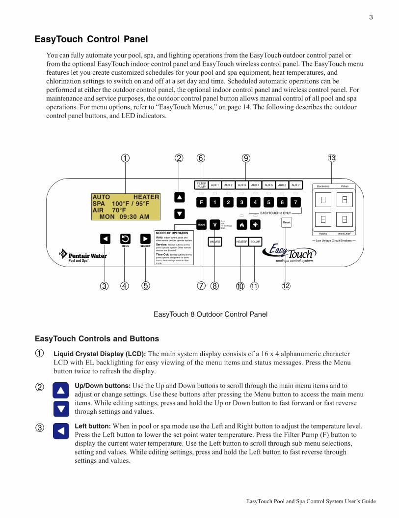
You can fully automate your pool, spa, and lighting operations from the EasyTouch outdoor control panel orfrom the optional EasyTouch indoor control panel and EasyTouch wireless control panel. The EasyTouch menufeatures let you create customized schedules for your pool and spa equipment, heat temperatures, andchlorination settings to switch on and off at a set day and time. Scheduled automatic operations can beperformed at either the outdoor control panel, the optional indoor control panel and wireless control panel. Formaintenance and service purposes, the outdoor control panel button allows manual control of all pool and spaoperations. For menu options, refer to “EasyTouch Menus,” on page 14. The following describes the outdoorcontrol panel buttons, and LED indicators.
EasyTouch Controls and Buttons
Liquid Crystal Display (LCD): The main system display consists of a 16 x 4 alphanumeric characterLCD with EL backlighting for easy viewing of the menu items and status messages. Press the Menubutton twice to refresh the display.
Up/Down buttons: Use the Up and Down buttons to scroll through the main menu items and toadjust or change settings. Use these buttons after pressing the Menu button to access the main menuitems. While editing settings, press and hold the Up or Down button to fast forward or fast reversethrough settings and values.
Left button: When in pool or spa mode use the Left and Right button to adjust the temperature level.Press the Left button to lower the set point water temperature. Press the Filter Pump (F) button todisplay the current water temperature. Use the Left button to scroll through sub-menu selections,setting and values. While editing settings, press and hold the Left button to fast reverse throughsettings and values.
➀
➁
➂
EasyTouch 8 Outdoor Control Panel
➁
➂ ➃ ➄
➅
➆ ➇
➈
➉
➀
AUTO HEATERSPA 100°F / 95°FAIR 70°F MON 09:30 AM
1211
13

4
EasyTouch Pool and Spa Control System User’s Guide
Controls and buttons (Continued)
Menu/back button: Use this button to access, save and exit from a current menu or sub-menusettings. Also, while in a menu or sub-menu items, use this button to go back to a previous menulevel or item. If no menu activity is detected after five minutes, the main screen is displayed. Allmenu settings are permanently saved and retained in the control panel even after power is removedfrom the control panel. Control panel buttons are disabled while in the menu mode.
Right button: When in pool or spa mode use the Left and Right button to adjust the temperaturelevel. Press the Right button to raise the set point water temperature. Press the Filter Pump (F)button to display the current water temperature. Use the Right button to select a sub-menu item forediting. After pressing the Menu button to access the main menu items, use the Right button to selectthe menu item and access the sub-menu items for adjustment. While editing a settings, press andhold the Right button to fast forward through settings and values.
Filter Pump (F) button/LED: Switches a single speed filter pump on and off in “Pool” or “Spa”mode. Press the Valves (V) button to toggle between “Pool” and “Spa” mode and rotate valves. If“Heater” is enabled in the “Heat” menu (see page 25), pressing the Filter Pump button will alsoenable the selected heat source (Heater/Solar LED on). The default time before the filter pump willswitch off is 12 hours. This button operates in “Auto” or “Service” mode.
Single-Speed Filter Pump: If the pump is currently off, press the Filter Pump button (LED on) toswitch the pump on. Press the Filter Pump button again to switch the pump off. However, if theheater is operating, and a delay is enabled for valves, this allows the heater to cool down (heatercool-down), then when you press the F button to switch off the pump, only the heater will turn off,then the filter pump will automatically switch off after 10 minutes to allow the heater to cool down.Pentair Water Pool and Spa heaters do not require a cool down time. To override the “heater cool-down,” press the Filter Pump button again to switch off the pump.
Two-Speed Filter Pump: Press the Filter Pump button (LED on) to switch the two-speed pump onin high speed. If you switch the pump off to low speed shortly after switching it to high speed, thefilter pump will automatically remain in high speed for a few minutes before switching back to lowspeed to allow the pump to prime and establish normal water flow. In order to use the “2-SpeedPump” menu assignments (see page 46), the 2-Speed relay option must be installed in theEasyTouch Load Center.
Freeze Protection: This function protects the pool, plumbing, and equipment against freeze damage.If the outside air temperature sensor falls below 36° F, “Freeze Protection” is activated and the FilterPump relay is switched on to circulate the pool water. To enable freeze protection for a circuit, see“Settings Menu: Circuit Function, ” on page 43.
Mode button: Use this button for service purposes to manually control the EasyTouch system. Pressthis button once activate “Service” mode, to allow AUX circuit buttons, Filter Pump, Valves, Heaterand Solar buttons to be operated manually. Press the button a second time to enable “Timeout”mode. This mode is similar to “Service” mode except that the system will automatically return tonormal operation (Auto) after three hours. Press the button a third time to return the system to“AUTO” mode. The current operating status is shown in the LCD display. The menu buttons,remote controllers, and menu scheduled operations are disabled (except for switching off equipmentmanually for emergencies) while the system is in “Service” mode.
Auto: In Auto (automatic) mode the system is in normal operating mode and is controlled by themain control panel LCD menu features.
Service: Use this mode to service pool equipment and to operate equipment manually.
Timeout: Same functionality as “Service” mode, except that the system will automatically return tonormal operation (Auto) after three hours.
➃
➄
➅
➆
MENU

5
EasyTouch Pool and Spa Control System User’s Guide
Controls and buttons (Continued)
Valves (V) - (Pool/Spa/Fill (Spillway)/Drain) button: When in normal operating mode, theValves (V) button is in “Pool” mode. In this mode the valves are automatically rotated so thatonly the pool water is circulated through the system and the filter pump is activated. Pressing thisbutton once enables “Spa” mode and activates the filter pump to circulate only spa waterthrough the system. “Fill/Spillway” and “Drain” mode can only be used while in “Service” mode(See Mode button for details). “Fill/Spillway” and “Drain” mode are used when cleaning the spa.Pressing the Valves (V) button again returns the system to “Pool” mode. Note that the filterpump will switch off while the pool/spa valves are rotating into position. The current operatingmode is shown in the LCD display. Note: The Valves button (Pool, Spa, Fill (Spillway),Drain) button has no function in “Pool only” or “Spa only” systems. For an EasyTouchsingle body system, “Pool” and “Spa” modes are Lo- Temp (Pool) and Hi-Temp (Spa)temperature controls. For more information, see “Hi-Temp/Lo-Temp Controls for SingleBody Systems,” page 41.
Aux 1 - 7 buttons/LEDs: Auxiliary output circuit buttons operate the pool and spa system valves,lights and other equipment. These auxiliary circuits are assigned in the “Circuit Function” menu, seepage 39 for details. There are three auxiliary circuits (AUX 1- 3) on the EasyTouch 4 outdoorcontrol panel and seven auxiliary circuits (AUX 1- 7) on EasyTouch 8 outdoor control panel. TheSolar button can also be used for an “extra” auxiliary circuit if the Solar circuit is not being for solarequipment. Labels can be affixed next to each auxiliary button to identify the circuit function. Labelscan be affixed over each auxiliary button to identify the circuit function. When an auxiliary circuit isactivated or the button is pressed, the LED is on. Pressing an auxiliary circuit button will activate thecorresponding circuit in either “Auto” or “Service” mode. When a circuit relay is switched onmanually, it remains on until either you switch it off manually, or the next time the relay is scheduledto be switched off. For example, if the filter pump is scheduled to automatically run from 9:00 AM to5:00 PM daily then the filter pump is switched on manually at 9:00 PM, it will run continuously untilthe next day at 6:00 PM then switch off. The schedule will then continue from then on.
Heater (Flame) button/LED: This button is only used in “Service” mode for manual heat on and offcontrol. The Heater LED will be on if “Heater” is enabled in the “Heat” menu setting (see page 25).Switching the heater on automatically controls the output between a “forced off” state and a normalautomatic thermostatic control operating state. The heater will continue heating the water until theheater’s current highest set point temperature triggers the heater sensor (approximately 104° F).Note that the Heater button does not activate the pump. Do not activate the heater without runningthe pump. The heater will not run if water flow is not detected.
Solar (Sun) button/LED and (Aux Extra): In solar mode this button is only used in “Service” modefor manual solar heat on and off control. The Solar LED will be on if “Solar” is enabled in the“Heat” menu setting. Solar must also be enabled in the “Solar” menu. Use the Solar button tomanually switch the heater control output between a “forced off” state and a normal automaticthermostatic control operating state. When this button is pressed the solar relay is switched on toactivate a booster pump if installed and activates valves to rotate to divert water through solarheating panels. If solar equipment is not being used, this button can also be used to switch the AUXEXTRA circuit on and off.
Reset button: Press this button to reinitialize the EasyTouch outdoor control panel.
IntelliChlor circuit breaker (SCG system only): The circuit breaker opens in case the circuit isshorted or overloaded. Press circuit breaker to reset power to the IntelliChlor.
Low voltage circuit breakers: Three amp circuit breakers protect the low voltage systemmotherboard circuits, relays and valves.
➇
➈
➉

6
EasyTouch Pool and Spa Control System User’s Guide
SpaCommand Spa-Side RemoteThe optional 10-button SpaCommand spa-side remote cancontrol ten pool/spa functions from the spa location. The spatemperature can be adjusted from the SpaCommand. TheSpaCommand spa-side remote also supports IntelliFlo®pump speed and flow control. The remote is a double-insulated device for use with EasyTouch®, IntelliTouch®and Compool® (CPxxxx) pool and spa control systems. Seepage 49 for details.
QuickTouch® II Wireless RemoteThe optional hand held QuickTouch II wireless remote can control up to four pool/spa circuits. Each of thefour functions on the remote has an on and an off button. For more information, see page 51.
SpaCommand Spa-Side Remote (P/N 521245)
The optional IntelliChem™ water chemistry controller is a pH and ORPsensing device that dispenses correct amount of chlorine or bromine,muriatic acid or CO2 gas. IntelliChem provides continual analysis ofyour swimming pool water sanitation and pH levels, providing real-timestatus information to dispense the proper amount of muriatic acid (pHreducer) and chlorine or bromine for the correct sanitization and pHbalance. IntelliChem operates with or without a salt chlorine generatorto provide a self-replenishing supply of chlorine generated from salt.IntelliChem can also connect to carbon dioxide (CO2) liquid gas tanksto lower pH in your swimming pool water. See page 38 for details.
IntelliChem Water Chemistry Controller
QuickTouch II Wireless Remote (P/N 521245)
IntelliChem Controller (P/N 521245)

7
EasyTouch Pool and Spa Control System User’s Guide
EasyTouch Indoor Control Panel and Wireless Control Panel (Optional)
The EasyTouch Wireless or the Indoor Control Panel allows you to control your pool and spa daily operationsfrom around your pool area or inside your home. Use the “P” (Pool) and “Spa” (Pool) buttons to heat andfilter your pool and spa. The Indoor Control Panel connects to the EasyTouch motherboard in the load center.For more information refer to the EasyTouch Indoor Control Panel User’s Guide (P/N 520616) and theEasyTouch Wireless Control Panel User’s Guide (P/N 520688).
EasyTouch wireless control panel (EasyTouch 8) - (P/N 520547)
For details about thecontrol panel LCDstatus messages,
see page 8
AUTO HEATERSPA 100°F / 95°FAIR 70°F MON 09:30 AM
Seven user definedauxiliary circuits.Buttons switch theassigned circuitfunction on/off (12hour time-out). Downarrow button can alsobe used for an “extra”auxiliary circuit if solarequipment is not beingused
Spa (Hi-Temp) Button: Switches the filterpump on, rotates valve actuator (to isolatespa water from pool water), and switchesthe heater on. Hi-Temp (EasyTouch singlebody system) sets the high temperaturesettings for the spa.
Circuit LEDCircuit name label
Spa (Hi-Temp) Button:Switches the filterpump on, rotates valveactuator (to isolate spawater from pool water),and switches theheater on. Hi-Temp(EasyTouch singlebody system) sets thehigh temperaturesettings for thespa.
Pool (Lo-Temp) Button:Switches the filter pump on,
rotates valve actuator (to isolatepool water from spa water), and
switches heater on.Lo-Temp (EasyTouch single body
system) sets the low tempera-ture settings for the pool (see
page 41)
Pool (Lo-Temp) Button:Switches the filter pump
on, rotates valveactuator (to isolate poolwater from spa water),
and switches heater on.Lo-Temp (EasyTouchsingle body system)
sets the low temperaturesettings for the pool.
EasyTouch indoor control panel (EasyTouch 8) - (P/N 520549)
AUTO HEATERSPA 95°F / 100°FAIR 70°FMON 09:30 AM
POWER ON
Seven userdefined auxiliarycircuits. Buttonsswitch the as-signed circuitfunction on/off(12 hour time-out)Down arrow buttoncan also be usedfor an “extra”auxiliary circuit ifsolar equipment isnot being used
8
EasyTouch Pool and Spa Control System User’s Guide
AUTO HEATERSPA 100°F / 95°FAIR 70°F MON 09:30 AM
EasyTouch Outdoor Control Panel Operating Modes
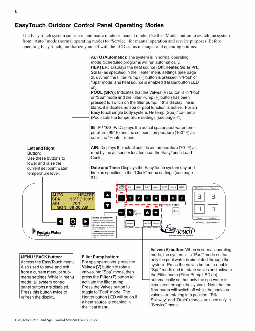
The EasyTouch system can run in automatic mode or manual mode. Use the “Mode” button to switch the systemfrom “Auto” mode (normal operating mode) to “Service” for manual operation and service purposes. Beforeoperating EasyTouch, familiarize yourself with the LCD status messages and operating buttons.
AUTO (Automatic): The system is in normal operatingmode. Scheduled programs will run automatically.HEATER: Displays the heat source (Off, Heater, Solar Prf.,Solar) as specified in the Heater menu settings (see page25). When the Filter Pump (F) button is pressed in “Pool” or“Spa” mode, and heat source is enabled (Heater button LEDon).POOL (SPA): Indicates that the Valves (V) button is in “Pool”or “Spa” mode and the Filter Pump (F) button has beenpressed to switch on the filter pump. If this display line isblank, it indicates no spa or pool function is active. For anEasyTouch single body system, Hi-Temp (Spa) / Lo-Temp(Pool) sets the temperature settings (see page 41)
95° F / 100° F: Displays the actual spa or pool water tem-perature (95° F) and the set point temperature (100° F) asset in the “Heater” menu.
AIR: Displays the actual outside air temperature (70° F) asread by the air sensor located near the EasyTouch LoadCenter.
Date and Time: Displays the EasyTouch system day andtime as specified in the “Clock” menu settings (see page31).
Valves (V) button: When in normal operatingmode, the system is in “Pool” mode so thatonly the pool water is circulated through thesystem. Press the Valves button to enable“Spa” mode and to rotate valves and activatethe Filter pump (Filter Pump LED on)automatically so that only the spa water iscirculated through the system. Note that thefilter pump will switch off while the pool/spavalves are rotating into position. “Fill/Spillway” and “Drain” modes are used only in“Service” mode.
MENU / BACK button:Access the EasyTouch menu.Also used to save and exitfrom a current menu or sub-menu settings. While in menumode, all system controlpanel buttons are disabled.Press this button twice torefresh the display.
AUTO HEATERSPA 95°F / 100°FAIR 70°F MON 09:30 AM
Filter Pump button:For spa operations, press theValves (V) button to rotatevalves into “Spa” mode, thenpress the Filter (F) button toactivate the filter pump.Press the Valves button totoggle to “Pool” mode. TheHeater button LED will be on ifa heat source is enabled inthe Heat menu.
Left and RightButton:Use these buttons tolower and raise thecurrent set point watertemperature level.
9
EasyTouch Pool and Spa Control System User’s Guide
Quick Start - Spa and Pool Operations (Shared Equipment)
The following describes how to adjust heat temperature for the spa and pool water, schedule a daily run timefor the pool/spa filter pump and control lights for shared equipment.
Heat your spa or pool
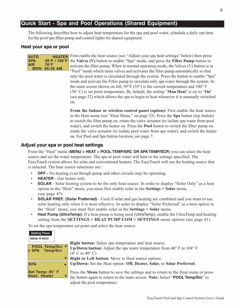
First enable the heat source (see “Adjust your spa heat settings” below) then pressthe Valves (V) button to enable “Spa” mode, and press the Filter Pump button toactivate the filter pump. When in normal operating mode, the Valves (V) button is in“Pool” mode which turns valves and activates the filter pump automatically so thatonly the pool water is circulated through the system. Press the button to enable “Spa”mode and activate the Filter pump to circulate only spa water through the system. Inthe main screen shown on left, 95°F (35°) is the current temperature and 100° F(38° C) is set point temperature. By default, the setting “Man Heat’ is set to “On”(see page 52) which allows the spa to begin to heat whenever it is manually switchedon.
From the Indoor or wireless control panel (option): First enable the heat sourcein the Heat menu (see “Heat Menu,” on page 25). Press the Spa button (top button)to switch the filter pump on, rotate the valve actuator (to isolate spa water from poolwater), and switch the heater on. Press the Pool button to switch the filter pump on,rotate the valve actuator (to isolate pool water from spa water), and switch the heateron. For Pool and Spa button location, see page 7.
Adjust your spa or pool heat settingsFrom the “Heat” menu (MENU > HEAT > POOL TEMP/SRC OR SPA TEMP/SCR) you can select the heatsource and set the water temperature. The spa or pool water will heat to the settings specified. TheEasyTouch system allows for solar and conventional heaters. The EasyTouch will use the heating source thatis selected. The heat source selections are:
• OFF - No heating even though pump and other circuits may be operating.• HEATER - Gas heater only.• SOLAR - Solar heating system to be the only heat source. In order to display “Solar Only” as a heat
option in the “Heat” menu, you must first enable solar in the Settings > Solar menu,(see page 47).
• SOLAR PREF. (Solar Preferred) - Used if solar and gas heating are combined and you want to usesolar heating only when it is most effective. In order to display “Solar Preferred” as a heat option inthe “Heat” menu, you must first enable solar in the Settings > Solar menu.
• Heat Pump (UltraTemp): If a heat pump is being used (UltraTemp), enable the UltraTemp and heatingsetting from the SETTINGS > HEAT PUMP COM > SETTINGS menu options (see page 41).
To set the spa temperature set point and select the heat source:
Right button: Select spa temperature and heat source.Up/Down button: Adjust the spa water temperature from 40° F to 104° F(4° C to 40° C)Right or Left button: Move to Heat source options.Up/Down: Set the Heat option: Off, Heater, Solar, or Solar Preferred.
Press the Menu button to save the settings and to return to the Heat menu or pressthe button again to return to the main screen. Note: Select “POOL Temp/Src” toadjust the pool temperature.
AUTO HEATERSPA 95°F / 100°FAIR 70°F MON 09:30 AM
POOL Temp/Src SPA Temp/Src
SPA
Set Temp: 85° FHeat: Heater
Getting There
MENU HEAT▲
10
EasyTouch Pool and Spa Control System User’s Guide
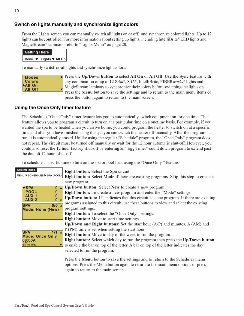
Switch on lights manually and synchronize light colors
From the Lights screen you can manually switch all lights on or off, and synchronize colored lights. Up to 12lights can be controlled. For more information about setting up lights, including IntelliBrite® LED lights andMagicStream® laminars, refer to “Lights Menu” on page 20.
To manually switch on all lights and synchronize light colors:
Press the Up/Down button to select All On or All Off. Use the Sync feature withany combination of up to 12 SAm®, SAL®, IntelliBrite, FIBERworks® lights andMagicStream laminars to synchronize their colors before switching the lights on.Press the Menu button to save the settings and to return to the main menu items orpress the button again to return to the main screen.
Using the Once Only timer feature
The Schedules “Once Only” timer feature lets you to automatically switch equipment on for one time. Thisfeature allows you to program a circuit to turn on at a particular time on a onetime basis. For example, if youwanted the spa to be heated when you arrive home, you could program the heater to switch on at a specifictime and after you have finished using the spa you can switch the heater off manually. After the program hasrun, it is automatically erased. Unlike using the regular “Schedule” program, the “Once Only” program doesnot repeat. The circuit must be turned off manually or wait for the 12 hour automatic shut-off. However, youcould also reset the 12 hour factory shut-off by entering an “Egg Timer” count down program to extend pastthe default 12 hours shut-off.
To schedule a specific time to turn on the spa or pool heat using the “Once Only “ feature:
Right button: Select the Spa circuit.Right button: Select Mode if there are existing programs. Skip this step to create anew program.Up/Down button: Select New to create a new program.Right button: To create a new program and enter the “Mode” settings.Up/Down button: 1/1 indicates that this circuit has one program. If there are existingprograms assigned to this circuit, use these buttons to view and select the existingprogram settings.Right button: To select the “Once Only” settings.Right button: Move to start time settings.Up/Down and Right buttons: Set the start hour (A/P) and minutes. A (AM) andP (PM) time is set when setting the start hour.Right button: Move to day of the week to run the program.Right button: Select which day to run the program then press the Up/Down buttonto enable the bar on top of the letter. A bar on top of the letter indicates the dayselected to run the program.
Press the Menu button to save the settings and to return to the Schedules menuoptions. Press the Menu button again to return to the main menu options or pressagain to return to the main screen.
Getting There
Menu Lights All On▲ ▲
MENU ▼ SCHEDULES SPA (POOL)
Getting There
▲
SPA 0/0Mode: None (New)
SPA 0 POOL 0 AUX 1 0 AUX 2 0
SPA 1/1Mode: Once Only08:00ASMTWTFS
_
ModesColorsAll OnAll Off
11
EasyTouch Pool and Spa Control System User’s Guide
Schedule start and stop times for equipment
You can set timers (schedules) to automatically run equipment for pool filtration or turn on or off lights. AnyEasyTouch circuit can be set to switch on and off on every or any day of the week. Up to 12 total systemprograms may be created for all circuits combined.
Program your Spa or Pool
You can use the “Schedule” feature to set the time and day(s) when to switch the filter pump on and rotate thepool/spa valves into the “Pool” or “Spa” position. The heater will automatically heat the pool or spa water upto the set point temperature as set in the “Heat” menu (see page 25). If the pool has a separate jet pump orblower controlled by AUX 1 and/or AUX 2 , these need to be scheduled separately. If you don’t have enoughor you need to conserve auxiliary relay circuits, you can program up to eight (8) “Feature Circuits.” If afeature circuit is scheduled, it must be turned on from the control panel “Feature Circuits” menu to allow theschedule to run (see page 17).
Schedules
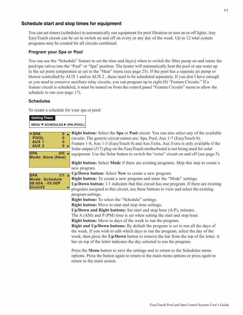
To create a schedule for your spa or pool:
Right button: Select the Spa or Pool circuit. You can also select any of the availablecircuits. The generic circuit names are: Spa, Pool, Aux 1-7 (EasyTouch 8),Feature 1-8, Aux 1-3 (EasyTouch 4) and Aux Extra. Aux Extra is only available if theSolar output (J17) plug on the EasyTouch motherboard is not being used for solarequipment. Use the Solar button to switch the “extra” circuit on and off (see page 5).
Right button: Select Mode if there are existing programs. Skip this step to create anew program.Up/Down button: Select New to create a new program.Right button: To create a new program and enter the “Mode” settings.Up/Down button: 1/1 indicates that this circuit has one program. If there are existingprograms assigned to this circuit, use these buttons to view and select the existingprogram settings.Right button: To select the “Schedule” settings.Right button: Move to start and stop time settings.Up/Down and Right buttons: Set start and stop hour (A/P), minutes.The A (AM) and P (PM) time is set when setting the start and stop hour.Right button: Move to days of the week to run the program.Right and Up/Down buttons: By default the program is set to run all the days ofthe week. If you wish to edit which days to run the program, select the day of theweek, then press the Up/Down button to remove the bar from the top of the letter. Abar on top of the letter indicates the day selected to run the program.
Press the Menu button to save the settings and to return to the Schedules menuoptions. Press the button again to return to the main menu options or press again toreturn to the main screen.
MENU ▼ SCHEDULES SPA (POOL)
Getting There
▲
SPA 0/0Mode: None (New)
SPA 0 POOL 0 AUX 1 0 AUX 2 0
SPA 1/1Mode: Schedule08:00A - 05:00Psmtwtfs
__ _ _
12
EasyTouch Pool and Spa Control System User’s Guide
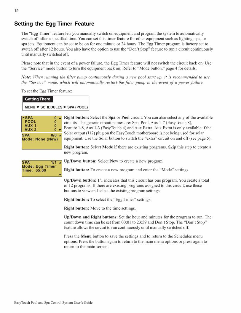
Setting the Egg Timer Feature
The “Egg Timer” feature lets you manually switch on equipment and program the system to automaticallyswitch off after a specified time. You can set this timer feature for other equipment such as lighting, spa, orspa jets. Equipment can be set to be on for one minute or 24 hours. The Egg Timer program is factory set toswitch off after 12 hours. You also have the option to use the “Don’t Stop” feature to run a circuit continuouslyuntil manually switched off.
Please note that in the event of a power failure, the Egg Timer feature will not switch the circuit back on. Usethe “Service” mode button to turn the equipment back on. Refer to “Mode button,” page 4 for details.
Note: When running the filter pump continuously during a new pool start up, it is recommended to usethe “Service” mode, which will automatically restart the filter pump in the event of a power failure.
To set the Egg Timer feature:
Right button: Select the Spa or Pool circuit. You can also select any of the availablecircuits. The generic circuit names are: Spa, Pool, Aux 1-7 (EasyTouch 8),Feature 1-8, Aux 1-3 (EasyTouch 4) and Aux Extra. Aux Extra is only available if theSolar output (J17) plug on the EasyTouch motherboard is not being used for solarequipment. Use the Solar button to switch the “extra” circuit on and off (see page 5).
Right button: Select Mode if there are existing programs. Skip this step to create anew program.
Up/Down button: Select New to create a new program.
Right button: To create a new program and enter the “Mode” settings.
Up/Down button: 1/1 indicates that this circuit has one program. You create a totalof 12 programs. If there are existing programs assigned to this circuit, use thesebuttons to view and select the existing program settings.
Right button: To select the “Egg Timer” settings.
Right button: Move to the time settings.
Up/Down and Right buttons: Set the hour and minutes for the program to run. Thecount down time can be set from 00:01 to 23:59 and Don’t Stop. The “Don’t Stop”feature allows the circuit to run continuously until manually switched off.
Press the Menu button to save the settings and to return to the Schedules menuoptions. Press the button again to return to the main menu options or press again toreturn to the main screen.
SPA 1/1Mode: Egg TimerTime: 05:00
SPA 0/0Mode: None (New)
SPA 0 POOL 0 AUX 1 0 AUX 2 0
MENU ▼ SCHEDULES SPA (POOL)
Getting There
▲

13
EasyTouch Pool and Spa Control System User’s Guide
Section 2Setting up EasyTouch
Setting up the System for the First Time
Use the following steps if you are setting up the EasyTouch system for the first time.Note: The following setup steps assume that the EasyTouch Load Center is installed at the equipmentpad and ready for operation. For EasyTouch Load Center installation instructions, refer to theEasyTouch 8 and 4 Load Center Installation Guide (P/N 520583).The recommended first time installation steps for the EasyTouch system are:
1. Set the system date and time (page 31)Set the current date and time.
2. Assign circuit names (pages 41)Assign the generic default circuit names for output auxiliary equipment. Rename (if necessary) and assigncircuit names to the auxiliary (AUX 1, AUX 2) connections. Note the factory set auxiliary names correspondto the plug-in location of the relay on the EasyTouch motherboard. You can assign circuit names from theavailable of circuit names. There are nearly 100 circuit names available (see page 38 for the complete list).
3. Create custom names for auxiliary circuits (page 45)If you cannot find a circuit name that fits your application you can create up to 10 additional customizednames that can be created before assigning circuit names.
4. Assign a “Circuit Function” to a “Circuit Name” (Page 43)Assign “Circuit Functions” to the auxiliary circuit names you created in Step 3 above. From the CircuitFunction” menu (page 39), you can assign special logic to a circuit by selecting one of the available circuitfunctions. For the complete list of preset Circuit Functions. If an auxiliary circuit (AUX) is assignedGENERIC (simple ON/OFF when the button is pushed) then nothing needs to be done.
5. Create “Feature Circuits” to conserve relays (page 17)If you need to conserve physical auxiliary EasyTouch load center relays, there are eight (8) Feature Circuitsavailable that you can assign to circuit functions. Feature Circuits are manually turned on or off from thecontrol panel “Feature Circuits” menu.
6. Configure valve actuators (controlled by AUX circuit) (page 45)The EasyTouch system can drive two auxiliary valve actuators for applications such as solar heating andwater features. Assign which circuits that will activate valves A and B. Auxiliary valve actuators can becontrolled by any AUX circuit. Valve A is automatically assigned to solar if “Solar” is enabled in the “Solar”menu. Tip: Use a “Feature Circuit” to control a valve actuator (see page 17).
7. Set up optional equipment, solar, two-speed pump (page 46)Set up additional equipment such as solar, 2-speed pump, and optional equipment if required. Set up the controlpanel to operate with the optional IntelliChlor chlorine generator (see page 37) and IntelliChem (see page 38).To configure EasyTouch for special equipment:
• Is solar heating available? Is solar being used for a heat pump?
• What circuits will turn 2-Speed pumps to High Speed?
• Is there a heat pump (UltraTemp) being used?
• Is there an IntelliChlor installed?
• Is there an IntelliChem installed?
• Cool-down cycle for the heater - Lets you set circuits that switch the filter pump to high speed.
• Do you want to delay turning off the filter pump for 10 minutes when the heater is turned off?
• Do you want the spa to heat whenever the Spa button is pressed?

14
EasyTouch Pool and Spa Control System User’s Guide
8. Configure the heater system options (page 25)Set the type of heat source being used (Heater, Solar, Solar Preferred). Enable heat pump (UltraTemp) forheating/cooling if installed.
9. Configure the iS4, iS10, SpaCommand spa-side remote, QuickTouch wireless remote buttons (page 49)
Assign circuits to the iS4, iS10, SpaCommand or QuickTouch remote buttons. Once you have checked that allbuttons operate properly, place labels on remote buttons. iS4, iS10 and SpaCommand buttons can be assignedto increase or decrease the IntelliFlo® VS, VF or VSF+SVRS pump speed using specific RPM or GPMincrements.
10. Set the delays feature (page 47)Enable the one time “delay” feature for the heater, 2-speed pump, and automatic pool cleaner.
11. Schedule on/off times for circuit (page 27 - 30)Set times for automatic circuit activation. Up to 12 total programs can be created for all circuits combined.One circuit can have up to a maximum of 9 programs (9/9), which leaves 3 programs that can be used by onecircuit or three separate circuits for a total of 12 programs. All user created programs are active all the time;so check that there are not conflicting automated times.
12. Setup lighting and MagicStream laminars settings (page 23)From the lighting menu you can control and synchronized your pool/spa, MagicStream laminars and yardlighting.
EasyTouch MenusMAIN SCREEN
LIGHTS
HEAT POOL TEMP/SRC TEMP (40˚ F - 106˚ F) OR (4˚ C - 41˚ C)HEAT (OFF/HEATER/SOLAR/SOLAR PRF) - SOLAR/SOLAR PRF MUST BE ENABLED IN "SOLAR" MENU TO DISPLAY.
SPA TEMP/SRC TEMP (40˚ F - 106˚ F) OR (4˚ C - 41˚ C)HEAT (OFF/HEATER/SOLAR/SOLAR PRF) - "SOLAR/SOLAR PRF" MUST BE ENABLED IN "SOLAR" MENU TO DISPLAY.
DELAY CANCEL
MODE: SCHEDULE08:00A -- 05:00P (12:00 AM - 11:59 PM -12 HOURS)S M T W T F S (DAYS OF THE WEEK)
SCHEDULES SPA 0
AUX 2 0
AUX 4 0
AUX 3 0 MODE: EGG TIMER TIME: 12:00 (00:00 - 23:59) / DON'T STOP
(DELAYED CANCELLED) PRESS RIGHT BUTTON TO ACTIVATE
POOL 0
AUX 1 0
AUX 5 0
AUX 6 0
AUX 7 0
EASYTOUCH 4
EASYTOUCH 8MODE: ONCE ONLY08:00A (12:00 AM - 11:59 PM -12 HOURS)S M T W T F S (SELECT DAY OF THE WEEK TO RUN PROGRAM)
MODE: NEW / DELETE / NONE
HI-TEMP (SPA) / LO-TEMP (POOL) FOR SINGLE BODY SYSTEM (SEE SETTINGS MENU: CIRCUIT NAMES)
FEATURE 1-8 0
AUX EXTRA: AUXILIARY OUTPUT (USE DOWN ARROW BUTTON TO SWITCH ON/OFF). ONLY AVAILABLE IF SOLAR PLUG (J17) IF NOT BEING USED FOR SOLAR EQUIPMENT.
MODES [6 LIGHT SHOWS, HOLD, RECALL, COLOR SWIM, COLOR SET]COLORS [5 FIXED COLORS, HOLD, RECALL, COLOR SWIM, COLOR SET]ALL ON (SWITCH ALL LIGHTS ON)ALL OFF (SWITCH ALL LIGHTS OFF)SYNC (SYNCHRONIZE COLORED LIGHTS)MAGICSTREAM [TOGGLE THUMPER, HOLD, RESET, CHANGE MODE]CONFIG (SETUP EIGHT LIGHT POSITIONS)
FEATURE CIR FEATURE 1-8 [OFF]
AUX EXTRA 0
FEATURE 1 - 8
MANUALLY TURN A FEATURE CIRCUIT ON/OFF.USE FEATURE CIRCUITS TO CONTROL PUMP SPEEDS AND VALVES.
Continue on next page.

15
EasyTouch Pool and Spa Control System User’s Guide
EasyTouch Menus (Continued)SETTINGS
INTELLICHLOR INTELLICHLOR 1/2 - ENABLE (YES/NO), POOL MODE: 0 - 100 % (50% default) SPA MODE: 0% (2% default)INTELLICHLOR 2/2 - SUPER CHLR (ON/OFF), RUN HOURS (0 -72) (OPTIONAL)
CIRCUIT NAMES CIRCUIT NAMES (1/18) - [SPA, POOL, AUX 1-7 (ET8), AUX 1-3 (ET4), FEATURE 1-8, AUX EXTRA
CIRCUIT FUNC. CIRCUIT: (SPA [MASTER SPA], POOL [MASTER POOL], AUX 1-7 (AUX 1-3), FEATURE 1-8, AUX EXTRA - FUNCTIONS: GENERIC, MASTER SPA, MASTER POOL,
FREEZE: NO/YES
CUSTOM NAMES CSTM NAME 1/10 (ASSIGN UP TO 10 CUSTOM NAMES) [USERNAME-01...10] (UP TO 11 ALPHANUMERIC CHARACTERS)
2-SPEED PUMPCIRCUIT (NONE, SPA, POOL, AUX 1 - 3 (ET 4) - SPA, POOL, AUX 1 - 7 (ET 8), FEATURE 1-8, AUX EXTRA, SOLAR, HEATER, POOL HEATER, SPA HEATER, FREEZE) 2-SPEED PMP 1/4 (ASSIGN UP TO 4 CIRCUITS)
SOLAR
DELAYS COOL DOWN (YES/NO) - VALVES (YES/NO)
SOLAR 1/2 - ENABLE (YES/NO) - HEAT PUMP (YES/NO) - SOLAR 2/3 - FREEZE, NIGHT COOL (YES/NO)SOLAR 3/3 (TEMPREATURE DIFFERENCE) - START (3˚-9˚ (6˚ default)) - RUN (2˚-5˚ (3˚ default))
VALVES
CLOCK
F˚ / C˚
iS4
FAHRENHEIT / CELCIUS
CIRCUIT - (NONE, SPA, POOL, AUX 1 - 7 (ET 8), AUX 1 - 3 (ET 4), FEATURE 1-8, AUX EXTRA, HEAT BOOST, HEAT ENABLE, PUMP INCRS, PUMP DECRS) ASSIGN CIRCUITS 1/4
DATE & TIME 1/2 - (MONTH/DAY/YEAR) - (DAY/HOUR/MINUTES/AM/PM) DATE & TIMER 2/2 - DAYLIGHT SAVING: (AUTO/MANUAL)CLOCK ADJUST 00:00 (0 TO 300) - (-300 TO -5) IN 5 SCEOND INCREMENTS
A: [NONE, SPA, POOL, AUX 1 - 3 (ET 4) - SPA, POOL, AUX 1 - 7 (ET 8), FEATURE 1-8, AUX EXTRA, HEATER] - (USED SOLAR IF SOLAR IS ENABLED)B: [NONE, SPA, POOL, AUX 1 - 3 (ET 4) - SPA, POOL, AUX 1 - 7 (ET 8), FEATURE 1-8, AUX EXTRA, HEATER]
MSTR CLEANER, LIGHT, SAM LIGHT, SAL LIGHT, PHOTON GENERATOR, COLOR WHEEL, SPILLWAY, FLOOR CLEANER, INTELLIBRITE, MAGICSTREAM
DIAGNOSTICS SOFTWARE REV (REVISION LEVEL FOR THE OUTDOOR AND INDOOR CONTROL PANEL)BOOTLOADER REV (REVISION LEVEL FOR THE OUTDOOR AND INDOOR CONTROL PANEL)SELF TEST (STATUS: TESTING (FOLLOW ON-SCREEN PROMPTS TO TEST LCD AND BUTTONS) - CODE: 0 - SEE "TROUBLESHOOTING" SECTION FOR ERROR CODES)
WATER TEMP (FAHRENHEIT/CELCIUS - STATUS DISPLAY ONLY)SOLAR TEMP (FAHRENHEIT/CELCIUS - STATUS DISPLAY ONLY) - (DISPLAYS IF SOLAR IS ENABLED IN HEAT MENU)AIR TEMP (FAHRENHEIT/CELCIUS - STATUS DISPLAY ONLY)DISP OP CODES - DISPLAY? NO/YES (DISPLAYS TRANSMIT/RECEIVE PACKETS NUMBERS ON SCREEN)
SPA SIDE [OFF/ON] ENABLE/DISABLE IS4 SPA-SIDE REMOTE
CIR NAMES [ON/OFF] VIEW DEFAULT CIRCUIT NAMES BEFORE MODIFICATION.
CHLORINATOR SALT LEVEL: DISPLAYS CURRENT SALT LEVEL (XXXX) PPMSTATUS: OK - NO ERRORS (SUPER CHLORINATE, COM LINK ERROR, CHECK FLOW / PCB, LOW SALT, VERY LOW SALT, HIGH CURRENT, CLEAN CELL!!, LOW VOLTAGE)
RESET SYSTEM (REINITIALIZE INDOOR CONTROL PANEL - USE RIGHT BUTTON)FLASH UPDATE (USED FOR FIRMWARE UPDATES VIA PC - PRESS MENU TO ABORT)
INTELLIFLO(OPTIONAL)
PUMP #1 - PUMP TYPE [VF, VS, VSF, NONE] - VF: FILTR. CIRCUIT, FLOW (GPM), FILTERING, PRIMING, BACKWASH, VACUUM, STATUS PUMP #2 - PUMP TYPE [VF, VS, VSF, NONE] - VS: SPEEDS (RPM), PRIMING, STATUS - VSF: FLOW/SPEEDS (RPM/GPM), STATUS
HEAT PUMP COM SETTINGS: ENABLE, DISABLE (NO/YES) - [HEATING, COOLING] - STATUS(OPTIONAL)
10 BUTN SPA SDASSIGN CIRCUITS 1/5 (NONE, SPA, POOL, AUX 1 - AUX 7 (ET 8), AUX 1 - AUX 3 (ET 4), FEATURE 1-8, AUX EXTRA, HEAT BOOST, HEAT ENABLE, PUMP INCRS, PUMP DECRS)) TOP ROW (1/5), BOTTOM ROW (1/5)
QUICK TOUCH ASSIGN QT4 1/4 (ASSIGN UP TO 4 CIRCUITS)CIRCUIT - (NONE, SPA, POOL, AUX 1 - AUX 7 (ET 8), AUX 1 - AUX 3 (ET 4), FEATURE 1-8, AUX EXTRA, HEAT BOOST, HEAT ENABLE)
ERASE EEPROM ERASE ALL (YES /NO) - ARE YOU SURE? (YES/NO)
CALIBRATION WATER (FAHRENHEIT/CELCIUS) - AIR (FAHRENHEIT/CELCIUS) - SOLAR (FAHRENHEIT/CELCIUS) - SOLAR MUST BE ENABLED IN "HEAT" MENU TO DISPLAY
SWITCH MANUAL HEAT ON OR OFF WHEN SPA IS MANUALLY SWITCHED ON (USE RIGHT BUTTON SELECT ON/OFF)MAN HEAT [OFF/ON]
SET PASSWORD SET PASSWORD: {XXXX} 4 DIGITS - ENABLE / DISABLE [NO/YES]
WIRELESS ADDR SET AN ADDRESS FOR EASYTOUCH WIRELESS CONTROL PANEL
10B PUMP CTRL ASSIGN IS10 and IS4 PUMP CONTROLS [PUMP NUMBER 1/2, STEP RPM: 10-250, GPM: 1-10]
INTELLICHEM PH/OPR Values (pH VAL, SET - OPR VAL, SET) - Status (pH/OPR level) - Saturation Index (CH,TDS,TA,SI)(OPTIONAL)

16
EasyTouch Pool and Spa Control System User’s Guide
EasyTouch Menus
From the EasyTouch control panel menus you can schedule everyday pool/spa, heating, filtration and cleaning.Lights and laminars can also be scheduled to switch on and off at specific times. The “Settings” and“Schedule” menus are typically used most often for daily spa and pool operations. The “Settings” menu is usedby the pool installer to setup installed equipment which is connected to each output relay (filter pump, auxiliaryrelays, heater, valves, lights, etc.). For EasyTouch equipment installation instructions, see the EasyTouchInstallation Guide (P/N 520584).
Main ScreenThe EasyTouch main screen displays the current mode of operation(AUTO/SERVICE/TIMEOUT), heat source being used, spa (or pool) actual watertemperature (95° F), current heater set point temperature (100° F) and the currentambient air temperature (air sensor). Degree units can be displayed in eitherFahrenheit (default) or Celsius (see page 48). If the second display line is blank andthe heat source is not displayed, there is no spa or pool function currently active. Themain screen is automatically displayed if there is no control panel menu activity forfive minutes. If there is an IntelliChlor salt chlorinator generator being used, pool andspa sanitizer settings, and salt levels can be viewed in the Diagnostics, “Chlorinator,”settings (see page 37).
Main Screen DescriptionAUTO: EasyTouch is in normal (automatic) operating mode. For information about “Service” and “Timeout”operating modes, see page 4.
HEATER: The selected heat source as selected in the “Heat” menu (see page 25). The heat options are:
• OFF - No heating even though pump and other circuits may be operating.• HEATER - Gas heater only.• SOLAR ONLY - Solar heating system to be the only heat source. In order to display “Solar Pref.” on
the main screen, you must first enable solar in the “Solar” menu (see page 46).• SOLAR PREF. - (Solar Preferred) - For when solar and gas heating are combined, and you want to
use solar heating only when it is most effective. In order to display “Solar Pref.” on the main screen,you must first enable solar in the “Solar” menu.
SPA: “SPA” is displayed after the Valves (V) button is pressed to set in “spa” mode then the Filter (F)button is pressed to switch the filter pump on, rotate the valve actuator (to isolate spa water from pool water),and switch the heater on (if enabled in the “Heat” menu). Pressing the Valves (V) button alternates between“Pool” and “Spa” mode. The temperature unit displayed on the left side is the actual water temperature (95°F) and the set point temperature (100° F) as set in the “Heat” menu is displayed on the right side. If thisdisplay line is blank, it indicates no spa or pool function is currently active. For Hi-Temp controls (EasyTouchsingle body system), see page 41.
POOL: “POOL” is displayed after the Filter (F) button is pressed to switch the filter pump on, rotate thevalve actuator to isolate the pool water from the spa water, and switch the heater on (if enabled in the “Heat”menu). Pressing the Valves (V) button alternates between “Pool” and “Spa” mode. The temperature unitdisplayed on the left side is the actual water temperature (95° F) and the set point temperature (100° F) as setin the “Heat” menu is displayed on the right side. If this display line is blank, it indicates no spa or pool functionis currently active. For Lo-Temp controls (EasyTouch single body system), see page 41.
AIR: Displays the actual outside ambient air temperature (70° F) as recorded by the air sensor located nearthe EasyTouch load center.
DAY and TIME: The current system day and time (AM/PM). See the “Clock” menu to set the system day andtime (page 46).
AUTO HEATERSPA 95°F / 100°FAIR 70°F MON 09:30 AM
AUTO
AIR 70°F MON 11:30 AM
AUTO HEATERPOOL 85°F / 95°FAIR 70°F MON 10:30 AM

17
EasyTouch Pool and Spa Control System User’s Guide
Feature Circuits Menu
There are eight (8) “Feature Circuits” that can be used to control IntelliFlo pump speeds or valves actuatorsfor a spa spillway. Unlike an auxiliary relay circuit, a “Feature” circuit does not connect directly to a relay.“Feature” are turned on and off from the control panel “Feature” circuit menu.
Feature Circuits
To switch a feature circuit ON or OFF:
Right button: Select the feature circuit to turn ON or OFF..Up/Down buttons: Choose assigned feature circuit: FEATURE 1 - 8.Right button: Switch the selected feature circuits ON or OFF.
When finished, press the Menu button twice to return to the main screen.
Getting There
Menu F. Circuits▲
F. CircuitsLightsHeatDelay Cancel
FEATURE 1 [ON]FEATURE 2 [OFF]FEATURE 3 [OFF]FEATURE 4 [OFF]
FEATURE 5 [ON]FEATURE 6 [OFF]FEATURE 7 [OFF]FEATURE 8 [OFF]

18
EasyTouch Pool and Spa Control System User’s Guide
Lights Menu
From the Lights screen you can manually switch all lights on or off, and synchronize colored lights. Up toeight (8) lights (EasyTouch 8) or 4 lights (EasyTouch 4) can be independently controlled from the Lightsscreen. Each light requires a separate auxiliary relay circuit. Up to four lights can be assigned on eachauxiliary circuit. A circuit name must be assigned to the AUX relay circuits which controls the light. Verify thatIntelliBrite, SAm and/or SAL, and/or FIBERworks have been selected in Circuit Function. If FIBERworkslighting is being used, it also has to be set up as a Photon Generator® light source (PHOTON GENERATOR)for the circuit controlling the light bulb, and COLOR WHEEL for the circuit controlling the color wheel. Formore information about setting up lights, see “Settings Menu: Circuit Function,” on page 43.
The Color Swim and Color Set Lighting Features
The Color Swim and Color Set lighting features is selected from the LIGHTS > MODES and (COLORS)menu. At least two (2) Pentair Water Pool and Spa®, IntelliBrite®, SAm®, SAL®, and/or FIBERworks® lightingsystems are required to use the lighting features.
• Color Swim - Select the Color Swim feature in the MODES and COLORS menus to start lights totransition through colors in sequence to give the appearance of colors dancing through the water. Youcan adjust the delay of each light to make the colors move at different speeds using the LIGHTS >CONFIG option. This lighting feature requires a separate relay for each light. To switch off the ColorSwim feature, select the AUX button assigned to the light circuit or select ALL OFF in the Lightsmenu.
• Color Set - Select the Color Set feature in the MODES and COLORS menus to switch the light onusing specific color as selected in the COLORS menu. This feature requires a separate relay foreach light. To switch off the Color Swim feature, select the AUX button assigned to the light circuitor select ALL OFF in the Lights menu.
• Configure - Select “Configure” to setup the positions of the lights the pool. Up to eight (8) lights canbe assigned a position. For more information see page 22.
• Sync - Select the Sync feature in the LIGHTS menu to switch on all IntelliBrite, SAm, SAL, orFIBERworks color changing lights and synchronize their colors.
• Smart Start (SS: Yes/No) - Select Smart Start in the Schedules menu (see page 27). The Smart Startfeature automatically starts changing colors when the lights are programmed to switch on. SmartStart is used when Color Swim and IntelliBrite show modes are being used.
Getting There
MENU LIGHTS LIGHTS▲▲
All OnAll OffSyncConfigure
1- [NONE ]2- [NONE ]3- [NONE ]4- [NONE ]
1- [AUX 1 ]2- [LT.GREEN ]3- [1ST POSITION ]4. [DELAY 5 SECS]
ModesColorsAll OnAll Off
HoldRecallColor SwimColor Set
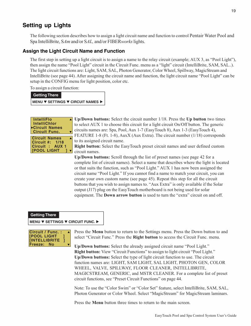
19
EasyTouch Pool and Spa Control System User’s Guide
Setting up Lights
The following section describes how to assign a light circuit name and function to control Pentair Water Pool andSpa IntelliBrite, SAm and/or SAL, and/or FIBERworks lights.
Assign the Light Circuit Name and Function
The first step in setting up a light circuit is to assign a name to the relay circuit (example; AUX 3, as “Pool Light”),then assign the name “Pool Light” circuit in the Circuit Func. menu as a “light” circuit (IntelliBrite, SAM, SAL..).The light circuit functions are: Light, SAM, SAL, Photon Generator, Color Wheel, Spillway, MagicStream andIntelliBrite (see page 44). After assigning the circuit name and function, the light circuit name “Pool Light” can besetup in the CONFIG menu for light position, color etc.
To assign a circuit function:
Up/Down buttons: Select the circuit number 1/18. Press the Up button two timesto select AUX 1 to choose this circuit for a light circuit On/Off button. The genericcircuits names are: Spa, Pool, Aux 1-7 (EasyTouch 8), Aux 1-3 (EasyTouch 4),FEATURE 1-8 (Ft. 1-8), AuxX (Aux Extra). The circuit number (1/18) correspondsto its assigned circuit name.Right button: Select the EasyTouch preset circuit names and user defined customcircuit names.Up/Down buttons: Scroll through the list of preset names (see page 42 for acomplete list of circuit names). Select a name that describes where the light is locatedor that suits the function, such as “Pool Light.” AUX 1 has now been assigned thecircuit name “Pool Light.” If you cannot find a name to match your circuit, you cancreate your own custom name (see page 45). Repeat this step for all the circuitbuttons that you wish to assign names to. “Aux Extra” is only available if the Solaroutput (J17) plug on the EasyTouch motherboard is not being used for solarequipment. The Down arrow button is used to turn the “extra” circuit on and off.
Press the Menu button to return to the Settings menu. Press the Down button to andselect “Circuit Func.” Press the Right button to access the Circuit Func. menu.
Up/Down buttons: Select the already assigned circuit name “Pool Light.”Right button: View “Circuit Functions” to assign to light circuit “Pool Light.”Up/Down buttons: Select the type of light circuit function to use. The circuitfunction names are: LIGHT, SAM LIGHT, SAL LIGHT, PHOTON GEN, COLORWHEEL, VALVE, SPILLWAY, FLOOR CLEANER, INITELLIBRITE,MAGICSTREAM, GENERIC, and MSTR CLEANER. For a complete list of presetcircuit functions, see “Preset Circuit Functions” on page 44.
Note: To use the “Color Swim” or “Color Set” feature, select IntelliBrite, SAM, SAL,Photon Generator or Color Wheel. Select “MagicStream” for MagicStream laminars.
Press the Menu button three times to return to the main screen.
Circuit NamesCircuit #: 1/18Circuit : AUX 1[POOL LIGHT ]
Circuit / Func. :[POOL LIGHT ][INTELLIBRITE ]Freeze: No
IntelliFlo IntelliChlor Circuit Names Circuit Func.
MENU ▼ SETTINGS ▼ CIRCUIT FUNC. ▲
Getting There
MENU ▼ SETTINGS ▼ CIRCUIT NAMES ▲
Getting There

20
EasyTouch Pool and Spa Control System User’s Guide
Setting up lights
From the Lights screen you can manually switch all lights on or off, synchronize colored lights, and activatecolor light shows. Up to eight (EasyTouch 8) or four (EasyTouch 4) light circuits can be configured from the“Config” light menu. Each light must have its own relay and separate circuit.
Setting up IntelliBrite Light Circuits
Before configuring the lights, be sure the auxiliary (AUX) circuits that control the IntelliBrite lights have beenassigned as an “IntelliBrite” light. For more information about “Circuit Functions” (page 43) and “CircuitNames,” (page 41).
Lights Menu
To access the Lights menu screen, press Menu > Lights. The Lights menu settings are: MODES, COLORS,ALL ON, ALL OFF, SYNC, MAGICSTREAM, CONFIG:
Modes (IntelliBrite Color light shows, Color Swim, Color Set)
To access the Modes menu, press Menu > Lights > Modes. There are six pre-programmed color lightshows to choose from. From the “Modes” screen you can select various preset show color lighting effects,such as “American mode” and “Sunset mode”, “Color Swim” or “Color Set.” Using the “Hold” and “Recall”feature (see page 21) you can also capture and save a unique color light show effect to recall at a later time.
The IntelliBrite color “Mode” settings light shows are:
• Party: Rapid color changing building the energy and excitement
• Romance: Slow color transitions creating a mesmerizing and calming effect
• Caribbean: Transitions between a variety of blues and greens
• American: Patriotic red, white and blue transition
• Sunset: Dramatic transitions of orange, red and magenta tones
• Royalty: Richer, deeper, color tones
IntelliBrite Light: If the IntelliBrite light was not previously on, after selecting a color show mode, noillumination will occur for up to ten (10) seconds (depending on the selection), then a white light willmomentarily illuminate, followed by the color show mode selection. If the light was previously on,selecting the a color show mode button will momentarily illuminate the previously selected color beforechanging to the selected color show.
Modes (Color Swim)
The Color Swim feature cycles through white, magenta, blue and green colors. Using IntelliBrite lights, ColorSwim emulates the Pentair Water Pool and Spa SAM and SAL Color Swim feature.
IntelliBrite Light Color Swim/Color Set: If the light was not previously on, after selecting Color Swim,no illumination will occur for approximately six (6) seconds followed by the selection. If the light waspreviously on, after selecting the Color Swim feature, the previously selected color will momentarilyilluminate, no illumination will occur for approximately six (6) seconds followed by the selection.
Getting There
MENU LIGHTS LIGHTS▲▲

21
EasyTouch Pool and Spa Control System User’s Guide
Setting up lights (Continued)
Modes (Color Set)
The “Color Set” feature allows any combination of up to eight (EasyTouch 8) or four (EasyTouch 4)IntelliBrite lights, and SAm, SAL and or Fiberworks lighting to be preset to specific colors. Fixed light colorsare selected and activated from the Colors screen.
IntelliBrite Light: If the light was not previously on, after selecting the fixed colored light, noillumination will occur for approximately six (6) seconds followed by the selection. If the light waspreviously on, after selecting the colored light, the previously selected color will momentarily illuminate,no illumination will occur for approximately six (6) seconds followed by the selection.
ColorsChoose any one of the five fixed colors to create a spectacular underwater lighting effect. The fixed colorsare: Blue, Green, Red, White and Magenta. You can switch each fixed colored light on or off from theColors screen.
IntelliBrite Light: If the light was not previously on, after selecting a fixed colored light, no illuminationwill occur for up to ten (10) seconds (depending on the selection), then a white light will momentarilyilluminate, followed by the color selection. If the light was previously on, selecting the a color buttonwill momentarily illuminate the previously selected color before changing to the selected color.
To select a fixed color press: Menu > Lights > Modes > Colors:
Up/Down buttons: Choose a color for the light.Right button: Switch the selected colored light ON. To switch the light off, go tothe main Lights menu and select All Off, or press the AUX button assigned to thelight. The AUX button will also switch the light on.Press the Menu button three times to return main menu.
Hold/RecallSelect Hold and Recall from the “Modes” or “Color” screen to capture and save a unique color effect andrecall it at a later time. For example, while a light show (Romance Mode) is active, select “Hold” to save theexact colors that are being displayed, then later, to recall the exact color effect, select “Recall.”Note: After selecting Hold or Recall, no illumination will occur for up to 10 seconds, then a white lightwill momentarily illuminate, followed by the saved color.
All On / All Off (Lights Menu)Select All On or All Off from the Lights screen to manually switch all lights on or off, including anyMagicStream laminar circuits. Press the control panel auxiliary button (AuxX) assigned to a light circuit willalso switch a light on or off.
SyncSelect Sync from the “Lights” screen to synchronize colors for all IntelliBrite, SAm, SAL and FIBERworkscolor changing lights.
WARNING - IntelliBrite Lights: During the off/on switching process,before the selected color is displayed, no illumination will occur. Thisoperating mode is normal during the switching process. During this periodthe pool and spa will be dark and precautions should be taken to avoidunforeseen accidents. Failure to observe this warning may result inserious injury or death to pool and spa users.
Blue Green Red White
Green Red White Magenta
Magenta
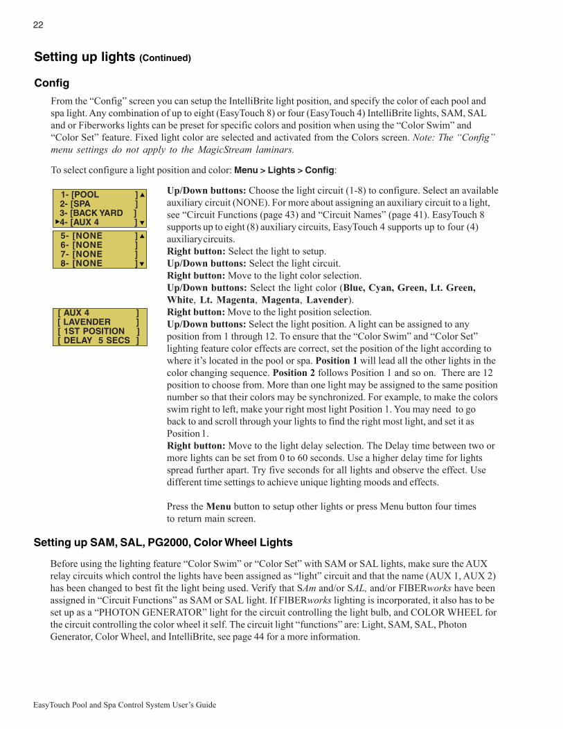
22
EasyTouch Pool and Spa Control System User’s Guide
Setting up lights (Continued)
Config
From the “Config” screen you can setup the IntelliBrite light position, and specify the color of each pool andspa light. Any combination of up to eight (EasyTouch 8) or four (EasyTouch 4) IntelliBrite lights, SAM, SALand or Fiberworks lights can be preset for specific colors and position when using the “Color Swim” and“Color Set” feature. Fixed light color are selected and activated from the Colors screen. Note: The “Config”menu settings do not apply to the MagicStream laminars.
To select configure a light position and color: Menu > Lights > Config:
Up/Down buttons: Choose the light circuit (1-8) to configure. Select an availableauxiliary circuit (NONE). For more about assigning an auxiliary circuit to a light,see “Circuit Functions (page 43) and “Circuit Names” (page 41). EasyTouch 8supports up to eight (8) auxiliary circuits, EasyTouch 4 supports up to four (4)auxiliary circuits.Right button: Select the light to setup.Up/Down buttons: Select the light circuit.Right button: Move to the light color selection.Up/Down buttons: Select the light color (Blue, Cyan, Green, Lt. Green,White, Lt. Magenta, Magenta, Lavender).Right button: Move to the light position selection.Up/Down buttons: Select the light position. A light can be assigned to anyposition from 1 through 12. To ensure that the “Color Swim” and “Color Set”lighting feature color effects are correct, set the position of the light according towhere it’s located in the pool or spa. Position 1 will lead all the other lights in thecolor changing sequence. Position 2 follows Position 1 and so on. There are 12position to choose from. More than one light may be assigned to the same positionnumber so that their colors may be synchronized. For example, to make the colorsswim right to left, make your right most light Position 1. You may need to goback to and scroll through your lights to find the right most light, and set it asPosition 1.Right button: Move to the light delay selection. The Delay time between two ormore lights can be set from 0 to 60 seconds. Use a higher delay time for lightsspread further apart. Try five seconds for all lights and observe the effect. Usedifferent time settings to achieve unique lighting moods and effects.
Press the Menu button to setup other lights or press Menu button four timesto return main screen.
Setting up SAM, SAL, PG2000, Color Wheel Lights
Before using the lighting feature “Color Swim” or “Color Set” with SAM or SAL lights, make sure the AUXrelay circuits which control the lights have been assigned as “light” circuit and that the name (AUX 1, AUX 2)has been changed to best fit the light being used. Verify that SAm and/or SAL, and/or FIBERworks have beenassigned in “Circuit Functions” as SAM or SAL light. If FIBERworks lighting is incorporated, it also has to beset up as a “PHOTON GENERATOR” light for the circuit controlling the light bulb, and COLOR WHEEL forthe circuit controlling the color wheel it self. The circuit light “functions” are: Light, SAM, SAL, PhotonGenerator, Color Wheel, and IntelliBrite, see page 44 for a more information.
1- [POOL ] 2- [SPA ] 3- [BACK YARD ] 4- [AUX 4 ]
5- [NONE ] 6- [NONE ] 7- [NONE ] 8- [NONE ]
[ AUX 4 ] [ LAVENDER ] [ 1ST POSITION ] [ DELAY 5 SECS ]
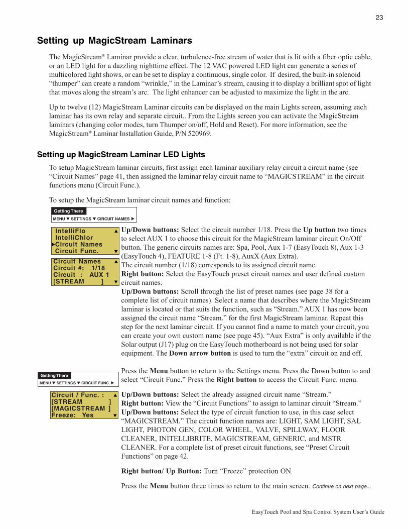
23
EasyTouch Pool and Spa Control System User’s Guide
Setting up MagicStream Laminars
The MagicStream® Laminar provide a clear, turbulence-free stream of water that is lit with a fiber optic cable,or an LED light for a dazzling nighttime effect. The 12 VAC powered LED light can generate a series ofmulticolored light shows, or can be set to display a continuous, single color. If desired, the built-in solenoid“thumper” can create a random “wrinkle,” in the Laminar’s stream, causing it to display a brilliant spot of lightthat moves along the stream’s arc. The light enhancer can be adjusted to maximize the light in the arc.
Up to twelve (12) MagicStream Laminar circuits can be displayed on the main Lights screen, assuming eachlaminar has its own relay and separate circuit.. From the Lights screen you can activate the MagicStreamlaminars (changing color modes, turn Thumper on/off, Hold and Reset). For more information, see theMagicStream® Laminar Installation Guide, P/N 520969.
Setting up MagicStream Laminar LED Lights
To setup MagicStream laminar circuits, first assign each laminar auxiliary relay circuit a circuit name (see“Circuit Names” page 41, then assigned the laminar relay circuit name to “MAGICSTREAM” in the circuitfunctions menu (Circuit Func.).
To setup the MagicStream laminar circuit names and function:
Up/Down buttons: Select the circuit number 1/18. Press the Up button two timesto select AUX 1 to choose this circuit for the MagicStream laminar circuit On/Offbutton. The generic circuits names are: Spa, Pool, Aux 1-7 (EasyTouch 8), Aux 1-3(EasyTouch 4), FEATURE 1-8 (Ft. 1-8), AuxX (Aux Extra).The circuit number (1/18) corresponds to its assigned circuit name.Right button: Select the EasyTouch preset circuit names and user defined customcircuit names.Up/Down buttons: Scroll through the list of preset names (see page 38 for acomplete list of circuit names). Select a name that describes where the MagicStreamlaminar is located or that suits the function, such as “Stream.” AUX 1 has now beenassigned the circuit name “Stream.” for the first MagicStream laminar. Repeat thisstep for the next laminar circuit. If you cannot find a name to match your circuit, youcan create your own custom name (see page 45). “Aux Extra” is only available if theSolar output (J17) plug on the EasyTouch motherboard is not being used for solarequipment. The Down arrow button is used to turn the “extra” circuit on and off.
Press the Menu button to return to the Settings menu. Press the Down button to andselect “Circuit Func.” Press the Right button to access the Circuit Func. menu.
Up/Down buttons: Select the already assigned circuit name “Stream.”Right button: View the “Circuit Functions” to assign to laminar circuit “Stream.”Up/Down buttons: Select the type of circuit function to use, in this case select“MAGICSTREAM.” The circuit function names are: LIGHT, SAM LIGHT, SALLIGHT, PHOTON GEN, COLOR WHEEL, VALVE, SPILLWAY, FLOORCLEANER, INITELLIBRITE, MAGICSTREAM, GENERIC, and MSTRCLEANER. For a complete list of preset circuit functions, see “Preset CircuitFunctions” on page 42.
Right button/ Up Button: Turn “Freeze” protection ON.
Press the Menu button three times to return to the main screen. Continue on next page...
Circuit NamesCircuit #: 1/18Circuit : AUX 1[STREAM ]
Circuit / Func. :[STREAM ][MAGICSTREAM ]Freeze: Yes
IntelliFlo IntelliChlor Circuit Names Circuit Func.
MENU ▼ SETTINGS ▼ CIRCUIT FUNC. ▲
Getting There
MENU ▼ SETTINGS ▼ CIRCUIT NAMES ▲
Getting There

24
EasyTouch Pool and Spa Control System User’s Guide
Using the MagicStream Laminar Features
The MagicStream laminar features are displayed in the MagicStream menu. Each time a MagicStreamlaminar feature is activated, it resumes with the same features in operation as when last switched off. TheMagicStream features are as follows:
Toggle Thumper - Pressing this button creates a "wrinkle" in the laminar stream, producing a brilliant spotof light in the laminar arc.
Hold - Select Hold to capture the current color effect while colors are changing. The colors will stopchanging. Selecting Hold again will resume the color changing mode.
Reset - Pressing this button reverts to the Random color changing mode with the Thumper ON.
Change Mode - Pressing this button (each successive OFF/ON combination) will cycle through Sync,Random and Party. Color changing mode - The color of the light changes automatically, according to onethe following three programs:
Sync - Colors will change at ten second intervals. In this mode, multiple laminars will synchronizecolors together. Note: To sync multiple laminars (two or more AUX circuits), be sure to define the“MagicStream” circuits in the “Circuit Functions” menu.
Random - Colors will change at ten (10) second intervals in a random sequence. In this mode,multiple laminars will NOT synchronize colors together.
Party - Colors will change randomly and slowly at first, then speed up, until the sequence endswith quick flashes and strobes. The sequence then repeats, beginning with the slow changes. Inthis mode, multiple Laminars will NOT synchronize colors together.
To access the MagicStream laminar features:
Down button: Choose MagicStream.Right button: Select MagicStream.Up/Down button: Select the desired MagicStream laminar features.Right button: Use this button to activate the selected MagicStream laminar feature.After the button is pressed, the following screen displays the name of the selectedfeature (indicating that the MagicStream feature has been activated) then returns tothe MagicStream feature menu.
Press the Menu button three times to return to the main screen.
Getting There
MENU LIGHTS LIGHTS▲▲
All OnAll OffSyncMagicStream
Toggle ThumperHoldResetChange Mode
Change Mode

25
EasyTouch Pool and Spa Control System User’s Guide
Heat Menu
Use the heat menu settings to specify the set point temperature and select the heat source for the pool and spawater. The water will begin to heat whenever the heater is manually switched on, (by pressing the Valves (V)button (on the Outdoor Control Panel) or the “Pool” or “Spa” button on the Indoor Control Panel), even if theheater is set to off. The spa will also begin to heat when switched on by the optional iS4/iS10/SpaCommandSpa-Side remote, or EasyTouch wireless remote. The EasyTouch system allows for solar and conventionalheaters. The EasyTouch will use the heating source that is selected. The heat source selections are:
• OFF - No heating even though pump and other circuits may be operating.
• HEATER - Gas heater only. Use the Heater button to automatically switch the heater on whichcontrols the output between a “forced off” state and a normal, automatic thermostatic controloperating state. The heater will continue heating the water until the heater’s current highest set pointtemperature triggers the heater sensor (approximately 104° F (40° C). Note that the Heater button onthe control panel does not activate the pump. Do not activate the heater without running the pump.The heater will not run if water flow is not detected.
• SOLAR ONLY - Solar heating system to be the only heat source. In order to display “Solar Pref.” onthe main screen, you must first enable solar in the “Solar” menu (see page 46).
• SOLAR PREF. (Solar Preferred) - Solar and gas heating systems are installed, and you want to usesolar heating only when it is most effective. In order to display “Solar Pref.” on the main screen, youmust first enable solar in the “Solar” menu. To set the spa temperature and select the heat source:
Pool Temp/Src
To set the pool temperature and select the heat source:
Right button: Select pool temperature and heater options.Up/Down button: Set the pool temperature from 40° F to 104° F (4° C - 40° C).Right or Left button: Move to Heater option.Up/Down: Set Heater option: Off, Heater, Solar, or Solar Preferred.
Press the Menu button to save the settings and to return to the previous menu orpress the button again to return to the main screen.
Spa Temp/Src
To set the spa temperature and select the heat source:
Right button: Select spa temperature and heater options.Up/Down button: Set the spa temperature from 40° F to 104° F (4° C - 40° C).Right or Left button: Move to Heater option.Up/Down: Set Heater option: Off, Heater, Solar, or Solar Preferred.Press the Menu button to save the settings and to return to the Heat menu or pressthe button again to return to the main screen.
SPA
Temp: 85° FHeat: Off
POOL
Temp: 72° FHeat: Off
POOL Temp/Src SPA Temp/Src
POOL Temp/Src SPA Temp/Src
Getting There
MENU HEAT▲
Note: For an EasyTouch single body system, “Pool” and “Spa” modes are Lo- Temp (Pool) andHi-Temp (Spa) temperature controls. For more information, see “Hi-Temp/Lo-Temp Controls for SingleBody Systems,” on page 41.

26
EasyTouch Pool and Spa Control System User’s Guide
Delay Cancel Menu
Use the Delay Cancel feature for service or testing purposes. For convenience, on a onetime basis, the DelayCancel feature will cancel the following safety delays. Please note, generally there is no need to cancel any ofthe following delays except for servicing or testing the system.
• Heater Cool-Down Delay Cancel: Shuts Filter Pump off immediately.
• 2-Speed Filter Pump five-minute START on HIGH SPEED Delay Cancel: Shifts pump to lowspeed.
• Automatic Pool Cleaner START Delay: Starts Cleaner Pump immediately, without normal delay inwhich the filter pump first runs for 5 minutes.
• Automatic Pool Cleaner SOLAR Delay: Allows Cleaner Pump to run even though solar delay hasshut it off for 5 minutes.
Some heaters require a cool-down cycle before being switched off. This can be setup in the menu to run thefilter pump an additional ten minutes to dissipate residual heat built up inside the heater combustion chamber.The Delay Cancel feature is mainly for use by service technicians when it’s necessary to shut the filter pumpoff immediately, and know the heater has not been running. Heaters manufactured by Pentair Water Pool andSpa do not require this cool-down period and do not need the delay to be set up.
Note: For Information about assigning delays to the pool and spa valves, refer to “Settings Menu:Delays” on page 47.
Delay Cancel
To activate Delay Cancel:
Up/Down button: Select Delay Cancel.Right button: Use this button activate Delay Cancel for one time only. “DelayCancelled” is displayed after pressing the Right button.
Press the Menu button to return to the main screen.
Getting There
MENU ▼ DELAY CANCEL ▲
F. CircuitsLightsHeatDelay Cancel
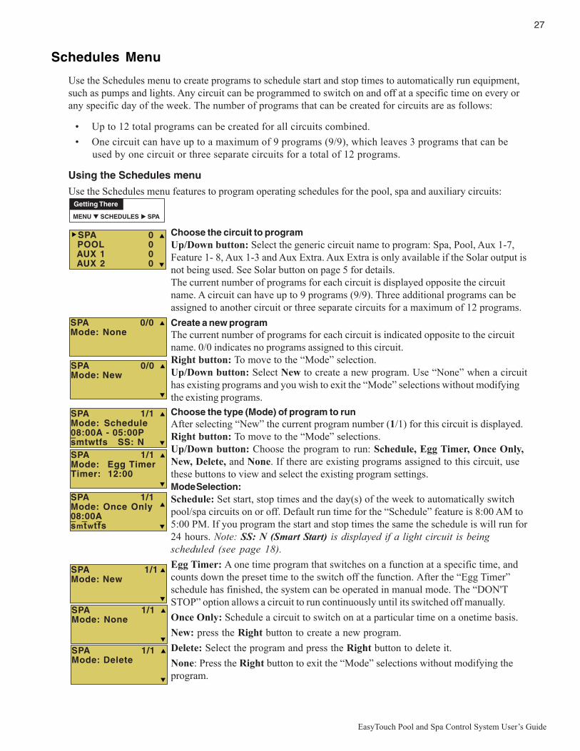
27
EasyTouch Pool and Spa Control System User’s Guide
Schedules Menu
Use the Schedules menu to create programs to schedule start and stop times to automatically run equipment,such as pumps and lights. Any circuit can be programmed to switch on and off at a specific time on every orany specific day of the week. The number of programs that can be created for circuits are as follows:
• Up to 12 total programs can be created for all circuits combined.
• One circuit can have up to a maximum of 9 programs (9/9), which leaves 3 programs that can beused by one circuit or three separate circuits for a total of 12 programs.
Using the Schedules menu
Use the Schedules menu features to program operating schedules for the pool, spa and auxiliary circuits:
Choose the circuit to programUp/Down button: Select the generic circuit name to program: Spa, Pool, Aux 1-7,Feature 1- 8, Aux 1-3 and Aux Extra. Aux Extra is only available if the Solar output isnot being used. See Solar button on page 5 for details.The current number of programs for each circuit is displayed opposite the circuitname. A circuit can have up to 9 programs (9/9). Three additional programs can beassigned to another circuit or three separate circuits for a maximum of 12 programs.
Create a new programThe current number of programs for each circuit is indicated opposite to the circuitname. 0/0 indicates no programs assigned to this circuit.Right button: To move to the “Mode” selection.Up/Down button: Select New to create a new program. Use “None” when a circuithas existing programs and you wish to exit the “Mode” selections without modifyingthe existing programs.
Choose the type (Mode) of program to runAfter selecting “New” the current program number (1/1) for this circuit is displayed.Right button: To move to the “Mode” selections.Up/Down button: Choose the program to run: Schedule, Egg Timer, Once Only,New, Delete, and None. If there are existing programs assigned to this circuit, usethese buttons to view and select the existing program settings.Mode Selection:Schedule: Set start, stop times and the day(s) of the week to automatically switchpool/spa circuits on or off. Default run time for the “Schedule” feature is 8:00 AM to5:00 PM. If you program the start and stop times the same the schedule is will run for24 hours. Note: SS: N (Smart Start) is displayed if a light circuit is beingscheduled (see page 18).
Egg Timer: A one time program that switches on a function at a specific time, andcounts down the preset time to the switch off the function. After the “Egg Timer”schedule has finished, the system can be operated in manual mode. The “DON'TSTOP” option allows a circuit to run continuously until its switched off manually.
Once Only: Schedule a circuit to switch on at a particular time on a onetime basis.
New: press the Right button to create a new program.
Delete: Select the program and press the Right button to delete it.
None: Press the Right button to exit the “Mode” selections without modifying theprogram.
SPA 0/0Mode: None
SPA 0 POOL 0 AUX 1 0 AUX 2 0
SPA 1/1Mode: Egg TimerTimer: 12:00
SPA 1/1Mode: Once Only08:00Asmtwtfs
_ _ _
SPA 1/1Mode: Delete
SPA 1/1Mode: None
SPA 0/0Mode: New
Getting There
MENU ▼ SCHEDULES SPA▲
SPA 1/1Mode: New
SPA 1/1Mode: Schedule08:00A - 05:00Psmtwtfs SS: N
_

28
EasyTouch Pool and Spa Control System User’s Guide
Schedules Menu (Continued)
Schedule your spa/pool pump to turn on
Use the Schedule feature to set the time and day(s) when to switch the filter pump on and rotate the pool orspa valves into the “Spa” or “Pool” position. The heater will automatically heat the spa or pool water up to theset point temperature as set in the “Heat” menu (see page 25). If the pool has a separate jet pump or blowercontrolled by AUX 1 and/or AUX 2 , these need to be scheduled separately.
Schedule ExampleWhen a circuit relay is switched on manually, it remains on until you either switch it off manually, or the nexttime the relay is scheduled to be switched off. For example, if the filter pump or any circuit is scheduled to runfrom 9:00 AM to 4:00 PM and the programmed schedule is turned OFF at 1:00 PM and then turned on at 1:10PM, the circuit will turn OFF at its programmed OFF time of 4:00 PM. But if the circuit is turned on after 4:00PM, the factory set Egg Timer of 12 hours is now engaged. So if the circuit was turned on at 6:00 PM thatcircuit will turn off at 6:00 AM (12 hours later). If the circuit was turned ON at 5:00 PM and because aprogrammed OFF time had been set to turn off at 4:00 PM, the circuit would operate for 11 hours. A spa orpool program can be overridden using the Spa button or Pool button to switch the circuit on. If you programthe start and stop times the same, the schedule will run for 24 hours if scheduled to run for one day. In“Service” mode, a pool or spa program can be overridden using the Filter (F) button and pool/spa Valves (V)button on the outdoor control panel in the EasyTouch load center. Note: The following example describeshow to use the “Schedule” feature to program the spa circuit to switch the filter pump on and rotate thevalves into the “Spa” position and switch the heater on. This example can also be used to programwhen to filter and heat your pool, and switch light or auxiliary circuits on or off.
To create a schedule for your spa or pool pump to turn on:
Press the Up/Down button to select the circuit to schedule then press the Rightbutton.Right button: Select Mode if there are existing programs. Skip this step to create anew program.Up/Down button: Select New to create a new program.Right button: To create a new program and enter the “Mode” settings.Up/Down button: 1/1 indicates that this circuit has one program. If there are existingprograms assigned to this circuit, use these buttons to view and select the existingprogram settings.Right button: To select the “Schedule” settings.Right button: Move to start and stop time settings.Up/Down and Right buttons: Set start and stop hour (A/P), minutes.The A (AM) and P (PM) time is set when setting the start and stop hour.Right button: Move to days of the week to run the program.Right and Up/Down buttons: By default the program is set to run all the days ofthe week. If you wish to edit which days to run the program, select the day of theweek, then press the Up/Down button to remove the bar from the top of the letter. Abar on top of the letter indicates the day selected to run the program.Press the Menu button to save the settings and to return to the Schedules menuoptions. Press the button again to return to the main menu options or press again toreturn to the main screen.
Getting There
MENU ▼ SCHEDULES SPA▲
SPA 0/0Mode: None (New)
SPA 0 POOL 0 AUX 1 0 AUX2 0
SPA 1/1Mode: Schedule08:00A - 05:00PSMTWTFS
_ _

29
EasyTouch Pool and Spa Control System User’s Guide
Using the Once Only feature
The “Once Only” feature allows you to program a circuit to switch on at a particular time and day on aonetime basis. A typical use for this feature is to have the spa and heater switch on before you get home fromwork for one evening. Unlike the regular “Schedule” timer, this feature does not repeat. After this event hasfinished, the program is automatically erased. The circuit must be switched off manually or wait for the 12hour automatic shut off. If you wish to override the 12 hour default shut-off time you can extend the time byusing the “Egg Timer” countdown feature (page 30).
Note: The following example describes how use the “Once Only” feature to program the spa circuit toswitch the filter pump on and rotate the valves into the “Spa” position and switch the heater on for onetime only. This example can also be used if you wanted to program when to filter and heat your pool,and switch light or auxiliary circuits on.
The set a “Once Only Timer” program for the spa:
Press the Up/Down button to select the circuit to schedule then press the Rightbutton.
Right button: Select Mode if there are existing programs. Skip this step to create anew program.Up/Down button: Select New to create a new program.Right button: To create a new program and enter the “Mode” settings.Up/Down button: 1/1 indicates that this circuit has one program. If there areexisting programs assigned to this circuit, use these buttons to view and select theexisting program settings.Right button: To select the ONCE ONLY settings.Right button: Move to start time settings.Up/Down and Right buttons: Set the start hour (A/P) and minutes. A (AM) and P(PM) time is set when setting the start hour. Note: if the Start Time is set to an hourwhich has already passed, then the program will be executed the following day.Another day of the week may also be chosen. The stop time will be 12 hours later, orcan be turned off manually. The 12-hour shut off can be changed to any length oftime by entering another program using the “Egg Timer” program (page 30).Right button: Move to day of the week to run the program.Right button: Select which day to run the program then press the Up/Down buttonto enable the bar on top of the letter. A bar on top of the letter indicates the dayselected to run the program.
Press the Menu button to save the settings and to return to the Schedules menuoptions. Press the button again to return to the main menu options or press again toreturn to the main screen.
Getting There
MENU ▼ SCHEDULES SPA▲
SPA 0/0Mode: None (New)
SPA 0 POOL 0 AUX1 0 AUX2 0
SPA 1/1Mode: Once Only08:00ASMTWTFS
_
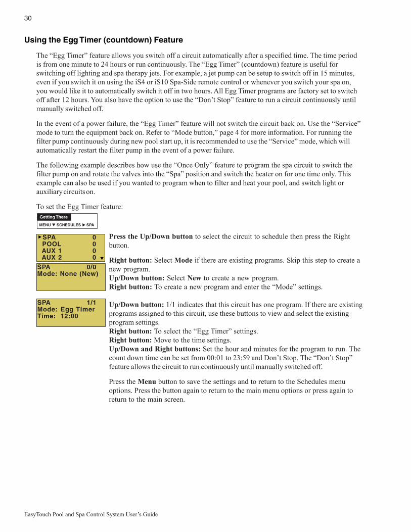
30
EasyTouch Pool and Spa Control System User’s Guide
Using the Egg Timer (countdown) Feature
The “Egg Timer” feature allows you switch off a circuit automatically after a specified time. The time periodis from one minute to 24 hours or run continuously. The “Egg Timer” (countdown) feature is useful forswitching off lighting and spa therapy jets. For example, a jet pump can be setup to switch off in 15 minutes,even if you switch it on using the iS4 or iS10 Spa-Side remote control or whenever you switch your spa on,you would like it to automatically switch it off in two hours. All Egg Timer programs are factory set to switchoff after 12 hours. You also have the option to use the “Don’t Stop” feature to run a circuit continuously untilmanually switched off.
In the event of a power failure, the “Egg Timer” feature will not switch the circuit back on. Use the “Service”mode to turn the equipment back on. Refer to “Mode button,” page 4 for more information. For running thefilter pump continuously during new pool start up, it is recommended to use the “Service” mode, which willautomatically restart the filter pump in the event of a power failure.
The following example describes how use the “Once Only” feature to program the spa circuit to switch thefilter pump on and rotate the valves into the “Spa” position and switch the heater on for one time only. Thisexample can also be used if you wanted to program when to filter and heat your pool, and switch light orauxiliary circuits on.
To set the Egg Timer feature:
Press the Up/Down button to select the circuit to schedule then press the Rightbutton.
Right button: Select Mode if there are existing programs. Skip this step to create anew program.Up/Down button: Select New to create a new program.Right button: To create a new program and enter the “Mode” settings.
Up/Down button: 1/1 indicates that this circuit has one program. If there are existingprograms assigned to this circuit, use these buttons to view and select the existingprogram settings.Right button: To select the “Egg Timer” settings.Right button: Move to the time settings.Up/Down and Right buttons: Set the hour and minutes for the program to run. Thecount down time can be set from 00:01 to 23:59 and Don’t Stop. The “Don’t Stop”feature allows the circuit to run continuously until manually switched off.
Press the Menu button to save the settings and to return to the Schedules menuoptions. Press the button again to return to the main menu options or press again toreturn to the main screen.
Getting There
MENU ▼ SCHEDULES SPA▲
SPA 1/1Mode: Egg TimerTime: 12:00
SPA 0/0Mode: None (New)
SPA 0 POOL 0 AUX 1 0 AUX 2 0

31
EasyTouch Pool and Spa Control System User’s Guide
Settings Menu: Clock
Use the Clock menu to set the EasyTouch system date and time. The day, time and AM/PM is displayed onthe main screen. The system clock settings are used for the EasyTouch system scheduled operations. TheEasyTouch system clock will continue to run if power is removed from the EasyTouch system at the loadcenter.
Clock
To set the system date and time:
Right button: Move to the day setting.Up/Down buttons: Set the day of the month.Right button: Move to the year setting.Up/Down buttons: Set the year.Right button: Move to the next set of settings (2/2).Up/Down buttons: Set Daylight Savings to Auto or Manual. Auto keep track of thesemi annual time changes. If you do not live in an area that observes daylight savingstime, choose Manual.Right button: Move to the clock adjustment setting. If the internal system clockloses time during the month, use this setting to set the number of seconds in fivesecond increments per month to automatically adjust the clock to the correct time.Up/Down buttons: Adjust the offset in five second increments.
Press the Menu button to save the settings and to return to the Settings menuoptions. Press the button again to return to the main menu options or press again toreturn to the main screen.
Getting There
MENU ▼ SETTINGS CLOCK▲
Date & Time 1/2
JAN 12 200909:20 AM
Date & Time 2/2
DayLt Sav: AutoClk Adj: 00:00
Settings Menu: IntelliFlo® (and IntelliPro® pump)
The EasyTouch system communicates with the IntelliFlo pump via a two-wire RS-485 cable (PN 350122).IntelliFlo operations can be controlled from the EasyTouch indoor and outdoor control panel and the EasyTouchwireless remote. EasyTouch supports the following pumps: IntelliFlo VF3050 (15-130 GPM), IntelliProVF3050 (15-130 GPM), IntelliFlo VS+SVRS (1100-3450 RPM), IntelliFlo VS3050 (400-3110 RPM),IntelliPro VS3050 (400-3450 RPM) and IntelliFlo VSF+SVRS. For more information refer to the followingmanuals: IntelliFlo VF 3050 (P/N 350075), IntelliFlo VS 3050 (P/N 357269), IntelliFlo VSF+SVRS (P/N351420).
How many IntelliFlo pumps will EasyTouch support?EasyTouch can support a total of two IntelliFlo (or IntelliPro) VF3050 or IntelliFlo VS3050 (or VSF+SVRS) pumpsin any combination with up to eight GPMs or RPMs per pump. For example pumps can be connected to
EasyTouch as follows:
• 1 IntelliFlo VF + 1 IntelliFlo VS (or VSF+SVRS)• 2 IntelliFlo VF• 2 IntelliFlo VS (or VSF+SVRS)
Note: IntelliFlo pumps cannot be connected in series with other pumps. Check valves must be used when apump is used in parallel with other pumps.

32
EasyTouch Pool and Spa Control System User’s Guide
Pump #1 Pump #2
Selecting the IntelliFlo PUMP TYPE
To access the IntelliFlo menu:
Up/Down button: Choose Pump #1. To assign a circuit to Pump #2, be sure tochange the pump to “ADDRESS 2”on the pump’s control panel.Right button: Select Pump #1.Right button: Select Pump Type. Note: To change the current pump type for Pump#1. press the Up/Down button and select Y, then press the Right button. Tocontinue to the Pump #1 settings menu, press the Right button (or Menu to exit).
Settings Menu: IntelliFlo® (Continued)
Connecting power to IntelliFloThe IntelliFlo pump is designed to be permanently connected to its power source. Typically the pump receivespower directly from the circuit breaker. No contactor or motor starter is required. The drive controls the startingand stopping of the pump. If the IntelliFlo pump is connected to an automation system, such as the EasyTouchautomation system, the drive must be powered up to receive and respond to the RS-485 serial communication fromthe automation system. However, the pump can be operated in “stand-alone” mode, starting and stopping whenpower is applied or removed. When the drive powers up it will return to the mode and run status that it was inwhen power was removed. This setup is appropriate if you need to use existing relays or timers.
MENU ▼ SETTINGS ▼ INTELLIFLO PUMP # 1
Getting There
▲
IntelliFlo VS 3050 Speed buttons (1-4)
Assigning an IntelliFlo VS 3050 pump address
Before assigning a pump address in the IntelliTouch indoor controlpanel, first set the address on the pump itself. If there is only onepump, it is always seen as pump #1 by IntelliTouch. In this case youdo not need to set the pump address. When using multiple IntelliFloVS 3050 pumps with IntelliTouch you need to assign an address toeach pump. The address can be set to #1, #2, #3, or #4. Theaddress set at the pump must match the IntelliFlo pump numberselected in the IntelliTouch indoor control panel.
To assign an IntelliFlo VS 3050 pump address:
1. Be sure that the pump is powered on and the green power LED is on.2. Press the Stop buttons to stop the pump.3. Press and hold both the Start and Stop buttons until the red LED will starts flashing, then press one of the
four speed buttons (1-4) to select which address to assign the pump. For example, if you are assigning thepump as pump #1, then press Speed button number 1.
4. Press and hold both the Start and Stop buttons to save the address. Repeat the process for the otherpumps.
Changing Pump1’sType will configit to default.Continue ? N
NOTE: INTELLIFLO IN “SERVICE MODE” - IntelliFlo pumps will STOP when IntelliTouch is in ‘Service” mode.
NOTE: INTELLIFLO “FREEZE” PROTECTION - If the IntelliFlo pump is on due to a freeze condition (not switchon from a relay circuit), and if a freeze speed is set in IntelliTouch, this setting takes priority even if the previoussetting is lower than the default circuit speed. If no “freeze” protection is set, the pump will be forced on at thedefault circuit speed. Any programmed or manual operation that actually switches on a circuit, will cause thepump to run at that speed if it is higher.

33
EasyTouch Pool and Spa Control System User’s Guide
SELECT PUMP TYPE: Up/Down buttons: Choose VS, VF or VSF+SVRS.Menu button: Press the MENU button to save selection and return to the selectedpump’s menu settings (see VS, VF and VSF pump settings descriptions below).
INTELLIFLO VS SPEEDS SETTING:Down button: Choose Speeds.Right button: Access the IntelliFlo VS speed (RPM) settings for Pump #1.Up/Down button: Select the circuit number 1 of 8 (1/8).Right button: Move to RPM to change the pump speed.Up/Down buttons: Set speed of the pump from 400 to 3450 RPM in increments of10 RPM. The default speed for each circuit correspond to the four speed buttons onthe IntelliFlo VS control panel is: Speed 1 button 750 RPM, Speed 2 button1500 RPM, Speed 3 button 2350 RPM, and Speed 4 button 3110 RPM.
Pump #1 Type
Type: VS
Pump #1 1/8RPM: 1200Circuit:[ POOL ]
Pump Type Speeds Priming Status
INTELLIFLO VSF+SVRS FLOW RATE SETTING:Down button: Choose Flow/Speeds.Right button: Access the IntelliFlo VSF+SVRS speed (RPM/GPM) settings forPump #2.Up/Down button: Select the circuit number 1 of 8 (1/8).Right button: Move to GPM to change the pump flow rate.Up/Down button: Select RPM or GPM. Press Up/Down button to togglebetween RPM and GPM and pressure setting (PSI).Right button (GPM): Move to GPM pump flow rate.Up/Down button: Set speed of the pump from 15 to 130 GPM. The default flow rateis 30 GPM. The preset speed for each button is: Speed 1 button 1100 RPM (30GPM), Speed 2 button 1500 RPM, Speed 3 button 2350 RPM, and Speed 4button 3110 RPM.Right button (GPM/PSI): Move to PSI (pounds per square inch) pressure setting.Up/Down button: Select the pump pressure setting from 1 to 30 PSI. See above forequivalent default RPM/GPM (speed/flow rate).
Pump #2 1/8GPM:30 PSI: 15Circuit:[ NONE ]
Pump Type Flow/Speeds Status
Pump #2 Type
Type: VSF+SVRS
VS and VSF+SVRS CIRCUIT SETTING:Right button: Move to the circuit names.Up/Down buttons: Assign the pump circuit: NONE, SPA, POOL, AUX 1-7,FEATURE 1-8 (EasyTouch 8), AUX 1-3 (EasyTouch 4), FEATURE 1-8, AUXEXTRA (only if Solar is not selected, see page 46), HEATER, POOLHEATER, SPA HEATER, FREEZE, POOL/SPA, and SOLAR/HEAT. AUXEXTRA is only available if the Solar output (J17) plug on the EasyTouch motherboardis not being used for solar equipment.Right button: Press the Up arrow button and go to the next circuit page settings(2/8) and repeat the previous steps.
When finished setting up the circuits, press the Menu button to save the settings andto return to the Settings menu options. Press the button two times to return to themain screen.
iS4/iS10/SpaCommand spa-side remote pumpspeed control: TheIntelliFlo pump speedcan be incrementallyincreased ordecreased from thespa-side remote. See“10 B Pump Control”in the “Settings” menu(page 50).
Pump #2 1/8GPM:30 PSI: 15Circuit:[ AUX 1 ]
IntelliFlo VS and VSF+SVRS Settings
INTELLIFLO VS STATUS SETTING:Down button: Choose STATUS.Right button: View the current VS status.Menu: Press MENU to exit.
GPM: 301200 RPM 12 WWatts: 10Status: GOOD
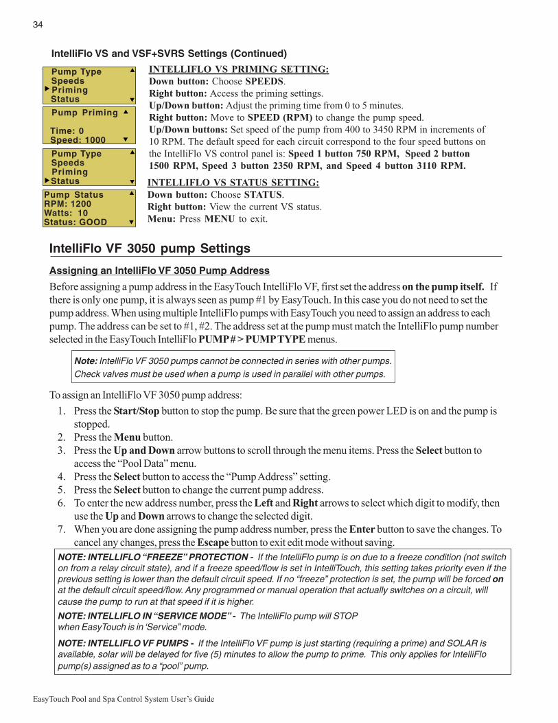
34
EasyTouch Pool and Spa Control System User’s Guide
INTELLIFLO VS STATUS SETTING:Down button: Choose STATUS.Right button: View the current VS status.Menu: Press MENU to exit.
IntelliFlo VF 3050 pump Settings
Assigning an IntelliFlo VF 3050 Pump Address
Before assigning a pump address in the EasyTouch IntelliFlo VF, first set the address on the pump itself. Ifthere is only one pump, it is always seen as pump #1 by EasyTouch. In this case you do not need to set thepump address. When using multiple IntelliFlo pumps with EasyTouch you need to assign an address to eachpump. The address can be set to #1, #2. The address set at the pump must match the IntelliFlo pump numberselected in the EasyTouch IntelliFlo PUMP # > PUMP TYPE menus.
Note: IntelliFlo VF 3050 pumps cannot be connected in series with other pumps.Check valves must be used when a pump is used in parallel with other pumps.
To assign an IntelliFlo VF 3050 pump address:
1. Press the Start/Stop button to stop the pump. Be sure that the green power LED is on and the pump isstopped.
2. Press the Menu button.3. Press the Up and Down arrow buttons to scroll through the menu items. Press the Select button to
access the “Pool Data” menu.4. Press the Select button to access the “Pump Address” setting.5. Press the Select button to change the current pump address.6. To enter the new address number, press the Left and Right arrows to select which digit to modify, then
use the Up and Down arrows to change the selected digit.7. When you are done assigning the pump address number, press the Enter button to save the changes. To
cancel any changes, press the Escape button to exit edit mode without saving.
NOTE: INTELLIFLO “FREEZE” PROTECTION - If the IntelliFlo pump is on due to a freeze condition (not switchon from a relay circuit state), and if a freeze speed/flow is set in IntelliTouch, this setting takes priority even if theprevious setting is lower than the default circuit speed. If no “freeze” protection is set, the pump will be forced onat the default circuit speed/flow. Any programmed or manual operation that actually switches on a circuit, willcause the pump to run at that speed if it is higher.
NOTE: INTELLIFLO IN “SERVICE MODE” - The IntelliFlo pump will STOPwhen EasyTouch is in ‘Service” mode.
NOTE: INTELLIFLO VF PUMPS - If the IntelliFlo VF pump is just starting (requiring a prime) and SOLAR isavailable, solar will be delayed for five (5) minutes to allow the pump to prime. This only applies for IntelliFlopump(s) assigned as to a “pool” pump.
INTELLIFLO VS PRIMING SETTING:Down button: Choose SPEEDS.Right button: Access the priming settings.Up/Down button: Adjust the priming time from 0 to 5 minutes.Right button: Move to SPEED (RPM) to change the pump speed.Up/Down buttons: Set speed of the pump from 400 to 3450 RPM in increments of10 RPM. The default speed for each circuit correspond to the four speed buttons onthe IntelliFlo VS control panel is: Speed 1 button 750 RPM, Speed 2 button1500 RPM, Speed 3 button 2350 RPM, and Speed 4 button 3110 RPM.
IntelliFlo VS and VSF+SVRS Settings (Continued)
Pump Priming
Time: 0 Speed: 1000
Pump StatusRPM: 1200Watts: 10Status: GOOD
Pump Type Speeds Priming Status
Pump Type Speeds Priming Status

35
EasyTouch Pool and Spa Control System User’s Guide
Filtering -Pool Size/Gallons: 0 - 255 (Kgals) - Turnovers per day: (1 - 8)Filtering Manual Filter GPM: (15 - 130) Default 30 GPM: Manual Filter sets the flow at whichthe pump will run if it is turned on manually. The IntelliFlo pump will only run in the 'Filter'mode during the programmed times. For example, if the pump is programmed (start/stoptimes) for the pool circuit to run from 8:00 AM to 4:00 PM everyday. This program or programsare used by IntelliFlo to calculate at what speed it must run given those ‘ON’ times to achievethe turnover(s) for that sized pool for the basic filter mode.Priming - Max Prime Flow GPM: (30 - 130) Default 55 GPM: Every time the pump starts thisparameter will negotiate the maximum flow of the pump. If the flow is too high, equipmentdamage can occur. If the flow is to low the pump will not prime. This “flow” is systemdependent and may require adjustment. The pump will never flow more than this parameter isset to, however, it is common for the pump to ramp up and down quickly while priming.Always try to keep this flow as low as possible for cost savings and safety.Continue on next page.
IntelliFlo VF 3050 Pump Settings
To access the IntelliFlo VF menu settings:
Up/Down button: Choose Pump #1 (or Pump #2) to access the IntelliFlo VF pumpsettings. If the VF pump is assigned to Pump #2 circuit, be sure to change the pumpto “ADDRESS 2”on the pump’s control panel.Right button: Select Pump #1 or Pump #2.TO CHANGE THE PUMP TYPE: Press the Right button to Select PumpType. Press the Up/Down button and select Y, then press the Right button. Pressthe Up/Down button to change the pump type to VS, VF or VSF+SVRS. PressMENU to save and return to the selected pump’s settings. See page 32 for details.FILT. CIRCUIT: Press Down button, Choose FILT > CIRCUIT. Press Up/Down button to select the pool filter circuit: NONE, SPA, POOL, AUX 1-7 (ET8),AUX 1-3 (ET4) and FEATURE 1-8. Press MENU to save.VF FLOWS: Press Down button: Choose Flows. Press Right button: Accessthe IntelliFlo VF flow settings. Press the Up/Down buttons to set GPM (15-130).Press Right button to CIRCUIT for circuit 1 of 8. Assign the circuit: NONE, SPA,POOL, AUX 1-7 (ET8), AUX 1-3 (ET4), FEATURE 1-8, SOLAR (if enabled inthe Solar menu) or AUX EXTRA (only if Solar is not selected, see page 25 and 42),HEATER, POOL HEATER, SPA HEATER, FREEZE, and HI_SPEED. AUXEXTRA is only available if the Solar output (J17) plug on the EasyTouch motherboardis not being used for solar equipment. After circuit selection is finished, press Rightbutton: Press the Up arrow button and go to the next circuit page settings (2/8) andrepeat GPM and CIRCUIT settings setup. Up to eight (8) circuits can be assigned.When finished , Press the MENU button to save and exit to previous menu.
Press Down/Up button to select FILTERING, PRIMING, BACKWASH,VACUUM, or STATUS. Press the Right button to access settings: Press theUp/Down buttons to set parameters. See IntelliFlo VF parameter descriptionsbelow:When finished setting up a parameter, press the Menu button to save the settings andto return to the IntelliFlo VF setting menu. When finished setting up all of the IntelliFloVF pump parameters, press the Menu button until the main screen displays.
MENU ▼ SETTINGS ▼ INTELLIFLO PUMP # 1
Getting There
▲
Pump FilteringSize : 1500Turns : 2Man Filt: 0
Pump PrimingMax Flow : 55Max Time : 5Sys time : 0
iS4/iS10/SpaCommand spa-side remote pumpspeed control: TheIntelliFlo pump speedcan be incrementallyincreased ordecreased from thespa-side remote. See“10 B Pump Control”in the “Settings” menu(page 50).
Pump #1 Pump #2
Priming Backwash Vacuum Status
Pump Type Filt. Circuit Flows Filtering
Pump #1 1/8GPM : 30Circuit:[ AUX 1 ]
Pump #1 1/8GPM : 30Circuit:[ AUX 1 ]
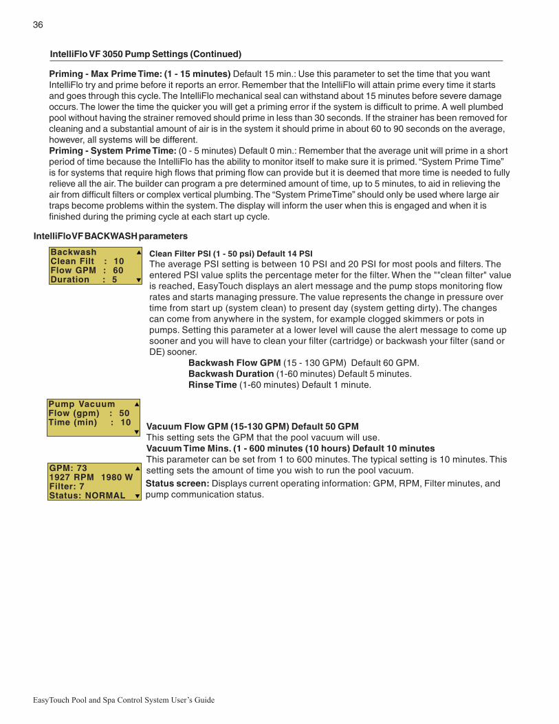
36
EasyTouch Pool and Spa Control System User’s Guide
Priming - Max Prime Time: (1 - 15 minutes) Default 15 min.: Use this parameter to set the time that you wantIntelliFlo try and prime before it reports an error. Remember that the IntelliFlo will attain prime every time it startsand goes through this cycle. The IntelliFlo mechanical seal can withstand about 15 minutes before severe damageoccurs. The lower the time the quicker you will get a priming error if the system is difficult to prime. A well plumbedpool without having the strainer removed should prime in less than 30 seconds. If the strainer has been removed forcleaning and a substantial amount of air is in the system it should prime in about 60 to 90 seconds on the average,however, all systems will be different.Priming - System Prime Time: (0 - 5 minutes) Default 0 min.: Remember that the average unit will prime in a shortperiod of time because the IntelliFlo has the ability to monitor itself to make sure it is primed. “System Prime Time”is for systems that require high flows that priming flow can provide but it is deemed that more time is needed to fullyrelieve all the air. The builder can program a pre determined amount of time, up to 5 minutes, to aid in relieving theair from difficult filters or complex vertical plumbing. The “System PrimeTime” should only be used where large airtraps become problems within the system. The display will inform the user when this is engaged and when it isfinished during the priming cycle at each start up cycle.
IntelliFlo VF 3050 Pump Settings (Continued)
IntelliFlo VF BACKWASH parameters
BackwashClean Filt : 10Flow GPM : 60Duration : 5
Clean Filter PSI (1 - 50 psi) Default 14 PSIThe average PSI setting is between 10 PSI and 20 PSI for most pools and filters. Theentered PSI value splits the percentage meter for the filter. When the ""clean filter" valueis reached, EasyTouch displays an alert message and the pump stops monitoring flowrates and starts managing pressure. The value represents the change in pressure overtime from start up (system clean) to present day (system getting dirty). The changescan come from anywhere in the system, for example clogged skimmers or pots inpumps. Setting this parameter at a lower level will cause the alert message to come upsooner and you will have to clean your filter (cartridge) or backwash your filter (sand orDE) sooner.
Backwash Flow GPM (15 - 130 GPM) Default 60 GPM.Backwash Duration (1-60 minutes) Default 5 minutes.Rinse Time (1-60 minutes) Default 1 minute.
Pump VacuumFlow (gpm) : 50Time (min) : 10
GPM: 731927 RPM 1980 WFilter: 7Status: NORMAL
Vacuum Flow GPM (15-130 GPM) Default 50 GPMThis setting sets the GPM that the pool vacuum will use.Vacuum Time Mins. (1 - 600 minutes (10 hours) Default 10 minutesThis parameter can be set from 1 to 600 minutes. The typical setting is 10 minutes. Thissetting sets the amount of time you wish to run the pool vacuum.Status screen: Displays current operating information: GPM, RPM, Filter minutes, andpump communication status.

37
EasyTouch Pool and Spa Control System User’s Guide
Settings Menu: IntelliChlor
While the EasyTouch system is in normal operating mode (“Pool,” “Spa” mode or “Spa Fill (Spillway),” it willcontrol the IntelliChlor chlorine output level. The amount of chlorine introduced into the pool is determined bythe amount of salt in the water, water temperature, and the amount of time the pool pump is running in “Pool”mode. Note: While in “Freeze Protection” mode, IntelliChlor will not operate or produce chlorine during thetime that the filter pump is operating. For more information, refer to the IntelliChlor Electronic ChlorineGenerator User’s Guide (P/N 520589).
IntelliChlor
To setup the IntelliChlor:
Right button: Enable/Disable IntelliChlor. (To select SuperChlor, run hours, press theUp/Down button - 2/2).Up/Down buttons: Select Yes or No to enable or disable IntelliChlor.Right button: POOL Mode “50%” setting.Up/Down buttons: Set the chlorination output level for the pool water from 0 to100%. EasyTouch will determine the chlorinator output level when the system isoperating in “Spa” or “Pool” mode. The amount of chlorine introduced into the pool/sap is determined by the amount of salt in the water, water temperature, and theamount of time the pool/spa operates in these modes mode.Right button: SPA Mode “0%” setting.Up/Down buttons: Set the chlorination output level for the spa water from 0 to 20%.To prevent over chlorination of the spa, the EasyTouch system will automatically dropthe chlorine output levels to 1/20th of the current pool output when the spa is switchedon. For example, if the pool output level is set to 60%, when the spa is switched on,the chlorination level is reduced to 3%.Right button: Move to the next set of settings (2/2).Up/Down buttons: Select 2/2.Right button: Move the Super Chlorination settings.Up/Down buttons: Set Super Chlorination On or Off. See note below about SuperChlorination.Right button: Move to “Run Hours” setting.Up/Down buttons: Set the number of hours to run Super Chlorination. 24 hours isthe default setting. Run hours can be set from 0 to 72 hours.Press the Menu button to save the settings and to return to the Settings menuoptions. Press the button again to return to the main menu options or press again toreturn to the main screen.
Note: For IntelliChlor status messages, see “Diagnostics: Chlorinator” page 57.
About Super Chlorination: The Super Chlorination feature is used to introduce large amounts of chlorine intothe pool water if there has been heavy rain fall, many bathers in the pool, cloudy water conditions, etc. WhenSuper Chlorination is enabled, the system will switch on the filter pump, set the pool/spa valves to the correctposition, and set the IntelliChlor chlorine generator to maximum output. This process continues for 24 hours. Atthe end of the Super Chlorination process, the pool will return to normal operation. It is possible to manuallystop the Super Chlorination process and switch off the filter pump using the Filter (F) button on the main controlpanel at the pool equipment pad. When the filter pump is switched on again using the Filter (F) button, the SuperChlorine process will resume for the duration of time left.
IntelliChlor 1/2
Enable: NoLevel: 50%
IntelliChlor 2/2
Super Chlr: OffRun Hours: 24
MENU ▼ SETTINGS ▼ INTELLICHLOR
Getting There

38
EasyTouch Pool and Spa Control System User’s Guide
IntelliChem
To access the IntelliChem pH and ORP settings:
PH/ORP Values: Press the Right button to access the pH and OPR set point valuesscreen. Use the Up/Down button to adjust the pH set point value. Press the Rightbutton again to set the ORP set point value. Press MENU to save and return to theprevious screen.
pH Set Point: Displays the current pH set point value. The adjustable range is from 7 to8 in increments of 0.1. The default pH set point value is 7.5.
ORP Set Point: Displays the current ORP set point value. Use the Up/Down button toadjust the ORP set point value. The adjustable range is from 650 to 800 in increments of10. The default ORP set point value is 700 (chlorine level of 3.0 ppm). The ORP set pointis the value that IntelliChem will try to achieve based on the actual chlorine level (ppm).
STATUS: Displays the current communication link between EasyTouch and IntelliChemvia the RS-485 cable. IChem Comm Error: Check the RS-485 communication cable isconnected to the COM port on the EasyTouch circuit board.
Level Gauge indicator: Press the Up/Down button to “fill” the gauge icon so that itvisually represents the same amount of acid available in the container. Press Up/Downbutton six (6) times to fill the gauge (three times to half fill the gauge). Six horizontal barsrepresent chlorine (or bromine) supply is full. One bar indicates the supply is nearly empty.
pH VAL 7.0pH Set: 7.5ORP VAL: 650ORP SET: 750
IntelliChemPH/ORP ValuesStatusSat Index
IntelliChemPH/ORP ValuesStatusSat Index
IntelliChemPH/ORP ValuesStatusSat Index
CH: 245 TDS: 0TA: 75 CYA: 18SI: NA TMP: 0 IDEAL
ClockIntelliFloIntelliChlorIntelliChem
IntelliChem provides the EasyTouch system with continual analysis of your swimming pool water sanitationand pH levels, providing real-time status information to dispense the proper amount of muriatic acid (pHreducer) and chlorine or bromine for the correct sanitization and pH balance. IntelliChem operates with orwithout a salt chlorine generator to provide a self-replenishing supply of chlorine generated from salt. Formore information, refer to the IntelliChem Installation and User’s Guide (P/N 521363).From the IntelliChem menu you can adjust the pH and Oxidation Reduction Potential (ORP) set point values tomeet pool and spa chemistry standards for your pool. A status screen displays a user adjustable pH and OPRfuel gauge which visually represents the same amount of chemicals available in pH and ORP container.
Settings Menu: IntelliChem
MENU ▼ SETTINGS ▼ INTELLICHEM
Getting There
Sat Index: To access the Sat Index settings, press the Up/Down button then press theRight button. Use the Up/Down button to adjust the levels/values for: CH (calciumhardness), TDS (Total Dissolved Solids), TA (total alkalinity), CYA (cyanuricacid) and TMP (current temperature). Note: See table below for ideal SaturationIndex levels.SI: The saturation Index is displayed. IDEAL: Optimum levels. CORROSIVE: pH toolow. SCALING:Press the Menu button three times to return to the main screen.
Note: Use the Langelier Saturation Index (LSI) Calculator to diagnose the water balance in your pool. Water witha LSI of 1.0 is one pH unit above saturation. Reducing the pH by one unit will bring the water into equilibrium. To usethe LSI calculator, refer to: http://www.pentairpool.com/pool-owner/resources/calculators/langelier/
Recommended Pool Chemistryph range: 7.2 to 7.6ORP range: 650 to 750Alkanlinity: 80 to 120 ppmCalcium Hardness: 200 - 500 ppmCyanuric Acid/Stabilizer: 30 ppm
pH Lv1:ORP Lv1:ICHEM: ONORP Dosage Limit

39
EasyTouch Pool and Spa Control System User’s Guide
SAT INDEX: The Saturation Index (SI), also called the Langelier Index, is a chemical equation or formula used todiagnose the water balance in the pool. The Saturation Index formula is SI = pH + TF + CF + AF - 12.1. To calculatethe Saturation Index, you must first test the pool water for pH, temperature, calcium hardness, and total alkalinity.Refer to a chart for assigned values for your hardness, and alkalinity readings then add these to your pH value.Subtract 12.1, which is the constant value assigned to Total Dissolved Solids and a resultant number will be produced.A result between -0.3 and +0.5 indicates balanced water. Test results not within these values require chemicaladjustments to achieve balance. This formula is more or less reliable but not guaranteed. In some cases, individualreadings for pH, calcium, and alkalinity might be beyond normal recommendations, however, combined within theformula can produce “balanced water.” The SI is useful to pinpoint potential water balance problems.
pH: pH produced by IntelliChlor SCG is close to Neutral pH. However, other factors usually cause the pH of thepool water to rise. Therefore, the pH in a pool chlorinated by IntelliChlor tends to stabilize at approximately 7.8.This is within APSP standards. If the pool pH rises above 7.8, have a pool professional test to see if other factorssuch as high Calcium Hardness or Total Alkalinity are the cause and then balance accordingly.
pH Level Test: Test the pH level of your pool water with a reliable test method. If necessary, adjust accordingto your pool professional’s recommendations. APSP’s recommended ideal range for pH is 7.4 to 7.6. Note: Neveruse dry acid (sodium bisulfate) to adjust pH in arid geographic areas with excessive evaporation and minimaldilution of pool water with fresh water. A buildup of byproducts can damage the IntelliChlor SCG
Calcium Hardness: Recommended range for calcium hardness is 200-400 ppm. Calcium Hardness levels should betested weekly. Calcium hardness is the calcium carbonate scale deposited on pool surfaces. The test for CalciumHardness is a measure of how “hard” or “soft” the water is testing. “Hard” water can have high levels of calciumand magnesium. If these levels are too high the water becomes saturated and will leave calcium carbonate scaledeposits (a “white-ish,” crystallized rough spot) on any surface inside the pool. If the levels are too low, the waterbecomes “soft” and will corrode surfaces inside the pool. Use TSP or Hydroquest 100 to lower Calcium Hardnesslevels that are too high or add water to the pool which has a lower calcium hardness content. Levels which are toolow require the addition of calcium chloride.
Total Dissolved Solids (TDS): Adding salt to pool water will raise the TDS level. While this does not adverselyaffect the pool water chemistry or clarity, the pool water professional testing for TDS must be made aware salthas been added to the IntelliChlor system. The individual performing the TDS test may then subtract the salinitylevel to arrive at a TDS level that would be compatible to a TDS reading for a non-salt water pool.
Total Alkalinity: APSP’s recommended ideal range for total alkalinity is 80 to 120 ppm for “gunite” and con-crete pools and 125-170 ppm for painted, vinyl, and fiberglass pools. Test levels weekly and adjust according toyour pool professional’s recommendations. Alkalinity can be described as a buffer that keeps pH in order. pHdepends on the ability of the alkalinity in the water to withstand the changes in pH. If the alkalinity is too high,adding acid (similar to pH) lowers the level. Adding a base (e.g sodium bicarbonate) when alkalinity is low, raisesthe level. The level of alkalinity in the water is a measurement of all carbonates, bicarbonates, hydroxides, andother alkaline substances found in the pool water.
Cyanuric Acid: Cyanuric acid is needed in outdoor pools to help to stabilize and maintain proper levels ofchlorine. 90% of unstabilized chlorine is destroyed by the UV radiation from the sun within two hours. Cyanuricacid stabilizes chlorine in water from UV degradation. When using the IntelliChlor SCG, the cyanuric acid levelshould be maintained between 30-50 ppm (50ppm maximum).

40
EasyTouch Pool and Spa Control System User’s Guide
Settings Menu: Heat Pump COM (UltraTemp® Heat Pump)
Heat Pump Com screen
From the Heat Pump Com screen you can view the current UltraTemp® operation status, and set the unit tooperate with for heating only, cooling only, or both heating and cooling if the unit is reversible. Connection fromUltraTemp is via the COM PORT on the EasyTouch motherboard. See page 67 for UltraTemp to EasyTouchCOM port wiring information. The UltraTemp must be set to default ADDRESS 1. One UltraTemp unit can beconnected to EasyTouch.
Note: Once the UltraTemp is enabled, use the Left and Right arrow buttons to adjust the UltraTemptemperature and cooling, (see page 3).
Heat Pump Com
To access Heat Pump Com (UltraTemp) settings menu:
Right button: Access the “Settings” menu.Up/Down buttons: Select Yes or No to enable or disable UltraTemp.Right button: Move to the “Heating” setting.Up/Down buttons: Select Yes or No to use for heating.Right button: Move to the “Cooling” setting.Up/Down buttons: Select Yes or No to use for cooling only or if the unit isreversible select both heating and cooling.
Press the Menu button to save the settings and to return to the Heat Pump ComSettings and Status menu options.Press the Menu button three times to return to the main screen.
To access Heat Pump Com (UltraTemp) Status menu:
MENU ▼ SETTINGS ▼ HEAT PUMP COM STATUS
Getting There
▲
Right button: To view the current UltraTemp status.
Press the Menu button to return to the main screen.
MENU ▼ SETTINGS ▼ HEAT PUMP COM SETTINGS
Getting There
▲
Status
[ OP NORMAL ] <MENU> = EXIT
Settings Status
Heat Pump ComEnable : YesHeating : YesCooling : Yes
Settings Status
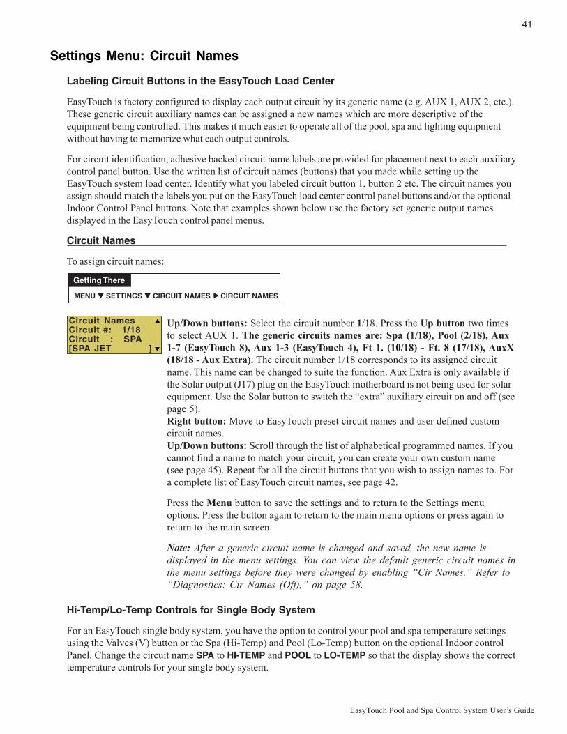
41
EasyTouch Pool and Spa Control System User’s Guide
Settings Menu: Circuit Names
Labeling Circuit Buttons in the EasyTouch Load Center
EasyTouch is factory configured to display each output circuit by its generic name (e.g. AUX 1, AUX 2, etc.).These generic circuit auxiliary names can be assigned a new names which are more descriptive of theequipment being controlled. This makes it much easier to operate all of the pool, spa and lighting equipmentwithout having to memorize what each output controls.
For circuit identification, adhesive backed circuit name labels are provided for placement next to each auxiliarycontrol panel button. Use the written list of circuit names (buttons) that you made while setting up theEasyTouch system load center. Identify what you labeled circuit button 1, button 2 etc. The circuit names youassign should match the labels you put on the EasyTouch load center control panel buttons and/or the optionalIndoor Control Panel buttons. Note that examples shown below use the factory set generic output namesdisplayed in the EasyTouch control panel menus.
Circuit Names
To assign circuit names:
Up/Down buttons: Select the circuit number 1/18. Press the Up button two timesto select AUX 1. The generic circuits names are: Spa (1/18), Pool (2/18), Aux1-7 (EasyTouch 8), Aux 1-3 (EasyTouch 4), Ft 1. (10/18) - Ft. 8 (17/18), AuxX(18/18 - Aux Extra). The circuit number 1/18 corresponds to its assigned circuitname. This name can be changed to suite the function. Aux Extra is only available ifthe Solar output (J17) plug on the EasyTouch motherboard is not being used for solarequipment. Use the Solar button to switch the “extra” auxiliary circuit on and off (seepage 5).Right button: Move to EasyTouch preset circuit names and user defined customcircuit names.Up/Down buttons: Scroll through the list of alphabetical programmed names. If youcannot find a name to match your circuit, you can create your own custom name(see page 45). Repeat for all the circuit buttons that you wish to assign names to. Fora complete list of EasyTouch circuit names, see page 42.
Press the Menu button to save the settings and to return to the Settings menuoptions. Press the button again to return to the main menu options or press again toreturn to the main screen.
Note: After a generic circuit name is changed and saved, the new name isdisplayed in the menu settings. You can view the default generic circuit names inthe menu settings before they were changed by enabling “Cir Names.” Refer to“Diagnostics: Cir Names (Off),” on page 58.
MENU ▼ SETTINGS ▼ CIRCUIT NAMES CIRCUIT NAMES
Getting There
▲
Circuit NamesCircuit #: 1/18Circuit : SPA[SPA JET ]
Hi-Temp/Lo-Temp Controls for Single Body System
For an EasyTouch single body system, you have the option to control your pool and spa temperature settingsusing the Valves (V) button or the Spa (Hi-Temp) and Pool (Lo-Temp) button on the optional Indoor controlPanel. Change the circuit name SPA to HI-TEMP and POOL to LO-TEMP so that the display shows the correcttemperature controls for your single body system.

42
EasyTouch Pool and Spa Control System User’s Guide
EasyTouch Circuit NamesAERATORAIR BLOWERAUX 1AUX 2AUX 3AUX 4AUX 5AUX 6AUX 7AUX 8AUX 9AUX 10AUX EXTRABACKWASHBACK LIGHTBBQ LIGHTBEACH LIGHTBOOSTER PUMPBUG LIGHTCABANA LTSCHEM. FEEDERCHLORINATORCLEANERCOLOR WHEELDECK LIGHTDRAIN LINEDRIVE LIGHTEDGE PUMPENTRY LIGHTFANFIBER OPTICFIBER WORKSFILL LINEFLOOR CLNRFOGGERFOUNTAINFOUNTAIN 1FOUNTAIN 2FOUNTAIN 3FOUNTAINSFRONT LIGHTGARDEN LTSGAZEBO LTSHIGH SPEEDHI-TEMPHOUSE LIGHTJETSLIGHTSLOW SPEEDLO-TEMP
Custom Circuit Names (11 characters maximum)
USERNAME-01 ____________________
USERNAME-02 ____________________
USERNAME-03 ____________________
USERNAME-04 ____________________
USERNAME-05 ____________________
USERNAME-06 ____________________
USERNAME-07 ____________________
USERNAME-08 ____________________
USERNAME-09 ____________________
USERNAME-10 ____________________
MALIBU LTSMISTMUSICNOT USEDOZONATORPATH LIGHTSPATIO LTSPERIMETER LPG2000POND LIGHTPOOL PUMPPOOLPOOL HIGHPOOL LIGHTPOOL LOWPOOL SAMPOOL SAM 1POOL SAM 2POOL SAM 3SECURITY LTSLIDESOLARSPASPA HIGHSPA LIGHTSPA LOWSPA SALSPA SAMSPA WTRFLLSPILLWAYSPRINKLERSSTREAMSTATUE LTSWIM JETSWTR FEATUREWTR FEAT LTWATERFALLWATERFALL 1WATERFALL 2WATERFALL 3WHIRLPOOLWTRFL LGHTYARD LIGHTFEATURE 1FEATURE 2FEATURE 3FEATURE 4FEATURE 5FEATURE 6FEATURE 7FEATURE 8

43
EasyTouch Pool and Spa Control System User’s Guide
Settings Menu: Circuit Functions
Assigning Circuit Functions
From the “Circuit Functions” menu you can assign special logic to the cleaner pump, spa spillway, lights andMagicStream laminar circuits. For example, when setting up an automatic pool cleaner pump, you wouldassign the circuit function “MASTER CLEANER.” With this "Cleaner" logic the cleaner pump would forcethe filter pump on, and the cleaner pump would start after a delay of five minutes. The cleaner pump wouldautomatically shut off whenever the spa and/or solar is switched on.
Freeze Protection
Freeze protection switches on a circuit if the outside air temperature sensor detects the temperature is gettingclose to freezing (below 35° F (40° C)). The system will switch on all circuits that have been assigned freezeprotection, and runs the circuits for 15 minutes to stop the pipes from freezing. This is especially important ifthere is a pool and spa combination. If freeze protection is set to both the spa and pool circuits, the filter pumpswitches on and the pool and spa valves alternate every 15 minutes to keep the water moving in both the pooland spa. This process continues until the freeze condition is over.
Circuit Functions
To assign a circuit function and freeze protection:
Up/Down buttons: Choose the circuit name (displayed on the second line). Thegeneric circuits names are: SPA [MASTER SPA - Freeze protection on bydefault], POOL [MASTER POOL - Freeze protection on by default], AUX 1-7(EasyTouch 8), AUX 1-3 (EasyTouch 4), FEATURE 1-8 and AUX EXTRA orSOLAR (if enabled in the Solar menu). AUX EXTRA is only available if theSolar output (J17) plug on the EasyTouch motherboard is not being used for solarequipment. Use the Solar button to switch the “extra” auxiliary circuit on and off (seepage 5).Right button: Move to the “Circuit Function” setting to select the circuit function forthe select circuit name displayed on the line above.Up/Down buttons: Select the circuit function. This is the circuit that you wish toassign the function logic to. For a complete list of preset circuit functions, see“Preset Circuit Functions,” on page 44.Right button: Move to Freeze Protection setting.Up/Down buttons: Select Yes or No to assign freeze protection to this circuit. If“Yes” is selected, the circuit will switch on if the air temperature drops to 35° F.Note: for the POOL circuit the filter pump will have freeze protection. For theSPA circuit the filter pump will run and the pool/spa valves will switch betweenpool and spa at 15 minutes intervals throughout the freeze condition. For theMASTER CLEANER circuit freeze protection is generally not needed for poolcleaner pumps since they get water flow from the filter pump. Just make surethat POOL has freeze protection.
Press the Menu button to save the settings and to return to the Settings menuoptions. Press the button again to return to the main menu options or press again toreturn to the main screen.
MENU ▼ SETTINGS ▼ CIRCUIT Func. CIRCUIT/ Func.
Getting There
▲
Circuit/Func.:[SPA ][Master Spa ]Freeze: Yes
Circuit/Func.:[AUX 1 ][LIGHT ]Freeze: No
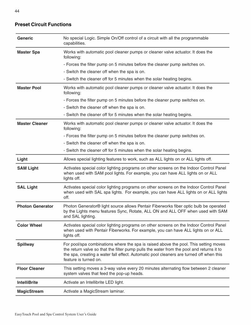
44
EasyTouch Pool and Spa Control System User’s Guide
Preset Circuit Functions
cireneG elbammargorpehtllahtiwtiucricafolortnocffO/nOelpmiS.cigoLlaicepsoN.seitilibapac
apSretsaM ehtseodtI.rotautcaevlavrenaelcrospmuprenaelcloopcitamotuahtiwskroW:gniwollof
.nosehctiwspmuprenaelcehterofebsetunim5nopmupretlifehtsecroF-
.nosiapsehtnehwfforenaelcehthctiwS-
.snigebgnitaehralosehtnehwsetunim5roffforenaelcehthctiwS-
looPretsaM ehtseodtI.rotautcaevlavrenaelcrospmuprenaelcloopcitamotuahtiwskroW:gniwollof
.nosehctiwspmuprenaelcehterofebsetunim5nopmupretlifehtsecroF-
.nosiapsehtnehwfforenaelcehthctiwS-
.snigebgnitaehralosehtnehwsetunim5roffforenaelcehthctiwS-
renaelCretsaM ehtseodtI.rotautcaevlavrenaelcrospmuprenaelcloopcitamotuahtiwskroW:gniwollof
.nosehctiwspmuprenaelcehterofebsetunim5nopmupretlifehtsecroF-
.nosiapsehtnehwfforenaelcehthctiwS-
.snigebgnitaehralosehtnehwsetunim5roffforenaelcehthctiwS-
thgiL .ffosthgilLLAronosthgilLLAsahcus,krowotserutaefgnithgillaicepsswollA
thgiLMAS lenaPlortnoCroodnIehtnosneercsrehtonosmargorpgnithgilroloclaicepssetavitcALLAronosthgilLLAevahnacuoy,elpmaxeroF.sthgilloopMAShtiwdesunehw
.ffosthgil
thgiLLAS lenaPlortnoCroodnIehtnosneercsrehtonosmargorpgnithgilroloclaicepssetavitcAhtiwdesunehw LAS sthgilLLAronosthgilLLAevahnacuoy,elpmaxeroF.sthgilaps
.ffo
rotareneGnotohP detarepoebblubcitporebifskrowrebiFriatnePswollaecruosthgil®rotareneGnotohPMAShtiwdesunehwFFOLLAdnaNOLLA,etatoR,cnySserutaefunemsthgiLehtyb
.gnithgilLASdna
leehWroloC lenaPlortnoCroodnIehtnosneercsrehtonosmargorpgnithgilroloclaicepssetavitcALLAronosthgilLLAevahnacuoy,elpmaxeroF.skrowrebiFriatnePhtiwdesunehw
.ffosthgil
yawllipS sevomgnittessihT.loopehtevobadesiarsiapsehterehwsnoitanibmocaps/looproFottisnruterdnaloopehtmorfretawehtslluppmupretlifehttahtosevlavnruterehtsihtnehwffodenruterasrenaelcloopcitamotuA.tceffellafretawagnitaerc,apseht
.nodenrutsierutaef
renaelCroolF renaelc2neewtebwolfgnitanretlasetunim02yreveevlavyaw-3asevomgnittessihT.sdaehpu-popehtdeeftahtsevlavmetsys
etirBilletnI .thgilDELetirbilletnInaetavitcA
maertScigaM .ranimalmaertScigaMaetavitcA

45
EasyTouch Pool and Spa Control System User’s Guide
Settings Menu: Custom Names
There are nearly 100 circuit names available to choose from. If you cannot find one to fit your application youcan create up to 10 custom names. Each name can be up to 11 alphanumeric characters. After a custom nameis saved, it is then available for selection in the Schedules, 2-Speed Pump, iS4 and QuickTouch menus.
Custom Name
To assign a custom circuit name:
Up/Down buttons: Select a custom circuit name number (1-10). You can create upto 10 custom circuit names.Right button: Move to custom circuit name setting.Up/Down/Right buttons: Enter the custom circuit name (11 characters maximum).
Press the Menu button to save the settings and to return to the Settings menuoptions. Press the button again to return to the main menu options or press again toreturn to the main screen.
Settings Menu: ValvesThis feature lets you assign a circuit to Valve A or B. The EasyTouch system can drive two auxiliary valveactuators (A and B) for applications such as solar heating and water features. By assigning AUX circuits tocontrol valve actuators, you can conserve auxiliary circuits for high voltage relays for controlling pumps andlights.
Valve A: Resides on the EasyTouch motherboard. If solar heating is setup and is not configured as a heatpump, then Valve A is dedicated for controlling the solar heating valve actuator. Solar is enabled in the “Solar”menu. The Valve A selection will display “USED SOLAR.”Valve B: Resides on the EasyTouch motherboard. Can be configured to be controlled by any circuit.
Valves
To assign a circuit to Valve A and Valve B:Up/Down buttons: Select a circuit to assign to VALVE A. The generic circuitnames are: The generic circuits names are: NONE, SPA, POOL, AUX 1-7(EasyTouch 8), AUX 1-3 (EasyTouch 4), FEATURE 1-8, AUX EXTRA (or SOLAR)and HEATER. USED SOLAR is displayed when SOLAR is enabled from the Solarmenu. AUX EXTRA is displayed only available if the Solar output (J17) plug on theEasyTouch motherboard is not being used for solar equipment. Use the Solar button toswitch the extra circuit on and off (see page 5). Selecting NONE does not assign acircuit.Right button: Move to Valve B setting.Up/Down buttons: Select a circuit to assign to Valve B. See above for the genericcircuits names.
Press the Menu button to save the settings and to return to the Settings menuoptions. Press the button again to return to the main menu options or press again toreturn to the main screen.
MENU ▼ SETTINGS ▼ CUSTOM NAMES CSTM NAME
Getting There
▲
Cstm Name 1/10
[USERNAME-01]
MENU ▼ SETTINGS ▼ VALVES SETUP VALVES
Getting There
▲
Set Valves
A: [CLEANER ]B: [FOUNTAIN ]
Set Valves
A: [USED SOLAR]B: [FEATURE 1 ]

46
EasyTouch Pool and Spa Control System User’s Guide
Settings Menu: 2-Speed Pump
Equipment circuits selected in this menu will automatically switch a two-speed filter pump to high speed whenthese circuits are on. If a two-speed pump is assigned to solar, a cleaner or a pump, when activated the pumpwill automatically run for five minutes in high speed then switch to low speed. For example, when on, the filterpump will switch to high speed whenever the JETS or CLEANER is on. There must be a two-speed relayinstalled in the EasyTouch Load Center in order for the “2-Speed Pump” menu settings to function.
2-Speed Pump
To configure a two-speed pump to a circuit:
Settings Menu: SolarUse the solar settings to setup solar or configure solar as a heat pump: Setting Up Solar Control: Ensurethat the solar temperature sensor is installed.
About Installing Solar Heating: First, install the solar sensor at the collectors and connect to the EasyTouchload center. If HEAT PUMP is selected and is being used in place of a solar heating system, install Solarsensor near the EasyTouch Load Center. Connect the wires to the SOLAR screw terminals according to thewiring diagram on page 64. Plug the solar valve actuator cable into three-pin socket marked VLV A on theEasyTouch motherboard. If a solar booster pump is being installed, connect the pump to a power relay and
plug a low voltage cable from relay into the two-pin socket marked SOLAR on the EasyTouch motherboard.
Note: If Solar is not selected (No), the EasyTouch menu selections display “AUX EXTRA”instead of “SOLAR.” This allows the solar plug (J17) on the EasyTouch motherboard to be usedan “extra” auxiliary output circuit. The Solar button is used to switch on and off the extraauxiliary circuit.To access the Solar menu:
MENU ▼ SETTINGS ▼ Solar Solar
Getting There
▲
MENU ▼ SETTINGS ▼ 2-Speed Pump 2-Speed Pump
Getting There
▲
2-Speed Pmp 1/4
Circuit:[SPA HEATER ]
Up/Down buttons: Select a circuit that will switch the filter pump to high speed. You can set up to four circuits to usea two-speed pump (1/4, 2/4, 3/4, 4/4).Right button: Move to assign a circuit setting.Up/Down buttons: Select the circuit to assign to a two-speed pump. The generic circuits names are: NONE, SPA,POOL, AUX 1-7 (EasyTouch 8), AUX 1-3 (EasyTouch 4), FEATURE 1-8, SOLAR, HEATER, POOLHEATER, SPA HEATER and FREEZE. AUX EXTRA is displayed only available if the Solar output (J17) plug onthe EasyTouch motherboard is not being used for solar equipment. Use the Solar button to switch the extra circuit onand off (see page 5). Selecting NONE does not assign a circuit. Note: You can use a Feature circuit to change a 2-Speed pump to hight speed.Right button: Assign the next circuit (2/4).Up/Down buttons: Select the first digit for the circuit number (1/4, 2/4, 3/4, 4/4).Right button: Move to circuit setting.Up/Down buttons: Select the next circuit. When finished press the Menu button.Press the Menu button to save the settings and to return to the Settings menu options. Press the button again to returnto the main menu options or press again to return to the main screen.
Solar: Press the Up/Down button to select which solar screen toview. Press the Right
Press the Up/Down button to select which solar screen to view. Press the Right button to select the setting andthe Up/Down button to change a setting or value.Screen (1/3): ENABLE SOLAR: Is the pool using solar heat? Select Yes or No to enable solar heat. To displaythe solar selection as a heat source in the main screen, select Yes.
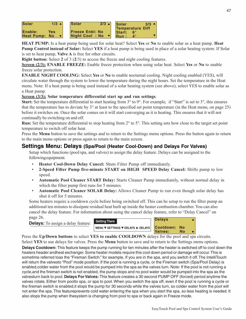
47
EasyTouch Pool and Spa Control System User’s Guide
Settings Menu: Delays (Spa/Pool (Heater Cool-Down) and Delays For Valves)Setup which functions (pool/spa, and valves) to assign the delay feature. Delays can be assigned to thefollowing equipment.
• Heater Cool-Down Delay Cancel: Shuts Filter Pump off immediately.• 2-Speed Filter Pump five-minute START on HIGH SPEED Delay Cancel: Shifts pump to low
speed.• Automatic Pool Cleaner START Delay: Starts Cleaner Pump immediately, without normal delay in
which the filter pump first runs for 5 minutes.• Automatic Pool Cleaner SOLAR Delay: Allows Cleaner Pump to run even though solar delay has
shut it off for 5 minutes.Some heaters require a cooldown cycle before being switched off. This can be setup to run the filter pump anadditional ten minutes to dissipate residual heat built up inside the heater combustion chamber. You can alsocancel the delay feature. For information about using the cancel delay feature, refer to “Delay Cancel” onpage 26.
Delays
Cooldown: NoValves: No
MENU ▼ SETTINGS ▼ DELAYS DELAYS
Getting There
▲
Solar 1/3
Enable: YesHeat Pump: No
Solar 3/3Temperature DiffStart: 6°Run : 4°
Solar 2/3
Freeze Enbl: NoNight Cool : No
Press the Up/Down buttons to select YES to enable COOLDOWN delays for the pool and spa circuits.Select YES to use delays for valves. Press the Menu button to save and to return to the Settings menu options.
HEAT PUMP: Is a heat pump being used for solar heat? Select Yes or No to enable solar as a heat pump. HeatPump Control instead of Solar: Select YES if a heat pump is being used in place of a solar heating system. If Solaris set to heat pump, Valve A is free for other circuits.Right button: Select 2 of 3 (2/3) to access the freeze and night cooling features.Screen (2/3): ENABLE FREEZE: Enable freeze protection when using solar heat. Select Yes or No to enablefreeze solar protection.ENABLE NIGHT COOLING: Select Yes or No to enable nocturnal cooling. Night cooling enabled (YES), willcirculate water through the system to lower the temperature during the night hours. Set the temperature in the Heatmenu. Note: If a heat pump is being used instead of a solar heating system (see above), select YES to enable solar asa Heat pump.Screen (3/3): Solar temperature differential start up and run settings.Start: Set the temperature differential to start heating from 3° to 9°. For example, if “Start” is set to 3°, this ensuresthat the temperature has to deviate by 3° at least to the specified set point temperature (in the Heat menu, on page 25)before it switches on. Once the solar comes on it will start converging as it is heating. This ensures that it will notcontinually be switching on and off.Run: Set the temperature differential to stop heating from 2° to 5°. This setting sets how close to the target set pointtemperature to switch off solar heat.Press the Menu button to save the settings and to return to the Settings menu options. Press the button again to returnto the main menu options or press again to return to the main screen.
Delays: To assign a delay feature:
Delays Cooldown: This feature keeps the pump running for ten minutes after the heater is switched off to cool down theheaters header andheat exchanger. Some heater models require this cool down period or damage will occur. This issometime referred toas the “Fireman Switch.” for example, If you are in the spa, and you switch it off. The IntelliTouchwill return the valvesto “Pool” mode position. If the pool is running a cycle, or the Fireman switch (Spa/Pool Delay) isenabled,colder water from the pool would be pumped into the spa as the valves turn. Note: If the pool is not running acycle,and the fireman switch is not enabled, the pump stops and no pool water would be pumped into the spa as thevalvesturn back to pool. Delays For Valves: This feature creates a 30 second PUMP OFF (forced) period anytime thevalves rotate. Either from poolto spa, or spa to pool. When you switch the spa off, even if the pool is running a cycle orthe fireman switch is enabled,it stops the pump for 30 seconds while the valves turn, so colder water from the pool willnot enter the spa. This featureprevents cold water entering the spa when you start the spa, so less heating is needed. Italso stops the pump when thesystem is changing from pool to spa or back again in Freeze mode.
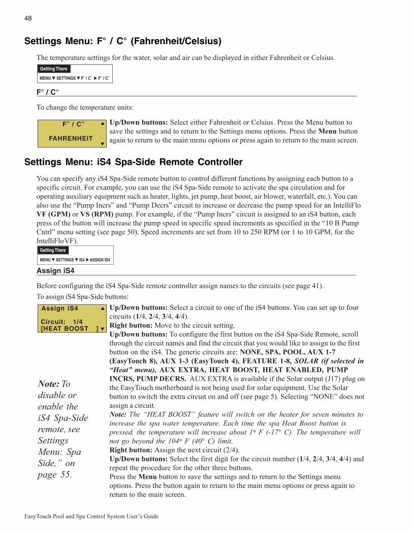
48
EasyTouch Pool and Spa Control System User’s Guide
Settings Menu: F° / C° (Fahrenheit/Celsius)
The temperature settings for the water, solar and air can be displayed in either Fahrenheit or Celsius.
F° / C°
To change the temperature units:
Up/Down buttons: Select either Fahrenheit or Celsius. Press the Menu button tosave the settings and to return to the Settings menu options. Press the Menu buttonagain to return to the main menu options or press again to return to the main screen.
Settings Menu: iS4 Spa-Side Remote Controller
You can specify any iS4 Spa-Side remote button to control different functions by assigning each button to aspecific circuit. For example, you can use the iS4 Spa-Side remote to activate the spa circulation and foroperating auxiliary equipment such as heater, lights, jet pump, heat boost, air blower, waterfall, etc.). You canalso use the “Pump Incrs” and “Pump Decrs” circuit to increase or decrease the pump speed for an IntelliFloVF (GPM) or VS (RPM) pump. For example, if the “Pump Incrs” circuit is assigned to an iS4 button, eachpress of the button will increase the pump speed in specific speed increments as specified in the “10 B PumpCntrl” menu setting (see page 50). Speed increments are set from 10 to 250 RPM (or 1 to 10 GPM, for theIntelliFlo VF).
Assign iS4
Before configuring the iS4 Spa-Side remote controller assign names to the circuits (see page 41).
To assign iS4 Spa-Side buttons:
Up/Down buttons: Select a circuit to one of the iS4 buttons. You can set up to fourcircuits (1/4, 2/4, 3/4, 4/4).Right button: Move to the circuit setting.Up/Down buttons: To configure the first button on the iS4 Spa-Side Remote, scrollthrough the circuit names and find the circuit that you would like to assign to the firstbutton on the iS4. The generic circuits are: NONE, SPA, POOL, AUX 1-7(EasyTouch 8), AUX 1-3 (EasyTouch 4), FEATURE 1-8, SOLAR (if selected in“Heat” menu), AUX EXTRA, HEAT BOOST, HEAT ENABLED, PUMPINCRS, PUMP DECRS. AUX EXTRA is available if the Solar output (J17) plug onthe EasyTouch motherboard is not being used for solar equipment. Use the Solarbutton to switch the extra circuit on and off (see page 5). Selecting “NONE” does notassign a circuit.Note: The “HEAT BOOST” feature will switch on the heater for seven minutes toincrease the spa water temperature. Each time the spa Heat Boost button ispressed, the temperature will increase about 1° F (-17° C). The temperature willnot go beyond the 104° F (40° C) limit.Right button: Assign the next circuit (2/4).Up/Down buttons: Select the first digit for the circuit number (1/4, 2/4, 3/4, 4/4) andrepeat the procedure for the other three buttons.Press the Menu button to save the settings and to return to the Settings menuoptions. Press the button again to return to the main menu options or press again toreturn to the main screen.
MENU ▼ SETTINGS ▼ IS4 ASSIGN IS4
Getting There
▲
F° / C°
FAHRENHEIT
MENU ▼ SETTINGS ▼ F˚ / C˚ F˚ / C˚
Getting There
▲
Assign iS4
Circuit: 1/4 [HEAT BOOST ]
Note: Todisable orenable theiS4 Spa-Sideremote, seeSettingsMenu: SpaSide,” onpage 55.

49
EasyTouch Pool and Spa Control System User’s Guide
Settings Menu: 10 Button Spa-Side Remote ControllerFrom this menu you can assigning a specific circuit to any one of the ten buttons of an iS10 and SpaCommandspa-side remote to control different pool/spa functions. The iS10 and SpaCommand has ten assignable circuitbuttons; five button on the top row and five buttons on the bottom row. You can also use the “Pump Incrs” and“Pump Decrs” circuit to increase or decrease the pump speed for an IntelliFlo VF (GPM), VS (RPM) andVSF (RPM/GPM) pump. For example, if the “Pump Incrs” circuit is assigned to an iS10 button, each press ofthe button will increase the pump speed in specific speed increments as specified in the “10B Pump Cntrl”menu setting (see page 50). Speed increments are set from 10 to 250 RPM (or 1 to 10 GPM, for the IntelliFloVF).Assign 10 Button Spa Side Remote (iS10/SpaCommand)
Before configuring the 10 button spa-side remote controller (iS10/SpaCommand) assign names to the circuits(see page 41).
To assign an iS10 and SpaCommand spa-side remote buttons:
Up/Down buttons: Select the “Top” or Bottom” row to assign circuits to.Right buttons: Select a circuit to one of the iS10 buttons. Five top row buttons canbe assigned circuits (1/5, 2/5, 3/5, 4/5 and 5/5). See “iS10/SpaCommand buttonassignments” below for details.Right button: Move to the circuit setting.Up/Down buttons: To configure the first button on the iS10 Spa-Side Remote, scrollthrough the circuit names and find the circuit that you would like to assign to the firstbutton on the iS4. The generic circuits are: NONE, SPA, POOL, AUX 1-7(EasyTouch 8), AUX 1-3 (EasyTouch 4), FEATURE 1-8, AUX EXTRA (orSOLAR if selected in “Heat” menu), HEAT BOOST and HEAT ENABLED.“Aux Extra” is displayed only available if the Solar output (J17) plug on theEasyTouch motherboard is not being used for solar equipment. Use the Solar button toswitch the extra circuit on and off (see page 5). Selecting “None” does not assign acircuit.Note: The “Heat Boost” feature will switch on the heater for seven minutes toincrease the spa water temperature. Each time the spa Heat Boost button ispressed, the temperature will increase about 1° F. The temperature will not gobeyond the 104° F (40° C) limit.Right button: Assign the next circuit (2/5).Up/Down buttons: Select the first digit for the circuit number (1/5, 2/5, 3/5, 4/5) andrepeat the procedure for the other three buttons.Press the Menu button to save the settings and to return to the Settings menuoptions. Press the button twice to return to the main screen.
MENU ▼ SETTINGS ▼ 10 BUTN SPA SD ASSIGN 10 BUTN
Getting There
▲
1nottuBAPS LOOP
PMET-IH PMET-OL
2nottuB 1XUA 5XUA
3nottuB 2XUA 6XUA
4nottuB 3XUA 7XUA
5nottuB 4XUA 8XUA
iS10 and SpaCommand button assignments
Assign 10 BtnSSRow : TopCircuit : 1/5[SPA ]
IS410 BUTN SPA SD10B Pump CntrlQuick Touch
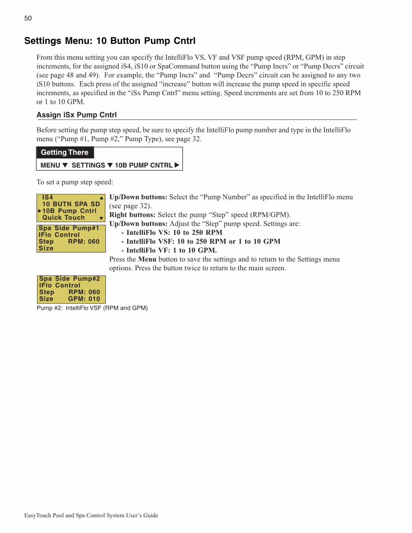
50
EasyTouch Pool and Spa Control System User’s Guide
Settings Menu: 10 Button Pump Cntrl
From this menu setting you can specify the IntelliFlo VS, VF and VSF pump speed (RPM, GPM) in stepincrements, for the assigned iS4, iS10 or SpaCommand button using the “Pump Incrs” or “Pump Decrs” circuit(see page 48 and 49). For example, the “Pump Incrs” and “Pump Decrs” circuit can be assigned to any twoiS10 buttons. Each press of the assigned “increase” button will increase the pump speed in specific speedincrements, as specified in the “iSx Pump Cntrl” menu setting. Speed increments are set from 10 to 250 RPMor 1 to 10 GPM.
Assign iSx Pump Cntrl
Before setting the pump step speed, be sure to specify the IntelliFlo pump number and type in the IntelliFlomenu (“Pump #1, Pump #2,” Pump Type), see page 32.
To set a pump step speed:
Up/Down buttons: Select the “Pump Number” as specified in the IntelliFlo menu(see page 32).Right buttons: Select the pump “Step” speed (RPM/GPM).Up/Down buttons: Adjust the “Step” pump speed. Settings are:
- IntelliFlo VS: 10 to 250 RPM- IntelliFlo VSF: 10 to 250 RPM or 1 to 10 GPM- IntelliFlo VF: 1 to 10 GPM.
Press the Menu button to save the settings and to return to the Settings menuoptions. Press the button twice to return to the main screen.
MENU ▼ SETTINGS ▼ 10B PUMP CNTRL
Getting There
▲
Spa Side Pump#1IFlo ControlStep RPM: 060Size
Spa Side Pump#2IFlo ControlStep RPM: 060Size GPM: 010
IS410 BUTN SPA SD10B Pump CntrlQuick Touch
Pump #2: IntelliFlo VSF (RPM and GPM)
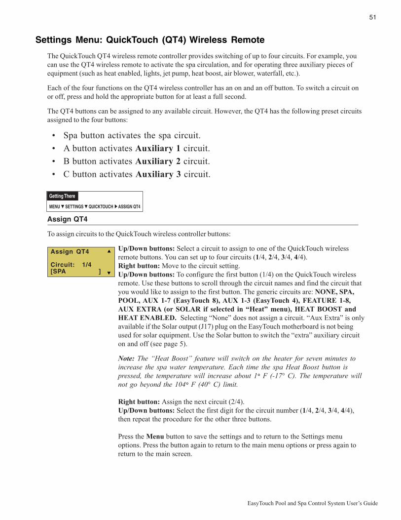
51
EasyTouch Pool and Spa Control System User’s Guide
Settings Menu: QuickTouch (QT4) Wireless Remote
The QuickTouch QT4 wireless remote controller provides switching of up to four circuits. For example, youcan use the QT4 wireless remote to activate the spa circulation, and for operating three auxiliary pieces ofequipment (such as heat enabled, lights, jet pump, heat boost, air blower, waterfall, etc.).
Each of the four functions on the QT4 wireless controller has an on and an off button. To switch a circuit onor off, press and hold the appropriate button for at least a full second.
The QT4 buttons can be assigned to any available circuit. However, the QT4 has the following preset circuitsassigned to the four buttons:
• Spa button activates the spa circuit.
• A button activates Auxiliary 1 circuit.
• B button activates Auxiliary 2 circuit.
• C button activates Auxiliary 3 circuit.
Assign QT4
To assign circuits to the QuickTouch wireless controller buttons:
Up/Down buttons: Select a circuit to assign to one of the QuickTouch wirelessremote buttons. You can set up to four circuits (1/4, 2/4, 3/4, 4/4).Right button: Move to the circuit setting.Up/Down buttons: To configure the first button (1/4) on the QuickTouch wirelessremote. Use these buttons to scroll through the circuit names and find the circuit thatyou would like to assign to the first button. The generic circuits are: NONE, SPA,POOL, AUX 1-7 (EasyTouch 8), AUX 1-3 (EasyTouch 4), FEATURE 1-8,AUX EXTRA (or SOLAR if selected in “Heat” menu), HEAT BOOST andHEAT ENABLED. Selecting “None” does not assign a circuit. “Aux Extra” is onlyavailable if the Solar output (J17) plug on the EasyTouch motherboard is not beingused for solar equipment. Use the Solar button to switch the “extra” auxiliary circuiton and off (see page 5).
Note: The “Heat Boost” feature will switch on the heater for seven minutes toincrease the spa water temperature. Each time the spa Heat Boost button ispressed, the temperature will increase about 1° F (-17° C). The temperature willnot go beyond the 104° F (40° C) limit.
Right button: Assign the next circuit (2/4).Up/Down buttons: Select the first digit for the circuit number (1/4, 2/4, 3/4, 4/4),then repeat the procedure for the other three buttons.
Press the Menu button to save the settings and to return to the Settings menuoptions. Press the button again to return to the main menu options or press again toreturn to the main screen.
MENU ▼ SETTINGS ▼ QUICKTOUCH ASSIGN QT4
Getting There
▲
Assign QT4
Circuit: 1/4[SPA ]

52
EasyTouch Pool and Spa Control System User’s Guide
Settings Menu: Man Heat (Off/On)
By default manual heat (Man Heat) is set to “On,” which allows your spa to begin to heat whenever it ismanually switched on, (by pressing the Valves (V) button and Filter Pump (F) button on the outdoor controlpanel or the Spa button on the Indoor Control Panel), even if the Heat menu setting is set to “OFF” (see page25). Your spa will also begin to heat when switched on by the iS4 Spa-Side remote. This feature allows you toprogram your spa to filter daily with the heater set to off, and then be ready to heat whenever the Spa button ispressed manually.
Man HeatTo enable or disable spa manual heat when switched on manually:
Right button:: Select Off to disable or On to automatically begin spa heatingwhenever the spa is switched on manually.Press the Menu button to save the settings and to return to the main screen.
Settings Menu: Calibration
The EasyTouch system includes two temperature sensors (10 kΩ) for water and ambient air temperature. Youcan also add an additional sensor for controlling solar heating systems. Generally, these sensors are accurateand you do not have to calibrate them. However, long plumbing runs and water features can causetemperatures at a body of water to be different from the temperature sensor reading. You can manuallyrecalibrate the sensors to adjust for this. You only need to calibrate one body of water, since the temperaturesensor is common to both the pool and spa. The system must be in “Service” mode to calibrate sensors.
Calibration
Before you start, you need an accurate all weather thermometer. If you are calibrating the air sensor, wait untilthe sensor is not in direct sunlight. For the air temperature sensor, make sure that the sensor is located in theshade for accurate readings.
To calibrate the water, air and solar temperature sensors:
1. Press the Mode button on the control panel to place the system in “Service” manual mode.2. Press the Filter Pump (F) button to switch on the pool/spa filter pump.3. Place the thermometer in the spa or pool water. Take an accurate temperature reading. When
calibrating the air sensor, place the thermometer next to the air sensor. The air sensor is normallylocated near or under the EasyTouch load center enclosure, not inside the enclosure. Take anaccurate temperature reading in the shade.
4. Use the Up or Down buttons to raise or lower the water temperature tomatch the corresponding thermometer temperature reading.
5. After calibrating the water sensor, use the Right button to move to the“AIR” setting and repeat step 4 and repeat the procedure for the solarsensor. Ensure that the solar sensor is in the sun for accurate readings.
6. After calibrating all the sensors, press the Menu button to save the settings and to return to theSettings menu options. Press the button again to return to the main menu options or press again toreturn to the main screen.
MENU ▼ SETTINGS ▼ CALIBRATION CALIBRATION
Getting There
▲
CalibrationWater: 70°FAir: 80°FSolar: 90°F
10B Pump CntrlQuickTouchMan Heat [On]Calibration
MENU ▼ SETTINGS ▼ MAN HEAT [On/Off]
Getting There
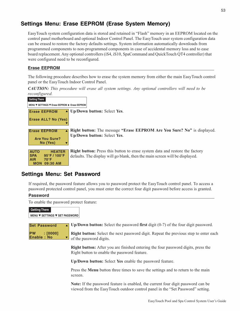
53
EasyTouch Pool and Spa Control System User’s Guide
Settings Menu: Set Password
If required, the password feature allows you to password protect the EasyTouch control panel. To access apassword protected control panel, you must enter the correct four digit password before access is granted.
Password
To enable the password protect feature:
Up/Down button: Select the password first digit (0-7) of the four digit password.
Right button: Select the next password digit. Repeat the previous step to enter eachof the password digits.
Right button: After you are finished entering the four password digits, press theRight button to enable the password feature.
Up/Down button: Select Yes enable the password feature.
Press the Menu button three times to save the settings and to return to the mainscreen.
Note: If the password feature is enabled, the current four digit password can beviewed from the EasyTouch outdoor control panel in the “Set Password” setting.
MENU ▼ SETTINGS ▼ SET PASSWORD
Getting There
Set Password
PW : [0000]Enable : No
Settings Menu: Erase EEPROM (Erase System Memory)
EasyTouch system configuration data is stored and retained in “Flash” memory in an EEPROM located on thecontrol panel motherboard and optional Indoor Control Panel. The EasyTouch user system configuration datacan be erased to restore the factory defaults settings. System information automatically downloads fromprogrammed components to non-programmed components in case of accidental memory loss and to easeboard replacement. Any optional controllers (iS4, iS10, SpaCommand and QuickTouch QT4 controller) thatwere configured need to be reconfigured.
Erase EEPROM
The following procedure describes how to erase the system memory from either the main EasyTouch controlpanel or the EasyTouch Indoor Control Panel.
CAUTION: This procedure will erase all system settings. Any optional controllers will need to bereconfigured.
Up/Down button: Select Yes.
Right button: The message “Erase EEPROM Are You Sure? No” is displayed.Up/Down button: Select Yes.
Right button: Press this button to erase system data and restore the factorydefaults. The display will go blank, then the main screen will be displayed.
MENU ▼ SETTINGS ▼ Erase EEPROM Erase EEPROM
Getting There
▲
Erase EEPROM
Erase ALL? No (Yes)
Erase EEPROM
Are You Sure? No (Yes)
AUTO HEATERSPA 95°F / 100°FAIR 70°F MON 09:30 AM
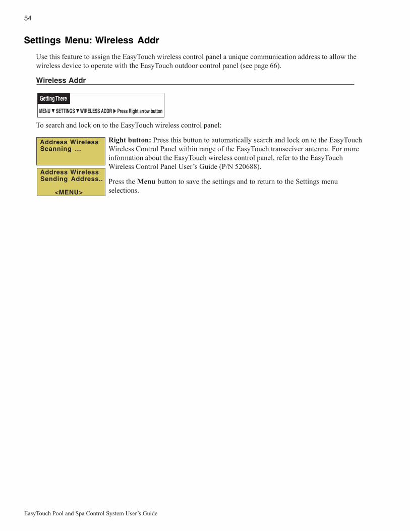
54
EasyTouch Pool and Spa Control System User’s Guide
Address Wireless Sending Address..
<MENU>
Address Wireless Scanning ...
MENU ▼ SETTINGS ▼ WIRELESS ADDR Press Right arrow button
Getting There
▲
Settings Menu: Wireless Addr
Use this feature to assign the EasyTouch wireless control panel a unique communication address to allow thewireless device to operate with the EasyTouch outdoor control panel (see page 66).
Wireless Addr
To search and lock on to the EasyTouch wireless control panel:
Right button: Press this button to automatically search and lock on to the EasyTouchWireless Control Panel within range of the EasyTouch transceiver antenna. For moreinformation about the EasyTouch wireless control panel, refer to the EasyTouchWireless Control Panel User’s Guide (P/N 520688).
Press the Menu button to save the settings and to return to the Settings menuselections.

55
EasyTouch Pool and Spa Control System User’s Guide
Spa Side [Off/On]
Enable or disable the iS4 Spa Side remote. This feature is useful for families with young children or when yougo on vacation. It allows you to switch off the iS4 Spa Side remote at the control panel so that the remotecannot be used.
Spa Side
To enable or disable the iS4 Spa Side remote:
Right button: Select On or Off to enable or disable the spa side remote.Press the Menu button to save the settings and to return to the main screen.
Diagnostics Menu: Software Rev
Displays the current software revision for the EasyTouch main control panel and the optional indoor controlpanel.
UIC: Displays the current software revision level for the indoor control panel.UOC: Displays the current software revision level for the outdoor control panel.Press the Menu button to return to the Settings menu options. Press the button againto return to the main menu options or press again to return to the main screen.
Diagnostics Menu: Bootloader Rev
Displays the current bootloader revision for the indoor control panel and the main EasyTouch control panel.
UIC: Displays the current bootloader revision level for the indoor control panel.UOC: Displays the current bootloader revision level for the outdoor control panel.Press the Menu button to return to the Settings menu options. Press the button againto return to the main menu options or press again to return to the main screen.
MENU ▼ DIAGNOSTICS ▼ SOFTWARE REV
Getting There
MENU ▼ DIAGNOSTICS ▼ BOOTLOADER REV
Getting There
Bootloader Rev
UIC: 1.02 UOC: 1.02
Software Rev
UIC: 1.02 UOC: 1.02
MENU ▼ SPA SIDE [On/Off]
Getting There
Delay CancelSchedulesSettingsSpa Side [On ]

56
EasyTouch Pool and Spa Control System User’s Guide
Diagnostics Menu: Self TestTests the control panel LCD and buttons. Follow the on-screen prompts to perform the tests.
Note: If the Indoor Control Panel is connected to the EasyTouch outdoor control panel, select “LINKCLOSED” in the UART test to abort the UART test. This allows the test to complete with and displayPASSED.
Press the Right button to display the current software and boot loader revision levelsfor the EasyTouch outdoor control panel.Press the Right button to start the test:Press the Right button to start the test:
Display Test: Press any button to start the LCD test.
Backlight Test: Press the Left then Right button.
Contrast Test: Press any button to continue.
LED Test: Press any button to continue. All of the button LEDs will be tested.
Switch Test: Press any button to continue. As prompted, press the appropriatebuttons.
UART Test: Select “LINK CLOSED” to abort this test if the optional IndoorControl Panel is connected to the EasyTouch load center.
Status: Passed - Code 0: After you have completed the test an error code isdisplayed. “Passed” is displayed if the test was successful. For error codedescriptions, see “Self Test Error Codes,” on page 60.
Press the Menu button to return to the Settings menu options. Press the button againto return to the main menu options or press again to return to the main screen.
MENU ▼ DIAGNOSTICS ▼ SELF TEST
Getting There
Backlight On<=Backlight On>=Backlight Off
Contrast:
Press any button
LED Test
Switch Test
Press any button
UART Test<=Link Closed>=Link Open
Press Any Button
Firmware VersionSoft: 1.02Boot: 1.02Press Any Button
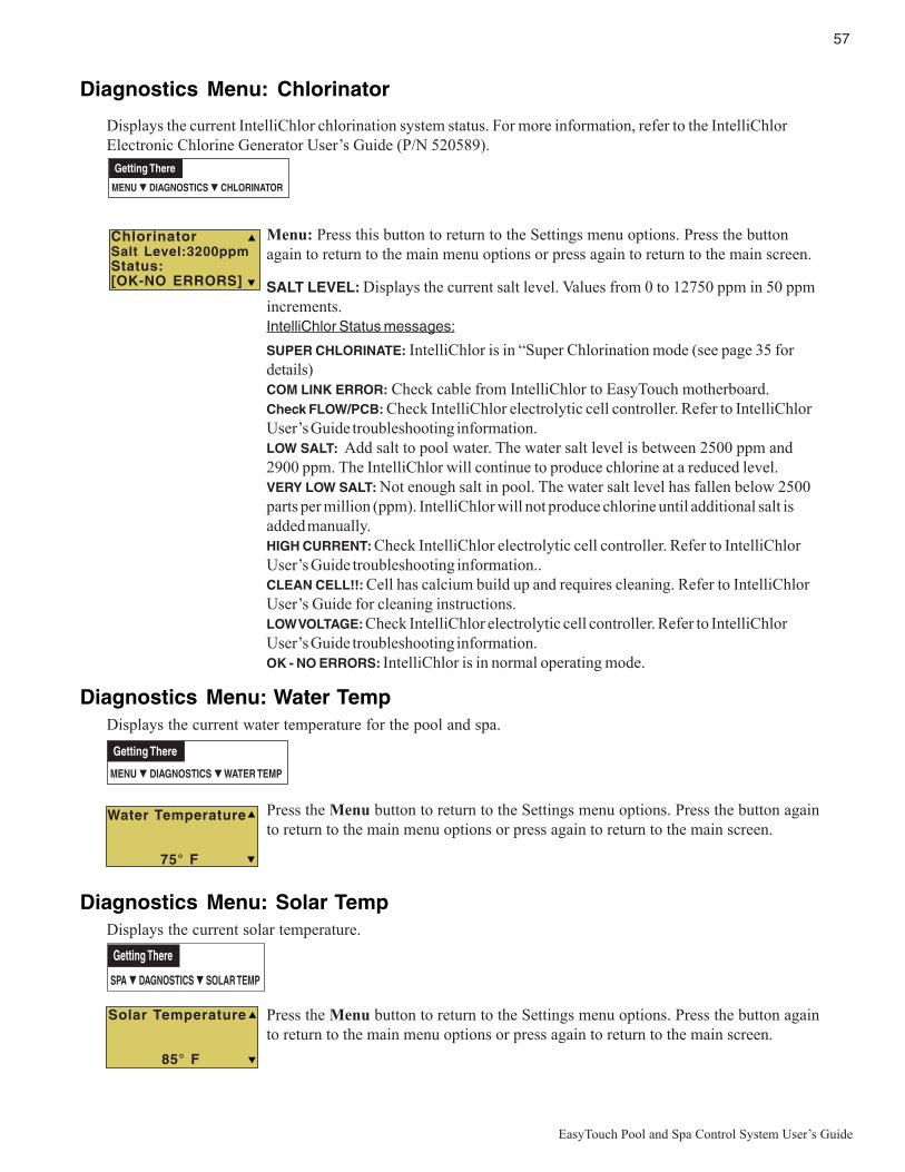
57
EasyTouch Pool and Spa Control System User’s Guide
Diagnostics Menu: Chlorinator
Displays the current IntelliChlor chlorination system status. For more information, refer to the IntelliChlorElectronic Chlorine Generator User’s Guide (P/N 520589).
Menu: Press this button to return to the Settings menu options. Press the buttonagain to return to the main menu options or press again to return to the main screen.
SALT LEVEL: Displays the current salt level. Values from 0 to 12750 ppm in 50 ppmincrements.IntelliChlor Status messages:
SUPER CHLORINATE: IntelliChlor is in “Super Chlorination mode (see page 35 fordetails)COM LINK ERROR: Check cable from IntelliChlor to EasyTouch motherboard.Check FLOW/PCB: Check IntelliChlor electrolytic cell controller. Refer to IntelliChlorUser’s Guide troubleshooting information.LOW SALT: Add salt to pool water. The water salt level is between 2500 ppm and2900 ppm. The IntelliChlor will continue to produce chlorine at a reduced level.VERY LOW SALT: Not enough salt in pool. The water salt level has fallen below 2500parts per million (ppm). IntelliChlor will not produce chlorine until additional salt isadded manually.HIGH CURRENT: Check IntelliChlor electrolytic cell controller. Refer to IntelliChlorUser’s Guide troubleshooting information..CLEAN CELL!!: Cell has calcium build up and requires cleaning. Refer to IntelliChlorUser’s Guide for cleaning instructions.LOW VOLTAGE: Check IntelliChlor electrolytic cell controller. Refer to IntelliChlorUser’s Guide troubleshooting information.OK - NO ERRORS: IntelliChlor is in normal operating mode.
Diagnostics Menu: Water TempDisplays the current water temperature for the pool and spa.
Press the Menu button to return to the Settings menu options. Press the button againto return to the main menu options or press again to return to the main screen.
Diagnostics Menu: Solar TempDisplays the current solar temperature.
Press the Menu button to return to the Settings menu options. Press the button againto return to the main menu options or press again to return to the main screen.
MENU ▼ DIAGNOSTICS ▼ WATER TEMP
Getting There
SPA ▼ DAGNOSTICS ▼ SOLAR TEMP
Getting There
MENU ▼ DIAGNOSTICS ▼ CHLORINATOR
Getting There
ChlorinatorSalt Level:3200ppmStatus:[OK-NO ERRORS]
Solar Temperature
85° F
Water Temperature
75° F
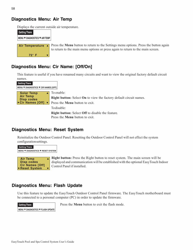
58
EasyTouch Pool and Spa Control System User’s Guide
Diagnostics Menu: Reset System
Reinitialize the Outdoor Control Panel. Resetting the Outdoor Control Panel will not effect the systemconfiguration settings.
Right button: Press the Right button to reset system. The main screen will bedisplayed and communication will be established with the optional EasyTouch IndoorControl Panel if installed.
Diagnostics Menu: Flash Update
Use this feature to update the EasyTouch Outdoor Control Panel firmware. The EasyTouch motherboard mustbe connected to a personal computer (PC) in order to update the firmware.
Press the Menu button to exit the flash mode.
Air Temp Disp codes Cir Names [Off] Reset System
MENU ▼ DIAGNOSTICS ▼ RESET SYSTEM
Getting There
MENU ▼ DIAGNOSTICS ▼ FLASH UPDATE
Getting There
Diagnostics Menu: Air Temp
Displays the current outside air temperature.
Press the Menu button to return to the Settings menu options. Press the button againto return to the main menu options or press again to return to the main screen.
Diagnostics Menu: Cir Name: [Off/On]
This feature is useful if you have renamed many circuits and want to view the original factory default circuitnames.
To enable:
Right button: Select On to view the factory default circuit names.
Press the Menu button to exit.
To disable:
Right button: Select Off to disable the feature.Press the Menu button to exit.
MENU ▼ DIAGNOSTICS ▼ AIR TEMP
Getting There
Air Temperature
72° F
Solar Temp Air Temp Disp codes Cir Names [Off]
MENU ▼ DIAGNOSTICS ▼ CIR NAMES [OFF]
Getting There
59
EasyTouch Pool and Spa Control System User’s Guide
Section 3Troubleshooting
Troubleshooting
Use the following troubleshooting information to help resolve problems that may occur when using theEasyTouch system. If by following the recommended actions you are still unable to resolve the problems,please contact Technical Support (see page vi).
Frequently Asked Questions (FAQ)
How do I setup a two-speed pump?
A two-speed pump operates using two relays and one or more circuits. The first relay turns the pump on oroff. Assuming this is a filter pump, this circuit is controlled by the pool and spa circuits or any other circuit thatmay be tied to the filter pump (such as circuits with freeze protection, etc.). The second relay switches thepump from low speed to high speed. The default condition is low speed. Up to seven circuits (EasyTouch 8),three circuits (EasyTouch 4) may be assigned to trigger the pump to high speed. Note: These circuits do notswitch the pump on.
To configure a two-speed pump relay, refer to “Settings Menu: 2-Speed Pump,” on page 46. For relay locationand wiring (see page 64). The 2-Speed pump relay connector is plugged into the 2-SPD output on theEasyTouch motherboard.
Can I switch the heater on and change the temperature from the spa?
The heater may be switched on from the spa location using the iS4 Spa-Side remote or by the QuickTouchwireless remote controller. To learn more about these remotes and controllers, see page 6. However, the iS4and QuickTouch wireless remote controller cannot adjust the water temperature.
How do I switch on solar heating?
The system must first be configured for solar heating. Go to the “Heat” menu (see page 25) and enable“Solar” as the heat source (Settings Menu: Heat > Solar). Note: Do not set solar as a heat pump. Then theheating method must be selected for each body of water.

60
EasyTouch Pool and Spa Control System User’s Guide
egasseMrorrE esuaCelbissoP noituloS
niaMehtnosyalpsiD(rrEriA)neercS
detcennoctonrosnesriAhcuoTysaEehtot
.draobrehtom
12JotdetcennocsigulprosnesriaehttahtkcehCrosnesehttahtkcehC.draobrehtomehtnorotcennoc
.ylreporpdetcennocsieriw
nisyalpsiD(rrEerutarepmeTriA)unem"scitsongaiD"eht
detcennoctonrosnesriAhcuoTysaEehtot
.draobrehtom
12JotdetcennocsigulprosnesriaehttahtkcehC.draobrehtomehtnorotcennoc
syalpsiD(rrEerutarepmeTretaW)unem"scitsongaiD"ehtni
tonrosnesretaWehtotdetcennoc
.draobrehtomhcuoTysaE
12JotdetcennocsigulprosnesretawehttahtkcehC.draobrehtomehtnorotcennoc
syalpsiD(rrEerutarepmeTraloS)unem"scitsongaiD"ehtni
tonrosnesraloSehtotdetcennoc
.draobrehtomhcuoTysaE
12JotdetcennocsigulprosnesralosehttahtkcehC.draobrehtomehtnorotcennoc
Self Test Error Codes
The “Self Test” feature is intended for use by service personnel. If after performing a control panel self test(see page 56) there were no errors detected, Code 0 is displayed, indicating that there were no problems andthe test was successful. If a problem is detected during the test, an error code is displayed upon completion ofthe test. For example Code 3 would indicate a problem with the LEDs on the control panel. If multiple errorsare detected, multiple code numbers are displayed. For example, Codes 4, 2, 1, would indicate problemsdetected with the buttons, LEDs, and the LCD backlight on the control panel.
The following lists the control panel self test error codes.
Error Code Table
EasyTouch Error Messages
Error Messages
If the system detects that a sensor is not connected to the EasyTouch load center or it is defective, an errormessage is displayed in the “Diagnostics” menu. The following lists the sensor errors.
edoCrorrE noitpircseD
0edoC sahlenaplortnocehT-SSAPsmelborpon
1edoC thgilkcabDCL
2edoC tsartnocDCL
3edoC sDEL
4edoC )snottub(hctiwS
5edoC tsetkcabpoolTRAU
6edoC tsetsevlaV/yaleR/rosneS

61
EasyTouch Pool and Spa Control System User’s Guide
egasseMsutatS esuaCelbissoP noituloS
SRORREON-KO lamronrolhCilletnI.edomgnitarepo
A/N
ETANIROLHCREPUS repuS"nisirolhCilletnI42rofedom"noitanirolhC
.sruoh
73egapees(edomnoitanirolhCrepuS“nisirolhCilletnI)sliatedro
RORREKNILMOC noitacinummocrolhCilletnIhcuoTysaEhtiwrorre
.draobrehtom
.draobrehtomhcuoTysaEotrolhCilletnImorfelbackcehC
BCP/WOLFKCEHC rolhCilletnIkcehC.lleccitylortcele
gnitoohselbuortediuGs’resUrolhCilletnIotrefeR.noitamrofni
TLASWOL .retawloopottlasddA .mpp0092dnampp0052neewtebsileveltlasretawehTataenirolhcecudorpoteunitnoclliwrolhCilletnIehT
.sliatedrofediuGs'resUrolhCilletnIeeS.leveldecuder
TLASWOLYREV .loopnitlashguonetoN repstrap0052wolebnellafsahleveltlasretawehTlitnuenirolhcecudorptonlliwrolhCilletnI.)mpp(noillims'resUrolhCilletnIeeS.yllaunamdeddasitlaslanoitidda
.sliatedrofediuG
TNERRUCHGIH rolhCilletnIkcehC.lleccitylortcele
otrefeR.rellortnoclleccitylortcelerolhCilletnIkcehC.noitamrofnignitoohselbuortediuGs’resUrolhCilletnI
!!LLECNAELC pudliubmuiclacsahlleC.gninaelcseriuqerdna
otrefeR.gninaelcseriuqerdnapudliubmuiclacsahlleC.snoitcurtsnigninaelcrofediuGs’resUrolhCilletnI
EGATLOVWOL rolhCilletnIkcehC.lleccitylortcele
gnitoohselbuortediuGs’resUrolhCilletnIotrefeR.noitamrofni
Maximum Programs Exceeded
The “Maximum Programs Exceeded” message displays in the “Schedules” menu if you try to create a newprogram after exceeding the 12 program limit. To create a new program you must first delete an existingprogram. For information about deleting a program, refer to “Schedule Menu” on page 27.
IntelliChlor Error Messages
IntelliChlor status and error messages are displayed in the “Chlorinator” menu (see page 37). Use thefollowing information to resolve IntelliChlor system problems. To access the IntelliChlor menu, pressMenu > Diagnostics > Chlorinator.
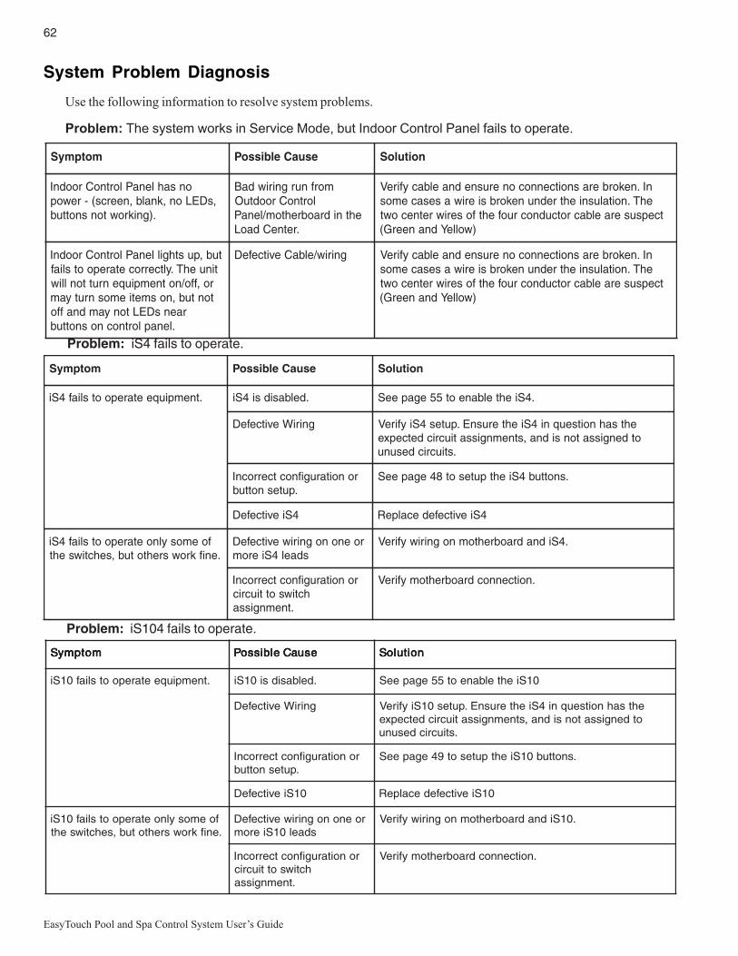
62
EasyTouch Pool and Spa Control System User’s Guide
Problem: iS4 fails to operate.
motpmyS esuaCelbissoP noituloS
.tnempiuqeetarepootsliaf4Si .delbasidsi4Si .4Siehtelbaneot55egapeeS
gniriWevitcefeD ehtsahnoitseuqni4SiehterusnE.putes4SiyfireVotdengissatonsidna,stnemngissatiucricdetcepxe
.stiucricdesunu
ronoitarugifnoctcerrocnI.putesnottub
.snottub4Siehtputesot84egapeeS
4SievitcefeD 4SievitcefedecalpeR
foemosylnoetarepootsliaf4Si.enifkrowsrehtotub,sehctiwseht
roenonogniriwevitcefeDsdael4Sierom
.4SidnadraobrehtomnogniriwyfireV
ronoitarugifnoctcerrocnIhctiwsottiucric
.tnemngissa
.noitcennocdraobrehtomyfireV
System Problem Diagnosis
Use the following information to resolve system problems.
Problem: The system works in Service Mode, but Indoor Control Panel fails to operate.
motpmyS esuaCelbissoP noituloS
onsahlenaPlortnoCroodnI,sDELon,knalb,neercs(-rewop
.)gnikrowtonsnottub
morfnurgniriwdaBlortnoCroodtuO
ehtnidraobrehtom/lenaP.retneCdaoL
nI.nekorberasnoitcennoconerusnednaelbacyfireVehT.noitalusniehtrednunekorbsieriwasesacemos
tcepsuseraelbacrotcudnocruofehtfoseriwretnecowt)wolleYdnaneerG(
tub,pusthgillenaPlortnoCroodnItinuehT.yltcerrocetarepootsliaf
ro,ffo/notnempiuqenruttonlliwtontub,nosmetiemosnrutyam
raensDELtonyamdnaffo.lenaplortnocnosnottub
gniriw/elbaCevitcefeD yfireV elbac nI.nekorberasnoitcennoconerusnednaehT.noitalusniehtrednunekorbsieriwasesacemos
tcepsuseraelbacrotcudnocruofehtfoseriwretnecowt)wolleYdnaneerG(
motpmyS motpmyS motpmyS motpmyS motpmyS esuaCelbissoP esuaCelbissoP esuaCelbissoP esuaCelbissoP esuaCelbissoP noituloS noituloS noituloS noituloS noituloS
.tnempiuqeetarepootsliaf01Si .delbasidsi01Si 01Siehtelbaneot55egapeeS
gniriWevitcefeD ehtsahnoitseuqni4SiehterusnE.putes01SiyfireVotdengissatonsidna,stnemngissatiucricdetcepxe
.stiucricdesunu
ronoitarugifnoctcerrocnI.putesnottub
.snottub01Siehtputesot94egapeeS
01SievitcefeD 01SievitcefedecalpeR
foemosylnoetarepootsliaf01Si.enifkrowsrehtotub,sehctiwseht
roenonogniriwevitcefeDsdael01Sierom
.01SidnadraobrehtomnogniriwyfireV
ronoitarugifnoctcerrocnIhctiwsottiucric
.tnemngissa
.noitcennocdraobrehtomyfireV
Problem: iS104 fails to operate.

63
EasyTouch Pool and Spa Control System User’s Guide
Problem: The Quick Touch remote will not work, or will not work dependably.
motpmyS esuaCelbissoP noituloS
nothgiltonseodDELREWOPehtnidetacoldraobrevieceReht
.llehsmalccitsalp
retneCdaoLhcuoTysaErewopevahtonseod
rewopehttahtdnadeilppusgniebsirewoperusnEdellatsnireviecerehttuohtiwyltcerrocsetareporetnec
roelbacevitcefeDdaoLehtotnoitcennoc
retneC
elbacdoognwonkgnisudraobehtfonoitcnufehtyfireVgniriwllakcehC.tes
draobrevieceRevitcefeD troppuSlacinhceTtcatnoC
thgiltonseodDELKNILMMOCDELnoitarepolamronnI.knilbrosdnoces2yrevetsaeltaknilblliw
roelbacevitcefeDdaoLehtotnoitcennoc
retneC
elbacdoognwonkgnisudraobehtfonoitcnufehtyfireVtes
draobreviecerevitcefeD draobreviecerecalpeR
yltcerrocnierasehctiwssserddAderugifnoc
sserddaehttahtyfireVehtnosehctiws
dlehdnahdnarettimsnarttcerroceradraobreviecer
hctamdna
deliafsahyrettabrettimsnarT
rettimsnarTecalpeRyrettab
revieceRrorettimsnarTevitcefeD
stiucricemostub,snoitcnuftinUehtetareporo,krowtonod
tiucrictcerrocni
noitarugifnochcuoTkciuQtcerrocnisi
snottubputesot15egapeeS
otsliafro,etarepootsliaftinUegnartaylbadnepedetarepo
esionlacirtceleevissecxE lacirtcele"ysion"morfyawareviecerehtetacoleRsrotomrewolbsahcustnempiuqe
snoitcurtsboynamooTrettimsnartehtneewteb
reviecerdna
dnalatemdnuorgmorfyawareviecerehtetacoleRsnoitcurtsbo
raenootsitinurevieceRdnuorgeht
neewtebecnatsidehtezimixamotreviecerehtetacoleRdnuorgehtdnaannetnareviecereht

64
EasyTouch Pool and Spa Control System User’s Guide
motpmyS esuaCelbissoP noituloS
fforononrutotsmeestinU/resuehttuohtiwstiucric
rettimsnart
siemohybraenAralimisagnitarepo
tinusseleriw
dnarettimsnartehtrofedocsserddaetanretlanatceleSdnareviecerhtobnosehctiwsehtegnahC.reviecer
.gnittesgnihctamtub,etanretlanaotetomer
tnempiuqesnrutylbadnepedtinUsitnempiuqeecnotub,NO
ylbadnepedtonseodtigninnursiegnarro,FFOtnempiuqenrut
tnempiuqenehwdecuderyltaerggninnursi
siesionlacirtceleeudnUroenoybdecudorpgniebtnempiuqefoseceiperom
ehtotytimixorpesolcni.reviecer
sahcustnempiuqemorfyawarevieceRehtetacoleRtahtnoitacolanireviecerehtetacoleR.srotomrewolb
resuehtaeraehtotsnoitcurtsborewefsedivorp.rettimsnartehtsetarepoylnommoc
yltaergsahtub,setarepotinUroirpotderapmocegnardecuder
noitcnuf
siyrettaBrettimsnarT.gniliaf
.)V32302epyt(yrettabrettimsnarTecalpeR
Problem: The Quick Touch remote will not work, or will not work dependably (Continued).
Indoor Control PanelRF TransceiveriS4 and iS10 Spa Side RemoteIntelliChlor
SOLAR BOOSTER PUMP/AUX EXTRA
QuickTouchIntelliFlo VF, IntelliFlo VS
EasyTouch System Wiring Diagram(Outdoor Control Panel)

65
EasyTouch Pool and Spa Control System User’s Guide
First Time System Start-Up
The following information describes a basic system start-up procedure. Before you power up the EasyTouchsystem at the Load Center first check the following:
Check Electronics
Check that the following plugs are seated correctly on the EasyTouch Load Center motherboard. Forconnector locations, refer to the EasyTouch System Wiring Diagram on page 64.
• Relay connectors - FLTR PUMP - AUX 1 - 7 (EasyTouch 8), AUX 1 - 3 (EasyTouch 4)• Temperature sensors connectors - WATER, SOLAR, AIR• Transformer wire harness - J1• Heater control connector - ELEC HTR and GAS HEATER (J19)
System Test
Follow the steps below to test the EasyTouch control panel to activate the heater, valves and pumps. This testassumes that all system equipment has been properly installed and connected to the EasyTouch Load center.
Testing Valve Actuators and Pumps:
Use the following steps to test the valve actuators (CVA24T) for proper rotation.
To test the valve actuators and pump:
1. Switch on the electrical power at the house breaker.
2. Switch on the EasyTouch Load Center. You may need to switch on the breakers on the Load Center.
3. Press the Mode button to enable “Service” mode.
4. Press the Valve (V) button to select “Pool” mode.
5. Press the Filter Pump (F) button to activate the filter pump. Water will be removed from the pooland returned to the pool. A spa bypass line divert a small amount of water to the spa. Make sure thefilter pump turns on correctly. If the pump has two speeds: Press the button one time to run the pumpin low speed. Press the button again to run the pump in high speed. Press the button again to switchthe pump off. A Two-Speed pump has to be configured in the 2-Speed menu (see page 46).
6. Set both valve actuators (CVA-24T) for suction and return. Use the toggle switch on the rear of theCVA-24T to withdraw and return water from the pool.
7. Press the Valves (V) button. Step through all four valve positions: Pool, Spa, Fill, Drain. Make surethe valves turn on correctly and the water is moving in the correct direction for each position. Ifnecessary, flip the actuator toggle switch to change the direction of the water.
Note: With the filter pump operating, if water is not being removed and returned to the pool,it may be necessary to reverse the RETURN with VLV A (or VLV B) plugs on the EasyTouchmotherboard.
Testing the Auxiliary Relays
Affix the auxiliary relay labels to the appropriate buttons on the EasyTouch control panel and/or theEasyTouch Indoor Control Panel. If necessary, write the function on the control panel.
1. Step through the rest of the auxiliary buttons. Notice which button turns on which equipment. Youmay need to walk the property to find what each button turns on.
2. Write down what each button switches on, including the number of the circuit. You need thisinformation when you set up the Indoor Control Panel.
3. Label the circuit buttons on the outdoor control panel and the EasyTouch Indoor Control Panel.

66
EasyTouch Pool and Spa Control System User’s Guide
Setting up the EasyTouch wireless control panel for the first time
Setting up the EasyTouch wireless control panelIn order for the EasyTouch wireless control panel to communicate with the EasyTouch system outdoor controlpanel, the first time the wireless device is powered up it must first be assigned a unique communicationaddress. For this process you need to access the menu for each control panel. For convenience it’s easier tosetup the wireless device at the outdoor control panel.
From the EasyTouch load center outdoor control panel
1. Switch power on to the EasyTouch load center.
2. Press Menu button, and select Settings > Address and press the Right arrow button.
The EasyTouch outdoor control panel will display "Scanning..." for about five seconds while itsearches for the EasyTouch wireless device within range of the transceiver antenna. After thescanning process has finished, "Sending Address" is displayed. The system is now waiting to lock onto the EasyTouch wireless control panel. Proceed to step 3.
From the EasyTouch wireless control panel
3. Press the Power On button located on the front of the wireless device.
Note: After replacing depleted batteries a check battery message is displayed on the screen. Pressthe MENU button twice to continue.
4. Press Menu button, and select Settings > Address and press the Right arrow button.
5. Select “Address” and press the Right arrow button to lock on to the unique address that is beingtransmitted from the outdoor control panel.
Note: If you choose "Abort," the device can continue to operate using the factory defaultaddress. If the outdoor control panel has been previously addressed, the wireless may notoperate the system. Each time the device is switched on the “NO ADDRESS” will be displayed.This mode is not recommended for permanent use.
6. After selecting “Address” the wireless device unit will lock on to a unique address and display"Found ADDRESSED." Press the Menu button to save and exit this mode. The device is ready foroperation.
7. On the outdoor control panel: Press the outdoor control panel MENU button three times to exit the"Sending Address" mode and return to the main screen. The system will continue to transmit anaddress until the Menu is button is pressed to stop the process.
Note: To readdress the EasyTouch wireless device, repeat steps 2 through 7 on the wirelessdevice to restart the address process.
Address Lock Found ADDRESSED <MENU>
Address Wireless Sending Address..
<MENU>
Address Wireless Scanning ...
NO ADDRESS
Address Abort
Unit Mismatch Download from Outdoor
Note: “Unit Mismatch” displays if theoutdoor control panel has an existingsystem image. See page 67 for details.
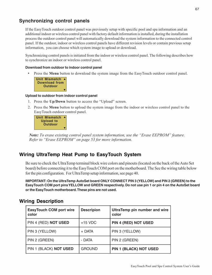
67
EasyTouch Pool and Spa Control System User’s Guide
Synchronizing control panels
If the EasyTouch outdoor control panel was previously setup with specific pool and spa information and anadditional indoor or wireless control panel with factory default information is installed, during the installationprocess the outdoor control panel will automatically download the system information to the connected controlpanel. If the outdoor, indoor or wireless control panels have different revision levels or contain previous setupinformation, you can choose which system image to upload or download.
Synchronizing control panels is initiated from the indoor or wireless control panel. The following describes howto synchronize an indoor or wireless control panel.
Download from outdoor to indoor control panel
• Press the Menu button to download the system image from the EasyTouch outdoor control panel.
Upload to outdoor from indoor control panel
1. Press the Up/Down button to access the “Upload” screen.
2. Press the Menu button to upload the system image from the indoor or wireless control panel to theEasyTouch outdoor control panel.
Note: To erase existing control panel system information, use the “Erase EEPROM” feature.Refer to “Erase EEPROM” on page 53 for more information.
Unit Mismatch Download from Outdoor
Unit Mismatch Upload to Outdoor
Wiring UltraTemp Heat Pump to EasyTouch System
Be sure to check the UltraTemp terminal block wire colors and pinouts (located on the back of the Auto Setboard) before connecting it to the EasyTouch COM port on the motherboard. The See the wiring table belowfor the pin configuration. For UltraTemp setup information, see page 40.
IMPORTANT: On the UltraTemp AutoSet board ONLY CONNECT PIN 3 (YELLOW) and PIN 2 (GREEN) to theEasyTouch COM port pins YELLOW and GREEN respectively. Do not use pin 1 or pin 4 on the AutoSet boardor the EasyTouch motherboard. These pins are not used.
Wiring Description
eriwtropMOChcuoTysaEroloc
noipircseD eriwdnarebmunnippmeTartlUroloc
)DER(4NIP DESUTON CDV51+ DESUTON)DER(4NIP
)WOLLEY(3NIP ATAD+ )WOLLEY(3NIP
)NEERG(2NIP ATAD- )NEERG(2NIP
)KCALB(1NIP DESUTON DNUORG DESUTON)KCALB(1NIP

68
EasyTouch Pool and Spa Control System User’s Guide
GlossaryControl Panel: The EasyTouch control panel with flexible hinge. Installed in upper portion of EasyTouch loadcenter to control the EasyTouch pool and spa system.
EMI (Electromagnetic interference) filter: Protective circuit element that must be used between theIntelliChlor transformer and supply lines.
High Voltage Panel/Compartment: Removable panel for the high voltage compartment of EasyTouch loadcenter. The high voltage wiring including circuit breakers, relays, GFCI and optional IntelliChlor transformer/filter.
Indoor Control Panel: This 9 or 13 button remote controller with LCD (liquid crystal display) is wired to thecontrol circuit board in the EasyTouch load center. The control panel can be wall mounted inside a house tocontrol the EasyTouch system.
IntelliChlor: Electronic salt chlorinator. Uses a process known as electrolysis to produce sodiumhypochlorite (liquid chlorine) from a low concentration of salt added to the pool water. Model IC 20 Cell (P/N520554) for pools up to 20,000 U.S. gallons (75 liters) and model IC 40 Cell (P/N 520555) for pools up to40,000 U.S. gallons (151 liters).
iS4: Four function spa-side remote. Spa wall or deck mounted.
Load Center: Metal enclosure with power relays, transformer, and circuit breakers. Used for distributingpower for controlling EasyTouch Systems. Also known as the “sub-panel.”
Low Voltage Compartment: Top compartment of EasyTouch load center for all low voltage wiring.
Low Voltage Raceway: Vertical space in the left side of EasyTouch load center for low voltage cabling.
Motherboard: The circuit board mounted behind the EasyTouch control panel.
Relay Circuits: The circuits that control the relays on the motherboard. Connectors on top edge of the circuitboard.
Screw Terminal Connector: Removable connector that may attach to circuit board with multiple sockets(anywhere from 2 to 6) to receive conductors from controllers and sensors; conductors held by screwterminals; multiple conductors of a small enough gauge (usually 22 AWG) may be coupled to a single socket ofa terminal connector.
Salt Chlorine Generator (SCG): Automated pool chlorinator that sanitizes using salt water (see IntelliChlor).
SpaCommand: Up to ten function spa-side remote with temperature changing capability. Can be spa wall ordeck mounted.
Transceiver: Used by the EasyTouch wireless control panel. Circuit board with attached antenna that cansend and receive radio frequency (wireless) transmissions.

Notes

Notes

Notes

P/N 521044 Rev A
*521044*