Easy-Touch™ Pro
46
Easy-Touch™ Pro User Manual
Transcript of Easy-Touch™ Pro

Easy-Touch™ ProUser Manual


Table of Contents
1. Introduction and Setup . . . . . . . . . . . . . . . . . . . . . . 1
1.1 High Voltage Warning . . . . . . . . . . . . . . . . . . . . . . 1
1.1.1 Prohibited Users . . . . . . . . . . . . . . . . . . . . . . . . . . . .1
1.1.2 High Voltage Safety . . . . . . . . . . . . . . . . . . . . . . . . .1
1.2 Customer Support . . . . . . . . . . . . . . . . . . . . . . . . 2
1.3 Optional Parts . . . . . . . . . . . . . . . . . . . . . . . . . . . . 3
1.4 Assembly . . . . . . . . . . . . . . . . . . . . . . . . . . . . . . . . 3
1.5 Installing Add-on Scanners . . . . . . . . . . . . . . . . . 3
1.5.1 Expanding to 1024 Test Points . . . . . . . . . . . . 9
1.6 Setting Up the Tester . . . . . . . . . . . . . . . . . . . . . 10
1.7 Using the Touch Screen . . . . . . . . . . . . . . . . . . . 12
1.7.1 Accessing Input Tools . . . . . . . . . . . . . . . . . . 12
1.8 Checking the System . . . . . . . . . . . . . . . . . . . . . 12
1.8.1 Checking the Sound . . . . . . . . . . . . . . . . . . . 12
1.9 Optional Software Features . . . . . . . . . . . . . . . 13
1.9.1 Enabling a Feature . . . . . . . . . . . . . . . . . . . . 14
1.10 Setting Up Security . . . . . . . . . . . . . . . . . . . . . . 15
1.10.1 Setting Up Easy-Wire Software Security . 15
1.11 Printing from the Easy-Touch Pro Tester . . . . . 17
1.11.1 Adding a Printer . . . . . . . . . . . . . . . . . . . . . . 17
2. Adapters . . . . . . . . . . . . . . . . . . . . . . . . . . . . . . . . . 19
2.1 Adapter Types . . . . . . . . . . . . . . . . . . . . . . . . . . . 19
2.2 Adapter Positions . . . . . . . . . . . . . . . . . . . . . . . 19
2.3 Adapter Sizes . . . . . . . . . . . . . . . . . . . . . . . . . . .20
2.4 Installing Adapters . . . . . . . . . . . . . . . . . . . . . . . 21
2.5 Removing Adapters . . . . . . . . . . . . . . . . . . . . . .22
2.6 Duplicating the Adapter Setup . . . . . . . . . . . .23
2.7 Adapter Signatures . . . . . . . . . . . . . . . . . . . . . .23
2.8 Cable Signatures . . . . . . . . . . . . . . . . . . . . . . . .23
3. Easy-Wire™ Software . . . . . . . . . . . . . . . . . . . . . . 25
3.1 Creating Default Adapters . . . . . . . . . . . . . . . . .25
3.2 Learning a Sample Cable . . . . . . . . . . . . . . . . .27
3.3 Verifying/Editing the Test Program . . . . . . . . .28
3.4 Testing the Device-Under-Test . . . . . . . . . . . .29
3.5 Easy-Wire Help . . . . . . . . . . . . . . . . . . . . . . . . . .30
3.6 Sharing Touch 1 & 1100 Programs . . . . . . . . . . 31
3.7 Importing Touch 1 or 1100 Programs . . . . . . . .35
3.8 Verifying Shared Programs . . . . . . . . . . . . . . . 37
3.9 Changing a Test Program Category . . . . . . . . 37
4. General Information . . . . . . . . . . . . . . . . . . . . . . . 38
4.1 Tester Maintenance . . . . . . . . . . . . . . . . . . . . . .38
4.2 Fixture Maintenance . . . . . . . . . . . . . . . . . . . . .38
4.3 Service . . . . . . . . . . . . . . . . . . . . . . . . . . . . . . . . .38
4.4 Calibration . . . . . . . . . . . . . . . . . . . . . . . . . . . . . .38
4.5 Tester Symbols . . . . . . . . . . . . . . . . . . . . . . . . . .38
4.6 Conditions for Operation . . . . . . . . . . . . . . . . .39
4.7 Warranty . . . . . . . . . . . . . . . . . . . . . . . . . . . . . . . .40
Table of Contents


Introduction and Setup 1
1. Introduction and SetupThis manual guides the user through the set up process and basic operation of the Cirris Easy-Touch™ Pro hardware and software. An overview is included on how to learn, verify, and test a sample cable. You can also learn how to share Touch 1/1100 test programs with Easy-Touch Pro test programs. To connect your tester(s) to a network, add a printer, or update your software, see the I.T. Administration Addendum. Talk to your Cirris account manager to obtain this document. The Easy-Touch Pro tester is controlled by the Easy-Wire software, which provides contextual help with more com-plete operating instructions. For information on how to access the Easy-Wire Help system, see page 30
1.1 High Voltage Warning
The Easy-Touch Pro tester provides the capability to perform high voltage Dielectric Withstand (DW) and Insulation Resistance (IR) testing. By design and purpose, the output of high voltage test equipment presents a risk of elec-tric shock. The extent of the risk is a function of the voltage, current and high voltage energy or charge. In order to mitigate the risk, the high voltage energy limit of the Easy-Touch Pro is 35 mJ and the high voltage charge limit is 45μC. These limits prevent circuits energized during high voltage testing from meeting the definition of hazardous or dangerous live points found in international standards.
● IEC 61010-1:2010, which specifies general safety requirements for electrical test and measurement equipment, states in section 6.3.1 that in a dry environment 60 volts DC or 30 Volts RMS (or greater) are deemed to be “HAZ-ARDOUS LIVE” if the current exceeds 0.5 mA RMS or 5 mA DC and the level of capacitive charge or energy exceeds 45μC at the same time. The maximum charge limit of 45μC means the high voltage output of the Easy-Touch Pro is not considered HAZARDOUS LIVE.
● European standard EN 50191 defines requirements for the erection and operation of electrical test equipment and focuses on measures to ensure operator safety. It states that compliance with the standard is not necessary if con-tact with live parts presents no danger, which it goes on to say is the case if the discharge energy does not exceed 350 mJ. The requirements of the standard are not mandatory for the Easy-Touch Pro due to the unit’s 35 mJ high voltage energy limit.
1.1.1 Prohibited Users
Individuals using a cardiac pacemaker, an insulin pump, or any other electronically-controlled medical device should NOT perform high voltage testing.
1.1.2 High Voltage Safety
The restricted high voltage energy and charge limits of the Easy-Touch Pro do not mean that performing hipot testing with the tester is entirely without risk as operators can still receive a startling or even painful shock. Therefore, it’s necessary and prudent to protect operators. Consider the following while recognizing it is not an exhaustive list.
2 Cirris® Easy-Touch™ Pro User Manual - 2021.2.0
TrainingOperators should only use the test equipment after they have been properly trained.
● Operators should understand the hazards of electricity and that electric current will take any path to ground including through a person.
● Operators should know how to use the test equipment and how to recognize when high voltage testing is being performed.
● Operators should understand not to touch the product being tested or any test fixture hardware during high volt-age testing
● Operators should understand test processes and their importance
● Operators should understand that untrained workers should not be allowed to use the test equipment.
Test StationTraining alone is not as effective as eliminating access to hazards.
● Protection from energized points can be accomplished by insulation, covers, enclosures, obstacles or safe dis-tance. A remote start button and/or safety interlock can be used as part of a protection strategy. The Easy-Touch Pro supports the use of either or both.
● Use a non-conductive surface for testing. Do not use an Electrostatic Discharge (ESD) station for testing. Conduc-tive materials can create a connection path between exposed connections or connector shells and the operator.
● Do no use the tester is a wet environment or in the presence of flammables gases or explosive fumes.
● Verify that the power outlet provides a properly wired, low impedance earth ground. The connection to earth ground is integral to the power cord supplied with the tester.
● Isolate high voltage testing from untrained employees and post high voltage warning signs at the test station boundary.
● See Ideas for Improving Hipot Safety on the Cirris web site for more information.
1.2 Customer SupportFor assistance with your Easy-Wire software, you may:
● Click the Help button at anytime to be taken to the Help System.
● Visit www.cirris.com/learning-center to read articles on Cirris software and other testing subjects.
● Contact our technical support team:
○ In the USA, call 1-800-441-9910 toll-free.
○ Outside the USA, visit our Cirris website at www.cirris.com to find the Cirris office nearest to you.

Introduction and Setup 3
1.3 Optional PartsYou can purchase Add-on scanners to expand the tester up to a total of 1024 test points in 128-point increments. You can also purchase adapters for connecting your device-under-test to the tester. You may have received the optional parts below:
● Add-on Scanner(s): Each Add-on scanner provides 128 test points. Connect up to seven scanners for a total of 1024 test points.
● Adapter(s)
○ A single-high adapter supports up to 28 test points and consumes 32 points.
○ A double-high adapter supports up to 64 test points and consumes 64 points.
○ A double-high adapter supports up to 120 test points and consumes 128 points.
1.4 AssemblyThe connector layout on your Easy-Touch Pro back panel may look different from the image below, but the connec-tors will be the same.
1. AC Input Connector: Connect IEC power cord (required).
2. Display Port: Connect a display cable (optional).
3. VGA Connector: Connect video cable (optional).
4. USB Ports: Connect USB thumb, drive mouse, printer, head set, etc. (optional).
5. Ethernet Connector: Connect networking cable (optional).
6. Audio Port: Connect headphones (optional).
7. Probe Port: Connect Probe (optional).
8. Digital I/O Port: Allows machines to send signals to and from the test system. For more information, visit www.cirris.com and search for digital I/O.
1
2 3 4 5
8
6
7
4 Cirris® Easy-Touch™ Pro User Manual - 2021.2.0
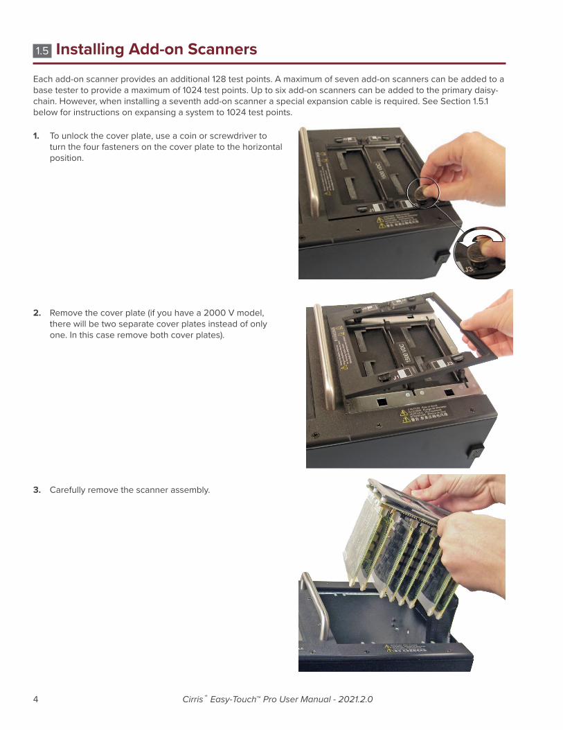
1.5 Installing Add-on ScannersEach add-on scanner provides an additional 128 test points. A maximum of seven add-on scanners can be added to a base tester to provide a maximum of 1024 test points. Up to six add-on scanners can be added to the primary daisy-chain. However, when installing a seventh add-on scanner a special expansion cable is required. See Section 1.5.1 below for instructions on expansing a system to 1024 test points.
1. To unlock the cover plate, use a coin or screwdriver to turn the four fasteners on the cover plate to the horizontal position.
2. Remove the cover plate (if you have a 2000 V model, there will be two separate cover plates instead of only one. In this case remove both cover plates).
3. Carefully remove the scanner assembly.

Introduction and Setup 5
Put it face-down next to the tester.
4. A plastic cover piece is attached to the right side of the tester by two rivets.
5. From the inside of the chassis, push both rivets out using a screwdriver or a hard, flat object.

6 Cirris® Easy-Touch™ Pro User Manual - 2021.2.0
6. Remove the cover piece.
7. Carefully put the scanner assembly back into the tester. Make sure the ribbon connector sticks out from the side of the tester.
8. Mate the add-on connectors. Make sure they are fully connected.

Introduction and Setup 7
9. Push the connectors into the main unit.
10. Push the two units together (fit the posts on the side of the add-on scanner into the holes on the side of the tester).
11. Attach the scanner add-on to the tester using the side latches on both sides of the tester.
If you’re attaching more than one scanner add-on, repeat the procedure attaching the next add-on onto the previous one.
Note: If your system is using all seven expansion scanners, see Section 1.5.1 below.

8 Cirris® Easy-Touch™ Pro User Manual - 2021.2.0
12. Re-attach the cover plate.
13. If you have multiple add-on scanners, consider writing the adapter positions on each add-on chassis with a per-manent marker. For example the first add-on scanner would be marked J5, J6, J7 and J8.
Note: If the position of the add-on scanners may be changed in the future, removable stickers may be a better alternative than permanent markings.

Introduction and Setup 9
15.1 Expanding to 1024 Test Points
If an Easy-Touch tester will be equipped with its maximum of seven expansion scanners (1024 test points total), a special internal cable, part number CBL-1024, is required. The cable is ONLY needed when expanding the tester beyond 896 points.
1. With power disconnected and the internal scanner removed from the chassis (steps 1-6 above), find the ribbon cable that connects the Analog board to the first scanner. The cable is marked 80-60016.wir EASY-TOUCH ANALOG TO SCANNER and it’s attached to a connector on the Analog board marked PRIMARY SCANNER SET close to the accessible edge of the board. The Analog board is mounted vertically on the front panel of the tester beneath the touchscreen.
2. On the Analog board, immediately adjacent to the PRIMARY SCANNER SET connector, and closer to the edge of the board, is an unused, 40-position, dual-row connector. Connect the end of the CBL-1024 cable that has a single, dual-row, 40-position connector to the previously unused connector on the Analog board (see graphic on next page).
3. Connect the first three Expansion Scanners to the Base Tester using the primary daisy-chain as described in steps 7 - 12 above. At the same time, route the CBL-1024 cable through the first three Expansion Scanner enclosures using the same chassis cutouts used for the primary daisy-chain.
4. Connect the CBL-1024 cable to the fourth Expansion Scanner (scanner #5) using the dual-row, 34-position connector at the end of the cable assembly.
40-pos, Dual-Row, Keyed,Female Connector (2 PLCS)
34-pos, Dual-Row, Keyed, Female ConnectorConnects to Scanner Motherboard (80-60016Easy-Touch Analog to Scanner Cable to Scanner#1, CBL-1024 to Scanner #5)
Easy-Touch 80-60016 Analog to Scanner Cable and CBL-1024 Cable (same design - di�erent lengths)
Connects to 80-22014Scanner Add-On Cable(Daisy-Chain Connector)
Connects to Analog Boardin Tester Base
80-22014 Scanner Add-On Cable
34-pos, Dual-Row, Keyed, Female ConnectorConnects to Scanner Motherboard
40-pos, Dual-Row, Keyed, Male ConnectorConnects to Daisy-Chain Connector on Standard Primary Daisy-Chain Cable, to CBL-1024 Cable or on another 80-22014 Scanner Add-On Cable
40-pos, Dual-Row, Keyed, Female ConnectorConnects to another 80-22014 Scanner Add-On Cable as needed (Daisy-Chain Connector)

10 Cirris® Easy-Touch™ Pro User Manual - 2021.2.0
5. Use scanner add-on cables, part number 80-22014, to connect scanners 6, 7 and 8 to scanner 5 in the standard daisy-chain configuration. The single dual-row, 40-position connector on one end of the 80-22014 Scanner Add-On Cable connects to the 40-position, in-line connector near the end of the CBL-1024 cable at Scanner 5.
1.6 Setting Up the Tester
1. Plug one end of the power cord into the tester. Plug the other end into a grounded outlet.
Base Tester128 Points
Scanner #1(Internal/Primary)
#2 #3 #4 #5 #6 #7 #8
Standard 80-60016 Analog to Scanner
Cable
Connector Marked “Primary Scanner Set”
Analog Board Mounted Vertically Inside Chassis on
Front PanelScanner Add-On Cable,
80-22014 (6 Places)
Easy-Touch cable layout with detail removed for clarity(Cables routed internally through enclosures)
Cross-section View (Analog Board pictured horizontally for clarity)
Special Cable, CBL-1024
Scanner Add-On Cables, 80-22014In testers with up to 896 points (6 Expansion Scanners / 7 Scanners total) this primary daisy-chain continues through the last scanner
Scanner Add-On Cable, 80-22014
Special Cable, CBL-1024(only req’d in testers with 1024 points)

Introduction and Setup 11
2. Insert the probe if desired.
3. Push in the power button until the tester powers on.
4. When the Easy-Wire “User Login” window opens. Press ‘OK.’
Note: Initially, no password is required for the “Master Login” user. To learn how to create user logins and passwords, see “Setting Up Software Security” on page 15.

12 Cirris® Easy-Touch™ Pro User Manual - 2021.2.0
1.7 Using the Touch ScreenTo navigate the Easy-Wire software on your Easy-Touch Pro, you can touch the screen or use a USB keyboard and mouse plugged into the tester. Within this manual, the commands “touch” or “press” are equivalent to the command “click” if you are using a mouse.
The equivalent commands for a mouse and a touch screen are displayed below.
● Mouse: Touch Screen
● Left-click: Touch the screen once
● Double-click: Quickly touch the screen twice
● Right-click: Touch and hold your finger on the screen
The Easy-Wire software sometimes requires the user to enter data. Data can be entered by using an attached USB external keyboard, using a barcode scanner or by using the on-screen keyboard.
● When Touching a text box, the on-screen keyboard automatically appears
● To close the keyboard, press the X button in the upper right corner of the keyboard
1.7.1 Accessing Input ToolsCirris Easy-Wire software sometimes requires the user to enter data. Data can be entered by attaching an external keyboard or a barcode scanner. You can also use the PM1 write-in tool or on screen keyboard.
1. When you touch a text box in Easy-Wire, a keyboard appears.
2. To close the keyboard, press the X button in the upper right corner.
1.8 Checking the SystemWhen the tester boots up it goes through a series of self-tests. In the Easy-Wire main menu, you can tell if the tests pass or fail by checking the status indicator.
1. In the Easy-Wire main menu, verify that the status indicator displays Ready.
2. If the status indicator displays Ready the tester is working and ready for use.
3. If the status indicator displays Error the tester failed one or more of the self tests. Try rebooting the tester. If the problem persists write down the error messages that appear after launching the software and call a Cirris representative for assistance.
1.8.1 Checking the SoundIn the Easy-Wire main menu press the sound button. You should hear two trumpet sounds coming from your tester. If you do not hear the sound or want to change the volume, continue with the steps below.

Introduction and Setup 13
1. In the Easy-Wire main menu, press Utilities.
2. Press Setup System Options
.
3. Open the Computer tab and press Change Volume.
4. Sound Control will open displaying two volume controls.
● System Volume: controls the overall sound in Easy-Wire including the Good cable and Bad able sounds in the test window.
● Test Sound Volume: Controls the volume of the good cable ticking sounds that occur during a continuous test.
5. Press OK.
6. Press Done to return to the main menu.
1.9 Optional Software FeaturesThe “Alternate Language” feature allows you to change the software language. To register this feature, see “Optional Software Features” in the Easy-Wire help system. The following optional features are also available for the Easy-Touch Pro tester:
● Measured Values: The Easy-Wire reporting capability allows you to capture and store the measured values of all tests. You can store data for low voltage (LV) and high voltage (HV) values along with the actual measured values of all components. This is called “Data Collection” when enabled.
● AC High Voltage: This option allows you to perform AC hipot tests up to 1000 VAC (RMS). Note: With 1000 VDC testers the AC option is limited to 700 VAC (RMS).
● Scripting: This option allows you to adapt the tester’s behavior to fit your needs, add new features, and ease automation of tasks in the tester. Most scripting developed for 1100H+ and Touch-1 testers will work on the Easy-Touch Pro tester. Scripting examples can be found under the documentation tab on the Easy-Touch Pro product page at cirris.com.

14 Cirris® Easy-Touch™ Pro User Manual - 2021.2.0
1.9.1 Enabling a FeatureEnabling an optional feature is a one-time operation. Each new feature requires a feature key provided by Cirris. The feature key is based on the serial number of the tester and the feature being enabled.
1. In the Easy-Wire main menu, press ‘Utilities.’
2. Press ‘Setup System Options.’
3. In the “Tester Hardware” tab, press ‘Enable Features.’
4. The “Features Available on this Tester” window will display both “Features Installed” and “High Voltage Limits” on the left side of the screen. Follow instructions 1-3 on the right side of the screen to enable the feature (as shown).

Introduction and Setup 15
5. After you press ‘Install the Feature,’ the feature will display under “Features Installed” on the left side of the window. After you install a feature, you must activate the feature in your test program(s). For more information, press ‘Help.’ Otherwise, press ‘Done.’
6. Press ‘OK.’
7. Press ‘Done’ to return to the main menu.
1.10 Setting Up SecurityYou can set up two different types of security in the Easy-Touch Pro tester:
● Windows System Security: This restricts access to the Windows 7 administrative account in your Easy-Touch Pro tester. If security is important to your environment, you can change the password that allows access into this account. For more information, see the “I.T. Administration Addendum.”
● Easy-Wire Software Security: This allows you to restrict operator access to the Easy-Wire software via user log-in and password control. If each operator on your production floor has a unique user login and password, you can track collected test data down to the individual operator. User logins that do not have passwords can be accessed by any of your Easy-Touch Pro operators. The Easy-Wire software ships with four pre-defined users: Master Login, Test Engineer, Line Supervisor, and Line Worker. Each user has pre-defined security restrictions. You can create passwords for the existing users and create new user logins and passwords. You can change the security settings for a pre-defined user; however, the “Master Login” user’s security settings cannot be changed. For lost passwords, call Cirris for assistance.
1.10.1 Setting Up Easy-Wire Software Security1. From the Easy-Wire main menu, press ‘Utilities.’

16 Cirris® Easy-Touch™ Pro User Manual - 2021.2.0
2. Press ‘Setup Security.’
3. If you want to change the password for an existing user, select the desired user, press ‘Change Password,’ and skip to step 6.
If you want to create a new user, select an existing profile from the “Available Users” list, and press ‘Create New User from selected user’ as shown (the name will appear as the profile name followed by the word “copy”).
4. Rename the user in the “Selected User” text box, then press anywhere in the white space of the “Security Set-tings” box to save the name.
Note: To delete a user, right-click on the user login and click ‘Delete.
’
5. Select the user name, and press ‘Change Password for selected user.’ If you are creating a password for the Master Login, you would highlight “Master Login.”

Introduction and Setup 17
6. Enter the same password into each text box and press ‘OK.’
7. If desired, you can now customize the security settings of the user in the “Security Settings” section. Check the boxes to turn the settings on or off, and then press ‘Done.’
8. Press ‘Yes’ to save the changes.
9. Press ‘Done’ to return to the main menu.
1.11 Printing from the Easy-Touch Pro TesterYou can print from stand-alone Easy-Touch Pro testers or from a network. For stand-alone testers, printers should be added in the Windows shell of the “Cirris” administrative user. See “Adding a Printer” below. If you have more than one printer, you may need to select the desired printer each time you print. If the printer you most commonly print to does not display first in the list of printers on the print screen, you should change the default printer. See “Selecting a Default Printer for the ‘Easy-Touch Pro’ User” in the “I.T. Administration Addendum” on page 7. For further information on network printing, see the “I.T. Administration Addendum” on page 8.
1.11.1 Adding a Printer1. Log into the “Cirris” administrative user account:
2. Attach a USB keyboard to the Easy-Touch Pro tester.
3. Press the power button for about two seconds to power on the tester.
4. The “User Login” window will display. Press Ctrl+Alt+Delete on the keyboard and choose the “Log Off” option.
5. The Windows login screen will open showing the “Cirris” user icon and the “Easy-Touch Pro” user icon. Select the “Cirris” user. The default “Cirris” user password is: signature1 (all lowercase, no spaces).

18 Cirris® Easy-Touch™ Pro User Manual - 2021.2.0
6. Install drivers then, when prompted, plug the printer into the Easy-Touch Pro.
Note: If your printer drivers are on a CD, you will have to either transfer them to a thumb drive or connect to a network to load the drivers.

Adapters 19
2. AdaptersInterchangeable adapter cards connect your cables to the Easy-Touch Pro tester. Cirris adapters are designed to mate with many industry-standard connectors.
2.1 Adapter TypesEach Cirris adapter has a part number. Use this part number when referring to the adapter for ordering or trouble-shooting. The Cirris adapter types are listed below:
● Standard Adapters: Standard adapters can be used for testing up to 1000 VDC and 700 VAC. These adapters are identified by a part number starting with the uppercase letter “A.” Standard adapters are labeled by the connector they mate to on the device-under-test (e.g. AHED-26 mates to: 26 POS. 1” FEM).
● High Voltage Adapters: These adapters can be used for testing up to 1500 VDC and 1000 VAC. High Voltage adapter part numbers begin with the uppercase letter “H” (e.g. HHED-26). For more information on which stan-dard adapters are available in high voltage, visit www.cirris.com or call 1-800-441-9910.
● Custom Adapters: These are limited-production adapters designed for unique connectors. These adapters are identified by a part number starting with a combination of two uppercase letters “A” followed by 5 numbers in the following format: AA<xx>-<nnn>, where <xx> is the number of pins (e.g. AA10-345, AB10-345, AC10-123).
● Replaceable Adapters: These adapters allow you to replace worn adapter connectors with new ones. Replace-able adapter part numbers begin with an uppercase letter “R” (e.g. RHED-26).
2.2 Adapter PositionsThe Easy-Touch Pro tester has four adapter positions: J1, J2, J3, and J4. Each add-on scanner provides four more adapter posi-tions up to a maximum of 32 positions. Note the J1, J2, J3, and J4 labels on the Easy-Touch Pro cover plate in the image below.

20 Cirris® Easy-Touch™ Pro User Manual - 2021.2.0
2.3 Adapter SizesCirris adapters come in three sizes: Single-high, Double-high, and Quad-high.
● Single-high Adapters: These adapters support up to 28 test points and consume 32 test points. Single-high adapters can occupy any of the four “J” positions. The image below shows a Single-high adapter in position J1 (positions J2, J3, and J4 are still available).
● Double-high Adapters: These adapters support up to 64 test points and consume 64 test points. Double-high adapters can occupy the J1 and J3 positions. The image below shows a Double-high adapter in position J1 (posi-tions J3 and J4 are still available).
● Quad-high Adapters: These adapters support up to 120 test points and consume 128 test points. Quad-high adapters can only occupy position J1. The image below shows a Quad-high adapter in position J1 (no other posi-tions are available).

Adapters 21
2.4 Installing AdaptersEasy-Touch Pro models sold after March 2012 (1500 V model) are equipped with a slide-lock scanner that allows you to lock and unlock test adapters (without the need to remove the J3-J4 cover plate, install the adapter, then reattach the cover plate, as was the case with traditional Cirris testers). Note: The 2000 V model has the traditional cover plates.
1. Make sure the slides are pushed completely outward. If you have a 2000 V model, remove the cover plate.
2. Fully insert adapters by pushing the adapter against the edge of the scanner until the adapter fully seats. Be careful not to bend the pins.
Note: You must install adapters in the J1-J2 positions before installing them in the J3-J4 positions.
22 Cirris® Easy-Touch™ Pro User Manual - 2021.2.0
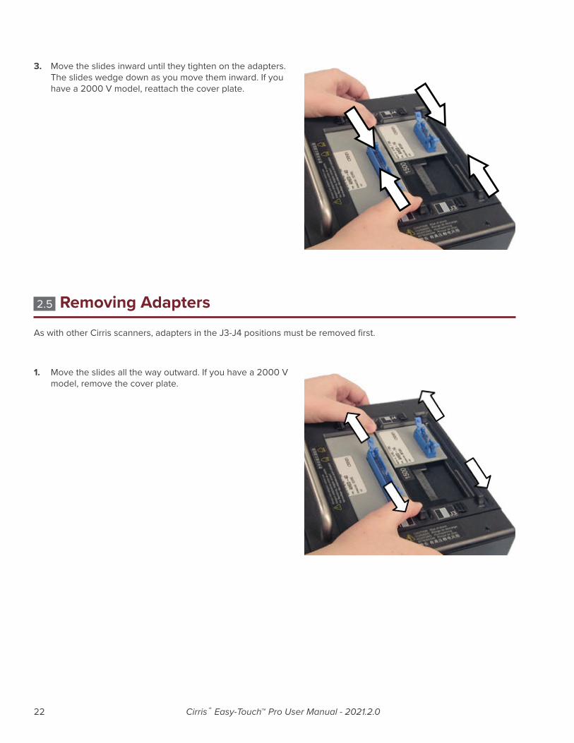
3. Move the slides inward until they tighten on the adapters. The slides wedge down as you move them inward. If you have a 2000 V model, reattach the cover plate.
2.5 Removing AdaptersAs with other Cirris scanners, adapters in the J3-J4 positions must be removed first.
1. Move the slides all the way outward. If you have a 2000 V model, remove the cover plate.

Adapters 23
2. Remove the adapters.
2.6 Duplicating the Adapter SetupWhen you run a test program in Easy-Wire, the adapters must be placed in the same positions that were defined when the test program was created. If you don’t know the original adapter positions of a test program, you can find out the adapter positions using one of the following methods:
● In the Easy-Wire main menu, select the desired test program and press ‘Edit/View.’ The part numbers and adapter positions will be listed in the “Define Adapters” tab (tab 1).
● In the Easy-Wire main menu, select the desired test program and press ‘Test.’ The test window will indicate a missing adapter and display the part number and position of the missing adapter(s).
● Reference your written documentation.
2.7 Adapter SignaturesEach adapter has a numerical identifier called the Adapter Signature, which verifies the test setup. Adapter signatures identify how many pins are in the adapter, where pin 1 is located, and how the pins are numbered. Adapter signatures are printed on the adapter labels. For more information about Cirris adapters, see www.cirris.com/adapters.
2.8 Cable SignaturesWhen a cable is learned, the tester derives an 11-digit alphanumeric code called a Cable Signature (for example: 1B4137-4Z020). The cable signature helps you easily identify a proper test setup.
Cable signatures have two parts:
● The Connection Signature is the first part of a cable signature, which identi-fies a particular cable. The tester derives the Connection Signature from the following factors:
○ The wire pattern of the tested cable
○ The adapters used
○ The adapter positions

24 Cirris® Easy-Touch™ Pro User Manual - 2021.2.0
● The Parameter Signature is the last part of a cable signature, which identifies Test Parameter settings for the test.
■ ExampleThe Cable Signatures for these two cables indicate identical connections, but different Test Parameter Settings.
3F09EF-2J8NH 3F09EF-52AE3
The Cable Signatures for these two cables indicate the same Test Parameter Settings, but different connections and connectors.
3F09EF-2J8NH 54GF03-2J8NH
Note: If a test program has components, the parameter signature is -MULTI. If a test program has advanced hipot settings, the parameter signature is -00000.

Easy-Wire™ Software 25
3. Easy-Wire™ Software
3.1 Creating Default AdaptersSome commonly used adapters in Easy-Wire are set as “Default.” If your adapters have this setting, you can learn a sample cable or import test programs without being prompted to select each adapter in your test program. You can create and edit your own adapters and set them as default; however, the adapters that come with Easy-Wire are not editable.
1. In the Easy-Wire main menu, press ‘Connector Type Library.’
2. Press the “User Signature Adapters” tab.
3. Install the adapter you want to add as a default adapter.
4. Press ‘Create.’

26 Cirris® Easy-Touch™ Pro User Manual - 2021.2.0
5. The tester calculates the installed adapter signature num-ber(s). Select the first adapter in the list, and press ‘OK.’
6. In the designated “Part Number” box, enter the part number of the first adapter. The “Mates to” comment box is optional. Then check the “Shared Signature Default” box to set the adapter to “Default.” When you are finished, click ‘OK.’
7. You can come back later and draw a graphical representation of your adapter if desired. To move quickly to the next step press ‘No.’ For more information on graphical representations, see the Easy-Wire help system.
8. Select an adapter category and click ‘OK.’
9. If you have more than one attached adapter, click ‘Create’ again and repeat this process substituting the new adapter signature and adapter part number in steps 5 and 6.
10. When you are finished creating adapters, the “Connector Type Library” will be open. Click ‘Close’ to return to the main menu.
Easy-Wire™ Software 27
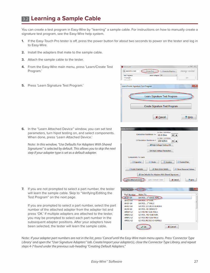
3.2 Learning a Sample CableYou can create a test program in Easy-Wire by “learning” a sample cable. For instructions on how to manually create a signature test program, see the Easy-Wire help system.
1. If the Easy-Touch Pro tester is off, press the power button for about two seconds to power on the tester and log in to Easy-Wire.
2. Install the adapters that mate to the sample cable.
3. Attach the sample cable to the tester.
4. From the Easy-Wire main menu, press ‘Learn/Create Test Program.’
5. Press ‘Learn Signature Test Program.’
6. In the “Learn Attached Device” window, you can set test parameters, turn hipot testing on, and select components. When done, press ‘Learn Attached Device.’
Note: In this window, “Use Defaults For Adapters With Shared Signatures” is selected by default. This allows you to skip the next step if your adapter type is set as a default adapter.
7. If you are not prompted to select a part number, the tester will learn the sample cable. Skip to “Verifying/Editing the Test Program” on the next page. If you are prompted to select a part number, select the part number of the attached adapter from the adapter list and press ‘OK.’ If multiple adapters are attached to the tester, you may be prompted to select each part number in the subsequent adapter positions. After your adapters have been selected, the tester will learn the sample cable.
Note: If your adapter part numbers are not in the list, press ‘Cancel’until the Easy-Wire main menu opens. Press ‘Connector Type Library’ and open the “User Signature Adapters” tab. Create/import your adapter(s), close the Connector Type Library, and repeat steps 4-7 found under the previous sub-heading “Creating Default Adapters.”
28 Cirris® Easy-Touch™ Pro User Manual - 2021.2.0
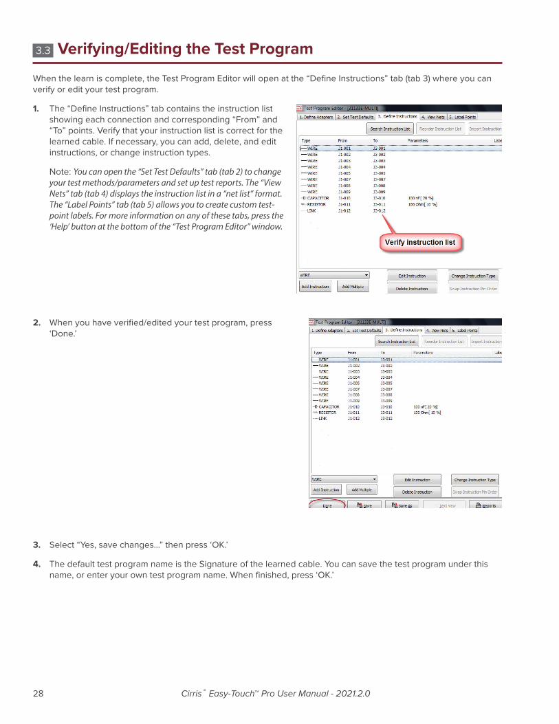
3.3 Verifying/Editing the Test ProgramWhen the learn is complete, the Test Program Editor will open at the “Define Instructions” tab (tab 3) where you can verify or edit your test program.
1. The “Define Instructions” tab contains the instruction list showing each connection and corresponding “From” and “To” points. Verify that your instruction list is correct for the learned cable. If necessary, you can add, delete, and edit instructions, or change instruction types.
Note: You can open the “Set Test Defaults” tab (tab 2) to change your test methods/parameters and set up test reports. The “View Nets” tab (tab 4) displays the instruction list in a “net list” format. The “Label Points” tab (tab 5) allows you to create custom test-point labels. For more information on any of these tabs, press the ‘Help’ button at the bottom of the “Test Program Editor” window.
2. When you have verified/edited your test program, press ‘Done.’
3. Select “Yes, save changes...” then press ‘OK.’
4. The default test program name is the Signature of the learned cable. You can save the test program under this name, or enter your own test program name. When finished, press ‘OK.’
Easy-Wire™ Software 29
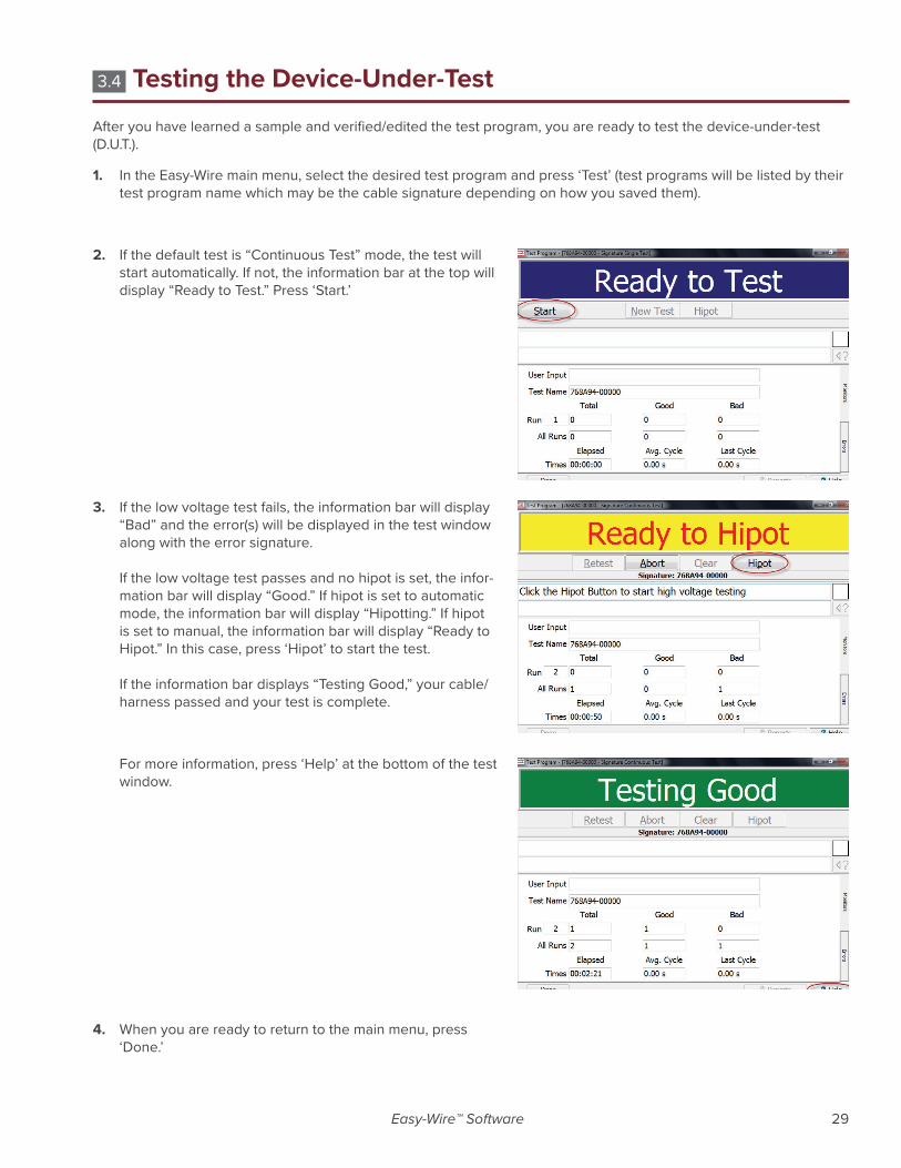
3.4 Testing the Device-Under-TestAfter you have learned a sample and verified/edited the test program, you are ready to test the device-under-test (D.U.T.).
1. In the Easy-Wire main menu, select the desired test program and press ‘Test’ (test programs will be listed by their test program name which may be the cable signature depending on how you saved them).
2. If the default test is “Continuous Test” mode, the test will start automatically. If not, the information bar at the top will display “Ready to Test.” Press ‘Start.’
3. If the low voltage test fails, the information bar will display “Bad” and the error(s) will be displayed in the test window along with the error signature. If the low voltage test passes and no hipot is set, the infor-mation bar will display “Good.” If hipot is set to automatic mode, the information bar will display “Hipotting.” If hipot is set to manual, the information bar will display “Ready to Hipot.” In this case, press ‘Hipot’ to start the test. If the information bar displays “Testing Good,” your cable/harness passed and your test is complete.
For more information, press ‘Help’ at the bottom of the test window.
4. When you are ready to return to the main menu, press ‘Done.’

30 Cirris® Easy-Touch™ Pro User Manual - 2021.2.0
3.5 Easy-Wire HelpThe complete Easy-Wire manual is available when you press the Help button in any window in Easy-Wire. Sections of the manual may be printed if desired.
1. Press ‘Help’ in any window in Easy-Wire. The help informa-tion for that window will open.
2. If there is an information bar at the top of the screen, right-click the information bar and then press ‘Allow Blocked Content.’ If there is no information bar, skip to step 4.
3. When the security warning opens, press ‘Yes.
’
4. To view the entire Easy-Wire manual by chapter, press ‘Contents.’

Easy-Wire™ Software 31
5. Press any link to view the help for that topic.
Note: In every Help page, you can do the following:
● Press ‘Contents’ to view the Easy-Wire manual by chap-ter.
● Press ‘Search’ to find information using keywords.
● Press ‘Contact’ to view Cirris contact information for.
● Press ‘Website’ to view the Cirris website if you are con-nected to the Internet.
3.6 Sharing Touch 1 & 1100 ProgramsYou can copy your existing Touch 1 (T1) or Signature 1100 test programs into the Easy-Touch Pro tester. Once copied, you can assign these files to a specified category and they will automatically be synchronized if your testers are net-worked. If not, you can manually synchronize these shared programs using a USB thumb drive (sneaker net).
T1 and 1100 test programs exist as flat files with a .wir extension. Easy-Wire test programs reside inside the Easy-Wire database and are not accessible externally. In order to share the two, Cirris has made it possible to make a “bridge.” To form this bridge, you must first create a special Easy-Wire category that points to the directory path where the T1/1100 .wir files are located. Next, you must import the T1/1100 test programs into the Easy-Wire database and assign them to the category. Then, you can edit a test program in either location and the software will automatically update the corresponding test program in the other location.
Cirris recommends that you create new test programs for this category in the Easy-Wire database so they will be automatically created as .wir files for your T1 or 1100. If you create them on your T1 or 1100, you will have to manually import them into the Easy-Wire database.
Note: If you have multiple Easy-Touch Pro testers, you can put them on a computer network. However, Cirris recommends that you purchase the optional Cirris Server Networking Software so that all Easy-Wire data exists in one Easy-Wire network server database. For more information, see the networking section in the Easy-Touch Pro I.T. Administration Addendum.

32 Cirris® Easy-Touch™ Pro User Manual - 2021.2.0
1. Put your Touch 1 or 1100 wirelists in a file location you can access from your Easy-Touch Pro tester, either on a thumb drive locally or on a network.
2. In the Easy-Wire main menu, press ‘Utilities.
3. Press ‘Category Maintenance.’
4. In the first text drop-down box, select ‘<New Category>.’
Note: The pre-defined categories “Demo,” Military,” and “Stan-dard” cannot see a file location outside of Easy-Wire. You must create a new category.

Easy-Wire™ Software 33
5. In the second text box, enter a name for the new category. You may want to name the category for specific customers.
6. Ensure that the “Test Program” box is selected.
7. Press the “Master File Directory” browse button.
8. Browse to the file location that contains your Touch 1 or 1100 wirelists. In this example, the Touch 1 files are in drive D in a folder called “Touch 1.” Select the folder and press ‘OK.’

34 Cirris® Easy-Touch™ Pro User Manual - 2021.2.0
9. Notice that the file location displays as the directory. Press ‘Add.’
10. Press ‘Done.’
11. Press ‘Done’ to return to the main menu. You are now ready to import the Touch 1 or 1100 wirelists into the Easy-Touch Pro database.
Important! During the importing process, you will have the option to select a category for imported test program(s). Ensure that you select the category you created in step 4. This will allow wirelists to be synchronized in both the Easy-Touch Pro database and your Touch 1 or 1100 file location.
12. See “Importing Touch 1 or 1100 Wirelists” on the next page.
Easy-Wire™ Software 35
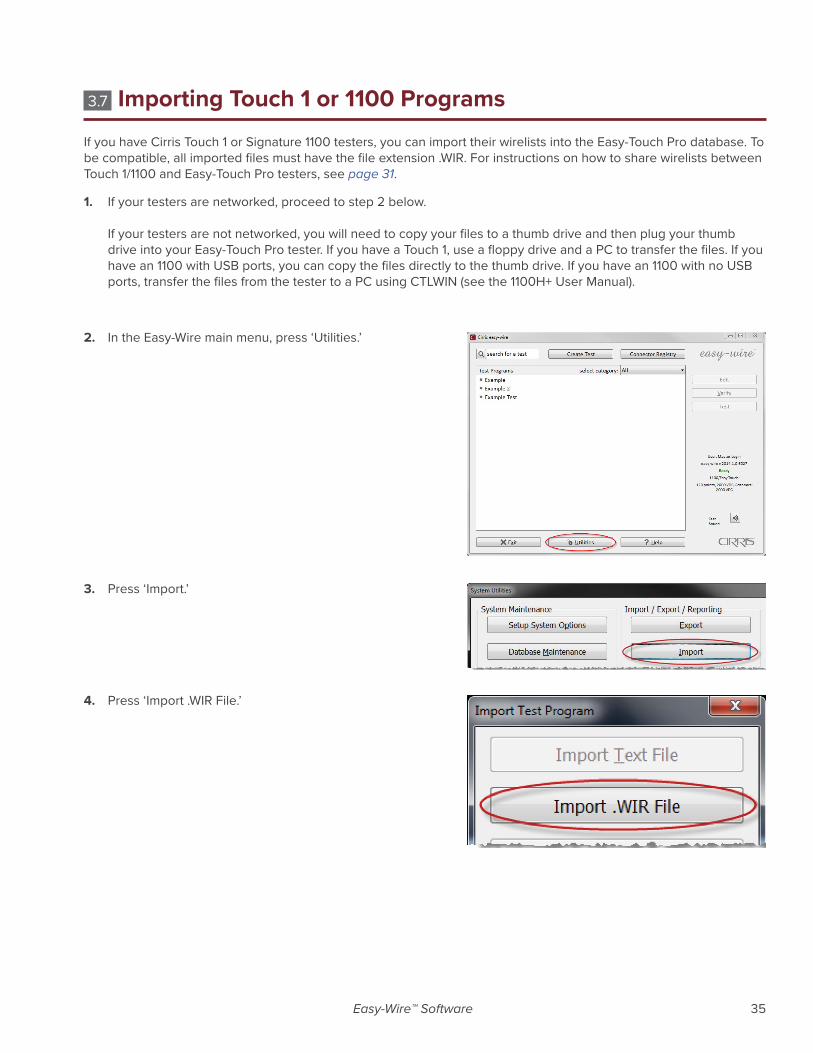
3.7 Importing Touch 1 or 1100 ProgramsIf you have Cirris Touch 1 or Signature 1100 testers, you can import their wirelists into the Easy-Touch Pro database. To be compatible, all imported files must have the file extension .WIR. For instructions on how to share wirelists between Touch 1/1100 and Easy-Touch Pro testers, see page 31.
1. If your testers are networked, proceed to step 2 below. If your testers are not networked, you will need to copy your files to a thumb drive and then plug your thumb drive into your Easy-Touch Pro tester. If you have a Touch 1, use a floppy drive and a PC to transfer the files. If you have an 1100 with USB ports, you can copy the files directly to the thumb drive. If you have an 1100 with no USB ports, transfer the files from the tester to a PC using CTLWIN (see the 1100H+ User Manual).
2. In the Easy-Wire main menu, press ‘Utilities.’
3. Press ‘Import.’
4. Press ‘Import .WIR File.’

36 Cirris® Easy-Touch™ Pro User Manual - 2021.2.0
5. Browse to the location on your thumb drive or network drive of your Touch 1 or 1100 files. Select the file and press ‘Open.’
6. If prompted, select the part number for the first adapter position in the test and press ‘OK.’
Note: If you have multiple adapters, you will be prompted to repeat this step for each adapter in the test.
7. If you have more wirelists to import, press ‘Import .WIR Files’ and repeat steps 1-6, or multi-select the wirelists.
8. When you have imported all of your wirelists, press ‘Done.’
9. Press ‘Done’ to return to the main menu.
10. In the Easy-Wire main menu, select the category you saved the wirelists into or select the “All” category to verify that the test programs you imported are in the Test Program List.

Easy-Wire™ Software 37
3.8 Verifying Shared ProgramsIf you created a new category for sharing Easy-Touch Pro test programs and Touch 1 or 1100 wirelists, you can verify that the procedure worked by checking the files in both locations to see if they are the same and by doing the follow-ing:
1. In the Easy-Wire main menu, select the category you creat-ed or select the “All” category.
2. A yellow box next to the test program name indicates a shared test program between the Easy-Wire database and the Touch 1 or 1100 file location.
Note: In the Easy-Wire main menu, you can assign existing test programs to the category for shared wirelists if you want to use them on your Touch 1 or 1100 tester. See “Moving Test Programs Between Categories” in the next section.
3.9 Changing a Test Programs CategoryIn the Easy-Wire main menu, you can move any test program to an alternate category. If you have shared test pro-grams between your Touch 1/1100 and Easy-Touch Pro testers, you can move test programs into the shared category to copy them into the T1/1100 file location. Similarly you can stop sharing test programs by assigning them to another category.
1. Press and hold (right-click) on the test program you want to move to another category. From the right-click menu, press ‘Category.’ Select the desired category.

38 Cirris® Easy-Touch™ Pro User Manual - 2021.2.0
4. General Information
4.1 Tester MaintenanceThe Easy-Touch Pro tester requires no maintenance. If desired you may clean the outside surfaces of the tester. Since some cleaning agents leave a conductive residue, take special care to not allow the cleaning agents to come in con-tact with the test point connectors or the circuitry inside the casework.
4.2 Fixture MaintenanceThe fixturing contacts that mate to the device-under-test may wear due to repeated insertion cycles. Contact wear can result in higher connection resistances which increases the measured resistances for the device-under-test. For this reason Cirris recommends that customers evaluate the number of mating cycles and the cycle life of fixture con-tacts to determine maintenance intervals for testing and/or replacing fixturing contacts. A good way to check fixture contact resistance is to construct and use a shorting block. For more information on creating shorting blocks, see http://www.cirris.com/adapters/test-adapt.html.
4.3 ServiceCirris Testers are modular in design for easy servicing. If your Cirris tester requires service, as determined by Cirris support personnel, you may need to send the affected module or the entire tester back to Cirris for repair. A loaner tester can be sent to you. You should not attempt to service any circuit board at the component level. All compo-nent-level service should be performed by Cirris technicians.
4.4 CalibrationA Certificate of Calibration was provided with the tester. Before leaving the factory, every Easy-Touch Pro tester is calibrated in compliance with ANSI/NCSL Z540-1-1994 and MIL-STD-45662A using standards traceable to the NIST in the United States. The calibration of the tester should thereafter be verified annually. To verify calibration and func-tionality, you can purchase the Easy-Touch Pro Performance Check Kit. In addition to the performance check kit, you need a calibrated volt meter and high voltage probe capable of measuring up to 1500 VDC.
Note: In the event a Cirris tester is found to be out of calibration, there are no adjustable controls. The tester, or affected portions of the tester, must be sent back to a Cirris facility for repair.
4.5 Tester Symbols
Caution: See manual for more information Risk of shock

General Information 39
The yellow lightning bolt symbols on the tester inform operators that high voltage is involved with the scanner mod-ules and that there is risk of electric shock. The yellow exclamation mark means to use caution and also to see the manual for more information.
When performing a high voltage test, the Easy-Touch Pro tester limits the Total Current to 2.5 milliamps and the applied charge to 45 micro coulombs. These electrical levels are considered safe for adults; however, some people could be adversely affected even at these levels. To avoid risk, ensure that you do not touch the cable during the hipot test. Using a DC voltage for high voltage testing also provides an added level of operator safety. See the Cirris website for more hipot safety information.
See manual for more information
The symbols with a white exclamation mark on the back of the tester, inform operators that more information about the Digital I/O, Auxiliary HV input, and Auxiliary Input Supply Connections can be found in the Easy-Wire on-line help system.
The Digital I/O Connector allows the tester to respond to inputs and create outputs without the use of a PLC. Easy-Wire software version 2012.2 or higher has Digital I/O capability. See the Easy-Wire help system for more information.
4.6 Conditions for OperationYour Easy-Touch Pro Tester is intended to be used indoors at a temperature of 50 to 104 degrees Fahrenheit (10 to 40 degrees Celsius).
Best performance can be obtained at a relative humidity of less than 70%. Insulation Resistance Measurements will degrade at over 70% relative humidity.
The unit can be mounted in a ventilated compartment. Be sure not to block the vents on the sides and back of the tester.
Never apply live voltages to the test points or probe input of your Cirris tester. Power supplies and other accessories not approved by Cirris may cause damage or present a hazard. If you use a Cirris product in a manner not specified in this manual and the accompanying help system, the protection provided by the product may be impaired.

40 Cirris® Easy-Touch™ Pro User Manual - 2021.2.0
4.7 WarrantyCirris, Inc. warrants the Easy-Touch Pro analyzer to be free of defects in materials and workmanship for a period of one (1) year from the date of delivery to you, as evidenced by receipt of your warranty registration form. In the event a defect develops due to normal use during the warranty period, Cirris will repair or replace the analyzer with a new or reconditioned unit of equal value.
In the event of replacement with a new or reconditioned model, the replacement unit will continue the warranty peri-od of the original analyzer. Replacement units will be returned by the same method shipped; generally within one (1) working day.
If analyzer failure results from accident, abuse, or misapplication, Cirris, Inc. shall have no responsibility to replace the analyzer or refund the purchase price. Defects arising from such causes will be considered a breach of this warranty. Cirris, Inc. is not responsible for special, incidental, or consequential damages resulting from any breach of warranty, or under any other legal theory, including lost profits, downtime, goodwill, damage to or replacement of equipment and property, and any costs of recovering materials used with the Easy-Touch Pro Analyzer.
ANY IMPLIED WARRANTIES ARISING OUT OF SALES OF THE Easy-Touch ANALYZER, INCLUDING BUT NOT LIMITED TO IMPLIED WARRANTIES OF MERCHANTABILITY AND FITNESS FOR A PARTICULAR PURPOSE ARE LIMITED IN DURATION TO THE ABOVE STATED ONE (1) YEAR PERIOD. CIRRIS, INC. SHALL NOT BE LIABLE FOR INCIDENTAL OR CONSEQUENTIAL DAMAGE, EXPENSES, OR ECONOMIC LOSS.
Some states do not allow limitations on length, or implied warranty, or the exclusion or limitation of incidental or con-sequential damages, so the above limitations or exclusions may not apply to you.
This warranty gives you specific legal rights and you may also have other rights, which vary from state to state.
Cirris, Inc.
Salt Lake City, Utah.
PLEASE RECORD PURCHASE DATE AND SERIAL NUMBER BELOW.
DATE: ________________________________
SERIAL NUMBER: ______________________

41

Easy-Touch™ Pro User ManualVersion 2021.2.0
© 2021 Cirris, Inc.401 North 5600 West
Salt Lake City, UT 84116USA
www.cirris.com