Eagle-Z-Bike Service Manual - Home | Scooter Doc … service manual contains information on...
75
1 Eagle and Z-Bike Service Manual February 2007
Transcript of Eagle-Z-Bike Service Manual - Home | Scooter Doc … service manual contains information on...

1
Eagle and Z-Bike
Service Manual
February 2007

2
Foreword This service manual contains information on servicing the Eagle and Z-Bike. This manual is written for use as a guideline only. It is recommended that any technician, with or without sufficient experience, thoroughly read through the manual and only attempt to service those areas that are fully understood in accordance with the guidelines provided by this manual. For fully qualified technicians, this manual supplies service data necessary for repairs and maintenance. It is highly recommended that a qualified technician, regardless of technical level, should study the service manual in full before attempting service on the Eagle and Z-Bike. Safety is our primary concern; please always use the proper safety precautions when working with any machinery. Safety glasses should be worn at all times. All the data and diagrams provided in this service manual are valid at the time of publication. Information may be updated without notice due to improvements or upgrades. No quotation, reproduction, or reprint of the service manual, as a whole or in part, will be permitted without the express written consent from Dixie Sales Company.

Table of Contents
Chapter 1 ...............................................................................5
General Specifications .......................................................................................5
Initial Set-Up Information................................................................................5 Specifications...................................................................................................6 Torque Specifications.......................................................................................7 Service and Adjustment Intervals ....................................................................8
Air Filter ........................................................................................................... 11
Eagle .............................................................................................................. 11 Z-Bike ............................................................................................................ 11
Chapter 2 .............................................................................13
Fuel System....................................................................................................13 Carburetor Removal.......................................................................................14 Carburetor Disassembly.................................................................................16 Carburetor Cleaning and Inspection ..............................................................18 Carburetor Reassembly..................................................................................19 Fuel Tank, Float Sensor, Line, Shut-Off Valve and Filter..............................23
Chapter 3 .............................................................................26
Electrical ...........................................................................................................26
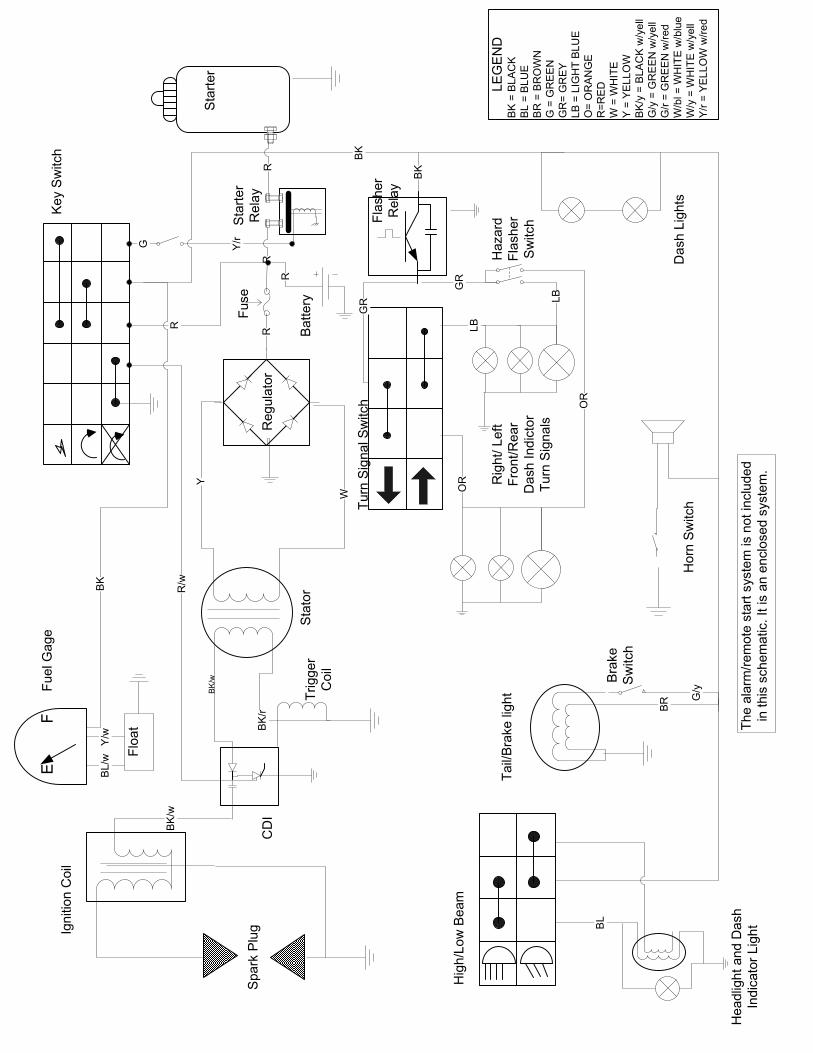
Electrical Schematic ........................................................................................36
Chapter 4 .............................................................................37
Engine ............................................................................................................37 Engine Trouble Shooting Chart .....................................................................37 Engine Removal.............................................................................................38 Engine Disassembly.......................................................................................41 Engine Inspection...........................................................................................46 Valve Train .....................................................................................................47 Engine Reassembly........................................................................................49

Chapter 5 .............................................................................56
Drive System and Kick Start..........................................................................56 Trouble Shooting............................................................................................56 Belt Removal, Inspection, and Replacement .................................................57
Clutch System...................................................................................................58
Driver and Driven Clutch...............................................................................58 Secondary Clutch ...........................................................................................60 Kick Starter ...................................................................................................60 Kick Starter ....................................................................................................61 Gear Box ........................................................................................................62
Chapter 6 .............................................................................64
Brakes ...............................................................................................................64
Front/Rear Hydraulic Brakes .........................................................................64 Removal of Brake Line and Reservoir...........................................................66
Chapter 7 .............................................................................67
Controls.............................................................................................................67
Speedometer and Cable..................................................................................67 Adjusting the Throttle Cable..........................................................................68 Adjusting Engine RPM (Idle) ........................................................................68 Throttle Cable ................................................................................................69
Chapter 9 .............................................................................70
Suspension and Steering..................................................................................70
Rear Shock .....................................................................................................70 Front Shocks ..................................................................................................71 Steering ..........................................................................................................72

Chapter 1
General Specifications
Initial Set-Up Information Transmission Gear Oil Use 5 ounces of a multi-grade motor oil SAE 90 or 85W-140. Break-In Procedure To insure maximum durability and optimal performance and to avoid engine damage, do not operate Eagle and Z-Bike at more than half throttle for the first three hours. During the break-in period operate the vehicle at various RPM’s and do not operate the vehicle above half throttle for extended periods. Engine The Eagle and Z-Bike is a four-stroke, carbureted engine. It requires the use of a quality 10W-40 four stroke engine oil and should never be run without oil in the crankcase. Extreme damage to the motor will result. Ignition System The ignition system installed on Eagle and Z-Bike is the Computerized Digital Ignition (CDI) type. Only minimum maintenance is required for this type of system. Chassis The chassis is constructed of mild steel tubing. If any frame repairs are necessary, oxyacetylene welding can be used. If wire feed or arc welding is used, use extreme care and disconnect the battery and all other electrical devices to avoid damage, while welding.

Specifications MODEL Eagle and Z-Bike 150cc DISPLACEMENT 150cc LUBRICATION OIL PUMP TRANSMISSION AUTOMATIC (C.V.T. V-BELT) SPARK PLUG NGK BATTERY 12V-9ah FUEL TANK 1.19 Gallons SEAT HEIGHT 30 inches WHEEL BASE 49.6 inches CLAIMED DRY WEIGHT pounds FRONT BRAKE Hydraulic Disk REAR BRAKE Drum/(Some models do have hydraulic disk in the rear) FRONT SUSPENSION OIL DAMPED, 50cc’s of number 3 oil REAR SUSPENSION OIL DAMPED FRONT TIRE Front 110/80-10 REAR TIRE Rear 110/80-11 *SPECIFICATIONS SUBJECT TO CHANGE WITHOUT ANY NOTICE. *
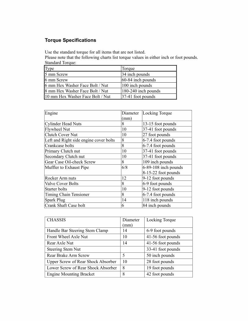
Torque Specifications Use the standard torque for all items that are not listed. Please note that the following charts list torque values in either inch or foot pounds. Standard Torque: Type Torque 5 mm Screw 34 inch pounds 6 mm Screw 60-84 inch pounds 6 mm Hex Washer Face Bolt / Nut 100 inch pounds 8 mm Hex Washer Face Bolt / Nut 180-240 inch pounds 10 mm Hex Washer Face Bolt / Nut 37-41 foot pounds Engine Diameter
(mm) Locking Torque
Cylinder Head Nuts 8 13-15 foot pounds Flywheel Nut 10 37-41 foot pounds Clutch Cover Nut 10 27 foot pounds Left and Right side engine cover bolts 8 6-7.4 foot pounds Crankcase bolts 8 6-7.4 foot pounds Primary Clutch nut 10 37-41 foot pounds Secondary Clutch nut 10 37-41 foot pounds Gear Case Oil-check Screw 8 109 inch pounds Muffler to Exhaust Pipe 6/8 6-89-108 inch pounds
8-15-22 foot pounds Rocker Arm nuts 12 9-12 foot pounds Valve Cover Bolts 8 6-9 foot pounds Starter bolts 10 9-12 foot pounds Timing Chain Tensioner 8 6-7.4 foot pounds Spark Plug 14 118 inch pounds Crank Shaft Case bolt 6 84 inch pounds CHASSIS Diameter
(mm) Locking Torque
Handle Bar Steering Stem Clamp 14 6-9 foot pounds Front Wheel Axle Nut 10 41-56 foot pounds Rear Axle Nut 14 41-56 foot pounds Steering Stem Nut 33-41 foot pounds Rear Brake Arm Screw 5 50 inch pounds Upper Screw of Rear Shock Absorber 10 28 foot pounds Lower Screw of Rear Shock Absorber 8 19 foot pounds Engine Mounting Bracket 8 42 foot pounds

Service and Adjustment Intervals The following service and adjustment charts are for general riding only. If the Eagle and Z-Bike is used in dusty, wet, or other extreme conditions, the service intervals should be increased to avoid damage to the equipment. 1. “○” equals when item should be checked. 2. “☆” equals when the part should be replaced or serviced.
Service Time (month) Service Items Before riding
1st Time
Every 6 mo.
Every 12 mo.
Item To Do Remarks
Operating Device Handle-Bar- check for play ○ ○ ○ Wheels- Right/left turn round angle ○ Brake- Play Test Ride Adjust
○ ○ ○
○
○ ○ ○
○ ○ ○
Play Handle , handle front 1/8” – ¼”
Brake Fluid ○ ○ ○ Fill with DOT 4 approved brake fluid
Cables- Loose Connections, broken or pinched cables
○ ○ ○
(mm) Front Rear Standard diameter
85 130 Brake Hub wear limits
○
Max wear limits 85.5 130.7

Service Time (month) Service Items Before riding
1st Time
Every 6 mo.
Every 12 mo.
Item To Do Remarks
Riding Device cont..
Tire
Normal Max.
Tire Pressure ○ ○ ○ ○
Min. Tires Wear
○ ○ ○ Tread Depth--- front wheel till 3 mm Rear wheel till 3 mm
Wheel bolt & nut ○
○
○
Blocking torque Front wheel – 41-56 Foot pounds Rear wheel – 41-56 Foot pounds
Tightness of front bearing ○ Tightness of rear bearing ○ Shock Absorber Spring - damage ○ ○ ○ - oil leakage or damage ○ ○ Power transmission device Gear Box ○ ○ SAE 90 or 85W-140 Electric Equipment Spark plug ○ ○ Spark plug gap 0.024-0.028 in. (0.6~0.7
mm) Battery terminal ○ Electrical wiring– loose connections, pinched or broken wires
○
Instrument Panel ○ Turn Signals ○ Brake/Tail Light ○ Head Light ○ Horn ○
The Rider should check these items for proper operation before each use to ensure the safety of the rider.

Service Items Service Time Item To Do: Remarks Before
riding 1st Time
Every6 mo.
Every 12 mo.
Starting & abnormal noise Low speed & accelerating Exhaust Air filter
○ ○
○ ○ ○ ○
○ ○ ○ ○
Idle : 1800±100 rpm
Lubrication System Oil and oil filter ○ ○ ☆ ☆ Check the oil level Change oil and
filter after 5 hours of use
Oil leakage ○ ○ ○ ○ Fuel System Fuel filter is dirty / Clogged ☆ Leakage of fuel ○ ○ ○ Throttle & choke operation ○ ○ Fuel Lines ○ ○ Exhaust pipe & muffler Loose or damaged components ○ Muffler operation ○ Cleaning combustion chamber , exhaust pipe , and carbon build-up in muffler
Every 2 years
DRIVE CHAIN and/or Belt Check the tension of the drive chain/belt ○ ○ Tolerance: 10~20mm Others - greasing Joints ○ ○

Air Filter The air filter inside the air filter housing must be kept clean to provide good engine performance. If the Eagle and Z-Bike is used under normal conditions, service the filter at the intervals specified. If operated in dusty, wet, or muddy conditions inspect and service the filter more frequently. Use the following procedure to remove the filter and inspect and/or clean it. Also check the mounting clamps for the air intake tube.
Eagle
1. To access the air filter, lift seat and remove the screws holding the cover in place.
Z-Bike 1. Remove the screws that hold the filter cover to the
filter base housing
2. Remove the 2 screws that hold the air filter in place, remove the filter.

3. Clean the prefilter using hot soapy water. Rinse and squeeze dry.
Failure to inspect the air filter frequently can damage the engine. If the Eagle and Z-Bike is used in dusty, wet, or muddy conditions, proper maintenance of
the air filter is a must for proper operation of the unit.
A torn air filter can cause damage to the engine. Dirt and dust may get inside the engine if the element is torn. Carefully examine the element for tears
before and after cleaning it. Replace the element with a new one if it is torn. Clean any dirt or debris from inside the air cleaner box. Be sure no dirt enters the air intake tube or carburetor. Install the air filter and cover. Place the filter in the air filter housing making sure it is properly seated. Tighten all the screws to secure the cover Install air filter housing and secure with the two cap screws
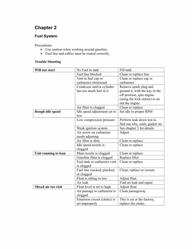
Chapter 2 Fuel System Precautions:
Use caution when working around gasoline. Fuel line and cables must be routed correctly.
Trouble Shooting Will not start No Fuel in tank Fill tank Fuel line blocked Clean or replace line Vent in fuel cap or
carburetor obstructed Clean or replace cap or carburetor
Crankcase and/or cylinder has too much fuel in it
Remove spark plug and ground it, with the key in the off position, spin engine (using the kick starter) to air out the engine
Air filter is clogged Clean or replace Rough idle speed Idle speed adjustment set to
low. Set idle to proper RPM
Low compression pressure Perform leak down test to find out why, seals, gasket etc
Weak ignition system See chapter 3 for details Air screw on carburetor
needs adjusting Adjust
Air filter is dirty Clean or replace Idle speed nozzle is
clogged Clean or replace
Unit running to lean Main nozzle is clogged Clean or replace Gasoline filter is clogged Replace filter Fuel tank or carburetor vent
is clogged Clean or replace
Fuel line cracked, pinched, or clogged
Clean, replace or reroute
Float is sitting to low. Adjust float Air leak Find air leak and repair Mixed air too rich Float level is set to high Adjust float Air passage to carburetor is
clogged Clean passageway
Emulsion circuit (choke) is set improperly
This is set at the factory, replace the choke.

Carburetor Removal 1. Disconnect ground wire from battery. 2. Remove the storage compartment. 3. Disconnect the fuel line from fuel shut off
valve.
*Note: Fuel supply has an auto on/off, however; lightly pinch the fuel lines to ensure that fuel will not leak.
4. Drain carburetor by loosening the screw on
the bottom of the bowl. 5. Disconnect wires for the automatic choke.
Vacuum Line
Fuel Line out
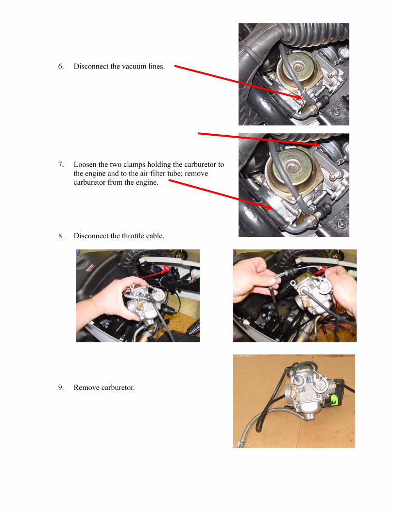
6. Disconnect the vacuum lines. 7. Loosen the two clamps holding the carburetor to
the engine and to the air filter tube; remove carburetor from the engine.
8. Disconnect the throttle cable. 9. Remove carburetor.

Carburetor Disassembly While disassembling the carburetor, pay attention to any foreign material that you may find inside the carburetor; this can help in the diagnosis of the unit. 1. Clean outside of carburetor of dirt and other debris. 2. Remove float bowl; watch out for the bowl gasket. 3. Remove the float pin, float, inlet needle, and inlet seat. 4. Remove the three jets from the float chamber of the
carburetor body. 5. Remove the slide; use caution when removing the slide so as
not to scratch it or rip the diaphragm. 6. Remove the needle jet from the slide.

7. Remove the electric choke and the choke circuit plate.
Use caution with the rubber gasket. 8. Remove the power valve watch for the spring and
diaphragm. 9. Before removing the pilot air screw, turn the screw in,
counting the number of turns. Remove the pilot air and the idle adjustment screws from the side of the carburetor.
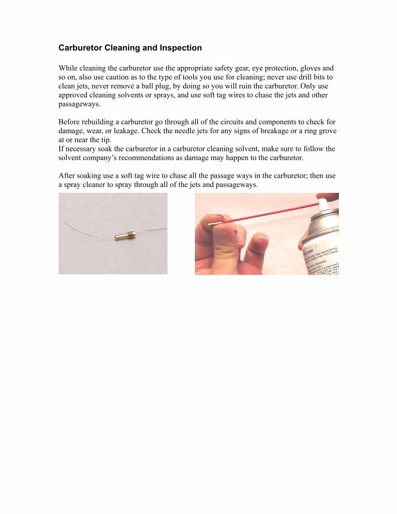
Carburetor Cleaning and Inspection While cleaning the carburetor use the appropriate safety gear, eye protection, gloves and so on, also use caution as to the type of tools you use for cleaning; never use drill bits to clean jets, never remove a ball plug, by doing so you will ruin the carburetor. Only use approved cleaning solvents or sprays, and use soft tag wires to chase the jets and other passageways. Before rebuilding a carburetor go through all of the circuits and components to check for damage, wear, or leakage. Check the needle jets for any signs of breakage or a ring grove at or near the tip. If necessary soak the carburetor in a carburetor cleaning solvent, make sure to follow the solvent company’s recommendations as damage may happen to the carburetor. After soaking use a soft tag wire to chase all the passage ways in the carburetor; then use a spray cleaner to spray through all of the jets and passageways.

Carburetor Reassembly
1. Start by installing of the jets into the float area of the carburetor. Verify that the jets are being installed in the correct position.
2. Place the inlet-needle onto the float then install float. Make sure to push the fulcrum pin in all of the way.
3. Adjust the float level; the float should sit just below level.
Metal Tab

4. Install bowl gasket and bowl.
5. Install electric choke.
1
3
2
4
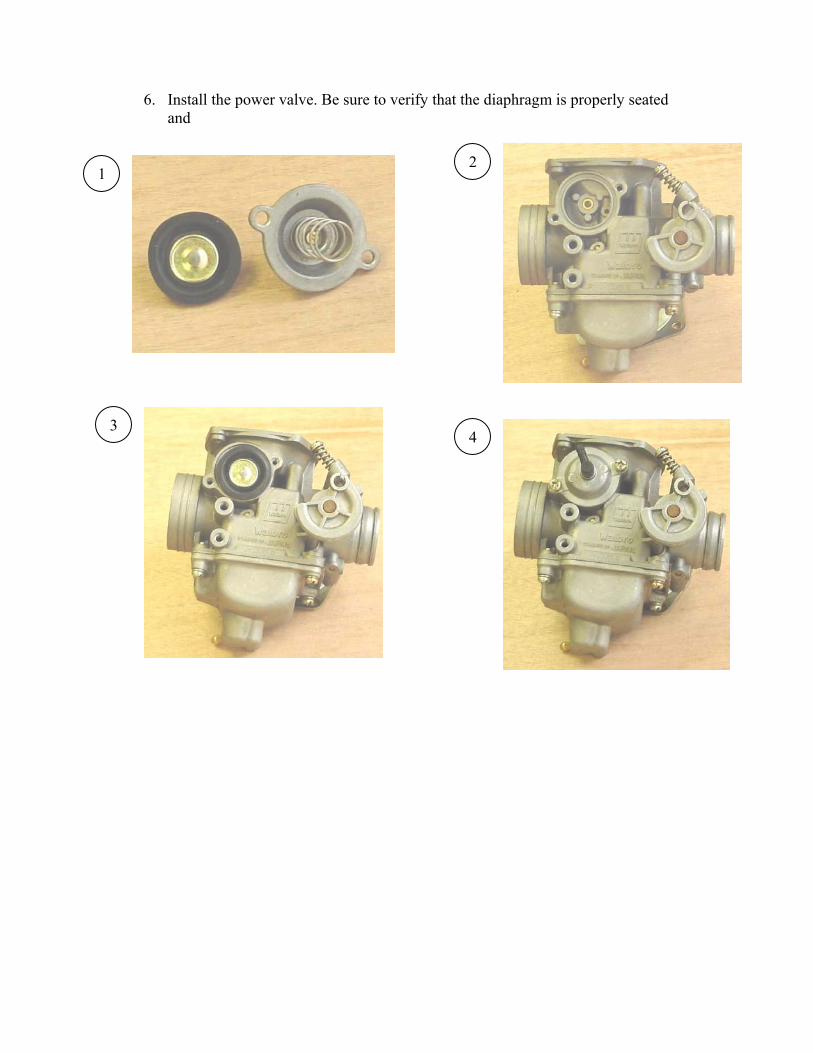
6. Install the power valve. Be sure to verify that the diaphragm is properly seated
and
1
43
2

7. Install throttle slide, spring, and cover. Make sure that the slide moves up and down freely.
8. Install pilot air screw; turn it in until seated, then back out 1-1/2 times.
9. Install the cap. make sure to diaphragm is properly seated
1
3 4
2

Fuel Tank, Float Sensor, Line, Shut-Off Valve and Filter Fuel Tank and Fuel Level Sensor Removal
Remember fuel is flammable use caution!
Drain fuel tank before servicing the tank. To gain access to the fuel tank you must first remove the body panels on the back of the Eagle and Z-Bike. See the pictures below for the sequence of removal. *Note to remove the fuel level sensor, the same steps must be followed.
1. Remove the body panels to get to the fuel tank. See chapter 7 for more details.
2. Disconnect the fuel line and the fuel level sending unit
3. Remove the front two bolts first then the rear two. Note that the tank will need to be supported.
4. Slide the tank out the rear of the bike.
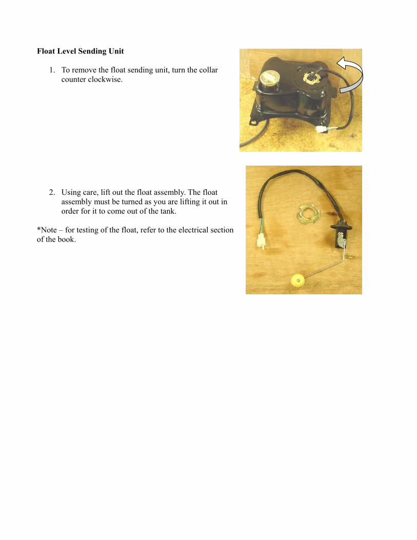
Float Level Sending Unit
1. To remove the float sending unit, turn the collar counter clockwise.
2. Using care, lift out the float assembly. The float assembly must be turned as you are lifting it out in order for it to come out of the tank.
*Note – for testing of the float, refer to the electrical section of the book.
Fuel Line, Filter and Fuel Shut-off Valve Fuel Line-When replacing the fuel line, make sure to use a quality line and route the line to the proper connecters. Fuel filter- Make sure to install the filter so that the flow is in the correct direction. The fuel filter is located on the left side near the fuel tank. To access it look behind the grey body molding and it should be visible. Removing the body panel may be done for easier access. Fuel Shut Off Valve – The shut-off valve is vacuum operated; it gets the vacuum from the intake manifold. Be sure to check the lines if the shut-off valve is not operating properly. To test the shut-off valve, apply a negative pressure (vacuum) to the valve and fuel should flow freely. If not, replace the valve.

Chapter 3
Electrical When testing continuity of a circuit, always make sure that the circuit has been
isolated from any form of electricity. POSSIBLE IRREPARABLE DAMAGE TO YOUR METER OR YOURSELF MAY OCCUR if you do not follow this
advice.
Do not unplug electrical components from the wire harness while the unit is running. This could cause a spark or a voltage spike and damage other components such as the bridge rectifier, ignition module, light bulbs…etc. Turn the main switch to OFF before beginning any repair. When checking the Voltage, Ohms, or Amps, use the proper electrical meter, preferably a multi-meter. Make sure to be familiar with proper use of your meter; performing an amp draw test while the meter leads are hooked up wrong can result in damage to your meter and the electrical system.
Specifications IGNITION
Spark Plug Type NGK C7HSA
Spark Plug Gap 0.024-0.028 in.
Spark Plug Cap 4.5k-5k ohms
Ignition Coil Resistance
Primary
Secondary
12.5 – 13.0 ohm spade connector to ground
2.5k – 3k ohms high tension - plug cap removed - to ground
CHARGING SYSTEM
Trigger Coil
Peak voltage
Resistance
2.4-3.6V (white/red to black)
93.6-140.4 ohms (white/red to black)
Source Coil
Cranking voltage
Resistance
50 – 65 acv
100 - 150 ohms
Ignition Coil Resistance
Spark Plug Cap Resistance
Primary .1 – 13.0 ohms(orange to black)
Secondary 4K-7.5K Ohms (cap removed)
10K ohm
AC Output Peak voltage/Resistance
Peak voltage
Resistance
6.2-9.2V yellow/red to black
0.5-0.7 ohm yellow/red to black
7.4-11 .2V white to black
0.5-0.7 ohm white to black Choke Circuit Peak voltage 5.9-8.9V yellow/red to black

Trouble Shooting
Testing Electrical Components All of the electrical tests should be made using a good quality multi-meter. Please note that many factors can change the readings of a meter; temperature, the condition of the meter leads, the condition of the batteries in the meter are just a few items that can change the readings. When troubleshooting a specific component, always verify that the fuse is good, that the bulb is good, that the connections are clean and tight, that the battery is fully charged, and that all appropriate switches are activated.
No or little Electrical output
Battery is discharged Charge or replace battery
Loose or broken connection Tighten or repair wire Fuse is blown Replace fuse Regulator rectifier bad Replace regulator rectifier Stator is bad Replace stator Starter will not turn Battery is dead Charge battery Tether has been pulled out Replace tether Brake lever is not pulled in Pull lever Brake lever is pulled Brake safety switch needs
to be checked/replaced Ignition switch is on still
will not start Check switch for continuity replace if bad
Ignition switch tested good still will not start
Check the push button starter switch for current.
Fuse is bad Replace Starter is bad Check and repair or replace Starter relay Check and repair or replaceStarter turns, unit still will not start.
Choke

Trigger Coil Disconnect the connectors on the right side of the engine.
Resistance
1. Set the meter to the OHMS position.
2. Connect the red tester lead to the black with red wire; then connect the black tester lead to ground
3. The meter should read 93.6-140.4 ohms.
Source Coil Disconnect the triple-plug connector on the left side of the engine.
Voltage
1. Set the meter selector to .the A.C. Voltage position.
2. Connect the red tester lead to the black/white wire; then connect the black tester lead to ground.
3. Crank the engine over using the electric starter. The meter should read 50-65 volts A.C.
Resistance
1. Set the meter selector to the OHMS position.
2. Connect the red tester lead to the black/ yellow wire; then connect the black tester lead to the black wire.
3. The meter should read 442.6-668.4 ohms.
C.D.I. and Ignition Coil Testing the CDI is a process of elimination. Test the components around the CDI and if they are good, replace the CDI.
Disconnect the wires at the ignition coil.
Voltage 1. Set the meter selector to the D.C. Voltage position.
2. Connect the red tester lead to the black/yellow wire; then connect the black tester lead to ground.
3. Crank the engine over using the electric starter. The meter should read 6.2-9.2 volts.

Ignition Coil The ignition coil is attached to the frame under the foot rest. To access the coil you will have to remove the upper floor panel.
Primary Winding Resistance
1. Disconnect the black/yellow wire from the coil.
2. Connect the red tester lead to the orange wire (with the wire removed); then connect the black tester lead to ground.
3. The meter should read .5-13 ohms.
• NOTE: If the meter does not show as specified, replace ignition coil.
Secondary Winding Resistance
1. Connect the red tester lead to the high tension lead (plug cap removed); then connect the black tester lead to ground.
*Note- if you do not remove the spark plug cap, your readings will be off.
2. The meter should read 2500 - 3000 ohms (2.5k – 3k ohms).
*NOTE: If the meter does not show as specified, replace ignition coil.
Spark Plug Cap Resistance
1. With the cap removed from the spark plug wire, connect the red tester lead to one end of the cap; then connect the black tester lead to the other end of the cap.
2. The meter should read 4500 - 5000 ohms (4.5k – 5k ohms).
* NOTE: If the meter does not show as specified, replace the spark plug cap.
Magneto Assembly Removing the Magneto Assembly
1. Disconnect the battery
2. Remove the flywheel from the engine. Always use the proper puller for the job. See the engine section for more details.
CAUTION: do not use a hammer to remove the flywheel; the crankshaft and other internal components will be damaged!
3. Remove the stator and timing sensor from the stator plate.
Installing the Magneto Assembly
1. Install the timing sensor and stator onto the stator plate. Apply Loctite to the Phillips-head cap screws. Tighten securely.
2. Install the flywheel. Torque the flywheel nut to 20 foot pounds

Choke Circuit The electric choke works by using heat and a thermo-coupler. As the thermo-coupler heats up the element inside it expands pushing out the plunger to seat the needle against the seat in the choke passageway.
*Note- as long as the engine is running, current is going to the choke heating up the element causing the needle to seat.
1. Disconnect the black double-plug connector on the left side on the engine.
2. Remove the two screws that hold the choke in place and remove the choke.
3. Using a set of small jumper wires, connect a 12v battery to the leads of the choke assembly. After 5-10 minutes, the plunger should be pushed out. Let the choke cool and the plunger should retract.
Voltage 1. Set the meter selector to the D.C. Voltage position.
2. Connect the red tester lead to the yellow/red wire; then connect the black tester lead to the ground.
3. Crank the engine over using the electric starter. The meter should read 5.9-8.9 volts.
Resistance 1. Set the meter selector to the ohms position.
2. Connect the red tester lead to the yellow/red wire; then connect the black tester lead to the ground.
3. The meter should read 18-25 ohms.
Choke On
Choke Off
Battery
*Safety Note Battery electrolyte contains sulfuric acid, which can cause severe burns. Avoid contact with skin, eyes, or clothing. If you come into contact with sulfuric acid, flush the area with water and if needed seek medical attention. Proper maintenance of a battery will help ensure the battery will last its rated lifetime. Keeping the battery fully charged, especially during extended periods of non use will help the battery last longer. Clean and tight terminals will also help its longevity. Before installing a new battery, fill it with electrolyte and let stand for 20 minutes before installing the caps, and then charge the battery following the battery manufactures instructions. Do not use quick charge unless it is urgent. The battery needs to be taken out of the vehicle while charging. CHARGING
The battery manufacturers charging instructions take precedence and need to be followed before following through with this procedure.
1. Remove the battery from the ATV.
Remove the negative cable first; then remove the positive cable.
Do not charge the battery while it is in the ATV and the cables connected
2. Trickle-charge the battery at 1-.4 amps for 4-6 hours.
3. Place the battery into position in the ATV and secure.
4. Connect cables to the proper terminals: positive cable to the positive terminal (+) and negative cable to the negative terminal (-). Connect the negative cable last.
Testing Voltage
2. Connect the red tester lead to the positive battery
3. The meter must show 12.8 volts or more.
4. Reconnect the positive and negative terminals.

Brake Light Switch The switch connector is the two individual single connectors located under the left-front fender.
•NOTE: The ignition switch must be in the ON position.
Voltage
Wiring Harness Connector
1. Set the meter selector to the D.C. Voltage position; then turn the ignition switch to the ON position.
2. Connect the red tester lead to the green/yellow wire; then connect the black tester lead to ground.
3. The meter should show battery voltage. If battery voltage is not present, troubleshoot the battery, fuse, switch, or the main wiring harness. If the meter shows battery voltage, the main wiring harness is good; test the switch and other components of the switch, the connector, and the switch wiring harness for resistance.
Resistance, Brake Light Switch Connector
*NOTE: The brake switch must be disconnected from the wire harness to prevent damage to your meter and to get the proper reading.
Repeat this step for both brake levers.
1. Set the meter selector to the OHMS position.
2. Connect the test leads to the two wires coming out of the brake switch (polarity is not important).
3. When the lever is compressed, the meter should read less than 1 ohm.
*NOTE: If the meter shows more than 1 ohm of resistance, troubleshoot or replace the switch/component, the connector, or the switch.
Handlebar Control Switches The connector is the red one in front of the steering post. The connector is accessible in headlight cover.
*NOTE: These tests should be made on the top side of the connector.
Starter Button Resistance
1. Set the meter selector to the Diode position
* Note- if your meter does not have a diode tester you can use the standard ohm setting but you must pay attention to which end you have the positive tester lead hooked to. If you do not get the desired reading change the leads around.
2. Connect the red tester lead to the orange/white wire; then connect the black tester lead to the yellow/green wire.
3. With the starter button depressed, the meter should read 0.5-0.7 ohm.
4. With the starter button released, the meter must show an open circuit.
5. Connect the red tester lead to the yellow/green wire; then connect the black tester lead to the orange/white wire
6. With the starter button depressed, the meter must show an open circuit.
*NOTE: If the meter does not show as specified, replace the switch/component, connector, or switch harness.
Starter Motor Removing and Disassembly
*Note – this section is provided for testing only; the starter is only available as an assembly.
1. Disconnect the battery.
Always disconnect the negative battery cable from the battery first; then disconnect the positive cable.
2. Remove the starter motor from the engine.
3. Remove the nut securing the positive cable to the starter; then remove the cable from the starter. Account for the o-ring that goes on the end of the starter.
4. Remove the two cap screws securing the main housing to the end housing; then remove the main housing. Account for two washers that go onto the bolts and the o-ring that goes between the main housing and the end cap.
5. Remove the two brushes and armature from the end housing.
Inspection
1. Check the armature windings for damage.
2. Check the brushes for wear.
*Note if the starter needs to be serviced, unless it is minor like the brushes, replace the starter as an assembly

Assembling and Installing
1. Install the armature and brushes into the end housing. 2. Install the o-ring and main housing over the end housing and secure with two cap screws coated with red Loctite #271. Tighten the cap screws securely. 3. Install the starter motor
Voltage Regulator Rectifier The regulator is located behind the front cowling. Its function is to change AC current to DC current then reduces the voltage from 28 volts AC (or higher) to 12.8 to 13.5 volts DC.
1. Set the meter selector to the AC Volt position. 2. Test between the yellow and white wires. 3. With the engine running at a constant 5000 RPM, the meter should read at least (minimum) 26-28 volts AC. 4. If the voltage is to low, replace the stator. 5. Set the volt meter to DC volts. At the voltage regulator, test from the red wire to ground. The reading should be between 13-14.5 volts DC. 6. If the reading is too high or to low replace the voltage regulator.
Ignition Timing The ignition timing cannot be adjusted; however, items like the flywheel key, flywheel magnets, and stator can affect the timing of the engine.
Horn
To access the horn, the front cowling must be removed. Battery voltage should be present at the horn (green w/red wire) while the key is turned on. Test the green w/red wire to ground and you should read battery voltage. The green wire goes to the horn switch, through the switch when depressed to ground.
Turn Signals To test the turn signal circuit, remove the headlight cowling to gain access to the components. Power (battery voltage) is supplied to the signals through the grey wire that goes to the flasher relay. It then comes out the flasher relay to the turn signal switch. At this point the power is split to the two sides. When the switch is activated power goes to the designated signal until the switch is turned off.
The flasher relay is located inside the headlight housing. Remove the four screws that are around the speedometer cover. When the headlight cowling is removed, the flasher relay will be located atop the speedometer housing.
The four way flasher works the same as the individual turn signals except that it powers both turn signals instead of one.

Head and Tail Light The wiring for the head and tail lights is located inside the handlebar and headlight cowling. Find the connector with the blue wire coming out of it. This will lead up to the head light switch (high/low beam). The yellow wire is the power supply going into the switch.
Fuel Level Sending Unit To access the fuel level sensor you must remove the storage compartment under the seat and remove the sending from the fuel tank. Test the continuity between the three wires coming out of the sensor. As you move the float the continuity should change, see chart below for values.
Ignition Switch To access the ignition switch remove the front cowling. Disconnect the white connector and do an ohms test according to the following chart.
Alarm System The alarm system is a self contained system and very little testing can be performed. If the alarm will not arm, check the battery in the remote and the fuse on the alarm box. To disable the alarm system, disconnect the fuse on the alarm box. Note that this will also disable the remote start as well.
Float in the up position
Float in the down Position
Green & Yellow w/wht
30-60 ohms
Green & Yellow w/wht
600-1500 ohms
Green & Blue w/wht
600-1500 ohms
Green & Blue w/wht
30-60 ohms
Color
Position
Green Black W/wht
Black Red
12vdc in
Off
On
Green
Yellow w/wht
Blue w/wht
BK
/r
Y
W
RR
R
R
BK
/w
Y/r
RR
/w
BK
BK
GR
OR
LB
EF
Floa
t
BK
BL/
wY
/w
BL
G/y
BR
Tail/
Bra
ke li
ght
Hig
h/Lo
w B
eam
Hea
dlig
ht a
nd D
ash
Indi
cato
r Lig
ht
Hor
n Sw
itchTu
rn S
igna
l Sw
itch
Flas
her
Rel
ay
Rig
ht/ L
eft
Fron
t/Rea
rD
ash
Indi
ctor
Tu
rn S
igna
ls
Sta
rter
Sta
rter
Rel
ayR
egul
ator
Key
Sw
itch
Bat
tery
Sta
tor
Fuel
Gag
eIg
nitio
n C
oil
Spa
rk P
lug
CD
I
Trig
ger
Coi
l
Bra
ke
Switc
h
Das
h Li
ghts
Fuse
GR
OR
LB
Haz
ard
Flas
her
Switc
h
BK
/w
G
LEG
END
BK
= B
LAC
KB
L =
BLU
EB
R =
BR
OW
NG
= G
RE
EN
GR
= G
RE
YLB
= L
IGH
T B
LUE
O=
OR
AN
GE
R=R
ED
W =
WH
ITE
Y =
YE
LLO
WB
K/y
= B
LAC
K w
/yel
lG
/y =
GR
EE
N w
/yel
lG
/r =
GR
EE
N w
/red
W/b
l = W
HIT
E w
/blu
eW
/y =
WH
ITE
w/y
ell
Y/r
= Y
ELL
OW
w/re
d
The
alar
m/re
mot
e st
art s
yste
m is
not
incl
uded
in
this
sch
emat
ic. I
t is
an e
nclo
sed
syst
em.
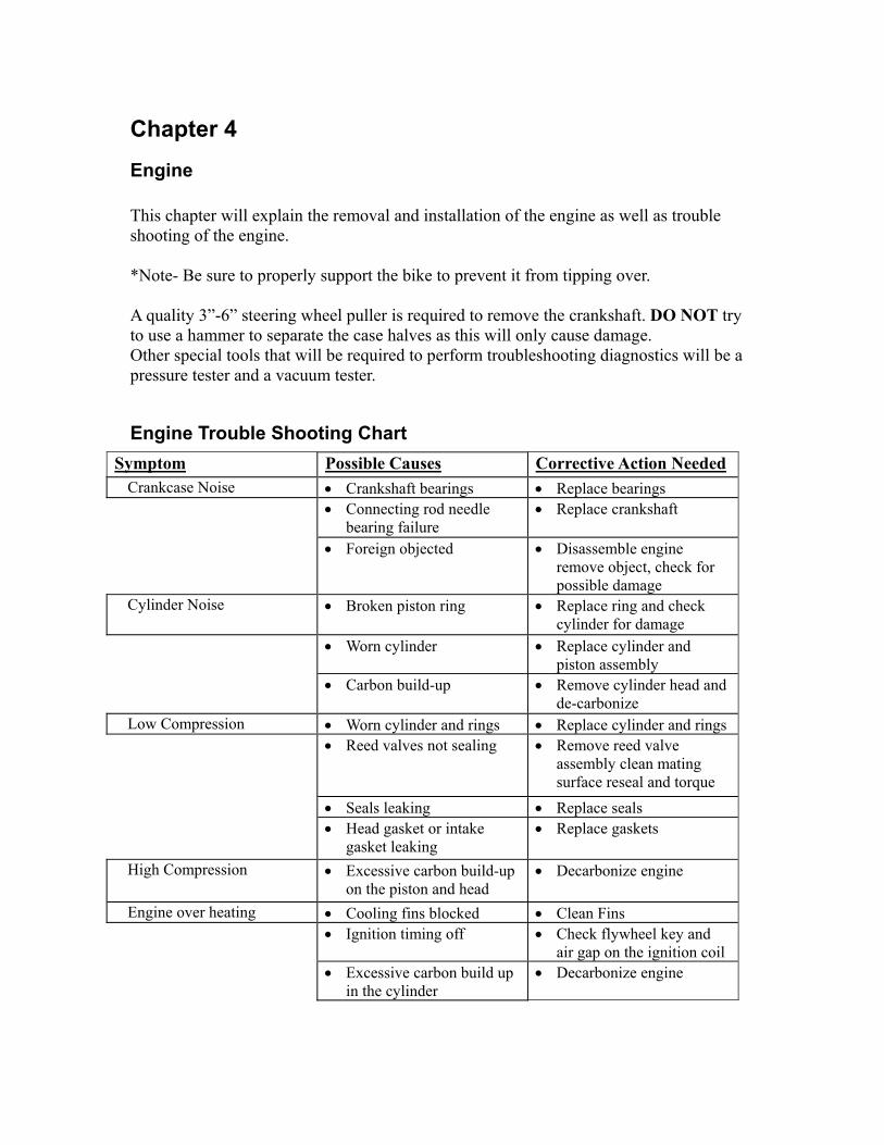
Chapter 4 Engine This chapter will explain the removal and installation of the engine as well as trouble shooting of the engine. *Note- Be sure to properly support the bike to prevent it from tipping over. A quality 3”-6” steering wheel puller is required to remove the crankshaft. DO NOT try to use a hammer to separate the case halves as this will only cause damage. Other special tools that will be required to perform troubleshooting diagnostics will be a pressure tester and a vacuum tester.
Engine Trouble Shooting ChartSymptom Possible Causes Corrective Action Needed
Crankcase Noise • Crankshaft bearings • Replace bearings • Connecting rod needle
bearing failure • Replace crankshaft
• Foreign objected • Disassemble engine remove object, check for possible damage
Cylinder Noise • Broken piston ring • Replace ring and check cylinder for damage
• Worn cylinder • Replace cylinder and piston assembly
• Carbon build-up • Remove cylinder head and de-carbonize
Low Compression • Worn cylinder and rings • Replace cylinder and rings • Reed valves not sealing • Remove reed valve
assembly clean mating surface reseal and torque
• Seals leaking • Replace seals • Head gasket or intake
gasket leaking • Replace gaskets
High Compression • Excessive carbon build-up on the piston and head
• Decarbonize engine
Engine over heating • Cooling fins blocked • Clean Fins • Ignition timing off • Check flywheel key and
air gap on the ignition coil • Excessive carbon build up
in the cylinder • Decarbonize engine

Engine Removal The engine is an integrated part of the suspension of the bike; it is the rear swing arm. Proper support of the frame will be necessary to remove the engine.
1. Disconnect and remove battery; also disconnect all electrical connections. *Note the path of the wires and where they connect. Chapter 3
2. Drain Engine oil
3. Remove fuel lines from the carburetor and disconnect the air filter boot.
Gasoline is flammable KEEP AWAY FROM SPARKS!

4. Remove the bolts that hold on the muffler.
5. Removal of the rear wheel is not required to remove the engine; however, it may be easier to remove it at this point. Remove the lock that holds the tire assembly in place.
6. Remove the engine mounting bolts. There is one that goes across the top of the
engine and two on the rear of the engine (rear shocks). Some models may only have one rear shock.
*Note- Make sure to properly support the engine to prevent it from falling

7. Remove engine from the frame.

Engine Disassembly
1. Remove the rubber and hard plastic cooling shroud from around the engine.
2. Remove the cooling fan and flywheel using the proper puller. Tip: to remove the flywheel nut, put some scrap recoil rope into the cylinder through the spark plug hole; this will act as a piston stop.
Do not hit the crankshaft with a hammer to remove the flywheel, crankshaft and
bearing damage will occur.
3. Remove the stator assembly. Note: DO NOT remove the trigger coil from the stator it is timed at the factory!
4. Remove the starter assembly.

5. Remove the right side crankcase cover. This will expose the starter clutch and oil pump.
6. Remove the large starter gear. Make sure that the bearing comes out with the starter gear.
7. Remove the starter clutch (sprag gear)
8. Remove the small starter gear.
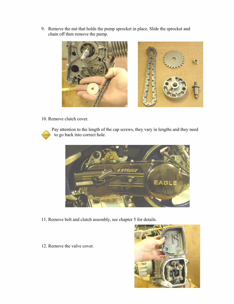
9. Remove the nut that holds the pump sprocket in place. Slide the sprocket and
chain off then remove the pump.
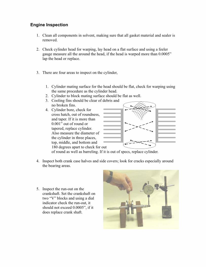
10. Remove clutch cover.
Pay attention to the length of the cap screws, they vary in lengths and they need to go back into correct hole.
11. Remove belt and clutch assembly, see chapter 5 for details.
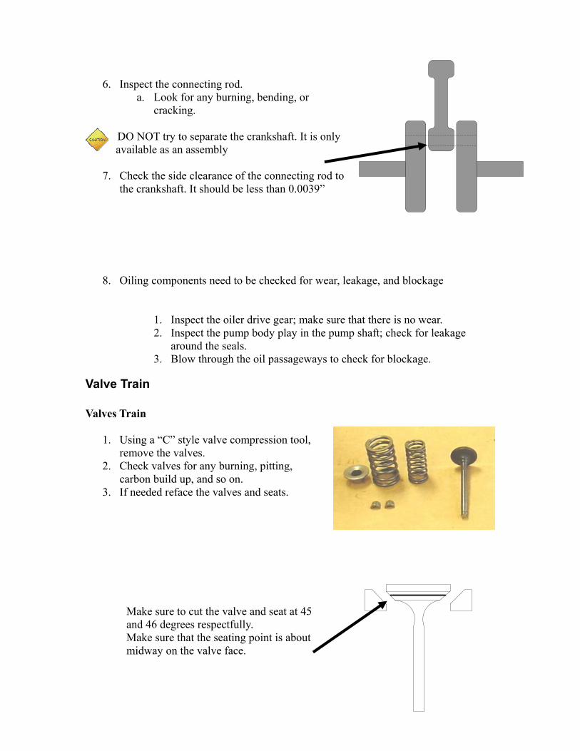
12. Remove the valve cover.

13. Loosen the jam nut on the valve adjusting screw and back off the adjusting screw to relieve tension then remove the nuts that hold the rocker arm assembly in place.
14. With the rocker arms out of the way, tilt the cam shaft enough so that the chain will can be removed. Then lift off the cylinder head assembly.
15. Remove the cylinder assembly.
Make sure to protect the piston from hitting anything after the
cylinder is removed.
16. Remove piston from connecting rod by removing the piston pin retainer clips.

17. Separate the crankcase
DO NOT use a hammer to separate the crankcase as this will cause damage to the crankshaft and
bearings!
18. Remove crankshaft from crankcase housing; Again DO NOT use a hammer. *Note – the timing chain must be removed from the sprocket before the crankshaft can be removed. Once crankshaft is out of the case half, remove the timing chain.
Engine Inspection
1. Clean all components in solvent, making sure that all gasket material and sealer is removed.
2. Check cylinder head for warping, lay head on a flat surface and using a feeler
gauge measure all the around the head, if the head is warped more than 0.0005” lap the head or replace.
3. There are four areas to inspect on the cylinder,
1. Cylinder mating surface for the head should be flat, check for warping using the same procedure as the cylinder head.
2. Cylinder to block mating surface should be flat as well. 3. Cooling fins should be clear of debris and
no broken fins. 4. Cylinder bore, check for
cross hatch, out of roundness, and taper. If it is more than 0.001” out of round or tapered, replace cylinder. Also measure the diameter of the cylinder in three places, top, middle, and bottom and 180 degrees apart to check for out of round as well as barreling. If it is out of specs, replace cylinder.
4. Inspect both crank case halves and side covers; look for cracks especially around
the bearing areas.
5. Inspect the run-out on the crankshaft. Set the crankshaft on two “V” blocks and using a dial indicator check the run-out, it should not exceed 0.0005”, if it does replace crank shaft.
6. Inspect the connecting rod.
a. Look for any burning, bending, or cracking.
DO NOT try to separate the crankshaft. It is only available as an assembly
7. Check the side clearance of the connecting rod to
the crankshaft. It should be less than 0.0039”
8. Oiling components need to be checked for wear, leakage, and blockage
1. Inspect the oiler drive gear; make sure that there is no wear. 2. Inspect the pump body play in the pump shaft; check for leakage
around the seals. 3. Blow through the oil passageways to check for blockage.
Valve Train Valves Train
1. Using a “C” style valve compression tool, remove the valves.
2. Check valves for any burning, pitting, carbon build up, and so on.
3. If needed reface the valves and seats.
Make sure to cut the valve and seat at 45 and 46 degrees respectfully. Make sure that the seating point is about midway on the valve face.

4. Check the valve stem for wear and straightness
5. Check the valve guide for wear, the clearance between the guide and stem. The max wear limit is .0035”
6. Inspect the rocker arms and pivots for any signs of wear.
7. Inspect the cam shaft for any signs of wear.
8. Inspect the cam gear and chain for broken teeth and damaged or stretched chain.
9. Inspect the valve springs that they are of the same height.

Engine Reassembly
1. Install seals- Install retaining ring on the drive side crankcase, then using a seal driver or socket install the seal until it seats against the retaining ring. On the ignition side crankcase, install seal using a driver or socket.
2. Lubricate all the bearings on the crankshaft and seal surfaces using four cycle oil.
3. Install the piston onto the connecting rod. Make sure that the piston is oriented correctly onto the crankshaft. Use oil on the piston pin.
When installing the piston pin retainers, make sure that the opening is at the 6 o’clock position.
4. Install the crankshaft into the housing. While sliding the crankshaft into crankcase, position the timing chain so that the crankshaft will slide through the timing chain.

Do not use sealer on the gasket as this will change the end play of the crankshaft.
5. Install ignition side crankcase onto the crankshaft.. Apply a small amount of lock-
tight to the bolt threads and torque to 84 inch pounds. Use a seal protector as a caution so as not to damage the seals.
DO NOT use the crankcase bolts or a hammer to assemble the two halves together.
6. Install the seal retainer on the ignition side.
7. Install the timing chain guides. One is bolted into place and the other sits in a slot in the crankcase.
8. Stagger the piston ring ends so that there is at least 30 degrees between each ring. With the cylinder well lubricated, start the cylinder onto the studs. Feed the timing chain up through the cylinder and use a screwdriver to keep the chain from falling into the crankcase. Slide the cylinder over the piston assembly using caution so not to break a ring.
9. Install the head gasket and position the cylinder head onto the studs.
10. Position the piston so it is at top dead center; position the cam shaft into its cradle aligning the timing marks with the cylinder head. Install the chain. Verify the timing by rotating the crankshaft, when the piston reaches top dead center on the exhaust stroke, the exhaust valve should be almost closed and the intake

valve will be just starting to open (valve overlap).
11. Install the rocker arms and torque the nuts down to 13-15 foot pounds. Be sure to tighten the nuts down in two steps using a crisscross pattern. Be sure to lubricate the rocker arms before assembly.
12. Adjust the valves to 0.002”-0.003” for both intake and exhaust.
13. Install the valve cover
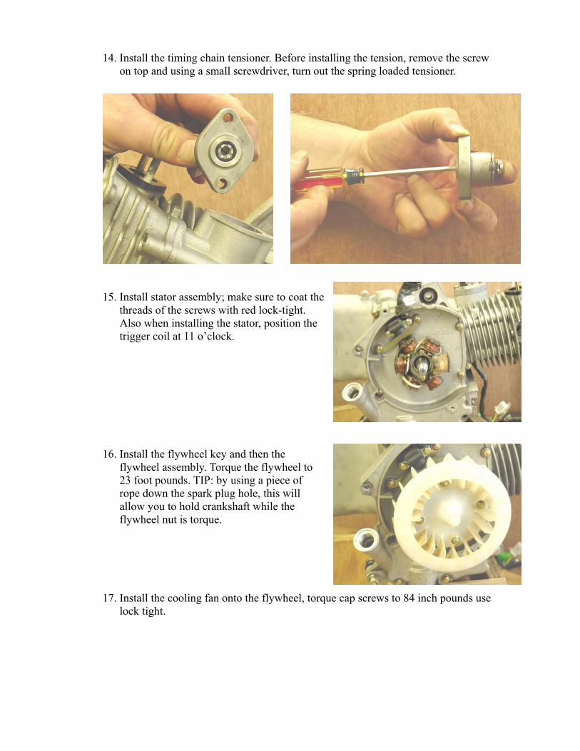
14. Install the timing chain tensioner. Before installing the tension, remove the screw on top and using a small screwdriver, turn out the spring loaded tensioner.
15. Install stator assembly; make sure to coat the threads of the screws with red lock-tight. Also when installing the stator, position the trigger coil at 11 o’clock.
16. Install the flywheel key and then the flywheel assembly. Torque the flywheel to 23 foot pounds. TIP: by using a piece of rope down the spark plug hole, this will allow you to hold crankshaft while the flywheel nut is torque.
17. Install the cooling fan onto the flywheel, torque cap screws to 84 inch pounds use lock tight.

18. Install the oil pump assembly into the crankcase. Make sure the o-rings are in place and well lubricated before installing.
19. Slide the oil pump drive chain onto the crankshaft. Slide the pump sprocket into the chain and install onto the pump. Make sure to align the D hole in the sprocket with the shape on the shaft.
20. Install the small starter gear onto the shaft. The larger gear goes to the crankcase.
21. Slide the sprag gear onto the crankshaft.

22. Lubricate then install the bearing into
the sprag gear/
23. Install the large starter gear.
24. Install the left side crankcase cover. Be sure to use a seal protector when installing the seal. Torque the side cove bolts to 84 inch pounds
When installing the bolts, pay attention to the length of the bolts.
When the bolt is placed in the hole, the height of each bolt should be the same see below picture.
25. Install the starter. Make sure to install the ground wire under the top screw.
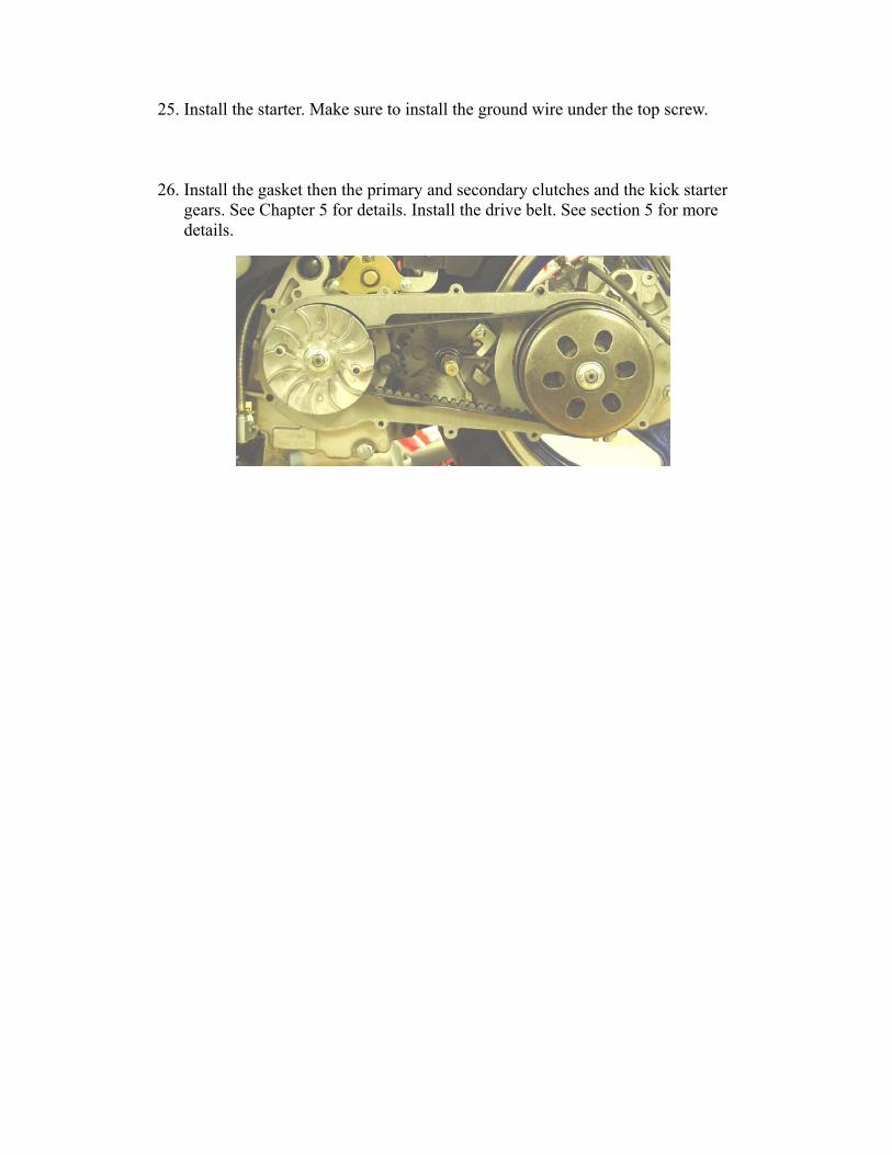
26. Install the gasket then the primary and secondary clutches and the kick starter gears. See Chapter 5 for details. Install the drive belt. See section 5 for more details.
Chapter 5 Drive System and Kick Start This chapter will consist of the adjustment, removal, disassembly, and reassembly of the following components:
• Belt Replacement • Clutch Components • Rear Axle Assembly • Kick Starter • Gear Box • Brakes
Trouble Shooting Symptom Possible Cause Solution
Will not stop Cable(s) broken or out of adjustment
Replace or adjust cable(s)
Brakes worn out or jammed
Adjust or replace brakes
Unit will not move Transmission gears broken Remove and replace necessary parts
Clutch driver or driven unit not working
Remove and repair or replace necessary parts
Belt broken or jammed Remove belt and replace if necessary
Axle or differential broken Remove and replace -Brakes locked • Lever is locked in place
or bent • Jammed cable • Brake shoes or pads are
jammed
• Replace lever • Replace cable • Replace pads or shoes

Belt Removal, Inspection, and Replacement To remove the belt you must first remove the belt cover. With the cover off, remove the nut that holds the driver clutch together and slide the belt off. Inspect the belt for any signs of wear, cracking, or stretching. If any of these signs appear the belt will have to be replaced. While the belt is off inspect the pulleys for any signs of wear as well. To install the belt, reverse the disassembly instructions.
Clutch System
Driver and Driven Clutch Removal, Inspection, and Reassembly The removal of the clutch driver will require the removal of the left belt cover. Disconnect the spark plug wire for safety
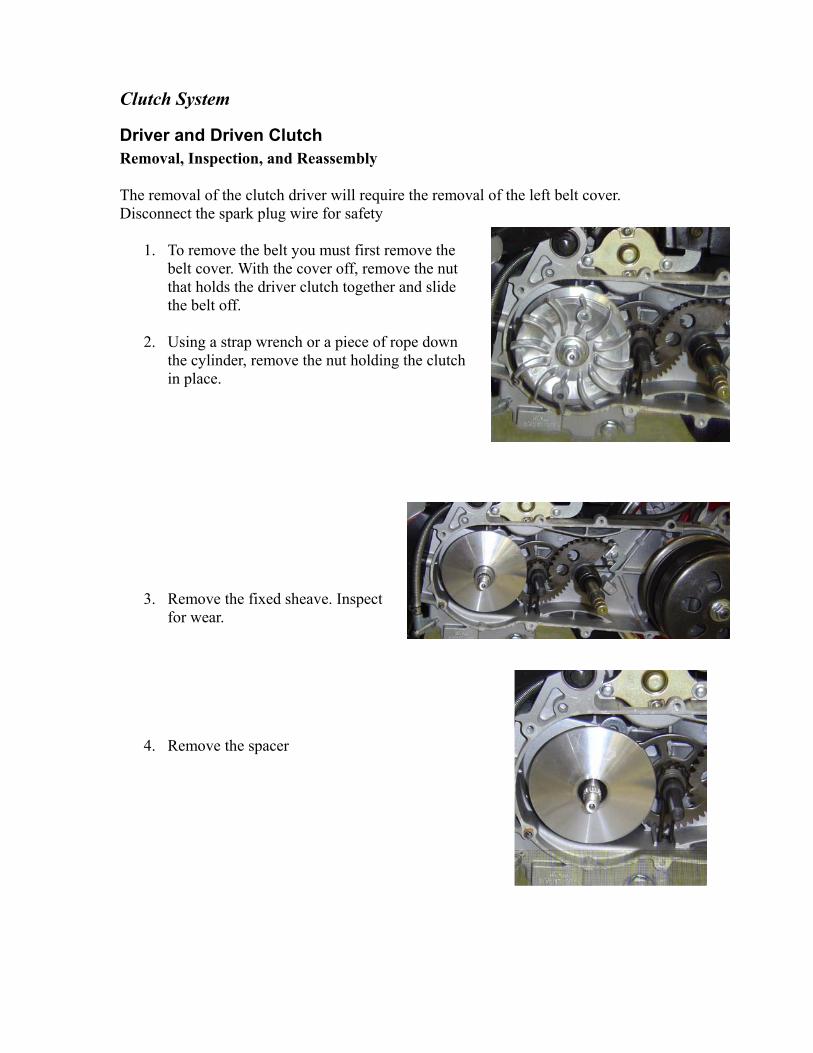
1. To remove the belt you must first remove the belt cover. With the cover off, remove the nut that holds the driver clutch together and slide the belt off.
2. Using a strap wrench or a piece of rope down
the cylinder, remove the nut holding the clutch in place.
3. Remove the fixed sheave. Inspect for wear.
4. Remove the spacer

5. Lift off the movable sheave and rollers as an assembly. Once off separate the
roller plate from the sheave; inspect rollers for wear as well as the areas that the rollers ride in. Also check the face of the sheaves that the belt rides on. It needs to be smooth.
Make sure to account for all six rollers.
Reassembly Follow the disassembly procedure in the reverse order.

Secondary Clutch Follow the above steps to gain access to the clutch and pulleys. Remove the belt. Using a strap wrench, hold the clutch and remove the nut. This will allow the secondary clutch to be removed.

Kick Starter To gain access to the kick starter, the belt cover must first be removed. Once off, remove the primary clutch, belt, and the gasket.
1. Before removing the shafts, not the alignment marks.
2. Using caution, remove the screw that holds the kick shaft return spring into place. This spring is under a lot of pressure, be sure to use caution.
3. Remove the secondary shaft by simply it straight out.
Inspect the shafts, teeth, and springs. Assemble in reverse order. Make sure to align springs in their slots.

Gear Box To gain access to the gear box and the components inside, the driven clutch must be removed as well as the rear wheel if the out put shaft is to be repaired or replaced. You must also drain the gear box of oil. Disassembly
1. Remove the transmission cover.
2. Remove the gears and shafts. a. Remove the gear on the output shaft
b. Remove the counter gear and shaft
c. Remove the input shaft
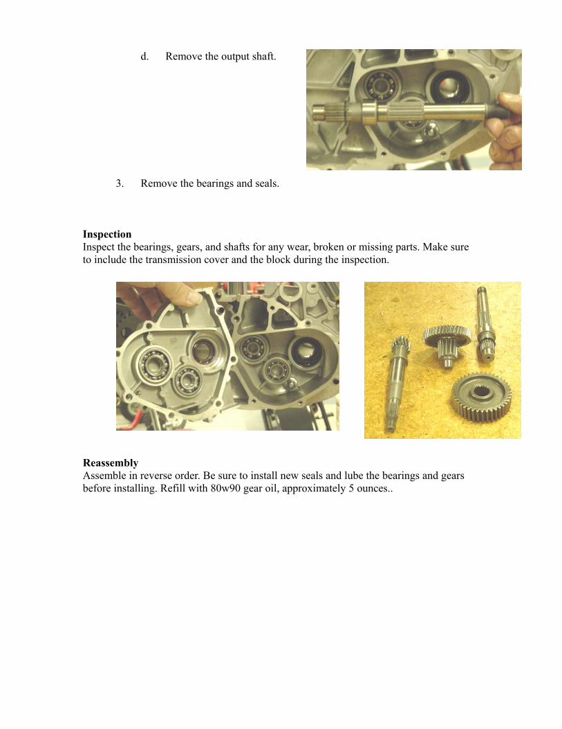
d. Remove the output shaft.
3. Remove the bearings and seals. Inspection Inspect the bearings, gears, and shafts for any wear, broken or missing parts. Make sure to include the transmission cover and the block during the inspection. Reassembly Assemble in reverse order. Be sure to install new seals and lube the bearings and gears before installing. Refill with 80w90 gear oil, approximately 5 ounces..

Chapter 6
Brakes The rear braking system on some models are operated with cables and springs whereas others are hydraulic. The rear hydraulic units will use the same process and procedure as the front brakes. The front brake system is hydraulic. If any of these items should fail, replace parts with new OEM parts. To try and fix a damaged part in this system could cause severe injury to the rider and or bystanders.
Make sure that the bike is securely supported while it is on stands.
When ever any brake work is performed, always go through the
adjustment/bleeding procedure.
Front/Rear Hydraulic Brakes Removal of Caliper
1. Remove the bolts that secure the caliper assembly onto the front shock.
2. Lift the caliper from the rotor.

Inspection Inspect the pads and the rotor for any signs of wear, cracking, or grooves. Replace the parts if needed. If the lining on the pads is less than 0.080” thick, replace the pads. Installation Before installing the pads on the caliper remove the cap on the reservoir and slowly squeeze the piston all the back. Install the pads into the caliper and carefully slid it over the brake rotor. Move the caliper into place and bolt it down. Bleed the brakes.
When installing the pads, the tabs on the end of the pads need to fit into the metal
retainers in the caliper.
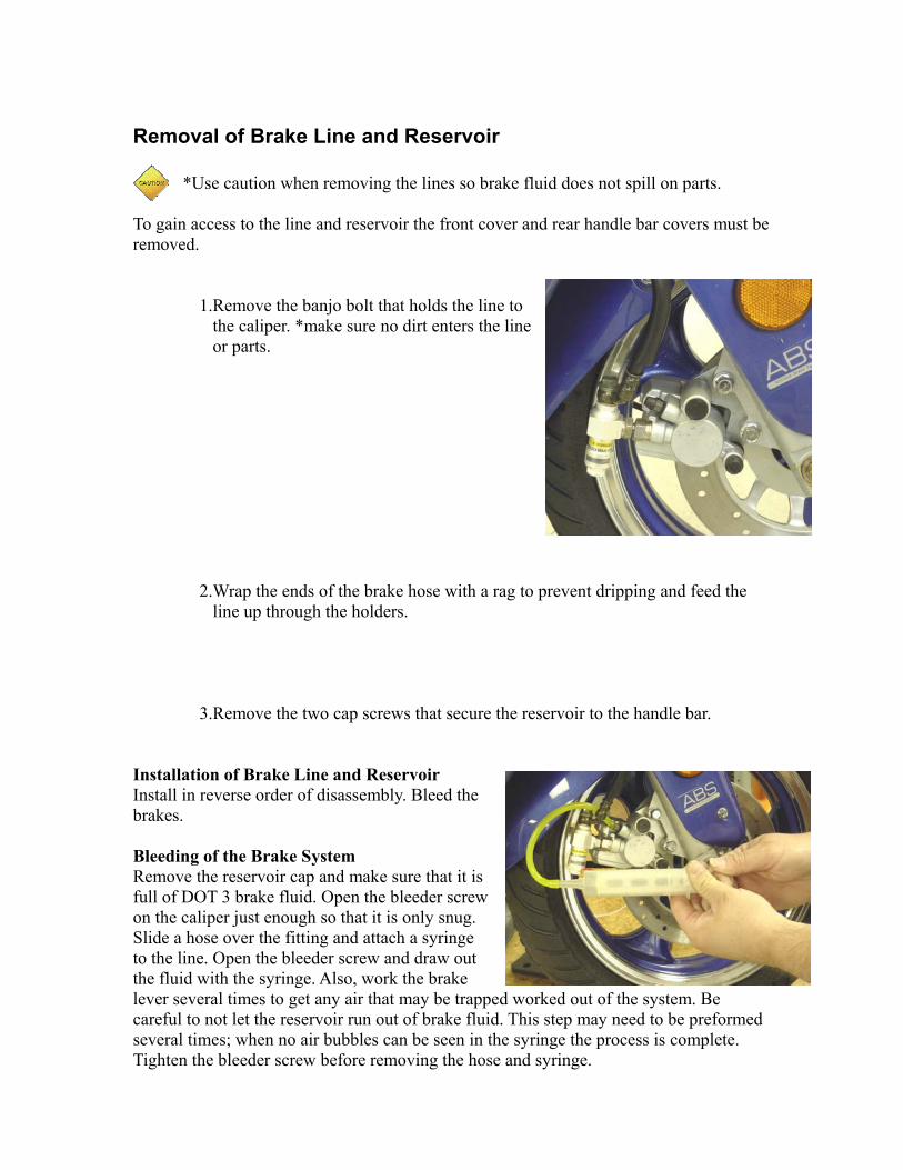
Removal of Brake Line and Reservoir
*Use caution when removing the lines so brake fluid does not spill on parts.
To gain access to the line and reservoir the front cover and rear handle bar covers must be removed.
1.Remove the banjo bolt that holds the line to the caliper. *make sure no dirt enters the line or parts.
2.Wrap the ends of the brake hose with a rag to prevent dripping and feed the line up through the holders.
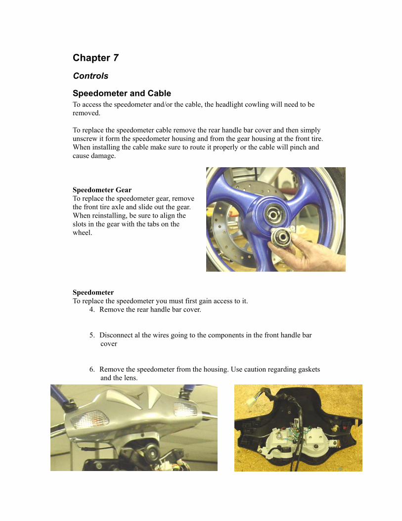
3.Remove the two cap screws that secure the reservoir to the handle bar. Installation of Brake Line and Reservoir Install in reverse order of disassembly. Bleed the brakes. Bleeding of the Brake System Remove the reservoir cap and make sure that it is full of DOT 3 brake fluid. Open the bleeder screw on the caliper just enough so that it is only snug. Slide a hose over the fitting and attach a syringe to the line. Open the bleeder screw and draw out the fluid with the syringe. Also, work the brake lever several times to get any air that may be trapped worked out of the system. Be careful to not let the reservoir run out of brake fluid. This step may need to be preformed several times; when no air bubbles can be seen in the syringe the process is complete. Tighten the bleeder screw before removing the hose and syringe.
Chapter 7
Controls
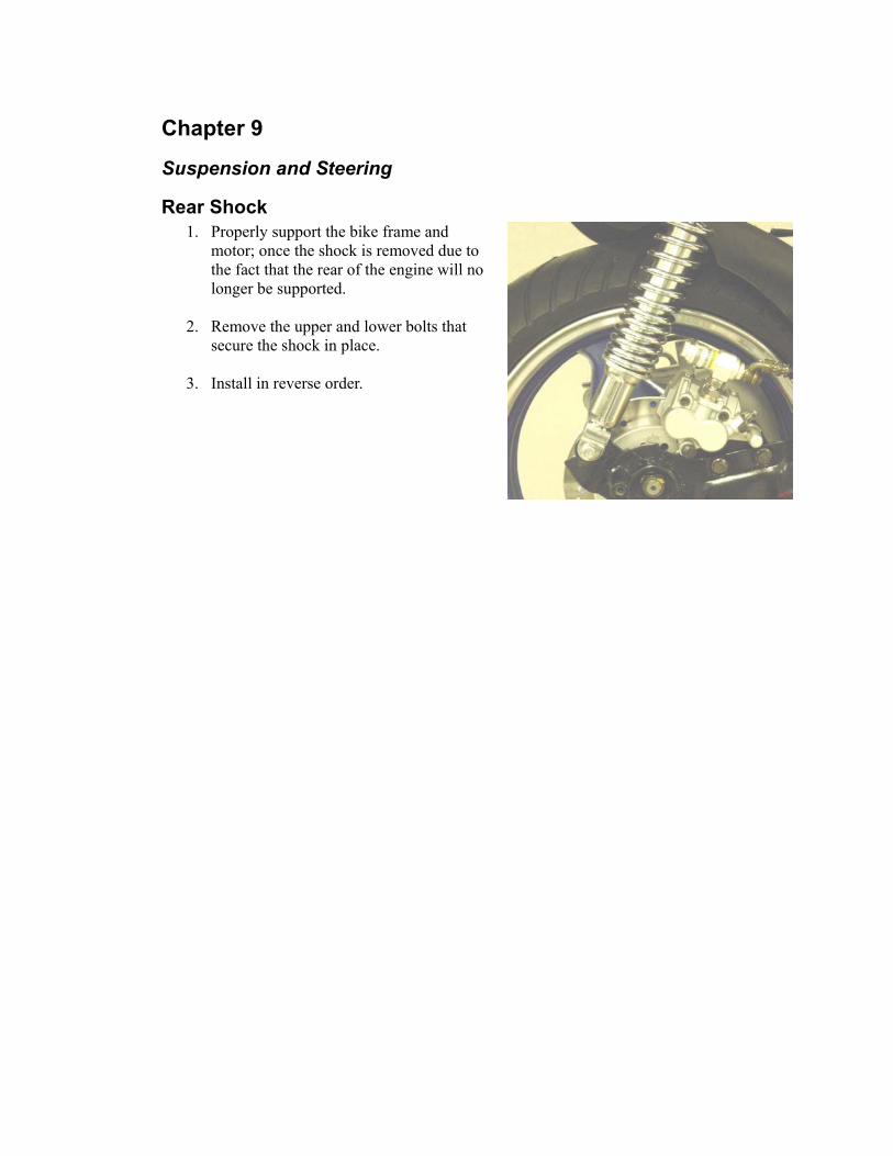
Speedometer and Cable To access the speedometer and/or the cable, the headlight cowling will need to be removed. To replace the speedometer cable remove the rear handle bar cover and then simply unscrew it form the speedometer housing and from the gear housing at the front tire. When installing the cable make sure to route it properly or the cable will pinch and cause damage. Speedometer Gear To replace the speedometer gear, remove the front tire axle and slide out the gear. When reinstalling, be sure to align the slots in the gear with the tabs on the wheel. Speedometer To replace the speedometer you must first gain access to it.
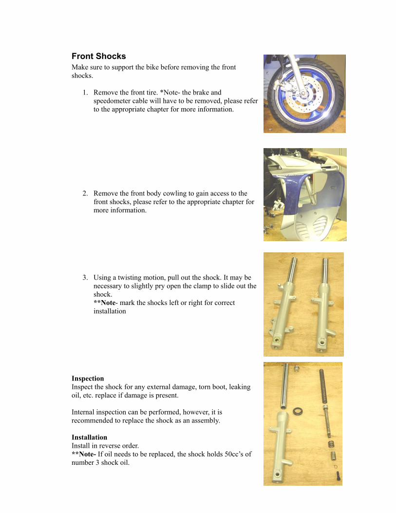
4. Remove the rear handle bar cover. 5. Disconnect al the wires going to the components in the front handle bar
cover 6. Remove the speedometer from the housing. Use caution regarding gaskets
and the lens.

Adjusting the Throttle Cable There are two places to adjust the throttle cable, near the throttle grip and on the carburetor. When adjusting the cable only remove the slack from the cable, do not put it under tension as this starts to open the slide on the carburetor. To adjust the throttle cable free-play: On the carburetor 1. Loosen the jam nut 2. Turn the cable adjustment nut clockwise to increase free-play in the cable. Turn the adjustment nut counterclockwise to decrease free-play in the cable. 3. There should be approximately 3 mm (1/8 in.) free-play in the cable. 4. Tighten the jam nut to secure the adjustment On the handlebar Adjusting the cable on the handle bar is only done when installing a new cable or there is no more adjustment on the carburetor.
1. Disconnect throttle cable at the carburetor. 2. Loosen the jam nut on the throttle cable on
the handlebar. 3. Turn the connector in to lengthen the cable
or out to shorten the cable. 4. Reinstall the cable on the carburetor.
Adjusting Engine RPM (Idle) To properly adjust the idle RPM, a tachometer is necessary. To adjust idle RPM, use the following procedure. Set the brake lever locks. Start the engine and Warm it up to normal operating temperature. 2. Turn the idle adjustment screw in or out until the engine idles at 1700 +\- 100 RPM. *Caution Adjust the idle to the correct RPM. Make sure the engine is at normal operating temperature before adjusting the idle RPM.

Throttle Cable 1. Remove the screw from the throttle grip and slide the grip off the handle bar.
Once the grip is far enough off, remove the cable. 2. Remove the cover from the throttle slide on the carburetor, see chapter 2.
3. Pull cable assembly through the frame. It will be necessary to remove the floor
panel to route and zip tie the cable properly. *Note- Pay attention as to the routing of the cable so it will not get pinched or kinked. Reassemble in the reverse order.
Chapter 9
Suspension and Steering
Rear Shock 1. Properly support the bike frame and
motor; once the shock is removed due to the fact that the rear of the engine will no longer be supported.
2. Remove the upper and lower bolts that
secure the shock in place.
3. Install in reverse order.
Front Shocks Make sure to support the bike before removing the front shocks.
1. Remove the front tire. *Note- the brake and speedometer cable will have to be removed, please refer to the appropriate chapter for more information.
2. Remove the front body cowling to gain access to the front shocks, please refer to the appropriate chapter for more information.
3. Using a twisting motion, pull out the shock. It may be necessary to slightly pry open the clamp to slide out the shock. **Note- mark the shocks left or right for correct installation
Inspection Inspect the shock for any external damage, torn boot, leaking oil, etc. replace if damage is present. Internal inspection can be performed, however, it is recommended to replace the shock as an assembly. Installation Install in reverse order. **Note- If oil needs to be replaced, the shock holds 50cc’s of number 3 shock oil.
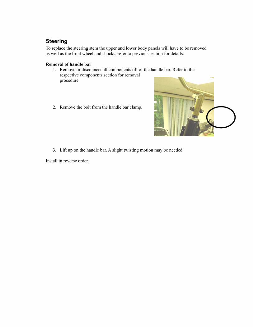
Steering To replace the steering stem the upper and lower body panels will have to be removed as well as the front wheel and shocks, refer to previous section for details. Removal of handle bar
1. Remove or disconnect all components off of the handle bar. Refer to the respective components section for removal procedure.
2. Remove the bolt from the handle bar clamp.
3. Lift up on the handle bar. A slight twisting motion may be needed. Install in reverse order.

Removal of Steering Stem
1. Remove handle bar
2. Remove the spanner nuts.
3. Remove the Washer

4. Remove the upper bearing race.
5. Remove the bearing. Pay attention to the direction of the bearings.
6. Slide out the steering stem. Inspection Inspect the ball bearings and cages for any wear. Check the seats for wear or pitting. Check the stem for any wear. Installation Install in reverse order making sure to grease bearings and stem, make sure that the bearing assemblies are properly seated before tightening the spanner nuts, damage to bearings will result. * Note – when tightening the lower spanner nut, only tighten hand tight until all of the play is gone. Then tighten the upper nut against the lower nut to prevent it from coming undone.