EA3600 Network Connect for Automation...viii EA3600 Network Connect Product Reference Guide Chapter...
88
Industrial Ethernet Adapter Product Reference Guide EA3600 Network Connect for Automation MN-003001-04
Transcript of EA3600 Network Connect for Automation...viii EA3600 Network Connect Product Reference Guide Chapter...
Industrial Ethernet Adapter
Product Reference Guide
EA3600 Network Connect for Automation
MN-003001-04


EA3600 NETWORK CONNECT FOR AUTOMATION
INDUSTRIAL ETHERNET ADAPTERPRODUCT REFERENCE GUIDE
MN-003001-04
Revision A
April 2019

ii EA3600 Network Connect Product Reference Guide
Revision History
Changes to the original guide are listed below:
Change Date Description
-01 Rev. A 5/2017 Initial Release
-02 Rev. A 1/2018 Updates:- Enable Transfer and Select Transfer Mode table, Data Sent to EA3600 column - Removed ’all caps’ from chapter headings; changed Ethernet/IP to EtherNet/IP
-03 Rev. A 8/2018 Updated:- Figure 1-3 - 12V power supply must be purchased separately.
-04 Rev. A 4/2019 Updated:- Table 2-2- Table 2-3- Ethernet IP chapter
Added:- Configuring Using the EA3600 Add On Profile- Config Port to Device Configuration parameter settings.- New section for programming device with barcodes.- New chapter for TCP/IP.

TABLE OF CONTENTS
Revision History ................................................................................................................................. ii
About This GuideIntroduction ....................................................................................................................................... viiConfigurations................................................................................................................................... viiChapter Descriptions ....................................................................................................................... viiiNotational Conventions.................................................................................................................... viiiRelated Documents and Software .................................................................................................... ix
Documentation ............................................................................................................................ ixSoftware ...................................................................................................................................... ix
Service Information ........................................................................................................................... ix
Chapter 1: Initial SetupIntroduction .................................................................................................................................... 1-1Hardware/Software Prerequisites .................................................................................................. 1-1EA3600 Initial Settings and Status ................................................................................................. 1-2
Factory Default Settings ........................................................................................................... 1-2Reset Button ............................................................................................................................ 1-2Status Indications ..................................................................................................................... 1-3Connection Setup ..................................................................................................................... 1-3
Using a 24V DC to Power the EA3600 .............................................................................. 1-4Configuring the EA3600 ........................................................................................................... 1-6
Verifying EA3600 Barcode Scanning Functionality ........................................................................ 1-8Updating EA3600 Firmware ........................................................................................................... 1-8Installing the EA3600 ..................................................................................................................... 1-9
Chapter 2: Ethernet InterfaceIntroduction .................................................................................................................................... 2-1Industrial Protocol Support ............................................................................................................. 2-1Selecting the Active Industrial Ethernet Protocol ........................................................................... 2-1Setting IP Address Configuration ................................................................................................... 2-2Industrial Ethernet Developer Files (ZIP File Contents) ................................................................. 2-2
Device Definition Files .............................................................................................................. 2-2

iv EA3600 Network Connect Product Reference Guide
Sample Application Files .......................................................................................................... 2-3Sample Function Block/Library/Routine Files .......................................................................... 2-3
EA3600 PLC I/O Reference ........................................................................................................... 2-4Barcode Input Data .................................................................................................................. 2-4Barcode Input Data - Status Register ...................................................................................... 2-5Barcode Output Data ............................................................................................................... 2-6Barcode Output Data - Control Register .................................................................................. 2-6
Chapter 3: Barcode TransferIntroduction .................................................................................................................................... 3-1Transfer Modes .............................................................................................................................. 3-1
Basic Mode .............................................................................................................................. 3-1Handshake Mode ..................................................................................................................... 3-1Fragmentation Mode ................................................................................................................ 3-1
Reading Barcode Data from the EA3600 ....................................................................................... 3-2Enabling Barcode Transfer ...................................................................................................... 3-2Selecting Transfer Mode .......................................................................................................... 3-2Basic Mode .............................................................................................................................. 3-2
Transfer Control ................................................................................................................. 3-2Barcode Data ..................................................................................................................... 3-2
Handshake Mode ..................................................................................................................... 3-3Transfer Control ................................................................................................................. 3-3Barcode Data ..................................................................................................................... 3-3Barcode Transfer Error Handling ....................................................................................... 3-3Sequence Chart ................................................................................................................. 3-3
Fragmentation Mode ................................................................................................................ 3-4Transfer Control ................................................................................................................. 3-4Barcode Data Fragmentation Control ................................................................................ 3-4Sequence Chart ................................................................................................................. 3-5
Determining Trigger State .............................................................................................................. 3-5Barcode Type Table ....................................................................................................................... 3-6Sending Alerts/Actions to the Scanner .......................................................................................... 3-9
Chapter 4: PROFINET Interface Introduction .................................................................................................................................... 4-1
Communications Profile ........................................................................................................... 4-1GSDML File .............................................................................................................................. 4-1Identification and Maintenance Functions ................................................................................ 4-1PROFINET IO Modules ............................................................................................................ 4-2
Status and Barcode Data IO Module ................................................................................. 4-2Configuring Siemens S7 Communications .................................................................................... 4-2
Register the GSDML File ......................................................................................................... 4-2Adding the EA3600 to the I/O Configuration ............................................................................ 4-2I/O Data Mapping ..................................................................................................................... 4-6Setting the PROFINET Device Name ...................................................................................... 4-7
Transferring Barcode Data from the EA3600 ................................................................................. 4-8Sample Application for TIA v15.1 ................................................................................................... 4-8
EA3600_TIA_Sample Barcode Transfer Example Logic ......................................................... 4-9Using the Barcode Transfer Logic ...................................................................................... 4-9

Table of Contents v
Chapter 5: EtherNet/IP InterfaceIntroduction .................................................................................................................................... 5-1
Communications Profile ........................................................................................................... 5-1EDS File ................................................................................................................................... 5-1Supported Objects ................................................................................................................... 5-2
TCP/IP Interface Object ..................................................................................................... 5-2Ethernet Link Object ........................................................................................................... 5-2
I/O Assemblies ......................................................................................................................... 5-2Status and Barcode Data Assembly .................................................................................. 5-2Barcode Transfer Control Assembly .................................................................................. 5-2
I/O Connections ....................................................................................................................... 5-3Exclusive Owner Connection ............................................................................................. 5-3
Configuring Rockwell Automation ControlLogix Communication ................................................... 5-3Configuring Using EDS Profile (ControlLogix v. 20 and later) .................................................. 5-3
Register the EA3600 EDS File ........................................................................................... 5-3Add the EA3600 to the I/O Configuration ........................................................................... 5-4EA3600 I/O Tags ................................................................................................................ 5-6
Configuring Using Generic EtherNet/IP Module ....................................................................... 5-7Adding the EA3600 to the I/O Configuration ...................................................................... 5-7EA3600 Tags ..................................................................................................................... 5-9
Configuring Using the EA3600 Add On Profile ...................................................................... 5-10Installing the AOP ............................................................................................................ 5-10Adding the EA3600 to the I/O Configuration .................................................................... 5-13EA3600 I/O Tags .............................................................................................................. 5-15
Transferring Barcode Data from the EA3600 ............................................................................... 5-15Sample Application for Logix Studio 5000 v24 With AOP ............................................................ 5-16
EA3600Sample Barcode Transfer Example Logic ................................................................. 5-16Using the Barcode Transfer Logic .................................................................................... 5-16ScannerRoutine ............................................................................................................... 5-16
Chapter 6: Modbus TCP InterfaceIntroduction .................................................................................................................................... 6-1
Communications Profile ........................................................................................................... 6-1Modbus Unit Identifier .............................................................................................................. 6-1Supported Modbus Functions .................................................................................................. 6-1Modbus Register Mapping ....................................................................................................... 6-2
EA3600 Identity and Version Information Registers .......................................................... 6-2Status and Barcode Data Registers ................................................................................... 6-2Barcode Transfer Control Registers ................................................................................... 6-3
Transferring Barcode Data from the EA3600 ................................................................................. 6-3Example Barcode Transfer Register Commands ..................................................................... 6-3
Enable Transfer and Select Transfer Mode ....................................................................... 6-4Basic Mode Transfers ........................................................................................................ 6-4Handshake Mode Transfers ............................................................................................... 6-4
Chapter 7: TCP/IP InterfaceIntroduction .................................................................................................................................... 7-1Finding Devices ............................................................................................................................. 7-1
Broadcast Send Packet Details From the Host ........................................................................ 7-1

vi EA3600 Network Connect Product Reference Guide
Unicast Receive Packet Details From the Device .................................................................... 7-2Receiving Barcode Data ................................................................................................................ 7-2
Unicast Receive Packet Details From the Device .................................................................... 7-2Zebra TCP/IP Sample Application ................................................................................................. 7-3
Notes About the Other UI Elements ......................................................................................... 7-4
Chapter 8: Programming BarcodesIntroduction .................................................................................................................................... 8-1Programming the EA3600 with Barcodes ...................................................................................... 8-1
EA3600 Parameter Pass-Through ........................................................................................... 8-2Industrial Ethernet Protocol ...................................................................................................... 8-3Transmit Length and Code Type over TCP/IP ......................................................................... 8-4Additional Configuration Settings with Barcodes ..................................................................... 8-4
Appendix A: TroubleshootingTroubleshooting ............................................................................................................................ A-1
Index

ABOUT THIS GUIDE
Introduction
This guide provides information on the use of the Industrial Ethernet interface on the EA3600 Connect for Automation Industrial Ethernet Adapter.
Configurations
This guide includes the EA3600 Network Connection configurations listed in the following table.
NOTE Screens and windows pictured in this guide are samples and can differ from actual screens.
Configuration Description
EA3600-R1CP-00 EtherNet/IP, Modbus TCP, and Standard TCP/IP; Point-To-Point
EA3600-R1CM-00 EtherNet/IP, Modbus TCP, and Standard TCP/IP; Multi-Point
EA3600-S1CP-00 PROFINET, Modbus TCP, and Standard TCP/IP; Point-To-Point
EA3600-S1CM-00 PROFINET, Modbus TCP, and Standard TCP/IP; Multi-Point
EA3600-T1CP-00 Standard TCP/IP - Point-To-Point
Note: Multi-point EA3600 configurations support multiple DS3678 scanners to be connected to a single STB/FLB3678 cradle with limited functionality.

viii EA3600 Network Connect Product Reference Guide
Chapter Descriptions
Topics covered in this guide are as follows:
• Chapter 1, Initial Setup, provides information about how to perform setup and configure the EA3600 adapter.
• Chapter 2, Ethernet Interface, provides an overview of the Industrial Ethernet (IE) interface.
• Chapter 3, Barcode Transfer, provides the details of how this transfer is accomplished, independent of the protocol being used.
• Chapter 4, PROFINET Interface, provides information about PROFINET IO modules including the steps and screen shots to configure the Siemens S7 communications, and transferring barcode data from the EA3600.
• Chapter 5, EtherNet/IP Interface, provides information about I/O assemblies, I/O connections, steps to configure Rockwell Automation ControlLogix communication, and transferring barcode data from the EA3600.
• Chapter 6, Modbus TCP Interface, provides information about using the Modbus TCP interface to transfer barcode data from the EA3600.
• Appendix A, Troubleshooting provides the symptoms and solutions to common issues.
Notational Conventions
The following conventions are used in this document:
• Italics are used to highlight the following:
• Chapters and sections in this guide
• Related documents
• Bold text is used to highlight the following:
• Dialog box, window and screen names
• Drop-down list and list box names
• Check box and radio button names
• Icons on a screen
• Key names on a keypad
• Button names on a screen.
• Bullets (•) indicate:
• Action items
• Lists of alternatives
• Lists of required steps that are not necessarily sequential.
• Sequential lists (e.g., those that describe step-by-step procedures) appear as numbered lists.

About This Guideix
Related Documents and Software
Documentation
• DS36X8 Product Reference Guide (p/n MN-002689-xx) provides general instructions for setting up, operating, maintaining, and troubleshooting the cordless DS3678 and corded DS3608 digital scanners.
• DS3678 Quick Start Guide (p/n MN002648Axx) provides general information for getting started with the DS3678 digital scanner and includes basic set up and operation instructions.
• DS3608 Quick Start Guide, p/n MN002257Axx provides general information for getting started with the DS3608 digital scanner and includes basic set up and operation instructions.
• STB3678 Cradle Quick Reference Guide (p/n MN002334Axx) provides basic instructions on setting up and using the cradle; provides Regulatory and Waste Electrical and Electronic Equipment information.
• FLB3678 Cradle Quick Reference Guide (p/n MN002336Axx) provides basic instructions on setting up and using the cradle; provides Regulatory and Waste Electrical and Electronic Equipment information.
Software
For the latest version of the Zebra Industrial Ethernet Software, and the latest versions of all guides, go to: http://www.zebra.com/support.
Service Information
If you have a problem with your equipment, contact Zebra Global Customer Support for your region. Contact information is available at: http://www.zebra.com/support.
When contacting support, please have the following information available:
• Serial number of the unit
• Model number or product name
• Software type and version number.
Zebra responds to calls by email, telephone or fax within the time limits set forth in support agreements.
If your problem cannot be solved by Zebra Customer Support, you may need to return your equipment for servicing and will be given specific directions. Zebra is not responsible for any damages incurred during shipment if the approved shipping container is not used. Shipping the units improperly can possibly void the warranty.
If you purchased your Zebra business product from a Zebra business partner, contact that business partner for support.

x EA3600 Network Connect Product Reference Guide
Chapter 1 Initial Setup
Introduction
This chapter provides information about how to perform initial setup of the EA3600 adapter. It also includes information on how to use the Zebra Industrial Ethernet Configuration Utility to verify functionality and configure the EA3600. The latest version of this software can be downloaded from the Zebra support website at: http://www.zebra.com/support.
Hardware/Software Prerequisites
The following list of components is required for initial setup, testing, and development of Industrial Ethernet applications that use the EA3600.
• EA3600 Network Connect Adapter
• A compatible Zebra corded or cordless scanner (such as a DS3608 or DS3678).
• For a cordless scanner setup, an appropriate cradle (such as an STB3678 or FLB3678) is also required.
• Zebra Industrial Ethernet Configuration Utility software.
• A PC running Windows 7, or higher, to run the Zebra Industrial Ethernet Configuration Utility.
• An Industrial Ethernet PLC (Programmable Logic Controller) that supports one of the support protocols (EtherNet/IP, PROFINET, or Modbus TCP).
• Ethernet switch or router (if not connecting EA3600 directly to a PLC) and Ethernet cables.
• Industrial Ethernet Developer Files zip file (CAAEAS00-001-RXXD0.ZIP) that includes the following components:
• EDS files and Logix Designer Sample application and exported Scanner Routine.
• GSDML files and Step 7/TIA Sample applications and function blocks.
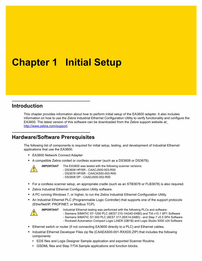
IMPORTANT The EA3600 was tested with the following scanner versions:- DS3608 HP/SR - CAACJS00-003-R00- DS3678 HP/SR - CAACKS00-003-R00- DS3608 DP - CAADJS00-002-R00
IMPORTANT Industrial Ethernet testing was performed with the following PLCs and software:- Siemens SIMATIC S7-1200 PLC (6ES7 215-1AG40-0XB0) and TIA v15.1 SP1 Software- Siemens SIMATIC S7-300 PLC (6ES7 317-2EK14-0AB0) - and Step 7 v5.5 SP4 Software- Rockwell Automation Compact Logix L24ER (QB1B) and Logix Studio 5000 v24 Software

1 - 2 EA3600 Network Connect Product Reference Guide
EA3600 Initial Settings and Status
Factory Default Settings
It is important to note the factory default configuration of the EA3600 described in this section. In the event that the default configuration does not match your desired configuration, either the Zebra Industrial Ethernet Configuration Utility or the appropriate PLC vendor software must be used to modify the configuration.
The factory default configuration of the EA3600 is dependent upon the SKU purchased and is set as follows.
• For Rockwell Automation SKU, EtherNet/IP is the default Active Industrial Ethernet Protocol.
• For Siemens SKU, PROFINET is the default Active Industrial Ethernet Protocol.
• IP Address mode: DHCP (Dynamic Host Control Protocol) with a 30 second timeout.
Reset Button
A Reset button is available on the EA3600 in the event that you would like to restore the EA3600 to its factory defaults. To perform a factory reset, use a paper clip to hold down the Reset button for 10+ seconds. The Device Status LED turns off to indicate that the button was held for a long enough period of time. Upon release of the Reset button the internally saved configuration is cleared and the EA3600 reboots.
Figure 1-1 EA3600 Reset Button
NOTE The EA3600 factory default Ethernet IP address configuration has DHCP enabled, and a 30 second timeout on DHCP. In the event that the DHCP address is not received within the timeout value of 30 seconds, the device falls back to an AutoIP address of 192.168.0.100.
Reset Button
Initial Setup 1 - 3
Status Indications
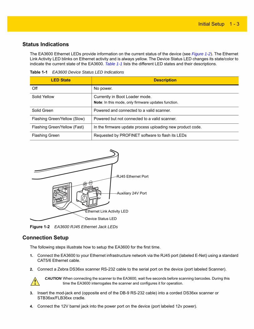
The EA3600 Ethernet LEDs provide information on the current status of the device (see Figure 1-2). The Ethernet Link Activity LED blinks on Ethernet activity and is always yellow. The Device Status LED changes its state/color to indicate the current state of the EA3600. Table 1-1 lists the different LED states and their descriptions.
Figure 1-2 EA3600 RJ45 Ethernet Jack LEDs
Connection Setup
The following steps illustrate how to setup the EA3600 for the first time.
1. Connect the EA3600 to your Ethernet infrastructure network via the RJ45 port (labeled E-Net) using a standard CAT5/6 Ethernet cable.
2. Connect a Zebra DS36xx scanner RS-232 cable to the serial port on the device (port labeled Scanner).
3. Insert the mod-jack end (opposite end of the DB-9 RS-232 cable) into a corded DS36xx scanner or STB36xx/FLB36xx cradle.
4. Connect the 12V barrel jack into the power port on the device (port labeled 12v power).
Table 1-1 EA3600 Device Status LED Indications
LED State Description
Off No power.
Solid Yellow Currently in Boot Loader mode.Note: In this mode, only firmware updates function.
Solid Green Powered and connected to a valid scanner.
Flashing Green/Yellow (Slow) Powered but not connected to a valid scanner.
Flashing Green/Yellow (Fast) In the firmware update process uploading new product code.
Flashing Green Requested by PROFINET software to flash its LEDs
Device Status LED
Ethernet Link Activity LED
RJ45 Ethernet Port
Auxiliary 24V Port
CAUTION When connecting the scanner to the EA3600, wait five seconds before scanning barcodes. During this time the EA3600 interrogates the scanner and configures it for operation.

1 - 4 EA3600 Network Connect Product Reference Guide
Alternatively, connect power and ground wires from an auxiliary 24v source. See Using a 24V DC to Power the EA3600 on page 1-4 for more information.
5. The EA3600 Ethernet Jack LED is green when the EA3600 is powered and a valid scanner is connected. The Ethernet Jack Activity LED is yellow (flashing to show activity) when the EA3600 is connected to a valid Ethernet network.
Figure 1-3 EA3600 Network Connect Setup Overview
Using a 24V DC to Power the EA3600
The EA3600 can be configured to use one of two 2 different power connections (see Figure 1-3).
To set up power for a 24V connection (Figure 1-6):
RS-232 Scanner Cable (CBA-RF2-C09ZAR)
DS3608(corded)
DS3678(cordless)
12V Power Supply(must be purchased separately)
EA3600
OR
To Host
Ethernet Port
Power Supply
Auxiliary 24VSupply

Initial Setup 1 - 5
1. Pull outward on the connector to remove it from the unit.
Figure 1-4 Removing the Terminal Block From the EA3600
2. Two small flat head screws are exposed when the terminal block is completely removed. Loosen these two screws and properly insert the stripped flying leads from the 24V source into the connector. Pay special attention to the polarity of the wires as shown on the unit. Tighten down the small flat head screws to clamp down the wires.
Figure 1-5 Connecting the 24V Leads
Loosen Two Flat Head Screws
Insert Stripped 24V Flying Leads

1 - 6 EA3600 Network Connect Product Reference Guide
3. Insert the terminal block back into the unit and re-tighten the larger flat head screws to secure the assembly to the unit.
Figure 1-6 Insert Terminal Block and Tighten Screws
Configuring the EA3600
The EA3600 supports both Dynamic Host Control Protocol (DHCP) and Static IP addressing. It is recommended that a network with a DHCP server be used for initial configuration of the EA3600. By default, the EA3600 has DHCP enabled and attempts to obtain an IP address from the DHCP server.
Once an IP address is obtained, use the Zebra Industrial Ethernet Configuration Utility to connect to the EA3600 and follow the steps below to change its configuration.
1. From a Windows 7 (or higher) PC on the same Ethernet network as the EA3600, run the Zebra Industrial Ethernet Configuration Utility by clicking on its shortcut under C:\Program Files (x86)\Zebra Technologies\Industrial Ethernet Software.
2. Click Connect/Disconnect to list the current EA3600 devices located on the network.
a. To find EA3600 devices, a special broadcast packet is sent out. Any EA3600 devices that receive this broadcast packet respond with their IP and MAC information.
b. If no devices are listed, then the EA3600 may not have a valid IP address. Ensure your DHCP server is available and cycle power on your EA3600, then click the Refresh button.
Figure 1-7 Configuration Utility - Connect/Disconnect Dialog
NOTE If no DHCP server is present and EA3600 is configured to use DHCP, a fall back address of 192.168.0.100 is used after a default 30 second timeout period.
NOTE It is expected that the network contains a DHCP server so that the EA3600 can obtain an initial IP address for configuration.
The utility requires the .NET framework version 2.0.
Initial Setup 1 - 7
c. If the connection fails, or IP addresses do not populate in the Connect/Disconnect dialog (even after Refresh is selected) see Appendix A, Troubleshooting.
3. Within the Connect/Disconnect dialog, select the device that matches the MAC address of the EA3600 to which you would like to connect and then click Connect.
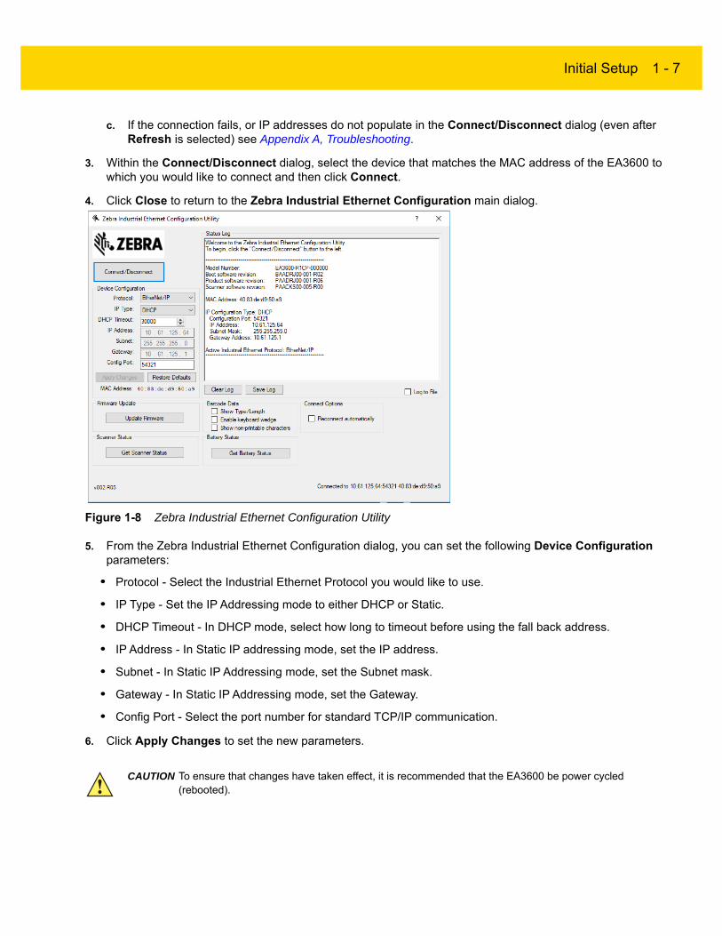
4. Click Close to return to the Zebra Industrial Ethernet Configuration main dialog.
Figure 1-8 Zebra Industrial Ethernet Configuration Utility
5. From the Zebra Industrial Ethernet Configuration dialog, you can set the following Device Configuration parameters:
• Protocol - Select the Industrial Ethernet Protocol you would like to use.
• IP Type - Set the IP Addressing mode to either DHCP or Static.
• DHCP Timeout - In DHCP mode, select how long to timeout before using the fall back address.
• IP Address - In Static IP addressing mode, set the IP address.
• Subnet - In Static IP Addressing mode, set the Subnet mask.
• Gateway - In Static IP Addressing mode, set the Gateway.
• Config Port - Select the port number for standard TCP/IP communication.
6. Click Apply Changes to set the new parameters.
CAUTION To ensure that changes have taken effect, it is recommended that the EA3600 be power cycled (rebooted).

1 - 8 EA3600 Network Connect Product Reference Guide
Verifying EA3600 Barcode Scanning Functionality
The Zebra Industrial Ethernet Utility Status Log can be used to view scanned barcodes from the connected EA3600/DS36xx scanner setup. This is an excellent way to verify that the system is working as expected. The fields shown in Table 1-2 were added to the utility for this purpose.
Updating EA3600 Firmware
Firmware updates for the EA3600 may be available on the Zebra Support website.
To update the firmware:
1. Download the firmware version to the PC running the Zebra Industrial Ethernet Configuration Utility.
2. Connect the PC to the EA3600.
3. Run the Utility and select Connect/Disconnect.
4. From the Connect/Disconnect dialog select Connect.
5. Select Close.
6. Select the Update Firmware button and browse to open the *.hex file (firmware update file).
Table 1-2 Zebra Industrial Ethernet Utility Options
Field Description
Barcode Data
Show Type/Len When checked, the barcode type and the length of the barcode display before the barcode data in the status log.
Enable Keyboard Wedge When checked, sends the scanned data to the top most window on the host PC. This allows scanned decode data to be sent to external applications in the foreground (such as Excel).
Show Non-printable Characters When checked, non-printable characters are converted to human readable form before being displayed.
Connect Options
Reconnect Automatically When checked, the utility attempts to reconnect to the target EA3600 in the event that connection is lost.
IMPORTANT The download process may take up to 1 minute. Do not disconnect the EA3600 or remove power during the update process.

Initial Setup 1 - 9
Installing the EA3600
The EA3600 can be attached to a DIN rail or mounted on a flat surface.
To attach the EA3600 to a DIN rail, secure the clips on the sides of the EA3600 to each edge of the DIN rail by pivoting on the bottom edge to snap into place as shown in Figure 1-9.
Figure 1-9 Attaching the Clips on the EA3600 to a DIN Rail
To remove the EA3600 from a DIN rail, use your finger to lightly lift the top of the clip and disengage. Lift the bottom of the clip off the rail.
Figure 1-10 Removing the Clips From a DIN Rail
DIN Rail

1 - 10 EA3600 Network Connect Product Reference Guide
To install the EA3600 on a flat surface:
1. Unscrew the screws in the clips on either side of the EA3600. Remove the clips.
Figure 1-11 Unscrew the DIN Rail Clips
2. Find a mounting location, turn the EA3600 upside down so that the keyhole is in the mounting position, and mark the surface as shown in Figure 1-12.
Figure 1-12 Keyhole Mounting Position
3. Drive the mounting screws into the marks.
Surface Mount Mark

Chapter 2 Ethernet Interface
Introduction
This chapter provides an overview of the Industrial Ethernet (IE) interface.
Industrial Protocol Support
The EA3600 Industrial Ethernet interface supports the following standard protocols:
• PROFINET (for details, see Chapter 4, PROFINET Interface)
• EtherNet/IP (for details, see Chapter 5, EtherNet/IP Interface)
• Modbus TCP (for details, see Chapter 6, Modbus TCP Interface).
Selecting the Active Industrial Ethernet Protocol
The EA3600 supports one Industrial Ethernet protocol at a time. The active protocol is selected with the Industrial Ethernet Configuration Utility, and any selection change takes effect after the EA3600 is power cycled.
For more information about how to configure the Active IE protocol see Chapter 1, Initial Setup.

2 - 2 EA3600 Network Connect Product Reference Guide
Setting IP Address Configuration
In order to communicate with the EA3600 over Ethernet, the IP address must be set to a valid address on the same subnet as the computer, or controller used for communication. This may be done using DHCP, or the address may be configured statically.
PROFINET does not require the EA3600 to have an IP address configuration to start communication on the network; the controller may be configured to set the IP address of the devices based on the PROFINET name. The IP configuration need not be set if the active protocol is PROFINET. However, if another protocol is selected, or if non-industrial tools are to be used for functions like firmware updates or other non-I/O functions, the EA3600 must have an IP address configured for these purposes.
The IP address configuration used by the Ethernet interface may be set with the Zebra Industrial Ethernet Configuration Utility. Any change to the configuration takes effect immediately, however, a manual reconnect is necessary when changing IP address configuration.
See Chapter 1, Initial Setup for configuration procedures.
Industrial Ethernet Developer Files (ZIP File Contents)
The Industrial Ethernet Developer Files for the EA3600 are located in a separate ZIP file (CAAEAS00-001-RXXD0.ZIP). This file includes device definition files, sample applications, and ladder logic routines/function blocks to help speed development. This section describes the contents of the zip.
Device Definition Files
To include EA3600 as an IO Module within Rockwell Automation Logix Designer or Siemens Step7 a Device Definition file needs to be installed. Table 2-1 lists the files.
For detailed information about how to install these device definition files see the appropriate chapter for your Industrial Protocol.
Table 2-1 Definition File Listing
Industrial Protocol (Development Environment) Device Definition File Image File Folder
Location
EtherNet/IP (Logix 5000 Studio) Zebra_EA3600.eds Zebra_EA3600.ico EtherNetIP\
PROFINET (Totally Integrated Automation/Step 7)
GSDML-V2.33 -Zebra-EA3600-2-20181115.xml
GSDML-034B-0002-EA3600.bmp PROFINET\

Ethernet Interface 2 - 3
Sample Application Files
To aid in initial application development, sample applications are provided. These sample applications include the use of the Scanner Function Blocks and/or Scanner Routines that are also provided as separate exported components. Three sample applications are provided and are located in the folders that match their respective protocols and development environment.
• EthernetIP\Logix_v24\EA3600Sample.zip
This sample must be unzipped before it is loaded. The sample application was built using RS Logix Designer Studio 5000 v24. It uses ScannerRoutine which abstracts much of the EA3600 logic necessary to work with scanning.
• Profinet\TIAv15.1\EA3600_TIA_Sample_v15.1.zap15_1
This archived sample application was built using Totally Integrated Automation (TIA) v15.1 SP2. To load this sample application, use the Retrieve feature from TIA v15.1 or higher File menu. It uses the EA3600 Library which abstracts much of the EA3600 logic necessary to work with scanning.
Sample Function Block/Library/Routine Files
In a further effort to aid application developers who use alternate versions of Rockwell Automation and Siemens development environments, an exported Function Block, Library, and Routine are provided. These components are listed below along with notes on how to load them into projects.
• EthernetIP\Logix_v24\ScannerRoutine.L5X
From within RS Logix Designer Studio 5000, select Import Component\Routine from the File menu to load this routine.
• Profinet\TIAv15.1\EA3600Lib.zal15_1
From within TIA v15.1, open this Global library and drag and drop its components into your current project.
NOTE These files must be installed into the appropriate development environment for the sample applications to work correctly.
2 - 4 EA3600 Network Connect Product Reference Guide
EA3600 PLC I/O Reference
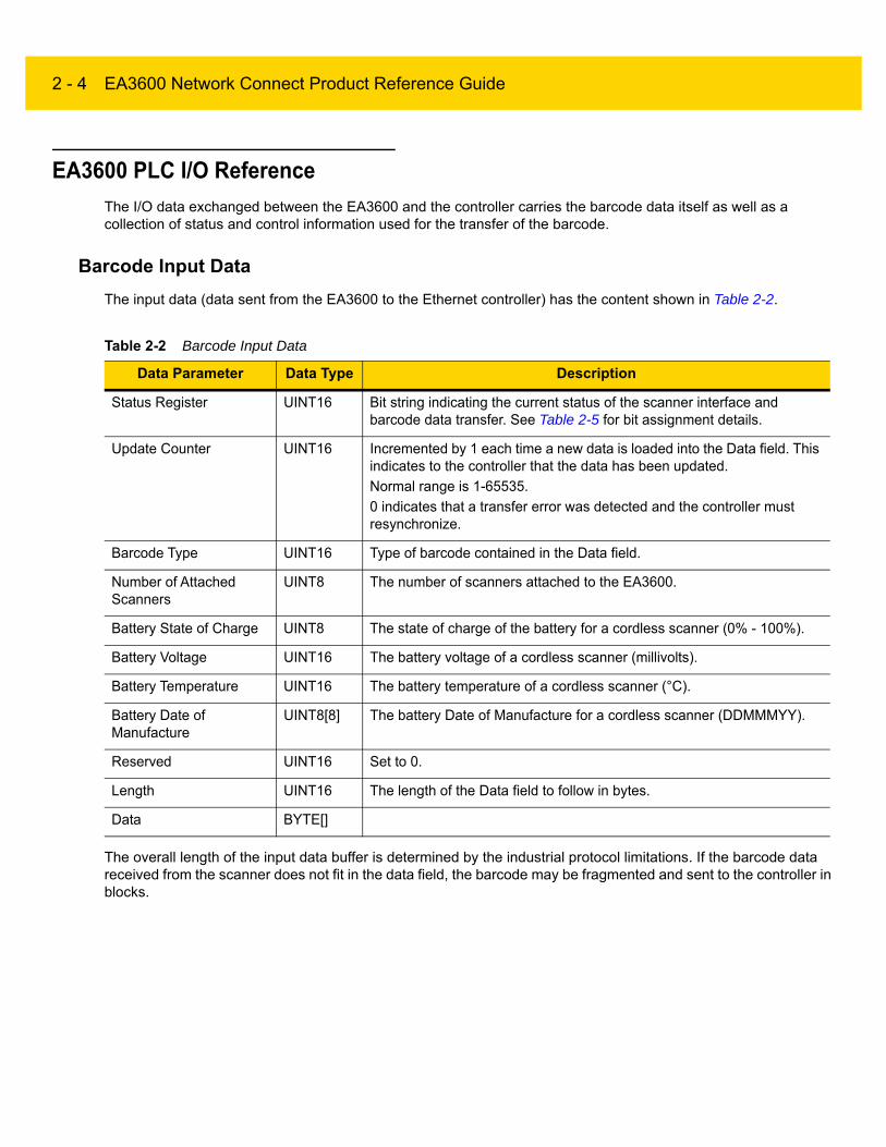
The I/O data exchanged between the EA3600 and the controller carries the barcode data itself as well as a collection of status and control information used for the transfer of the barcode.
Barcode Input Data
The input data (data sent from the EA3600 to the Ethernet controller) has the content shown in Table 2-2.
The overall length of the input data buffer is determined by the industrial protocol limitations. If the barcode data received from the scanner does not fit in the data field, the barcode may be fragmented and sent to the controller in blocks.
Table 2-2 Barcode Input Data
Data Parameter Data Type Description
Status Register UINT16 Bit string indicating the current status of the scanner interface and barcode data transfer. See Table 2-5 for bit assignment details.
Update Counter UINT16 Incremented by 1 each time a new data is loaded into the Data field. This indicates to the controller that the data has been updated.
Normal range is 1-65535.
0 indicates that a transfer error was detected and the controller must resynchronize.
Barcode Type UINT16 Type of barcode contained in the Data field.
Number of Attached Scanners
UINT8 The number of scanners attached to the EA3600.
Battery State of Charge UINT8 The state of charge of the battery for a cordless scanner (0% - 100%).
Battery Voltage UINT16 The battery voltage of a cordless scanner (millivolts).
Battery Temperature UINT16 The battery temperature of a cordless scanner (°C).
Battery Date of Manufacture
UINT8[8] The battery Date of Manufacture for a cordless scanner (DDMMMYY).
Reserved UINT16 Set to 0.
Length UINT16 The length of the Data field to follow in bytes.
Data BYTE[]

Ethernet Interface 2 - 5
Barcode Input Data - Status Register
The Status Register field in the input data is a 16-bit bit string with the bit assignments shown in Table 2-3.
Table 2-3 Status Register Bit Assignments
Bit Name Description
0 Barcode Transfer Status of Barcode Transfer bit.
1 Handshake Mode Status of Handshake Mode bit.
2 Fragmentation Mode Status of Barcode Fragmentation Mode bit.
3 Barcode Cache Overflow
Set when the Barcode Cache is full and a new barcode is received from the scanner. This bit indicates that one or more barcodes have been lost.
This bit is cleared by setting the Clear Faults bit in the Output Control Register.
4 Input Data Overflow Set if Fragmentation Mode is not enabled and the current barcode data does not fit in the Data field of the Input Data buffer. The current barcode has been truncated to fit in the Data field.
This bit is not used if Fragmentation Mode is enabled.
5 Waiting for Handshake Internal state indicating that the scanner is waiting for the update/ACK
Counter handshake.
Set when the scanner is waiting for the ACK Counter to be updated by the controller for the current barcode.
Cleared when the ACK Counter has been set to match the Update Counter.
This bit is not used when Handshake Mode is disabled.
6 Trigger State Set when the trigger button on the scanner is physically pressed. Cleared when the trigger button is released.
This bit is not used if using multi-point EA3600 SKU; it is only activated when using point-to-point EA3600 SKUs.
7 Scanner Type 0=Corded Scanner 1=Cordless Scanner
8 Barcode Fragmented Set if the current barcode data is larger than the Data field and is being sent in blocks.
Cleared if the current barcode data fits in the Data field.
This bit is not used if Fragmentation Mode is disabled.
9 First Fragment Set on the first block of a fragmented barcode transfer.
This bit is not used if Fragmentation Mode is disabled.
10 Middle Fragment Set on all blocks of a fragmented barcode transfer except the first and last.
This bit is not used if Fragmentation Mode is disabled.
11 Last Fragment Set on the last block of a fragmented barcode transfer.
This bit is not used if Fragmentation Mode is disabled.
12-15 Reserved

2 - 6 EA3600 Network Connect Product Reference Guide
Barcode Output Data
The output data (data sent to the EA3600 from the Ethernet controller) has the content shown in Table 2-4.
Barcode Output Data - Control Register
The Control Register field in the output data is a 16-bit bit string with the bit assignments shown in Table 2-5.
Table 2-4 Barcode Output Data
Data Parameter Data Type Description
Control Register UINT16 Bit string used for barcode transfer control. See the bit assignment in the next table.
ACK Counter UINT16 Set to the value of the Input data Update Counter to indicate that the controller has read the Data from the input data.
Normal range is 1-65535.
0 indicates that a transfer error has been detected and the EA3600 must resynchronize.
This field is ignored by the EA3600 if Handshake Mode is disabled.
UI Action Code UINT16 Scanner user indication code (beeps, LEDs flashes, haptics, etc).
Load with UIF code to be sent to the scanner.
This code is sent to the scanner after the 0 to 1 transition of the SendUIAction bit in the Control Register. The SendUIAction should stay 1 for at least one requested packet interval (varies from 8ms to 100ms depending on protocol and PLC).
This bit only works with point-to-point EA3600 SKUs.
Table 2-5 Control Register Bit Assignments
Bit Name Description
0 Barcode Transfer Set to enable Barcode Transfer.
If cleared, scanned barcode data decode data will not be transferred to the PLC.
1 Handshake Mode Set to enable Handshake Mode.
The status of this bit is only read on the rising edge of the Barcode Transfer bit and when held for at least one requested packet interval (varies from 8ms to 100ms depending on protocol and PLC); any changes made otherwise are ignored (i.e., the Handshake Mode is set when the Barcode Transfer is enabled).
2 Fragmentation Mode Set to enable Barcode Fragmentation Mode.
The status of this bit is only read on the rising edge of the Barcode Transfer bit and when held for at least one requested packet interval (varies from 8ms to 100ms depending on protocol and PLC); any changes made otherwise are ignored (i.e., the Fragmentation Mode is set when the Barcode Transfer is enabled).
This bit is ignored if Handshake Mode is not set.
Ethernet Interface 2 - 7
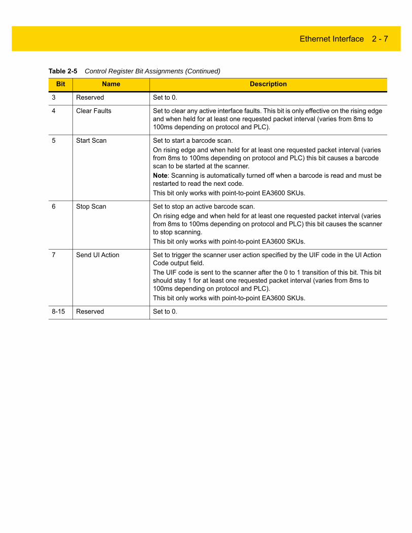
3 Reserved Set to 0.
4 Clear Faults Set to clear any active interface faults. This bit is only effective on the rising edge and when held for at least one requested packet interval (varies from 8ms to 100ms depending on protocol and PLC).
5 Start Scan Set to start a barcode scan.
On rising edge and when held for at least one requested packet interval (varies from 8ms to 100ms depending on protocol and PLC) this bit causes a barcode scan to be started at the scanner.
Note: Scanning is automatically turned off when a barcode is read and must be restarted to read the next code.
This bit only works with point-to-point EA3600 SKUs.
6 Stop Scan Set to stop an active barcode scan.
On rising edge and when held for at least one requested packet interval (varies from 8ms to 100ms depending on protocol and PLC) this bit causes the scanner to stop scanning.
This bit only works with point-to-point EA3600 SKUs.
7 Send UI Action Set to trigger the scanner user action specified by the UIF code in the UI Action Code output field.
The UIF code is sent to the scanner after the 0 to 1 transition of this bit. This bit should stay 1 for at least one requested packet interval (varies from 8ms to 100ms depending on protocol and PLC).
This bit only works with point-to-point EA3600 SKUs.
8-15 Reserved Set to 0.
Table 2-5 Control Register Bit Assignments (Continued)
Bit Name Description

2 - 8 EA3600 Network Connect Product Reference Guide

Chapter 3 Barcode Transfer
Introduction
The transfer of barcode data from the EA3600 to the controller is performed using the same mechanism for all Industrial Ethernet protocols.
This chapter provides the details of how this transfer is accomplished, independent of the protocol being used.
Transfer Modes
The EA3600 provides three modes of barcode transfer mechanisms. The three modes provide increasing level of data integrity and data size capabilities.
Basic Mode
When using Basic Mode transfer, the barcode data is sent to the controller as it is received. There are no checks to verify that the controller read or processed the data; new data overwrites previous data when it is received by the EA3600 from the scanner. Basic Mode is the simplest transfer to implement as it does not require logic in the controller to interact with the EA3600.
Handshake Mode
Handshake Mode adds a level of data integrity to the barcode transfer as the controller must acknowledge each piece of barcode data. The EA3600 does not send new data until the controller indicates that it completed processing the previous data. Barcode scanning is disabled while the controller is busy to guarantee that integrity of the data being processed.
Fragmentation Mode
Some of the Industrial Ethernet protocols have limited message buffer sizes. Fragmentation Mode allows barcode data that is larger than the protocol message buffer to be transferred to the controller. When using Fragmentation Mode if a barcode is larger than the message buffer it is broken up and sent to the controller in multiple blocks and the controller re-assembles the blocks to create the complete barcode.
Fragmentation Mode requires the use of Handshake Mode to guarantee that each fragment block is received by the controller.

3 - 2 EA3600 Network Connect Product Reference Guide
Reading Barcode Data from the EA3600
Enabling Barcode Transfer
Barcode data transfer from the EA3600 to the controller must be enabled by the controller. Transfer is enabled by setting the Barcode Transfer bit in the Control Register.
Transfer may be stopped by clearing the Barcode Transfer bit. If transfer is disabled while a barcode transfer is in progress, that barcode is cached and resent when transfer is enabled.
The barcode mode (Basic, Handshake, Fragmentation) is set on the rising edge of the barcode transfer bit.
Selecting Transfer Mode
The type of transfer mode to be used (Basic, Handshake, Fragmentation) is selected by the controller using the Handshake Mode and Fragmentation Mode bits in the Control Register. These bit are only read by the EA3600 on the rising edge of the Barcode Transfer bit; hence, transfer mode is only set when barcode transfer is enabled.
Table 3-1 describes the transfer mode selection with the Handshake Mode and Fragmentation Mode bits.
Handshake Mode is required for Fragmentation Mode. If Handshake Mode is not set when Fragmentation Mode is set, the combination is invalid and the transfer mode defaults to Basic.
Basic Mode
Transfer Control
In Basic Mode barcode data is loaded into the Input Data buffer as it is read by the EA3600.
When new data is loaded into the Input Data field, the Update Counter is incremented by one to indicate new data is available. Basic Mode provides no acknowledgment mechanism from the controller to indicate that it has completed processing of the data. There is no guarantee that barcode data in the Input Data buffer will not be overwritten before it is processed by the controller.
Barcode Data
In Basic Mode each barcode is sent in a single block in the Input Data field to the controller.
If the barcode data is larger than the size of the Input Data field it is truncated to the available size and the Input Data Overflow bit is set in the Status Register to indicate that the barcode data is truncated.
Table 3-1 Transfer Mode Selection with Handshake Mode and Fragmentation Mode Bits
Handshake Mode Fragmentation Mode Resulting Transfer Mode
OFF OFF Basic
ON OFF Handshake
ON ON Handshake with Fragmentation
OFF ON Invalid

Barcode Transfer 3 - 3
Handshake Mode
Transfer Control
Handshake Mode provides an acknowledgment mechanism that allows the controller to acknowledge that the barcode data in the input buffer has been read. This alleviates the possibility of the EA3600 overwriting the input data before it has been read by the controller.
When new data is loaded into the Input Data field, the Update Counter is incremented by one to indicate new data is available. The Input Data field is not overwritten by the EA3600 until the ACK Counter in the Output data is set to match the Update Counter. The controller uses the change in the Update Counter to determine that data is available, and updates the ACK Counter once it has completed processing the data.
The Update Counter increments consecutively in the range of 1-65535. Zero (0) is a special value and is used to indicate that there is an issue with the barcode transfer.
Barcode Data
In Handshake Mode (non-fragmented) each barcode is sent in a single block in the Input Data field to the controller.
If the barcode data is larger than the size of the Input Data field it is truncated to the available size and the Input Data Overflow bit is set in the Status Register to indicate that the barcode data is truncated.
Barcode Transfer Error Handling
If the EA3600 detects an error in the barcode transfer (the connection was reset, transfer was disabled, etc.), the Update Counter is set to zero (0) and any barcode transfer that is in progress stops.
When the controller detects an error in the barcode transfer it should set the ACK Counter to zero (0). When the EA3600 detects that the ACK Counter was set to zero (0) then any barcode transfer in progress is stopped and the Update Counter sets to zero (0).
Once the EA3600 sets the Update Counter to zero (0), it waits for the ACK Counter to be set to zero (0) by the controller before proceeding. Once both counters are zero (0), any pending barcode transfer is restarted.
Sequence Chart
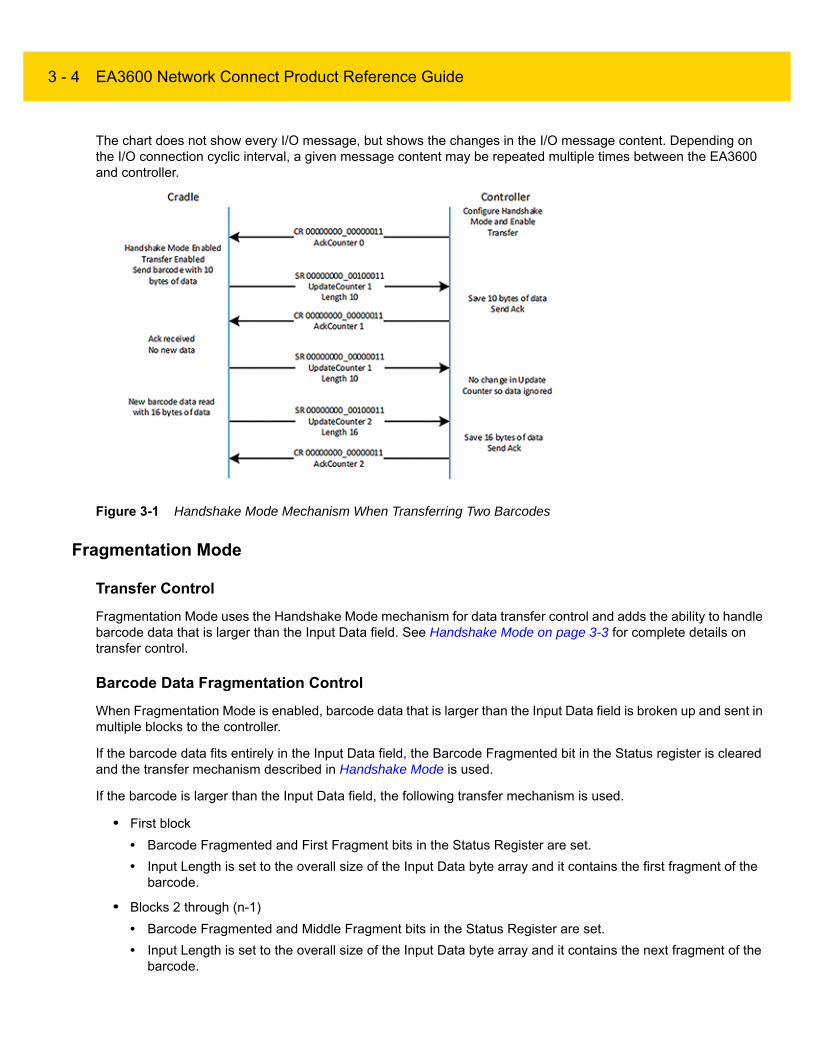
Figure 3-1 illustrates the Handshake Mode mechanism when transferring two barcodes.
3 - 4 EA3600 Network Connect Product Reference Guide
The chart does not show every I/O message, but shows the changes in the I/O message content. Depending on the I/O connection cyclic interval, a given message content may be repeated multiple times between the EA3600 and controller.
Figure 3-1 Handshake Mode Mechanism When Transferring Two Barcodes
Fragmentation Mode
Transfer Control
Fragmentation Mode uses the Handshake Mode mechanism for data transfer control and adds the ability to handle barcode data that is larger than the Input Data field. See Handshake Mode on page 3-3 for complete details on transfer control.
Barcode Data Fragmentation Control
When Fragmentation Mode is enabled, barcode data that is larger than the Input Data field is broken up and sent in multiple blocks to the controller.
If the barcode data fits entirely in the Input Data field, the Barcode Fragmented bit in the Status register is cleared and the transfer mechanism described in Handshake Mode is used.
If the barcode is larger than the Input Data field, the following transfer mechanism is used.
• First block
• Barcode Fragmented and First Fragment bits in the Status Register are set.
• Input Length is set to the overall size of the Input Data byte array and it contains the first fragment of the barcode.
• Blocks 2 through (n-1)
• Barcode Fragmented and Middle Fragment bits in the Status Register are set.
• Input Length is set to the overall size of the Input Data byte array and it contains the next fragment of the barcode.

Barcode Transfer 3 - 5
• Final block
• Barcode Fragmented and Last Fragment bits in the Status Register are set.
• Input Length is set to remaining size of the barcode data.
• The Input Data field contains final portion of the barcode data.
Sequence Chart
Figure 3-2 illustrates the mechanism used to transfer a 1000 byte barcode when the Input Data field size is limited to 400 bytes.
The chart does not show every I/O message, but shows the changes in the I/O message content. Depending on the I/O connection cyclic interval, a given message content may be repeated multiple times between the cradle and controller.
Figure 3-2 Mechanism Transfer 1000 Byte Barcode When Input Data Field Size is Limited to 400 Bytes
Determining Trigger State
The current state of the scanner trigger button can be obtained through the Trigger State status bit. This bit is unset when the trigger is released and set when the trigger is pulled. This feature is only supported with EA3600 Point-To-Point SKUs.
NOTE The Trigger State bit is cleared when a barcode was read by the scanner regardless of the actually trigger button state. This is done to alleviate any confusion that the scanner may still be armed and trying to read a barcode.

3 - 6 EA3600 Network Connect Product Reference Guide
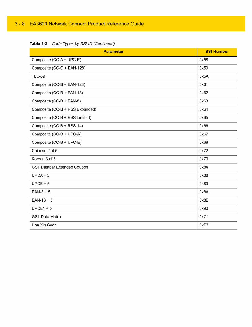
Barcode Type Table
The type of barcode is identified by the 16 bit barcode type SSI ID input data entry.
NOTE Not all Symbologies are supported by the EA3600. Imaging/video and signature capture are not supported.
Table 3-2 Code Types by SSI ID
Parameter SSI Number
Code 39 0x01
Codabar 0x02
Code 128 0x03
Discrete 2 of 5 (DTF) 0x04
IATA 0x05
Interleaved 2 of 5 (ITF) 0x06
Code 93 0x07
UPC-A 0x08
UPC-E 0x09
EAN-8 0x0A
EAN-13 0x0B
Code 11 0x0C
MSI 0x0E
EAN-128 0x0F
UPC-E1 0x10
PDF-417 0x11
Code 39 Full ASCII Conversion 0x13
Trioptic Code 39 0x15
Bookland EAN 0x16
UCC Coupon Extended Code 0x17
ISBT-128 0x19
MicroPDF417 0x1A
Data Matrix 0x1B
QR Code 0x1C
US Postnet 0x1E

Barcode Transfer 3 - 7
US Planet 0x1F
Code 32 0x20
ISBT-128 Concatenation 0x21
Japan Postal 0x22
Australia Post 0x23
Netherlands KIX Code 0x24
Maxicode 0x25
UK Postal 0x27
Macro PDF-417 0x28
Micro QR 0x2C
Aztec 0x2D
GS1 DataBar Omnidirectional (formerly GS1 DataBar-14) 0x30
GS1 DataBar Limited 0x31
GS1 DataBar Expanded 0x32
USPS 4CB/One Code/Intelligent Mail 0x34
UPU FICS Postal 0x35
ISSN EAN 0x36
Matrix 2 of 5 0x39
UPCA + 2 0x48
UPCE + 2 0x49
EAN-8 + 2 0x4A
EAN-13 + 2 0x4B
UPCE1 + 2 0x50
Composite (CC-A + EAN-128) 0x51
Composite (CC-A + EAN-13) 0x52
Composite (CC-A + EAN-8) 0x53
Composite (CC-A + RSS Expanded) 0x54
Composite (CC-A + RSS Limited) 0x55
Composite (CC-A + RSS-14) 0x56
Composite (CC-A + UPC-A) 0x57
Table 3-2 Code Types by SSI ID (Continued)
Parameter SSI Number
3 - 8 EA3600 Network Connect Product Reference Guide
Composite (CC-A + UPC-E) 0x58
Composite (CC-C + EAN-128) 0x59
TLC-39 0x5A
Composite (CC-B + EAN-128) 0x61
Composite (CC-B + EAN-13) 0x62
Composite (CC-B + EAN-8) 0x63
Composite (CC-B + RSS Expanded) 0x64
Composite (CC-B + RSS Limited) 0x65
Composite (CC-B + RSS-14) 0x66
Composite (CC-B + UPC-A) 0x67
Composite (CC-B + UPC-E) 0x68
Chinese 2 of 5 0x72
Korean 3 of 5 0x73
GS1 Databar Extended Coupon 0x84
UPCA + 5 0x88
UPCE + 5 0x89
EAN-8 + 5 0x8A
EAN-13 + 5 0x8B
UPCE1 + 5 0x90
GS1 Data Matrix 0xC1
Han Xin Code 0xB7
Table 3-2 Code Types by SSI ID (Continued)
Parameter SSI Number

Barcode Transfer 3 - 9
Sending Alerts/Actions to the Scanner
In the event that it is required to send a notification to the end user of the scanner, the EA3600 can send User Interface Actions. The action is specified by the UIActionCode field. On the rising edge of the SendAction Control Register bit, the action is sent to the scanner and acted upon. Table 3-3 lists the actions that can be sent.
NOTE The Alerts/Actions feature is not supported with EA3600 Multipoint SKU.
Table 3-3 Alerts/Actions
UIF Code UIF Action Comments
0x00 High, short beep
0x01 2 High, short beeps
0x02 3 High, short beeps
0x03 4 High, short beeps
0x04 5 High, short beeps
0x05 Low, short beep
0x06 2 Low, short beeps
0x07 3 Low, short beeps
0x08 4 Low, short beeps
0x09 5 Low, short beeps
0x0A High, long beep
0x0B 2 High, long beeps
0x0C 3 High, long beeps
0x0D 4 High, long beeps
0x0E 5 High, long beeps
0x0F Low, long beep
0x10 2 Low, long beeps
0x11 3 Low, long beeps
0x12 4 Low, long beeps
0x13 5 Low, long beeps
0x14 Fast warble
0x15 Slow warble
0x16 High, low beep

3 - 10 EA3600 Network Connect Product Reference Guide
0x17 Low, high beep
0x18 High, low, high beep
0x19 Low, high, low beep
0x1A High, high, low, low beep
0x22 Low, med, high beep (with vibration) Boot-up sequence.
0x2A Green LED Off
0x2B Green LED On
0x2D Yellow LED On
0x2E Yellow LED Off
0x2F Red LED On
0x30 Red LED Off
0x31 Low, high beep with red LED Parameter entry error.
0x32 Warble with green LED Parameter has been entered.
0x33 Short high, low beep with green LED Numeric key expected.
0x34 Short low, low beep with green LED Alphanumeric character expected.
0x36 Short high, low, low beep with green LED ADF crit/action cleared by user.
0x37 Short low beep with green LED Last ADF rule deleted by user.
0x38 Short low, high, high beep with green LED ADF rule buffer erased by user.
0x3A Short high, high beep with green LED blink Parameter crit/action expected.
0x3C Long low, high, low beep with green LED (blink off)
ADF rule entry canceled by user.
0x3D Warble with green LED (long light) ADF rules saved.
0x40 Short low, high, high with green LED Parameter defaults set by user.
0x4C Double chirp Volume change.
0x4D High, med, low, high, med, low beeps Internal use.
Table 3-3 Alerts/Actions (Continued)
UIF Code UIF Action Comments

Chapter 4 PROFINET Interface
Introduction
This chapter provides information about using the PROFINET communications on the EA3600.
Communications Profile
The PROFINET interface on the EA3600 supports PROFINET-IO Device functionality. The device is able to receive, or be the target of, I/O connections from a PROFINET Controller, but is not able to originate connections itself.
The interface supports the Generic device profile. The interface is PROFINET Conformance Class A / RT - 1.
GSDML File
The PROFINET GSDML file describes the Identity and I/O capabilities of the EA3600. The file is used by controller configuration tools to configure the I/O connections and data tags used to communicate with the EA3600 over the PROFINET network.
The latest GSDML file can be acquired in the Industrial Ethernet Software Package (see Chapter 1, Initial Setup).
Identification and Maintenance Functions
The PROFINET interface supports the I&M0, I&M1, I&M2 and I&M3 record interfaces which provide identification and maintenance information about the EA3600.
IMPORTANT Read Chapter 2, Ethernet Interface and Chapter 3, Barcode Transfer prior to this chapter. These chapters provide information about EA3600 behavior that spans all protocols.

4 - 2 EA3600 Network Connect Product Reference Guide
PROFINET IO Modules
The I/O interface includes a single I/O module that contains parameters and data used in the transfer of barcode data to the controller.
Status and Barcode Data IO Module
Module ID: 48
Submodule ID: 1
Access: Input / Output
Input Size: 80 bytes
Input Barcode Data Size: 64 bytes
The Status and Barcode Data IO module holds the current status of the barcode transfer and the barcode data itself as well as the transfer control information used by the Controller. The format of the module data follows that described in the Status and Barcode Data IO Module section above.
The Input Data field size 64 bytes.
Configuring Siemens S7 Communications
Register the GSDML File
Before the communications to the EA3600 can be configured, the GSDML file must be registered with TIA Portal. This only has to be done once.
The steps to register the GSDML file using TIA Portal:
1. In the Project view menu, select: Options > Install General Station Description File (GSD).
2. Browse to the location of, and select the EA3600 GSDML file.
3. Click Install.
Adding the EA3600 to the I/O Configuration
In order for the controller to communicate with the EA3600, it must be added to the I/O configuration in the controller program.
To add the EA3600 to the controller's I/O configuration using TIA Portal:
1. Open the Network view tab to show the PLC and the PROFINET network.
NOTE These steps assume a PLC and a PROFINET network were configured in the project.

PROFINET Interface 4 - 3
2. Find the EA3600 in the hardware catalog.
Figure 4-1 Hardware Catalog Showing EA3600
3. Select the EA3600 from the hardware catalog and drag it into the Network view.
Figure 4-2 Network View with EA3600 Added
4. Double-click on the EA3600 in the Network view. The Device view tab displays for the EA3600, with the module properties displayed below the Device view.

4 - 4 EA3600 Network Connect Product Reference Guide
5. Select the General tree entry in the Properties tab and set the name to use to reference the module in the S7 program. The name defaults to ea3600 but can be changed to any valid name that makes sense for the application.
Figure 4-3 EA3600 Properties, General
6. Select the PROFINET Interface tree entry in the Properties tab and set the Subnet to the PROFINET network by selecting it in the drop-down box. In the example the network is named PN/IE_1.
Figure 4-4 EA3600 Properties, PROFINET

PROFINET Interface 4 - 5
7. Scroll the PROFINET Interface properties down to show the IP Protocol properties. The IP address should be configured as required by the application.
In the example below, the IP address is configured in the controller project and the EA3600 IP address is set by the controller when the PROFINET communication is established. If the EA3600 IP address is to be configured using another means (e.g., set statically in the device) the IP address is set directly radio button should be selected (see Figure 4-5).
8. Scroll the PROFINET Interface properties down to show the PROFINET properties. The PROFINET device name should be configured as required by the application. This the name used by the Controller to locate and address the EA3600 on the network.
In the example, the name is set to ea3600. If Generate PROFINET device name automatically is checked the PROFINET device name is set based on the default name in the GSDML file, which is ea3600.
Figure 4-5 EA3600 Properties, IP Configuration, and PROFINET Device Name
9. Return to the Network view tab. To add the EA3600 to the controller's I/O system, right-click on the Not Assigned text in the EA3600 module and select Assign to New IO Controller. The Select IO Controller dialog is displayed. Select the PLC and click OK.
Figure 4-6 Select IO Controller

4 - 6 EA3600 Network Connect Product Reference Guide
The EA3600 is now assigned to the PLC I/O system and appears in the Distributed I/O tree under the PROFINET network.
Figure 4-7 Network View with Controller Set
I/O Data Mapping
When the EA3600 is added to the I/O Configuration, input and output data is automatically mapped in the controllers I/O system based on the GSDML file information. The I/O mapping can be viewed in TIA Portal by selecting the EA3600 module and going to the Device view tab. The Device Overview provides the input and output address mapping.
Starting with GSDML file GSDML-V2.33-Zebra-EA3600-2-20181115.xml and EA3600 firmware CADRJ00-001-R06D0, two versions of I/O mapping are supported. When adding an EA3600 device, the mapping defaults to the new I/O structure (Barcode Data v2) and is named Barcode Data v2_1 as shown in Figure 4-8.
Figure 4-8 Device Overview Tab - Barcode Data v2_1

PROFINET Interface 4 - 7
In the example in Figure 4-8, the input data is mapped to addresses I68 - I155. These addresses hold data that is received from the EA3600. The buffer is 88 bytes long and is formatted as described in Input Data table in the Status and Barcode Data section. The output data is mapped to addresses Q2 - Q7. These addresses hold data that are sent to the EA3600. The buffer is 64 bytes long and is formatted as described in Table 2-4 on page 2-6.
The Barcode Data v2 structure holds additional scanner status information that was not contained in Barcode Data v1. If you are using EA3600 firmware CADRJ00-001-R05D0 or prior, you should use Barcode Data v1 which was included for backwards compatibility. To use Barcode Data v1, delete the Barcode Data v2_1 line in the Device overview tab as shown in Figure 4-9.
Figure 4-9 Device Overview Tab - Barcode Data v1
Select Barcode Data v1 and drag it over to the Device overview tab as shown in Figure 4-9.
Figure 4-10 Device Overview Tab - Barcode Data v1_1
Setting the PROFINET Device Name
The PROFINET device name is used as an identification for devices, and is used to locate the device for communications purposes. The name must be set in the EA3600 module to match the PROFINET device name used in the controller configuration above in order for I/O communications to take place.
To set the EA3600 name using TIA Portal:
1. Verify that the EA3600 is on the Ethernet network and is powered on.
2. In the Network view, right-click on the PROFINET network and select Assign device name. The Assign PROFINET device name dialog displays showing all devices on the network in the device list.

4 - 8 EA3600 Network Connect Product Reference Guide
3. Select the EA3600 PROFINET device name from the PROFINET device name drop-down menu, in the example this is ea3600.
4. Select the desired EA3600 module in the device list and click Assign Name. This assigns the name in the upper drop-down menu to the actual EA3600 on the network.
Figure 4-11 Assign PROFINET Name
Transferring Barcode Data from the EA3600
The PROFINET interface supports all three transfer modes for transferring barcode data from the EA3600 to the controller.
See Reading Barcode Data from the EA3600 on page 3-2 for details on the barcode transfer mechanisms.
Sample Application for TIA v15.1
The PROFINET sample applications and function blocks are located in the Industrial Ethernet Developer Zip file (CAAEAS00-001-RXXD0.ZIP).
A single example project, EA3600_TIA_sample, for TIA v15.1 is available that uses the components located in the EA3600Lib Global Library. This Library includes a ScannerBlock, ScannerInStruct and ScannerOutStruct data types, and ScannerTagTable.
NOTE If there is more than one EA3600 on the network, the EA3600 can be identified by matching the MAC address shown in the device list with the MAC address on the EA3600 label.
PROFINET Interface 4 - 9
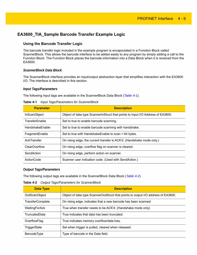
EA3600_TIA_Sample Barcode Transfer Example Logic
Using the Barcode Transfer Logic
The barcode transfer logic included in the example program is encapsulated in a Function Block called ScannerBlock. This allows the barcode interface to be added easily to any program by simply adding a call to the Function Block. The Function Block places the barcode information into a Data Block when it is received from the EA3600.
ScannerBlock Data Block
The ScannerBlock interface provides an input/output abstraction layer that simplifies interaction with the EA3600 I/O. The interface is described in this section.
Input Tags/Parameters
The following input tags are available in the ScannerBlock Data Block (Table 4-1).
Output Tags/Parameters
The following output tags are available in the ScannerBlock Data Block (Table 4-2).
Table 4-1 Input Tags/Parameters for ScannerBlock
Parameter Description
InScanObject Object of data type ScannerInStruct that points to Input I/O Address of EA3600.
TransferEnable Set to true to enable barcode scanning.
HandshakeEnable Set to true to enable barcode scanning with handshake.
FragmentEnable Set to true with HandshakeEnable to scan > 64 bytes.
AckTransfer On rising edge, the current transfer is ACK'd. (Handshake mode only.)
ClearOverflow On rising edge, overflow flag on scanner is cleared.
SendAction On rising edge, perform action on scanner.
ActionCode Scanner user indication code. (Used with SendAction.)
Table 4-2 Output Tags/Parameters for ScannerBlock
Data Type Description
OutScanObject Object of data type ScannerOutStruct that points to output I/O address of EA3600.
TransferComplete On rising edge, indicates that a new barcode has been scanned.
WaitingForAck True when transfer needs to be ACK'd. (Handshake mode only)
TruncatedData True indicates that data has been truncated.
OverflowFlag True indicates memory overflow/data loss.
TriggerState Set when trigger is pulled, cleared when released.
BarcodeType Type of barcode in the Data field.

4 - 10 EA3600 Network Connect Product Reference Guide
Calling the ScannerBlock
The following tags are required by the ScannerBlock. These tags must be assigned to the same I/O addresses of the EA3600 for data transfers to work correctly (Table 4-3).
DataLength Length of data scanned in the Data byte array.
Data Array of 1024 bytes that contains the barcode data.
Table 4-3 ScannerBlock Required Tags
Tag Description
InScanObject Data type ScannerInStruct. Must be set to the input I/O address of the EA3600.
OutScanObject Data type ScannerOutStruct. Must be set to the output I/O address of the EA3600.
Table 4-2 Output Tags/Parameters for ScannerBlock (Continued)
Data Type Description

Chapter 5 EtherNet/IP Interface
Introduction
This chapter provides information about I/O assemblies, I/O connections, steps to configure Rockwell Automation ControlLogix communication, and transferring barcode data from the EA3600.
Communications Profile
The EtherNet/IP interface on the EA3600 supports CIP Adapter functionality. The device is able to receive, or be the target of, I/O connections from a CIP Scanner, but is not able to originate connections itself.
The interface supports the Generic device profile. The Generic profile provides for all CIP objects that are required by the EtherNet/IP specification.
EDS File
The EtherNet/IP EDS file describes the Identity and I/O capabilities of the EA3600. The file is used by PLC configuration tools to configure the I/O connections and data tags used to communicate with the EA3600 over the EtherNet/IP network.
The latest EDS file can be acquired in the Industrial Ethernet Software Package. See Chapter 1, Initial Setup.
IMPORTANT Read Chapter 2, Ethernet Interface and Chapter 3, Barcode Transfer prior to this chapter. These chapters provide information about EA3600 behavior that spans all protocols.
IMPORTANT By default, the EA3600 Requested Packet Interval is set to 100 ms. The configurable range of RPI values is 10 ms to 1000 ms. Ladder logic operations that occur quicker than the RPI may result in lost transitions, therefore it is important that timers be used to indicate transitions to the EA3600. For example, if ladder logic toggles the SendAction bit with a pulse of 1 ms, the EA3600 may miss the rising edge and no action is taken.

5 - 2 EA3600 Network Connect Product Reference Guide
Supported Objects
The EtherNet/IP interface supports the following CIP objects:
• Identity
• Message Router
• TCP/IP Interface
• Ethernet Link
• Connection Manager
• Assembly.
TCP/IP Interface Object
The TCP/IP Interface object provides the ability to get and set TCP/IP configuration parameters. The IP address configuration may be set through the TCP/IP Interface object, but requires a device reset before any changes take effect.
Ethernet Link Object
The Ethernet Link object provides the ability to get link speed and duplex configuration parameters. The link configuration may not be changed through this object; all attributes are read-only.
I/O Assemblies
The EtherNet/IP interface includes two Assembly object instances that hold parameters and data used in the transfer of barcode data received from the scanner by the EA3600 to the controller.
Status and Barcode Data Assembly
Instance: 100/101
Access: Get
Size: 496 bytes
The Status and Barcode Data assembly holds the current status of the barcode transfer and the barcode data itself. The format of the assembly data follows that described in the Status and Barcode Data Assembly section above.
The Input Data field size 484 bytes.
Barcode Transfer Control Assembly
Instance: 150
Access: Get / Set
Size: 6 bytes
The Barcode Transfer Control assembly is used for handshaking during barcode transfer by the controller. The format of the assembly data follows that described in the Barcode Transfer Control Assembly section above.
NOTE The EtherNet/IP interface does not support EtherNet/IP Address Conflict Detection.
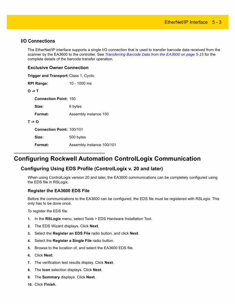
EtherNet/IP Interface 5 - 3
I/O Connections
The EtherNet/IP interface supports a single I/O connection that is used to transfer barcode data received from the scanner by the EA3600 to the controller. See Transferring Barcode Data from the EA3600 on page 5-15 for the complete details of the barcode transfer operation.
Exclusive Owner Connection
Trigger and Transport:Class 1, Cyclic
RPI Range: 10 - 1000 ms
O -> T
Connection Point: 150
Size: 6 bytes
Format: Assembly instance 150
T -> O
Connection Point: 100/101
Size: 500 bytes
Format: Assembly instance 100/101
Configuring Rockwell Automation ControlLogix Communication
Configuring Using EDS Profile (ControlLogix v. 20 and later)
When using ControlLogix version 20 and later, the EA3600 communications can be completely configured using the EDS file in RSLogix.
Register the EA3600 EDS File
Before the communications to the EA3600 can be configured, the EDS file must be registered with RSLogix. This only has to be done once.
To register the EDS file:
1. In the RSLogix menu, select Tools > EDS Hardware Installation Tool.
2. The EDS Wizard displays. Click Next.
3. Select the Register an EDS File radio button, and click Next.
4. Select the Register a Single File radio button.
5. Browse to the location of, and select the EA3600 EDS file.
6. Click Next.
7. The verification test results display. Click Next.
8. The Icon selection displays. Click Next.
9. The Summary displays. Click Next.
10. Click Finish.

5 - 4 EA3600 Network Connect Product Reference Guide
Add the EA3600 to the I/O Configuration
In order for the PLC to communicate with the EA3600, it must be added to the I/O configuration in the program.
To add the I/O configuration:
1. Expand the I/O Configuration tree in the Organizer pane to display the Ethernet network.
Figure 5-1 I/O Configuration Tree
2. Right-click on the Ethernet node in the tree and select New Module…
3. The Select Module Type dialog displays. Change the Vendor filter to only select Zebra Technologies. The EA3600 displays in the device list.
Figure 5-2 Select Module Type
NOTE In Figure 5-1, a 1756-EN2T is used as the Ethernet interface. This may be another type of Ethernet interface module depending on the application.
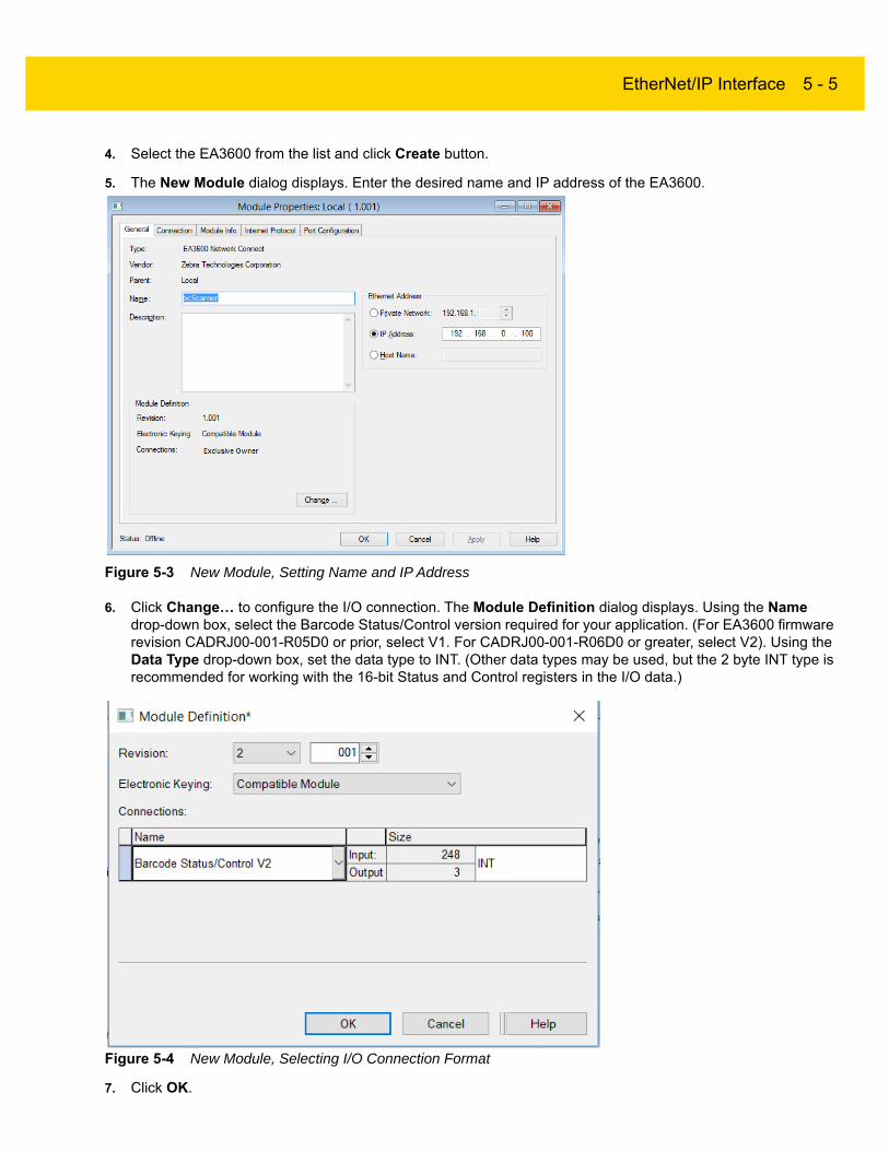
EtherNet/IP Interface 5 - 5
4. Select the EA3600 from the list and click Create button.
5. The New Module dialog displays. Enter the desired name and IP address of the EA3600.
Figure 5-3 New Module, Setting Name and IP Address
6. Click Change… to configure the I/O connection. The Module Definition dialog displays. Using the Name drop-down box, select the Barcode Status/Control version required for your application. (For EA3600 firmware revision CADRJ00-001-R05D0 or prior, select V1. For CADRJ00-001-R06D0 or greater, select V2). Using the Data Type drop-down box, set the data type to INT. (Other data types may be used, but the 2 byte INT type is recommended for working with the 16-bit Status and Control registers in the I/O data.)
Figure 5-4 New Module, Selecting I/O Connection Format
7. Click OK.

5 - 6 EA3600 Network Connect Product Reference Guide
8. Click Yes in the dialog warning about changing the module definition.
9. Click OK.
10. The EA3600 is added to the I/O configuration, and appears in the tree.
Figure 5-5 I/O Tree with EA3600 Added
All I/O connection parameters and I/O Tags are automatically configured when the module is added to the I/O Configuration.
EA3600 I/O Tags
When the EA3600 is added to the I/O configuration, a set of tags is created to allow the PLC logic to read and write data to the EA3600 through the I/O connection. Figure 5-6 shows the tags that are created.
Figure 5-6 EA3600 Related Tags
NOTE The tag names are based on the name that was configured in the New Module dialog when the EA3600 was added to the I/O Configuration. In the example in Figure 5-6, the module was named bcScanner.
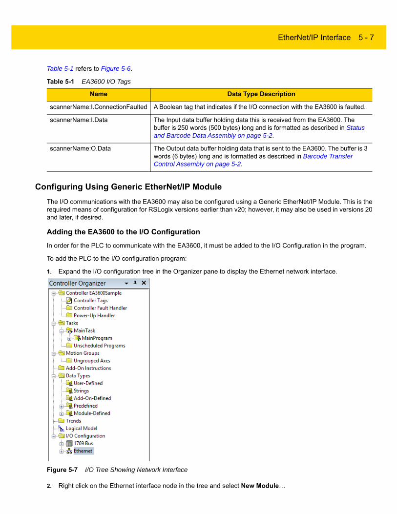
EtherNet/IP Interface 5 - 7
Table 5-1 refers to Figure 5-6.
Configuring Using Generic EtherNet/IP Module
The I/O communications with the EA3600 may also be configured using a Generic EtherNet/IP Module. This is the required means of configuration for RSLogix versions earlier than v20; however, it may also be used in versions 20 and later, if desired.
Adding the EA3600 to the I/O Configuration
In order for the PLC to communicate with the EA3600, it must be added to the I/O Configuration in the program.
To add the PLC to the I/O configuration program:
1. Expand the I/O configuration tree in the Organizer pane to display the Ethernet network interface.
Figure 5-7 I/O Tree Showing Network Interface
2. Right click on the Ethernet interface node in the tree and select New Module…
Table 5-1 EA3600 I/O Tags
Name Data Type Description
scannerName:I.ConnectionFaulted A Boolean tag that indicates if the I/O connection with the EA3600 is faulted.
scannerName:I.Data The Input data buffer holding data this is received from the EA3600. The buffer is 250 words (500 bytes) long and is formatted as described in Status and Barcode Data Assembly on page 5-2.
scannerName:O.Data The Output data buffer holding data that is sent to the EA3600. The buffer is 3 words (6 bytes) long and is formatted as described in Barcode Transfer Control Assembly on page 5-2.

5 - 8 EA3600 Network Connect Product Reference Guide
3. The Select Module Type dialog displays. Select the ETHERNET_MODULE Generic Ethernet Module entry and click OK.
Figure 5-8 Select Generic Module Type
4. The Module Properties dialog displays.
Figure 5-9 Module Properties for Generic Module Type
a. Enter the desired name for the EA3600.
b. Enter the IP address of the EA3600.
c. Set the Comm Format to Data - INT. (Other data types may be used, but the 2 byte INT type is recommended for working with the 16-bit Status and Control registers in the I/O data.)
d. Set the Connection Parameters as:
i. Input: Instance 101, size 248
ii. Output: Instance 150, size 3
iii. Config: Instance 3, size 0
e. Click Finish.
NOTE These sizes are based on 2 byte INT data types, if another data type is used, the sizes must be altered to translate to 496 bytes Input and 4 bytes Output.

EtherNet/IP Interface 5 - 9
5. The EA3600 is added to the I/O configuration and displays in the tree.
Figure 5-10 I/O Tree After EA3600 Add
EA3600 Tags
When the EA3600 is added to the I/O Configuration, a set of tags is created to allow the PLC logic to read and write data to the EA3600 through the I/O connection. Figure 5-11 displays the tags that are created.
Figure 5-11 Tags Created with Generic Module
Table 5-2 refers to Figure 5-10.
NOTE The tag names are based on the name that was configured in the Module Properties dialog when the EA3600 was added to the I/O Configuration. In the screen shot example the module was named bcScanner.
Table 5-2 EA3600 Tags
Tag Name Type Description
scannerName:C Unused configuration data. When a generic Ethernet module is added to the configuration, RSLogix automatically creates a configuration data buffer. In the case of the EA3600, this buffer is not used.
scannerName:I.Data The Input data buffer holding data this is received from the EA3600. The buffer is 248 words (496 bytes) long and is formatted as described in the Status and Barcode Data section.
scannerName:O.Data The Output data buffer holding data that is sent to the EA3600. The buffer is 3 words (6 bytes) long and is formatted as described in the Barcode Transfer Control Assembly section.

5 - 10 EA3600 Network Connect Product Reference Guide
Configuring Using the EA3600 Add On Profile
Installing the AOP
An Add On Profile (AOP) was developed for making development easier with the EA3600 and Logix Studio 5000 v24.
To install the EA3600 AOP:
1. Download and unzip the file ZT_BAR_Rel16_RELEASE_2.zip on the same computer that is running Logix Studio 5000.
2. Shutdown any running instances of Logix Studio 5000 and RSLinx Classic.
3. Run the executable file MPSetup.exe and click Next at the Welcome screen.
Figure 5-12 RSLogix 5000 Welcome Screen
4. Click Next after accepting the license agreement.
Figure 5-13 RSLogix 5000 License Agreement
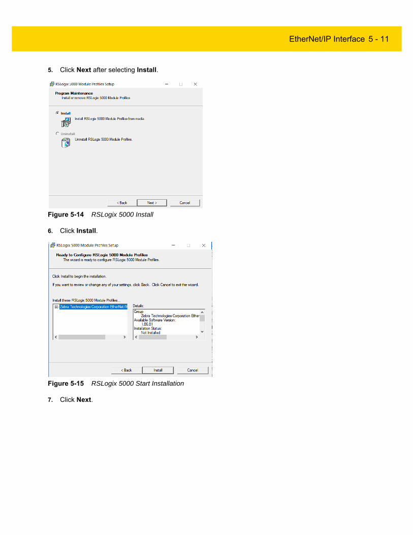
EtherNet/IP Interface 5 - 11
5. Click Next after selecting Install.
Figure 5-14 RSLogix 5000 Install
6. Click Install.
Figure 5-15 RSLogix 5000 Start Installation
7. Click Next.

5 - 12 EA3600 Network Connect Product Reference Guide
Figure 5-16 RSLogix 5000 Installing
8. Click Finish after the setup is complete
Figure 5-17 RSLogix 5000 Installing
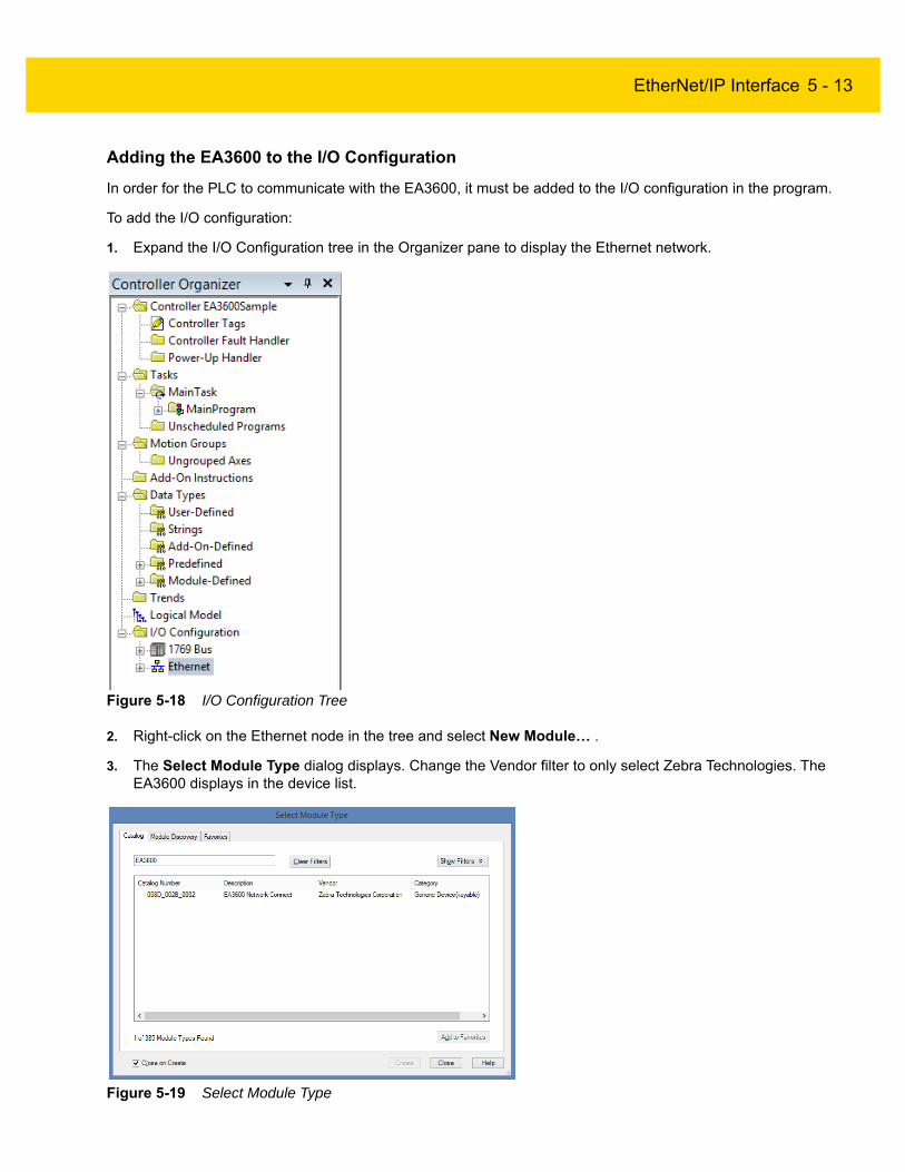
EtherNet/IP Interface 5 - 13
Adding the EA3600 to the I/O Configuration
In order for the PLC to communicate with the EA3600, it must be added to the I/O configuration in the program.
To add the I/O configuration:
1. Expand the I/O Configuration tree in the Organizer pane to display the Ethernet network.
Figure 5-18 I/O Configuration Tree
2. Right-click on the Ethernet node in the tree and select New Module… .
3. The Select Module Type dialog displays. Change the Vendor filter to only select Zebra Technologies. The EA3600 displays in the device list.
Figure 5-19 Select Module Type

5 - 14 EA3600 Network Connect Product Reference Guide
4. Select the EA3600 from the list and click Create button.
5. The New Module dialog displays. Enter the desired name and IP address of the EA3600.
Figure 5-20 New Module, Setting Name and IP Address
6. Click OK.
7. The EA3600 is added to the I/O configuration and appears in the tree.
Figure 5-21 EA3600 Added to the Tree
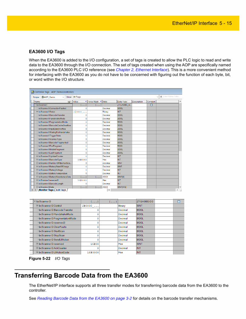
EtherNet/IP Interface 5 - 15
EA3600 I/O Tags
When the EA3600 is added to the I/O configuration, a set of tags is created to allow the PLC logic to read and write data to the EA3600 through the I/O connection. The set of tags created when using the AOP are specifically named according to the EA3600 PLC I/O reference (see Chapter 2, Ethernet Interface). This is a more convenient method for interfacing with the EA3600 as you do not have to be concerned with figuring out the function of each byte, bit, or word within the I/O structure.
Figure 5-22 I/O Tags
Transferring Barcode Data from the EA3600
The EtherNet/IP interface supports all three transfer modes for transferring barcode data from the EA3600 to the controller.
See Reading Barcode Data from the EA3600 on page 3-2 for details on the barcode transfer mechanisms.

5 - 16 EA3600 Network Connect Product Reference Guide
Sample Application for Logix Studio 5000 v24 With AOP
The EtherNet/IP sample application and scanner routine are located in the Industrial Ethernet Developer zip file (CAAEAS00-001-RXXD0.ZIP).
A single example project, EA3600Sample_AOP_v2.zip, for Logix Studio 5000 v24 is available that uses the ScannerRoutine to interface with the EA3600. This ScannerRoutine is also available as a separate archive (ScannerRoutine_AOP_v2.L5X ).
EA3600Sample Barcode Transfer Example Logic
Using the Barcode Transfer Logic
The barcode transfer logic included in the example program is encapsulated in a separate routine called ScannerRoutine. This allows the barcode interface to be added easily to any program by simply adding the routine and then jumping to it via the MainProgram. The ScannerRoutine adds a number of Local Tags that provide the interface for the EA3600 I/O.
ScannerRoutine
The ScannerRoutine Local tags provide an input/output abstraction layer that simplifies interaction with the EA3600 I/O. The tags are described in this section.
Table 5-3 Input Tags for ScannerRoutine
Parameter Description
TransferEnable Set to true to enable barcode scanning.
HandshakeEnable Set to true to enable barcode scanning with handshake.
FragmentEnable Set to true with HandshakeEnable to scan > 484 bytes.
AckTransfer On rising edge, the current transfer is ACK’d. (Handshake mode only.)
ClearOverflow On rising edge, overflow flag on scanner is cleared.
SendUIAction On rising edge, perform action on scanner.
ActionCode (INT) Scanner user indication code. (Used with SendUIAction.)
Table 5-4 Output Tags for ScannerRoutine
Data Type Description
TransferComplete On rising edge, indicates that a new barcode has been scanned.
WaitingForAck True when transfer needs to be ACK’d. (Handshake mode only)
TruncatedData True indicates that data has been truncated.
OverflowFlag True indicates memory overflow/data loss.
TriggerState Set when trigger is pulled, cleared when released.
DataType Type of barcode in the Data field.

EtherNet/IP Interface 5 - 17
DataLength Length of data scanned in the Data byte array.
Data Array of 1024 bytes that contains the barcode data.
Table 5-4 Output Tags for ScannerRoutine (Continued)
Data Type Description

5 - 18 EA3600 Network Connect Product Reference Guide

Chapter 6 Modbus TCP Interface
Introduction
Communications Profile
This chapter provides information about using the Modbus TCP interface to transfer barcode data from the EA3600.
The Modbus TCP interface on theEA3600 supports Modbus TCP server / slave functionality. The device is able to receive, or be the target of, I/O connections from a Modbus TCP client / master, but is not able to originate connections itself.
Modbus Unit Identifier
The Unit Identifier (or slave identifier) should be set to 1 for all Modbus TCP requests sent to the EA3600.
Supported Modbus Functions
The following Modbus TCP function codes are supported by the EA3600.
IMPORTANT Read Chapter 2, Ethernet Interface and Chapter 3, Barcode Transfer prior to this chapter. These chapters provide information about EA3600 behavior that spans all protocols.
Table 6-1 Program Tags
Code Function Description
03 Read Holding Registers Read from up to 125 Holding registers from a given starting address.
04 Read Input Registers Read from up to 125 Input registers from a given starting address.
06 Write Single Register Write a single Holding register.
16 Write Multiple Registers Write into up to 125 Holding registers from a given starting address.

6 - 2 EA3600 Network Connect Product Reference Guide
Modbus Register Mapping
The Modbus TCP interface provides access to registers that hold parameters and data used in the transfer of barcode data read by the EA3600 to the controller.
EA3600 Identity and Version Information Registers
Register Type: Input
Register Range: 1 - 42
Access Functions: (04) Read Input Registers
The Identity and Version registers hold information about the EA3600 device and its software. The registers are mapped as shown in Table 6-2.
Status and Barcode Data Registers
Register Type: Input
Register Range: 200 - 2255
Access Functions: (04) Read Input Registers
The Status and Barcode Data registers holds the current status of the barcode transfer and the barcode data itself. The format of the register data follows the description above. The register mapping of each Input Data field is defined in Table 6-3.
Table 6-2 Identity and Version Registers
EA3600 Identity and Version Register Mapping
Register Address
Register Count Parameter Data
TypeDescription
1 1 Firmware Revision UINT16 High byte is the Major revision. Low byte is the Minor revision.
2 16 Serial Number String The serial number of the EA3600.
18 25 Product Name String The EA3600 product / model name.
NOTE Modbus TCP limits register transfers to up to 125 bytes long. To read all of the barcode data for larger barcodes (up to 4096 bytes or 2048 words of data), it may be necessary to make multiple reads. For example, read the 125 registers starting at address 200, read 125 registers starting at address 325, and so on.
Table 6-3 Status and Barcode Data Registers
Status and Barcode Data Register Mapping
Register Address Register Count Field
200 1 Status Register
201 1 Update Counter
202 1 Barcode Type
203 4 Reserved

Modbus TCP Interface 6 - 3
Barcode Transfer Control Registers
Register Type: Holding
Register Range: 1 - 3
Access Functions: (03) Read Holding Registers
(06) Write Single Register
(16) Write Multiple Registers
The Barcode Transfer Control register is used for handshaking during barcode transfer by the controller. The format of the register data follows that described in Barcode Output Data on page 2-6. The register mapping of each Output Data field is defined in Table 6-4.
Transferring Barcode Data from the EA3600
The Modbus TCP interface supports Basic Mode and Handshake Mode transfers from the EA3600 to the controller. Fragmentation Mode is not required because the Modbus register data supports up to 4096 bytes of barcode data which is the largest barcode that the EA3600 interface supports.
See Reading Barcode Data from the EA3600 on page 3-2 for details on the barcode transfer mechanisms.
Example Barcode Transfer Register Commands
When using the Modbus TCP protocol, all interaction between the controller and EA3600 is done through register read and write commands. This section discusses the register command sequences required to perform typical barcode transfers.
207 1 Length
208 2048 Data
Table 6-3 Status and Barcode Data Registers
Status and Barcode Data Register Mapping
Register Address Register Count Field
NOTE The Input Data field length is 4096 bytes.
Table 6-4 Register Mapping of Each Output Data Field
Barcode Transfer Control Register Mapping
Register Address Register Count Parameter
1 1 Control Register
2 1 ACK Counter
3 1 UI Action Code
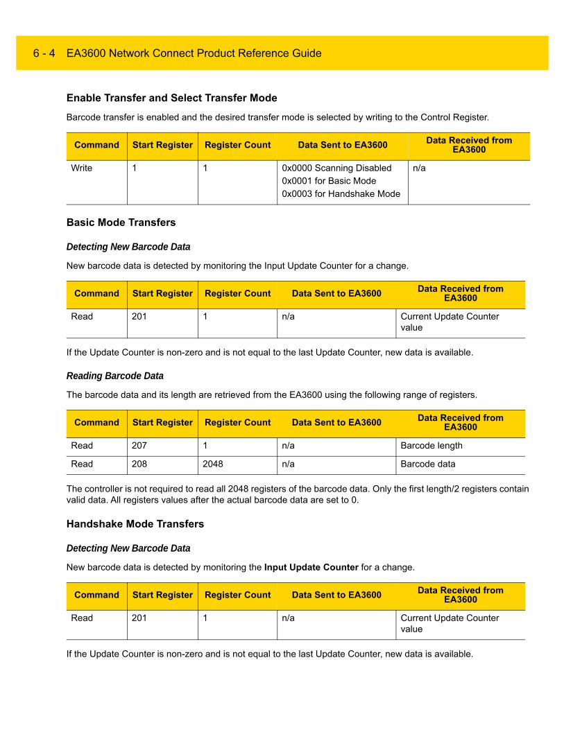
6 - 4 EA3600 Network Connect Product Reference Guide
Enable Transfer and Select Transfer Mode
Barcode transfer is enabled and the desired transfer mode is selected by writing to the Control Register.
Basic Mode Transfers
Detecting New Barcode Data
New barcode data is detected by monitoring the Input Update Counter for a change.
If the Update Counter is non-zero and is not equal to the last Update Counter, new data is available.
Reading Barcode Data
The barcode data and its length are retrieved from the EA3600 using the following range of registers.
The controller is not required to read all 2048 registers of the barcode data. Only the first length/2 registers contain valid data. All registers values after the actual barcode data are set to 0.
Handshake Mode Transfers
Detecting New Barcode Data
New barcode data is detected by monitoring the Input Update Counter for a change.
If the Update Counter is non-zero and is not equal to the last Update Counter, new data is available.
Command Start Register Register Count Data Sent to EA3600 Data Received from EA3600
Write 1 1 0x0000 Scanning Disabled
0x0001 for Basic Mode
0x0003 for Handshake Mode
n/a
Command Start Register Register Count Data Sent to EA3600 Data Received from EA3600
Read 201 1 n/a Current Update Counter value
Command Start Register Register Count Data Sent to EA3600 Data Received from EA3600
Read 207 1 n/a Barcode length
Read 208 2048 n/a Barcode data
Command Start Register Register Count Data Sent to EA3600 Data Received from EA3600
Read 201 1 n/a Current Update Counter value

Modbus TCP Interface 6 - 5
Reading and Acknowledging Barcode Data
The barcode data and its length are retrieved from the EA3600 using the following range of registers.
The controller is not required to read all 2048 registers of the barcode data. Only the first length/2 registers contain valid data. All registers values after the actual barcode data are set to 0.
Once the controller has read the barcode data, it must indicate to the EA3600 that it is safe to write the next barcode's data into the registers. This is done by setting the Output ACK Counter to match the Input Update Counter.
Handshake Resynchronization
If the EA3600 detects an issue with the transfer (connection is broken, controller stopped, etc.) it sets the Input Update Counter to 0. The barcode transfer to the controller stops until the controller writes a 0 into the Output ACK Counter.
Once both counters are 0, transfer of barcode data resumes.
Command Start Register Register Count Data Sent to EA3600 Data Received from EA3600
Read 207 1 n/a Barcode length
Read 208 2048 n/a Barcode data
Command Start Register Register Count Data Sent to EA3600 Data Received from EA3600
Write 2 1 Current Input Update Counter value
n/a
Command Start Register Register Count Data Sent to EA3600 Data Received from EA3600
Write 2 1 0000 n/a

6 - 6 EA3600 Network Connect Product Reference Guide
Chapter 7 TCP/IP Interface
Introduction
In addition to the industrial Ethernet protocols described in previous chapters, the EA3600 also provides support for communication over standard TCP/IP. This chapter provides the information necessary to obtain barcode data from the EA3600 through standard TCP/IP transfers.
Finding Devices
The EA3600 acts as a server in the Client/Server network model. By listening for a UDP broadcast packet on a specific port, the device provides a mechanism for programmatically determining what EA3600 devices are available on the network.
Broadcast Send Packet Details From the Host
• Packet Protocol: UDP
• Source Address: <IP Address of Host>
• Destination Address: Broadcast (255.255.255.255)
• Source Port: <Any, but response will be sent to this port>
• Destination Port: 12362
• Payload (C/C++ string): "MVP\x0d"
NOTE By default, the EA3600 is configured to obtain its IP address using DHCP. This chapter assumes that DHCP is used. It is also assumed that the host computer and the EA3600 are on the same network and within the same subnet.

7 - 2 EA3600 Network Connect Product Reference Guide
Unicast Receive Packet Details From the Device
• Packet Protocol: UDP
• Source Address: <IP Address of Device>
• Destination Address: <IP Address of Host>
• Source Port: 12362
• Destination Port: <Same as source port in broadcast packet>
• Payload (C/C++ string): "MAC=xx:xx:xx:xx:xx:xxPORT=YYYYY"
Where xx:xx:xx:xx:xx:xx is the MAC address of the device and YYYYY is the port address that the device is currently set to use.
After sending the Broadcast packet as defined above, the devices on the network will all respond with the Unicast packet also defined above. Multiple responses (usually 3) may be received from the same
Receiving Barcode Data
By default, the EA3600 sends barcode data via TCP packets to a connected client on port 54321. This port is configurable. The example below uses the default port value.
C# Connection Source Code Example (where ipAddress is address of the EA3600):
IPEndPoint bcScanner = new IPEndPoint(ipAddress, 54321);
Socket skt = new Socket(AddressFamily.InterNetwork, SocketType.Stream, ProtocolType.Tcp);
skt.Connect(bcScanner);
Barcode receive packets are defined below.
Unicast Receive Packet Details From the Device
• Packet Protocol: TCP
• Source Address: <IP Address of Device>
• Destination Address: <IP Address of Host>
• Source Port: 54321
• Destination Port: <Any, specified during connection>
• Payload (Byte array): <Bar code data>

TCP/IP Interface 7 - 3
Zebra TCP/IP Sample Application
This sample application is written in C# using Visual Studio 2015 and targets the .NET Framework v2.0. Both source code and executable binaries are provided. Figure 7-1 displays the UI for the sample application.
Figure 7-1 Sample Application UI
The Find Devices button sends a broadcast packet and receives responses from all the Zebra EA3600 devices on the network. They are then listed in the Device Selection combo list box. Once the list is populated with valid devices, the Connect button is enabled.
Figure 7-2 Sample Application UI
Select Connect to receive scanned barcode data. On a valid connection, the red button turns green.

7 - 4 EA3600 Network Connect Product Reference Guide
Notes About the Other UI Elements
• Scanned barcode data is displayed in the Bar code data: text box.
• Select Show non-printable chars to show them as human readable text when scanned.
• Select Enable Keyboard Wedge to send scanned data to the top most window of the host PC.
• Select Clear data to clear the data in the Bar code data: text box.
• Select Disconnect to close the connection between the device and host.
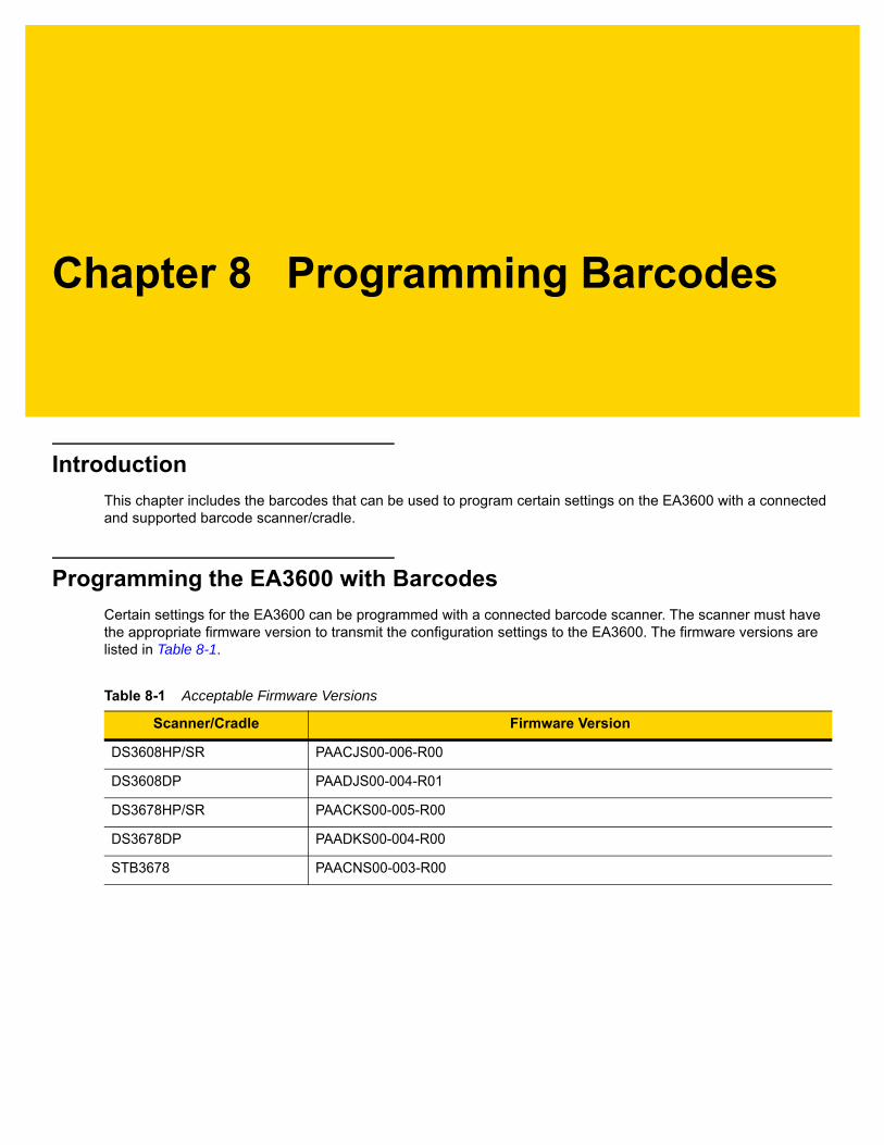
Chapter 8 Programming Barcodes
Introduction
This chapter includes the barcodes that can be used to program certain settings on the EA3600 with a connected and supported barcode scanner/cradle.
Programming the EA3600 with Barcodes
Certain settings for the EA3600 can be programmed with a connected barcode scanner. The scanner must have the appropriate firmware version to transmit the configuration settings to the EA3600. The firmware versions are listed in Table 8-1.
Table 8-1 Acceptable Firmware Versions
Scanner/Cradle Firmware Version
DS3608HP/SR PAACJS00-006-R00
DS3608DP PAADJS00-004-R01
DS3678HP/SR PAACKS00-005-R00
DS3678DP PAADKS00-004-R00
STB3678 PAACNS00-003-R00

8 - 2 EA3600 Network Connect Product Reference Guide
EA3600 Parameter Pass-Through
The scanner must be programmed to transmit parameters to the EA3600. Scan one of the following barcodes to enable or disable this feature on the scanner. The default is Disable EA3600 Parameter Pass-Through.
Enable EA3600 Parameter Pass-Through
* Disable EA3600 Parameter Pass-Through
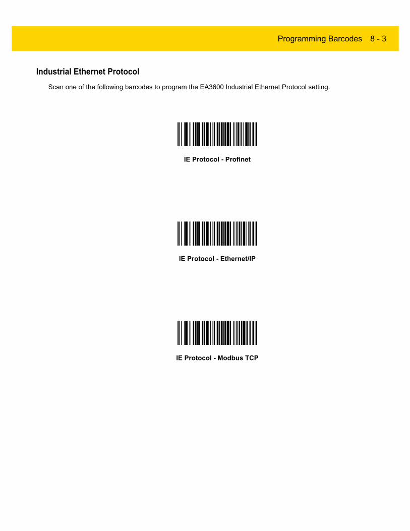
Programming Barcodes 8 - 3
Industrial Ethernet Protocol
Scan one of the following barcodes to program the EA3600 Industrial Ethernet Protocol setting.
IE Protocol - Profinet
IE Protocol - Ethernet/IP
IE Protocol - Modbus TCP

8 - 4 EA3600 Network Connect Product Reference Guide
Transmit Length and Code Type over TCP/IP
To enable or disable the transmission of the length and code type bytes over standard TCP/IP, scan the appropriate barcode below. The default is Do Not Transmit Length and Code Type over TCP/IP.
* Transmit Length and Code Type over TCP/IP
Do Not Transmit Length and Code Type over TCP/IP
Additional Configuration Settings with Barcodes
There are several other EA3600 settings that can be programmed by creating unique barcodes following a certain format. These settings are:
• DHCP Timeout
• Static IP Address
• Gateway
• Subnet
• Profinet Name
• TCP/IP Port
It is recommended to use the Zebra Ethernet Configuration Utility to program these settings. For more information on creating programming barcodes for these settings, contact the Zebra Support Center.

Appendix A Troubleshooting
Troubleshooting
Table A-1 Troubleshooting the EA3600
Symptom Potential Issue Solution
Find devices fails EA3600 is not connected to the network, or powered on.
Verify that the Ethernet Jack Status LED on the EA3600 is on (the EA3600 has power) and the Ethernet cable is plugged into the EA3600, and into a network switch. Both Ethernet lights on the EA3600 should be on.
EA3600 is unable to get a valid IP address through DHCP.
Verify that the network the EA3600 is plugged into is also connected to a DHCP server that has available addresses in its address pool.
EA3600 is set to an IP address that is not accessible on the PC subnet.
Reset to factory defaults by pressing the Reset button (see Reset Button on page 1-2) to recycle power to the EA3600. Try again.
Note: This will not fix the issue if the PC subnet is not 192.168.0.
Sample applications not loading The sample applications were created with the following software packages: TIA v15.1 SP1 or Logix Studio 5000 v24. Only these packages, or later versions are able to load them.
If your TIA or Logix development environment cannot load the sample application(s), then sample application(s) should be recreated using the information provided in this guide.

A - 2 EA3600 Network Connect Product Reference Guide
Cannot connect PLC to the EA3600 For PROFINET, the EA3600 needs to be assigned a device name that matches the one used in the application.
Assign a PROFINET device name through TIA (see Setting the PROFINET Device Name on page 4-7.
Note: If you are using Step 7, ensure the PROFINET device name is all lower case.
Scanner emits red LED and high/low error beeps when scanning barcodes
This occurs when the EA3600 is not connected to the Zebra Industrial Ethernet Utility and barcodes are scanned.
Connect to the EA3600 through the utility. Barcode data displays in the Status Log.
PLC has not enabled transfers. For barcode data to be sent to the PLC, the PLC must have the EA3600 Ctrl_EnableTransfer bit set.
Unable to load firmware An error occurred during a firmware update.
Recycle power to the EA3600. Connect and try again.
Table A-1 Troubleshooting the EA3600 (Continued)
Symptom Potential Issue Solution

Index
B
barcodetransfer mode selection with handshake
mode and frag mode bits . . . . . . . . . . . . 3-2transfer modes . . . . . . . . . . . . . . . . . . . . . . . . . . 3-1
barcodesIE protocol - Ethernet/IP . . . . . . . . . . . . . . . . . . . 8-3IE protocol - Modbus TCP . . . . . . . . . . . . . . . . . . 8-3IE protocol - Profinet . . . . . . . . . . . . . . . . . . . . . . 8-3parameter pass-through . . . . . . . . . . . . . . . . . . . 8-2transmit length and code type
over TCP/IP . . . . . . . . . . . . . . . . . . . . . . 8-4bullets . . . . . . . . . . . . . . . . . . . . . . . . . . . . . . . . . . . . . viii
C
configuration utilityconnect/disconnect dialog . . . . . . . . . . . . . . .1-6, 1-7
conventionsnotational . . . . . . . . . . . . . . . . . . . . . . . . . . . . . . . viii
D
default settings . . . . . . . . . . . . . . . . . . . . . . . . . . . . . 1-2device definition files . . . . . . . . . . . . . . . . . . . . . . . . . 2-2
E
EDS file . . . . . . . . . . . . . . . . . . . . . . . . . . . . . . . .5-1, 5-3EtherNet/IP
device definition file . . . . . . . . . . . . . . . . . . . . . . . 2-2EA3600 I/O tags . . . . . . . . . . . . . . . . . . . . . . . . . 5-7EA3600 tags . . . . . . . . . . . . . . . . . . . . . . . . . . . . 5-9interface . . . . . . . . . . . . . . . . . . . . . . . . . . . . . . . 5-1prerequisites . . . . . . . . . . . . . . . . . . . . . . . . . . . . 1-1setting IP address config . . . . . . . . . . . . . . . . . . . 2-2
F
filesEDS . . . . . . . . . . . . . . . . . . . . . . . . . . . . . . . 5-1, 5-3GSDML . . . . . . . . . . . . . . . . . . . . . . . . . . . . . 4-1, 4-2industrial protocol . . . . . . . . . . . . . . . . . . . . . . . . 2-2sample application . . . . . . . . . . . . . . . . . . . . . . . 2-3sample function block/library/routine files . . . . . . 2-3
G
GSDML file . . . . . . . . . . . . . . . . . . . . . . . . . . . . . 4-1, 4-2
H
hardware prerequisites . . . . . . . . . . . . . . . . . . . . . . . 1-1
I
identity registers, Modbus TCP . . . . . . . . . . . . . . . . . 6-2indications, status . . . . . . . . . . . . . . . . . . . . . . . . . . . 1-3information, service . . . . . . . . . . . . . . . . . . . . . . . . . . . . ix
M
Modbus TCPbarcode data registers . . . . . . . . . . . . . . . . . . . . 6-2detecting new barcode data . . . . . . . . . . . . . . . . 6-4handshake resynchronization . . . . . . . . . . . . . . . 6-5identity and version registers . . . . . . . . . . . . . . . 6-2interface . . . . . . . . . . . . . . . . . . . . . . . . . . . . . . . 6-1prerequisites . . . . . . . . . . . . . . . . . . . . . . . . . . . . 1-1program tags . . . . . . . . . . . . . . . . . . . . . . . . . . . 6-1reading and acknowledging
barcode data . . . . . . . . . . . . . . . . . . . . . 6-5register mapping . . . . . . . . . . . . . . . . . . . . . . . . . 6-3setting IP address config . . . . . . . . . . . . . . . . . . 2-2

Index - 2 EA3600 Network Connect Product Reference Guide
P
prerequisiteshardware . . . . . . . . . . . . . . . . . . . . . . . . . . . . . . . 1-1software . . . . . . . . . . . . . . . . . . . . . . . . . . . . . . . 1-1
PROFINETbarcode handling function
block data types . . . . . . . . . . . . . . . . . . . 4-9data block tags . . . . . . . . . . . . . . . . . . . . . . . . . 4-10device definition file . . . . . . . . . . . . . . . . . . . . . . . 2-2interface . . . . . . . . . . . . . . . . . . . . . . . . . . . . . . . 4-1parameters in BarcodeHandler
function block . . . . . . . . . . . . . . . . . . . . . 4-9prerequisites . . . . . . . . . . . . . . . . . . . . . . . . . . . . 1-1setting IP address config . . . . . . . . . . . . . . . . . . . 2-2
program tags, Modbus TCP . . . . . . . . . . . . . . . . . . . 6-1programming the device
industrial ethernet protocol . . . . . . . . . . . . . . . . . 8-3other configuration settings . . . . . . . . . . . . . . . . . 8-4pass-through . . . . . . . . . . . . . . . . . . . . . . . . . . . . 8-2transmit length/code type over TCP/IP . . . . . . . . 8-4
R
register mapping, Modbus TCP . . . . . . . . . . . . . . . . . 6-3related documents . . . . . . . . . . . . . . . . . . . . . . . . . . . . .ixrelated software . . . . . . . . . . . . . . . . . . . . . . . . . . . . . . .ixreset button . . . . . . . . . . . . . . . . . . . . . . . . . . . . . . . . 1-2
S
screensconnect/disconnect dialog . . . . . . . . . . . . . . .1-6, 1-7
settingsfactory default . . . . . . . . . . . . . . . . . . . . . . . . . . . 1-2reset button . . . . . . . . . . . . . . . . . . . . . . . . . . . . . 1-2
software package, Zebraindustrial ethernet . . . . . . . . . . . . . . . . . . . . .4-1, 5-1
software prerequisites . . . . . . . . . . . . . . . . . . . . . . . . 1-1status data registers, Modbus TCP . . . . . . . . . . . . . . 6-2status indications . . . . . . . . . . . . . . . . . . . . . . . . . . . . 1-3
T
TCP/IPbroadcast send packet details from host . . . . . . 7-1find devices . . . . . . . . . . . . . . . . . . . . . . . . . . . . . 7-1receive barcode data . . . . . . . . . . . . . . . . . . . . . 7-2sample app . . . . . . . . . . . . . . . . . . . . . . . . . . . . . 7-3unicast receive packet details from device . . . . . 7-2
V
version registers, Modbus TCP . . . . . . . . . . . . . . . . . 6-2


MN-003001-04 Revision A - April 2019
Zebra Technologies Corporation, Inc.3 Overlook PointLincolnshire, IL 60069, U.S.A.http://www.zebra.com
ZEBRA and the stylized Zebra head are trademarks of Zebra Technologies Corporation, registered in many jurisdictions worldwide. All other trademarks are the property of their respective owners. ©2019 Zebra Technologies Corporation and/or its affiliates. All rights reserved..