E96-216 Configuration Port Module Infi90 Documentation/IMCPM01.pdf · WARNING notices as used in...
21
® ® Process Control and Automation Solutions from Elsag Bailey Group E96-216 Configuration Port Module (IMCPM01)
Transcript of E96-216 Configuration Port Module Infi90 Documentation/IMCPM01.pdf · WARNING notices as used in...
®®
E96-216
Configuration Port Module(IMCPM01)
Process Control andAutomation Solutionsfrom Elsag Bailey Group

WARNING notices as used in this instruction apply to hazards or unsafe practices that could result inpersonal injury or death.
CAUTION notices apply to hazards or unsafe practices that could result in property damage.
NOTES highlight procedures and contain information that assists the operator in understanding theinformation contained in this instruction.
WARNING
INSTRUCTION MANUALSDO NOT INSTALL, MAINTAIN, OR OPERATE THIS EQUIPMENT WITHOUT READING, UNDERSTANDING,AND FOLLOWING THE PROPER Elsag Bailey INSTRUCTIONS AND MANUALS; OTHERWISE, INJURY ORDAMAGE MAY RESULT.
RADIO FREQUENCY INTERFERENCEMOST ELECTRONIC EQUIPMENT IS INFLUENCED BY RADIO FREQUENCY INTERFERENCE (RFI). CAU-TION SHOULD BE EXERCISED WITH REGARD TO THE USE OF PORTABLE COMMUNICATIONS EQUIP-MENT IN THE AREA AROUND SUCH EQUIPMENT. PRUDENT PRACTICE DICTATES THAT SIGNSSHOULD BE POSTED IN THE VICINITY OF THE EQUIPMENT CAUTIONING AGAINST THE USE OF POR-TABLE COMMUNICATIONS EQUIPMENT.
POSSIBLE PROCESS UPSETSMAINTENANCE MUST BE PERFORMED ONLY BY QUALIFIED PERSONNEL AND ONLY AFTER SECURINGEQUIPMENT CONTROLLED BY THIS PRODUCT. ADJUSTING OR REMOVING THIS PRODUCT WHILE IT ISIN THE SYSTEM MAY UPSET THE PROCESS BEING CONTROLLED. SOME PROCESS UPSETS MAYCAUSE INJURY OR DAMAGE.
AVERTISSEMENT
MANUELS D’OPÉRATIONNE PAS METTRE EN PLACE, RÉPARER OU FAIRE FONCTIONNER L’ÉQUIPEMENT SANS AVOIR LU,COMPRIS ET SUIVI LES INSTRUCTIONS RÉGLEMENTAIRES DE Elsag Bailey . TOUTE NÉGLIGENCE ÀCET ÉGARD POURRAIT ÊTRE UNE CAUSE D’ACCIDENT OU DE DÉFAILLANCE DU MATÉRIEL.
PERTURBATIONS PAR FRÉQUENCE RADIOLA PLUPART DES ÉQUIPEMENTS ÉLECTRONIQUES SONT SENSIBLES AUX PERTURBATIONS PARFRÉQUENCE RADIO. DES PRÉCAUTIONS DEVRONT ÊTRE PRISES LORS DE L’UTILISATION DU MATÉ-RIEL DE COMMUNICATION PORTATIF. LA PRUDENCE EXIGE QUE LES PRÉCAUTIONS À PRENDREDANS CE CAS SOIENT SIGNALÉES AUX ENDROITS VOULUS DANS VOTRE USINE.
PERTURBATIONS DU PROCÉDÉL’ENTRETIEN DOIT ÊTRE ASSURÉ PAR UNE PERSONNE QUALIFIÉE EN CONSIDÉRANT L’ASPECTSÉCURITAIRE DES ÉQUIPEMENTS CONTRÔLÉS PAR CE PRODUIT. L’AJUSTEMENT ET/OU L’EXTRAC-TION DE CE PRODUIT PEUT OCCASIONNER DES À-COUPS AU PROCÉDÉ CONTRÔLE LORSQU’IL ESTINSÉRÉ DANS UNE SYSTÈME ACTIF. CES À-COUPS PEUVENT ÉGALEMENT OCCASIONNER DESBLESSURES OU DES DOMMAGES MATÉREILS.
NOTICE
The information contained in this document is subject to change without notice.
Elsag Bailey, its affiliates, employees, and agents, and the authors and contributors to this publication specif-ically disclaim all liabilities and warranties, express and implied (including warranties of merchantability andfitness for a particular purpose), for the accuracy, currency, completeness, and/or reliability of the informationcontained herein and/or for the fitness for any particular use and/or for the performance of any material and/or equipment selected in whole or part with the user of/or in reliance upon information contained herein.Selection of materials and/or equipment is at the sole risk of the user of this publication.
This document contains proprietary information of Elsag Bailey, Elsag Bailey Process Automation, andis issued in strict confidence. Its use, or reproduction for use, for the reverse engineering, developmentor manufacture of hardware or software described herein is prohibited. No part of this document may bephotocopied or reproduced without the prior written consent of Elsag Bailey.
I-E96-216A
Preface
The Configuration Port Moudle (IMCPM01) connects the Con-figuration and Tuning Terminal (CTT01/CTT02) to theINFI 90®/Network 90® system.
This manual explains the purpose, operation and maintenanceof the CPM module. It addresses handling precautions andinstallation procedures.
System engineers and technicians should read this manualbefore installing and operating the CPM module. A moduleSHOULD NOT be put into operation until this instruction isread and understood.
® INFI 90 and Network 90 are registered trademarks of Elsag Bailey Process Automation.

®
List of Effective Pages
Total number of pages in this instruction is 18, consisting of the following:
Page No. Change Date
Preface OriginalList of Effective Pages Original
iii through v Original1-1 through 1-4 Original2-1 through 2-2 Original3-1 through 3-3 Original4-1 through 4-2 Original5-1 Original6-1 Original
When an update is received, insert the latest changed pages and dispose of the super-seded pages.
NOTE: On an update page, the changed text or table is indicated by a vertical bar in the outer mar-gin of the page adjacent to the changed area. A changed figure is indicated by a vertical bar in theouter margin next to the figure caption. The date the update was prepared will appear beside thepage number.
I-E96-216A
I-E96-216A
Safety Summary
Sommaire de Securite
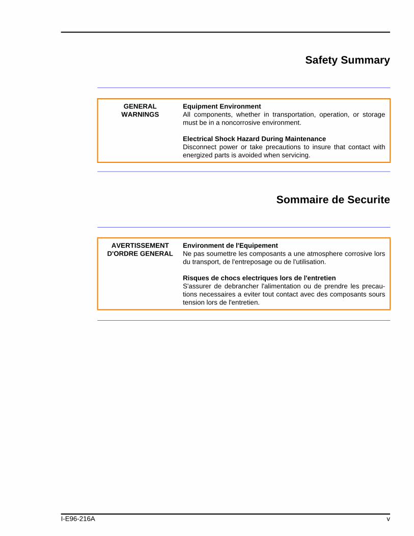
GENERALWARNINGS
Equipment EnvironmentAll components, whether in transportation, operation, or storagemust be in a noncorrosive environment.
Electrical Shock Hazard During MaintenanceDisconnect power or take precautions to insure that contact withenergized parts is avoided when servicing.
AVERTISSEMENT D'ORDRE GENERAL
Environment de l'EquipementNe pas soumettre les composants a une atmosphere corrosive lorsdu transport, de l'entreposage ou de l'utilisation.
Risques de chocs electriques lors de l'entretienS'assurer de debrancher l'alimentation ou de prendre les precau-tions necessaires a eviter tout contact avec des composants sourstension lors de l'entretien.
v
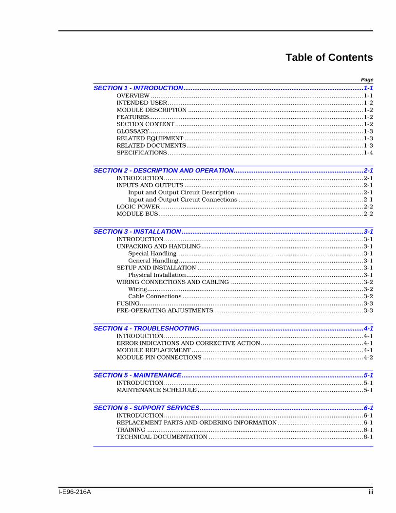
Table of Contents
I-E96-216A
Page
SECTION 1 - INTRODUCTION....................................................................................................1-1OVERVIEW ..................................................................................................................1-1INTENDED USER.........................................................................................................1-2MODULE DESCRIPTION ..............................................................................................1-2FEATURES...................................................................................................................1-2SECTION CONTENT .....................................................................................................1-2GLOSSARY...................................................................................................................1-3RELATED EQUIPMENT ................................................................................................1-3RELATED DOCUMENTS...............................................................................................1-3SPECIFICATIONS.........................................................................................................1-4
SECTION 2 - DESCRIPTION AND OPERATION........................................................................2-1INTRODUCTION...........................................................................................................2-1INPUTS AND OUTPUTS ................................................................................................2-1
Input and Output Circuit Description ....................................................................2-1Input and Output Circuit Connections ...................................................................2-1
LOGIC POWER.............................................................................................................2-2MODULE BUS..............................................................................................................2-2
SECTION 3 - INSTALLATION .....................................................................................................3-1INTRODUCTION...........................................................................................................3-1UNPACKING AND HANDLING.......................................................................................3-1
Special Handling....................................................................................................3-1General Handling...................................................................................................3-1
SETUP AND INSTALLATION .........................................................................................3-1Physical Installation...............................................................................................3-1
WIRING CONNECTIONS AND CABLING .......................................................................3-2Wiring....................................................................................................................3-2Cable Connections .................................................................................................3-2
FUSING........................................................................................................................3-3PRE-OPERATING ADJUSTMENTS ................................................................................3-3
SECTION 4 - TROUBLESHOOTING...........................................................................................4-1INTRODUCTION...........................................................................................................4-1ERROR INDICATIONS AND CORRECTIVE ACTION.......................................................4-1MODULE REPLACEMENT ............................................................................................4-1MODULE PIN CONNECTIONS ......................................................................................4-2
SECTION 5 - MAINTENANCE.....................................................................................................5-1INTRODUCTION...........................................................................................................5-1MAINTENANCE SCHEDULE.........................................................................................5-1
SECTION 6 - SUPPORT SERVICES...........................................................................................6-1INTRODUCTION...........................................................................................................6-1REPLACEMENT PARTS AND ORDERING INFORMATION ..............................................6-1TRAINING ....................................................................................................................6-1TECHNICAL DOCUMENTATION ...................................................................................6-1
iii

No. Title Page
List of Tables
®
4-1. P1 Pin Connections ............................................................................................... 4-25-1. Maintenance Schedule........................................................................................... 5-1
List of Figures
No. Title Page
1-1. IMCPM01 Application Example.............................................................................. 1-12-1. Configuration Port Module..................................................................................... 2-12-2. IMCPM01 Input/Output Circuit ............................................................................ 2-23-1. IMCPM01 Cable Connections and Termination ...................................................... 3-24-1. IMCPM01 Fuse Location ........................................................................................ 4-2
iv I-E96-216A
SECTION 1 - INTRODUCTION
I-E96-216A
OVERVIEW
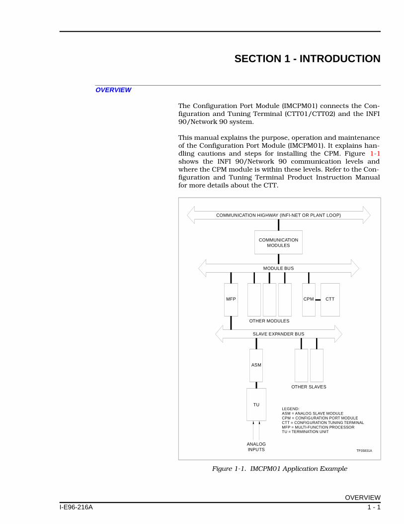
The Configuration Port Module (IMCPM01) connects the Con-figuration and Tuning Terminal (CTT01/CTT02) and the INFI90/Network 90 system.
This manual explains the purpose, operation and maintenanceof the Configuration Port Module (IMCPM01). It explains han-dling cautions and steps for installing the CPM. Figure 1-1shows the INFI 90/Network 90 communication levels andwhere the CPM module is within these levels. Refer to the Con-figuration and Tuning Terminal Product Instruction Manualfor more details about the CTT.
Figure 1-1. IMCPM01 Application Example
COMMUNICATION HIGHWAY (INFI-NET OR PLANT LOOP)
MODULE BUS
MFP CPM CTT
ASM
TU
ANALOGINPUTS
OTHER MODULES
OTHER SLAVES
SLAVE EXPANDER BUS
COMMUNICATIONMODULES
TP35831A
LEGEND:ASM = ANALOG SLAVE MODULECPM = CONFIGURATION PORT MODULECTT = CONFIGURATION TUNING TERMINALMFP = MULTI-FUNCTION PROCESSORTU = TERMINATION UNIT
OVERVIEW
1 - 1
INTRODUCTION ®
INTENDED USER
System engineers and technicians should read this manualbefore installing and operating the CPM module. A moduleSHOULD NOT be put into operation until this manual is readand understood. Refer to the Table of Contents to find neededdata after the module is operating.
MODULE DESCRIPTION
The CPM has a single printed circuit board that takes up oneslot in a Module Mounting Unit (MMU). It connects the Config-uration and Tuning Terminal to the Network 90 module bus orthe INFI 90 controlway on the back of the module mountingunit (MMU).
Two captive screws on the module faceplate secure it to theModule Mounting Unit (MMU). A five pin connector on the face-plate receives the plug from the CTT.
The CPM has one card edge connector for signals and power(P1). P1 connects to common (ground) and +5 VDC powerthrough the MMU. Digital signals between the CTT and themaster modules also pass through the P1 connector.
FEATURES
The modular design of the CPM module, as with all INFI 90modules, allows for flexibility when you are creating a processmanagement system strategy. It provides a fused power sourceto the CTT and a connection to the module bus.
NOTE: A CPM module can be removed or installed without power-ing down the system.
SECTION CONTENT
This manual has six sections. Introduction is an overview ofthe CPM module: features, description and specifications.Description and Operation explains the module operationand circuitry. Installation describes precautions to observewhen handling CPM modules and setup procedures requiredbefore module operation. This section also describes the stepsto install the CPM. Troubleshooting describes the error indi-cations and how to correct them. Maintenance has a schedulefor maintaining the module. Support Services explains how toorder parts. It also explains other areas of support that BaileyControls provides.
INTENDED USER
1 - 2 I-E96-216A
INTRODUCTION
I-E96-216A
GLOSSARY
RELATED EQUIPMENT
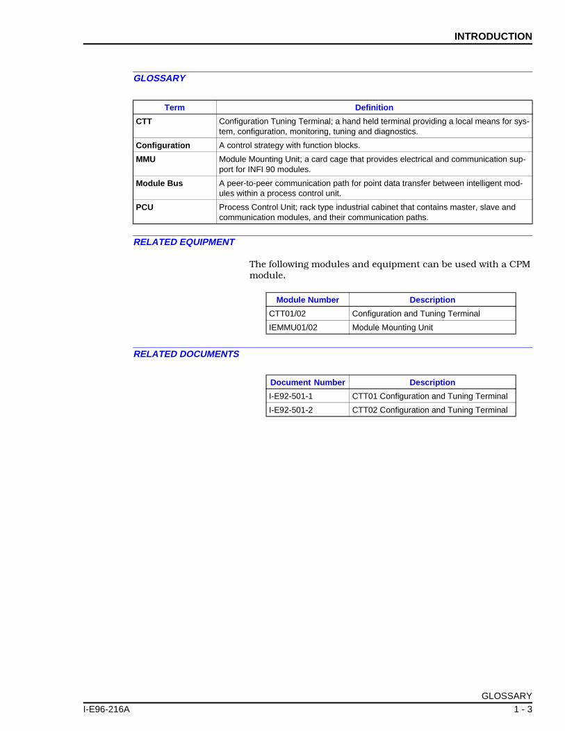
The following modules and equipment can be used with a CPMmodule.
RELATED DOCUMENTS
Term Definition
CTT Configuration Tuning Terminal; a hand held terminal providing a local means for sys-tem, configuration, monitoring, tuning and diagnostics.
Configuration A control strategy with function blocks.
MMU Module Mounting Unit; a card cage that provides electrical and communication sup-port for INFI 90 modules.
Module Bus A peer-to-peer communication path for point data transfer between intelligent mod-ules within a process control unit.
PCU Process Control Unit; rack type industrial cabinet that contains master, slave and communication modules, and their communication paths.
Module Number Description
CTT01/02 Configuration and Tuning Terminal
IEMMU01/02 Module Mounting Unit
Document Number Description
I-E92-501-1 CTT01 Configuration and Tuning Terminal
I-E92-501-2 CTT02 Configuration and Tuning Terminal
GLOSSARY
1 - 3
INTRODUCTION ®
SPECIFICATIONS
® Littlefuse is a registered trademark of Tracor Incorporated.™ Bussman is a trademark of Bussman, Division of Cooper Industries.
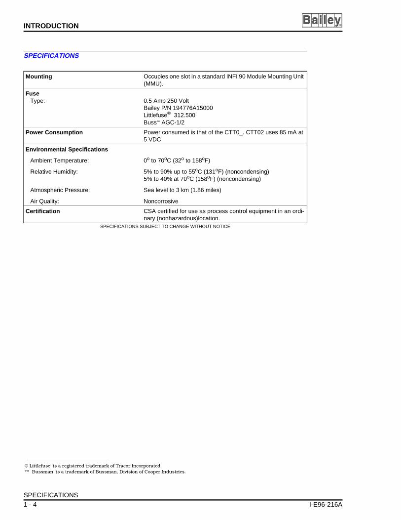
Mounting Occupies one slot in a standard INFI 90 Module Mounting Unit (MMU).
FuseType: 0.5 Amp 250 Volt
Bailey P/N 194776A15000Littlefuse® 312.500Buss™ AGC-1/2
Power Consumption Power consumed is that of the CTT0_. CTT02 uses 85 mA at 5 VDC
Environmental Specifications
Ambient Temperature:
Relative Humidity:
Atmospheric Pressure:
Air Quality:
0o to 70oC (32o to 158oF)
5% to 90% up to 55oC (131oF) (noncondensing)5% to 40% at 70oC (158oF) (noncondensing)
Sea level to 3 km (1.86 miles)
Noncorrosive
Certification CSA certified for use as process control equipment in an ordi-nary (nonhazardous)location.
SPECIFICATIONS SUBJECT TO CHANGE WITHOUT NOTICE
SPECIFICATIONS
1 - 4 I-E96-216A
SECTION 2 - DESCRIPTION AND OPERATION
I-E96-216A
INTRODUCTION
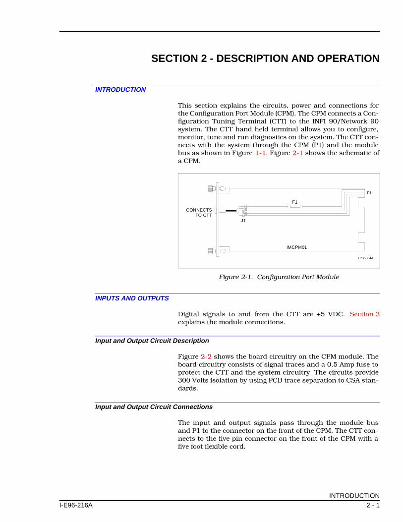
This section explains the circuits, power and connections forthe Configuration Port Module (CPM). The CPM connects a Con-figuration Tuning Terminal (CTT) to the INFI 90/Network 90system. The CTT hand held terminal allows you to configure,monitor, tune and run diagnostics on the system. The CTT con-nects with the system through the CPM (P1) and the modulebus as shown in Figure 1-1. Figure 2-1 shows the schematic ofa CPM.
INPUTS AND OUTPUTS
Digital signals to and from the CTT are +5 VDC. Section 3explains the module connections.
Input and Output Circuit Description
Figure 2-2 shows the board circuitry on the CPM module. Theboard circuitry consists of signal traces and a 0.5 Amp fuse toprotect the CTT and the system circuitry. The circuits provide300 Volts isolation by using PCB trace separation to CSA stan-dards.
Input and Output Circuit Connections
The input and output signals pass through the module busand P1 to the connector on the front of the CPM. The CTT con-nects to the five pin connector on the front of the CPM with afive foot flexible cord.
Figure 2-1. Configuration Port Module
TP35834A
P1
IMCPM01
CONNECTSTO CTT
J1
F112345
INTRODUCTION
2 - 1

DESCRIPTION AND OPERATION ®
LOGIC POWER
Logic power (+5 VDC) for the CTT circuits connects through thetop 12-pin card edge connector (P1) shown in Figure 2-1.
MODULE BUS
The module bus provides a 83.3 kilobaud peer-to-peer commu-nication link capable of supporting up to 32 drops.
Figure 2-2. IMCPM01 Input/Output Circuit
23
514
CTT CONNECTORMOUNTED ON
FACEPLATE
MODULE BUS(MMU BACKPLANE)
TP35832A
J1F1 P1
RED 1 1-2WHT 2 5-60.5 A, 250 V
WHT 3
BLK 4 9BRN 5 11
LOGIC POWER
2 - 2 I-E96-216A

SECTION 3 - INSTALLATION
I-E96-216A
INTRODUCTION
This section explains what you must do before you put theConfiguration Port Module (IMCPM01) into operation. DO NOTPROCEED with operation until you read, understand and dothe steps in the order in which they appear. Refer to the Con-figuration and Tuning Terminal Product Instruction Manualfor more details about the CTT.
UNPACKING AND HANDLING
Special Handling
The CPM does not use electrostatic sensitive devices. No spe-cial handling is required.
General Handling
1. Examine the hardware when you receive it to verify that ithas not been damaged in transit.
2. Notify the nearest Bailey Controls Sales Office of any ship-ping or handling damage.
3. File a claim for any damage with the company that handledthe shipment.
4. Use the original packing and container to store the hard-ware.
5. Store the hardware in clean air that is free from tempera-ture and moisture extremes.
SETUP AND INSTALLATION
Before installing, check to see that the fuse on the board isgood. There are no jumpers or switches to set on the CPM.
Physical Installation
The CPM module inserts into a standard INFI 90 ModuleMounting Unit (MMU) and occupies one slot. To install:
1. Align the module with the guide rails in the MMU. Gentlyslide the module in until the front panel is flush with the topand bottom of the MMU frame.
INTRODUCTION
3 - 1
INSTALLATION ®
2. Lock the module in place by turning the two captive screwson faceplate one-half turn. The module is in place when thenotch on each screw is vertical and the open end is pointingtoward the center of the module.
3. Connect the CTT cable to the connector on the front of theCPM. Check the cable to see that it is seated.
4. If the CTT does not power up refer to Section 4.
NOTE: A CPM module can be removed or installed without power-ing down the system.
WIRING CONNECTIONS AND CABLING
The CPM has one card edge connector (P1) to supply logicpower and provide digital communications. It has a five pinconnector on the faceplate to connect the CTT.
Wiring
Installing the module in the MMU connects the CPM to the +5VDC logic power at P1. The +5 VDC is necessary to drive theCTT circuitry. It also connects P1 to the module bus/control-way for communication with the master modules. The P1 con-nection requires no additional wiring or cabling.
Cable Connections
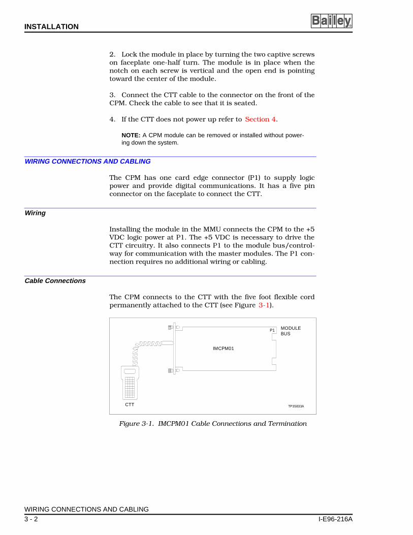
The CPM connects to the CTT with the five foot flexible cordpermanently attached to the CTT (see Figure 3-1).
Figure 3-1. IMCPM01 Cable Connections and Termination
CTT TP35833A
P1
IMCPM01
MODULEBUS
WIRING CONNECTIONS AND CABLING
3 - 2 I-E96-216A

INSTALLATION
I-E96-216A
FUSING
The CPM has a 0.5 Amp on-board fuse. Use only a 0.5 Amp250 Volt fuse Bailey P/N 194776A15000, Littlefuse P/N312.500, Bussman AGC-1/2 or equivalent.
PRE-OPERATING ADJUSTMENTS
You do not have to make any adjustments to the CPM beforeoperating.
FUSING
3 - 3

SECTION 4 - TROUBLESHOOTING
I-E96-216A
INTRODUCTION
This section explains the error indications and correctiveactions for the Configuration Port Module (IMCPM01).
ERROR INDICATIONS AND CORRECTIVE ACTION
The CTT01/02 receives power from module mounting unit. Ifthe CTT loses power, follow the steps in this section. There areno active electrical components on the CPM. The only replace-able part is the 0.5 Amp 250 Volt fuse.
MODULE REPLACEMENT
NOTE: You can remove the CPM module while system power issupplied.
1. Remove the CTT cable from the connector in the CPM face-plate.
NOTE: When removing the CTT cable pull on the plug, not on thecable.
2. Lock the module by turning the two captive screws on face-plate one-half turn. The module is unlocked when the notch oneach screw is vertical and the open end is pointing away fromthe center of the module.
3. Gently slide the module out of the module mounting unit.
4. Test the fuse to see if it is open. If the fuse is open continuewith Step 5. If the fuse is good continue with Step 6.
5. If the fuse is open, remove it from the fuse holder (see Fig-ure 4-1). Install a new fuse, use only a 0.5 Amp, 250 Volt fuse(Bailey Controls P/N 194776A15000).
6. Connect the CTT cable to the connector on the front of theCPM. Check the cable to see that it is seated.
7. Insert the module into the module mounting unit. Refer toSection 3 for the procedures to install a module.
8. If the CTT does not power up, it needs to be checked. Referto the CTT Product Instruction for troubleshooting and repairinformation.
NOTE: If the CPM is faulty, replace it with a new one.
INTRODUCTION
4 - 1

TROUBLESHOOTING ®
MODULE PIN CONNECTIONS
The CPM module has one connection point for external signalsand power (P1). Table 4-1 shows the P1 pin connections.
Figure 4-1. IMCPM01 Fuse Location
TP35834A
P1
IMCPM01
CONNECTSTO CTT
J1
F112345
Table 4-1. P1 Pin Connections
Pin Connection Pin Connection
1 +5 VDC 7 NC1
2 +5 VDC 8 NC1
3 NC1 9 Power Fail Interrupt
4 NC1 10 NC1
5 Common 11 Module Bus
6 Common 12 NC1
1. Not Connected.
MODULE PIN CONNECTIONS
4 - 2 I-E96-216A
SECTION 5 - MAINTENANCE
I-E96-216A
INTRODUCTION
The Configuration Port Module (IMCPM01) requires limitedmaintenance. This section contains a schedule to maintain theCPM.
MAINTENANCE SCHEDULE
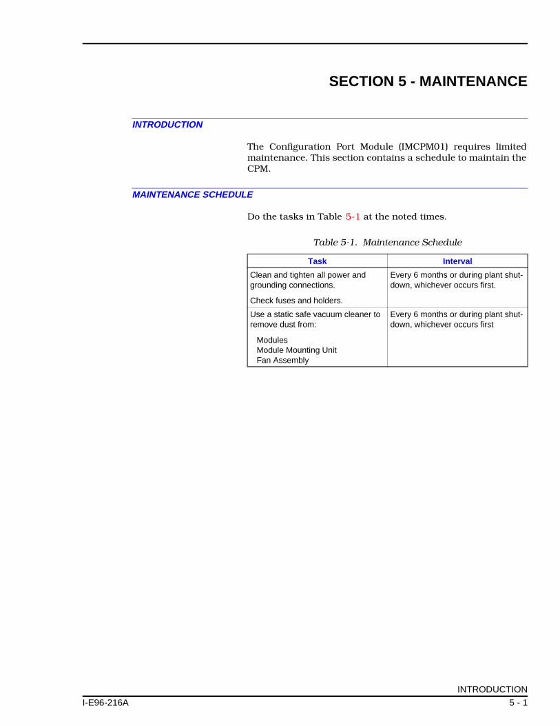
Do the tasks in Table 5-1 at the noted times.
Table 5-1. Maintenance Schedule
Task Interval
Clean and tighten all power and grounding connections.
Check fuses and holders.
Every 6 months or during plant shut-down, whichever occurs first.
Use a static safe vacuum cleaner to remove dust from:
ModulesModule Mounting UnitFan Assembly
Every 6 months or during plant shut-down, whichever occurs first
INTRODUCTION
5 - 1
SECTION 6 - SUPPORT SERVICES
I-E96-216A
INTRODUCTION
Bailey Controls is ready to help in the use and repair of itsproducts. Contact your nearest sales office to make requestsfor sales, repair and maintenance contracts.
REPLACEMENT PARTS AND ORDERING INFORMATION
When making repairs at your plant, order parts from a BaileyControls sales office. Please provide this information:
1. Part description, part number and quantity.
2. Model and serial numbers (if used).
3. Bailey Controls manual number, page number and figurethat shows the part.
When you order standard parts from Bailey Controls, use partnumbers and descriptions from the Spare Parts Lists. Youmust order parts without descriptions from the nearest BaileyControls sales office.
TRAINING
Bailey Controls has a modern training center that provides ser-vice and repair classes. We can provide in-plant training ofyour personnel. Contact a Bailey Controls sales office for spe-cific information and scheduling.
TECHNICAL DOCUMENTATION
You can obtain additional copies of this manual from the near-est Bailey sales office at a reasonable charge.
INTRODUCTION
6 - 1

Visit Elsag Bailey on the World Wide Web at http://www.bailey.com
Our worldwide staff of professionals is ready to meet your needs for process automation. For the location nearest you, please contact the appropriate regional office.
AMERICAS29801 Euclid AvenueWickliffe, Ohio USA 44092Telephone 1-216-585-8500Telefax 1-216-585-8756
ASIA/PACIFIC152 Beach RoadGateway East #20-04Singapore 189721Telephone 65-391-0800Telefax 65-292-9011
EUROPE, AFRICA, MIDDLE EASTVia Puccini 216154 Genoa, ItalyTelephone 39-10-6582-943Telefax 39-10-6582-941
GERMANYGraefstrasse 97D-60487 Frankfurt MainGermanyTelephone 49-69-799-0Telefax 49-69-799-2406
Form I-E96-216A Litho in U.S.A. 1290Copyright © 1990 by Elsag Bailey Process Automation, As An Unpublished Work® Registered Trademark of Elsag Bailey Process Automation™ Trademark of Elsag Bailey Process Automation