E30 Rear Foglight Installation -...
16
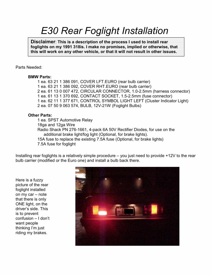
E30 Rear Foglight Installation Parts Needed: BMW Parts: 1 ea. 63 21 1 386 091, COVER LFT.EURO (rear bulb carrier) 1 ea. 63 21 1 386 092, COVER RHT.EURO (rear bulb carrier) 2 ea. 61 13 0 007 472, CIRCULAR CONNECTOR, 1.0-2.5mm (harness connector) 1 ea. 61 13 1 370 692, CONTACT SOCKET, 1.5-2.5mm (fuse connector) 1 ea. 62 11 1 377 671, CONTROL SYMBOL LIGHT LEFT (Cluster Indicator Light) 2 ea. 07 50 9 063 574, BULB, 12V-21W (Foglight Bulbs) Other Parts: 1 ea. SPST Automotive Relay 18ga and 12ga Wire Radio Shack PN 276-1661, 4-pack 6A 50V Rectifier Diodes, for use on the additional brake light/fog light (Optional, for brake lights). 15A fuse to replace the existing 7.5A fuse (Optional, for brake lights) 7.5A fuse for foglight Installing rear foglights is a relatively simple procedure – you just need to provide +12V to the rear bulb carrier (modified or the Euro one) and install a bulb back there. Here is a fuzzy picture of the rear foglight installed on my car – note that there is only ONE light, on the driver’s side. This is to prevent confusion – I don’t want people thinking I’m just riding my brakes. Disclaimer: This is a description of the process I used to install rear foglights on my 1991 318is. I make no promises, implied or otherwise, that this will work on any other vehicle, or that it will not result in other issues.
-
Upload
trinhtuyen -
Category
Documents
-
view
251 -
download
2
Transcript of E30 Rear Foglight Installation -...
E30 Rear Foglight Installation Parts Needed: BMW Parts:
1 ea. 63 21 1 386 091, COVER LFT.EURO (rear bulb carrier) 1 ea. 63 21 1 386 092, COVER RHT.EURO (rear bulb carrier) 2 ea. 61 13 0 007 472, CIRCULAR CONNECTOR, 1.0-2.5mm (harness connector) 1 ea. 61 13 1 370 692, CONTACT SOCKET, 1.5-2.5mm (fuse connector) 1 ea. 62 11 1 377 671, CONTROL SYMBOL LIGHT LEFT (Cluster Indicator Light) 2 ea. 07 50 9 063 574, BULB, 12V-21W (Foglight Bulbs)
Other Parts:
1 ea. SPST Automotive Relay 18ga and 12ga Wire Radio Shack PN 276-1661, 4-pack 6A 50V Rectifier Diodes, for use on the
additional brake light/fog light (Optional, for brake lights). 15A fuse to replace the existing 7.5A fuse (Optional, for brake lights) 7.5A fuse for foglight
Installing rear foglights is a relatively simple procedure – you just need to provide +12V to the rear bulb carrier (modified or the Euro one) and install a bulb back there.
Here is a fuzzy picture of the rear foglight installed on my car – note that there is only ONE light, on the driver’s side. This is to prevent confusion – I don’t want people thinking I’m just riding my brakes.
Disclaimer: This is a description of the process I used to install rear
foglights on my 1991 318is. I make no promises, implied or otherwise, that this will work on any other vehicle, or that it will not result in other issues.

Here is a picture of the rear of the car with the brakes on – notice I now have two additional lights when I step on the brakes – I added the inboard lights when I added the foglight.
You can either wire the foglight up to just be a foglight, or you can set it up to be both a foglight and additional brake lights. Again, without getting into many details, the recommended procedure is to wire a SINGLE bulb up for the rear foglight, on the driver’s side. For the complete story, see http://dmses.dot.gov/docimages/pdf82/176157_web.pdf.
Obviously, you will be making changes to your car’s electrical system. If you aren’t comfortable doing this, find someone who is, or don’t do it! The risk of either damaging
something or burning your car down is relatively small, but it is there.
The basic procedure is that you install a switch on the dash that controls when the rear foglight is on. This will involve adding some wiring, adding the switch, and possibly replacing some parts. You can also hook the rear foglight up so that it only comes on when the front foglights are on, if you so choose, but I did not do that and won’t provide any details about that here. I’ll be covering how to set up the lights so that you have both additional brake lights and a single rear foglight bulb.
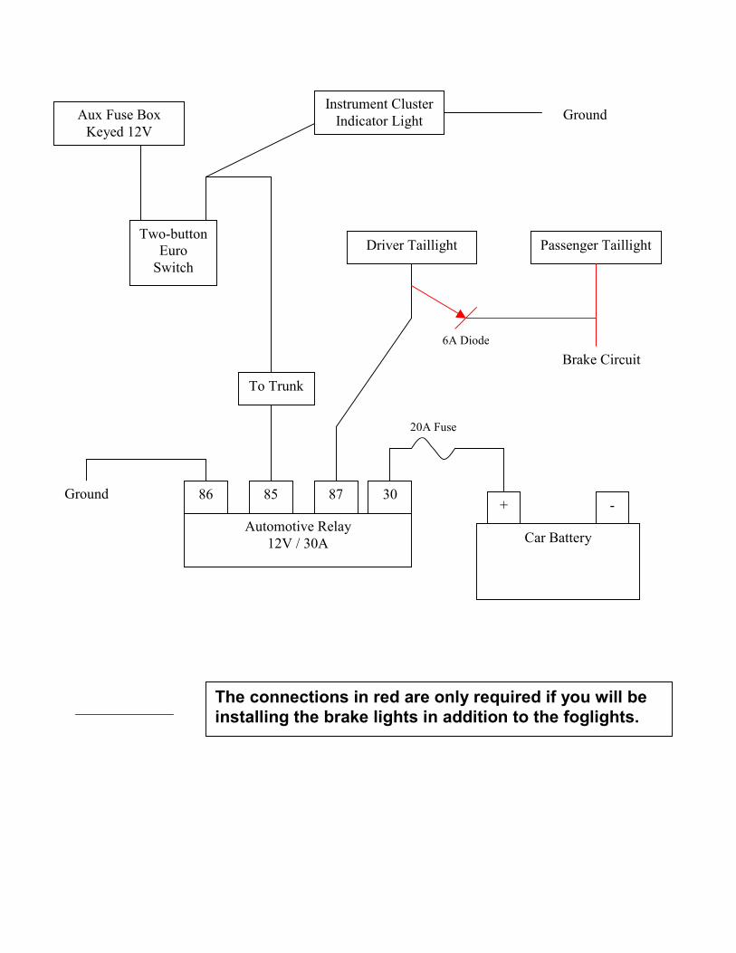
The last page has a simple circuit diagram. It’s not pretty, but it works. Review the diagram as you go, and confirm wire colors and circuits with the appropriate schematic for YOUR VEHICLE before you cut into any wiring. Just because it’s a green wire with a red stripe in my car doesn’t mean it necessarily is in your car. Verify your schematic by following the actual wires on your car – it pays to be cautious here.
Disconnect the battery before performing any modifications to the electrical system!
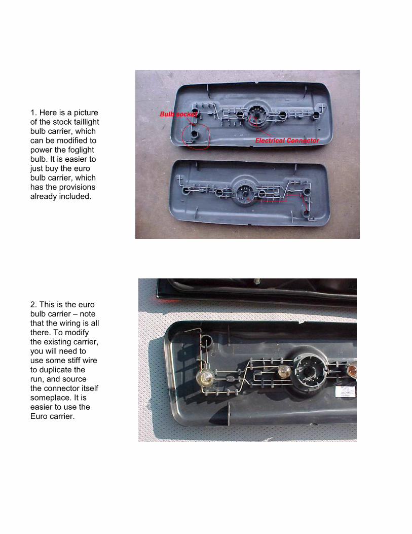
1. Here is a picture of the stock taillight bulb carrier, which can be modified to power the foglight bulb. It is easier to just buy the euro bulb carrier, which has the provisions already included.
2. This is the euro bulb carrier – note that the wiring is all there. To modify the existing carrier, you will need to use some stiff wire to duplicate the run, and source the connector itself someplace. It is easier to use the Euro carrier.

3. First, knock out the blank where the foglight bulb will go. I used an X-acto knife to carefully scribe around the hole, then knocked the plug into the taillight housing and fished it out. In this picture, the blank came from the bottom hole on the left side.
4. Next, you will need to either modify your bulb carrier, or throw it out and get out the spanking new euro one. Swap your bulbs over to the new carrier and install your new foglight/brakelight bulb.
5. On to the wiring. Starting from the front of the car, pop the cap off of the auxiliary fuse block, located next to the fuses under the hood. It’s the small one with the black cap, and should be clipped to the inboard side of the fuse box.

6. Here is the auxiliary block with the cap off and a fuse in place. You should find that there are two wires already run to this block – one is constant +12V, hot all the time, the other is keyed +12V, hot only when the key is in run or start. You want this one, unless you want to run your battery down if you forget to turn the light off.
Alternatively, you can pull +12V from somewhere under the dash, if you don’t want to run wires through the firewall.
7. Feed an 18ga wire up through the rubber boot (if you have it) on the bottom of the auxiliary fuse block, then crimp connector 61 13 1 370 692 (#19 here) to the end of the wire. Push the connector up into the auxiliary fuse block body from behind – it will snap into place, and you now have a place to put a fuse. I used a 7.5A fuse, probably overkill, since this is only providing a control current, but it works. Feed the wire through the firewall to the driver’s side footwell.

8. Run the wire to your switch. I used a euro two-button switch (#4 here), to maintain the stock appearance inside the car. You don’t really need to do this, but the euro switch isn’t really that much more expensive than a regular toggle switch, so you may as well use it.
The euro switch has four terminals on the back – one pair for the front lights and one pair for the rear lights. I was unable to source the correct connector body to just plug into the back of euro switch, so I soldered female spade connectors to both sets of wires (front and rear, two each), covered them in heat shrink tubing, and plugged them directly onto the switch terminals. For the front foglight wires, I soldered male spade connectors to the other end of a pair of wires and inserted them into the existing foglight connector body. See the rough diagram below.

9. It doesn’t matter which side of the switch you go to – either terminal will work. Run a wire out from the other terminal on the switch – this will be your lead to the rear of the car and to the indicator light, if so desired.
If you don’t want a dash indicator light, skip to step 21.
10. If you do want an indicator light on the cluster, you will need to do some more wiring – there doesn’t seem to be any wiring provision in the US models for an indicator light on the dash for the rear foglights, just as there is no provision for the harness. The instrument cluster circuit board, however, does appear to support the rear foglight indicator.

11. In order to have the correct symbol on the cluster, you’ll have to remove the instrument cluster and replace the indicator panel on the left side of the cluster, which also contains the CHECK ENGINE graphic. When I made the change over, I lost my CHECK ENGINE, replaced by a solid green block. No great loss.
12. Remove the cluster (carefully!) and place it face up on your workbench. I won’t provide details on removing the cluster – check your Bentley for the appropriate instructions. If you have an airbag-equipped vehicle, you MUST take the necessary precautions to ensure the airbag does not deploy! Don’t take any shortcuts here.
13. I don’t have any pictures of that portion of the install, but it is pretty straightforward. Slide the existing plastic lens piece out and slide the new one in, PN 62 11 1 377 671, number 12 in this picture.

14. There are two ways to wire a light bulb behind that display panel you just installed: what I did, and what I suspect is the correct way. Following the circuits on the printed circuit board indicates to me that you may be able to light a warning light bulb when you turn on the rear foglight by adding one terminal to the instrument cluster connector and running it off of the switch. Alternatively, you can do what I did, and add a pigtailed bulb into the socket on the back of the cluster, disregarding the existing circuitry.
15. If you go the pigtail route, you MUST MAKE CERTAIN that every time you put the bulb in, you have it oriented the correct way – GROUND ON TOP. If you accidentally put the bulb in with the ground lead on the bottom, you will cook your PCB, or at least part of it. Read on.
16. Flip the cluster over – put it on a towel, so you don’t scratch the irreplaceable face. On the backside of the cluster, you’ll see where the bulb is supposed to go. In the picture to the right, I have installed the pigtailed light detailed below.
17. One side of the cluster connector is ground, one is 12V – if you are going to install the pigtailed indicator lamp as I did, you need to make sure that the lead that goes to ground is facing the TOP of the instrument cluster, as indicated here.

18. You can see the trace I burned out when I put the bulb in wrong. I believe that you can use the existing PCB to power the rear foglight indicator light, but I haven’t tried it yet – so be careful! Look at the trace of red, blue, and green dots – they follow the circuits on the PCB. The red dots are, I believe, the trace that will allow you to run the rear foglight indicator without pigtailing the light.
19. According to the way the trace goes on the PCB, I believe that if you supply 12V to the connector shown in this picture, it should light the rear foglight indicator. As I said, I haven’t tested this.
20. To make the pigtailed bulb I used, solder the wire from the switch to one side of the 3W indicator bulb, and then solder another wire to the other side to go to ground. Here is the modified bulb on top, original bulb on bottom. Again, make sure you put the ground wire on the TOP if you do this!

21. I split the wire coming from the switch, and ran one end to the pigtail/indicator light as shown, and the other end to the trunk. I crossed over to the passenger side under the rear seat, and then followed the existing battery cable into the trunk itself.
22. Once in the trunk, I installed a relay on the fuel door popper bracket and ran my control wire to it. This went to terminal 85. Terminal 86 goes to ground, terminal 87 gets the lead to the foglight, and terminal 30 gets the fused lead from the battery. I used 12ga wire here, again probably overkill, but bigger is better!
23. Run the wire from terminal 87 to the driver’s side taillight, along the same path as the existing wiring harness (back wall of trunk, behind trim panel). Remove the connector body from the taillight housing by squeezing the clips together and pulling it out.

24. Looking at the connector body here, the hole at the “5 o’clock” position corresponds to slot 6, as numbered across the bottom of the connector body. Connector 61 13 0 007 472 has the correct terminal and snaps into the connector body, the green/black wire in the picture.
25. This connector has about 8” or so of wire leading to it. This terminal will snap right in to the housing – make sure that it is properly aligned when you snap it in, you apparently need a special tool to remove it once it is in. If you will only be using your foglight bulb as a foglight, you are about done – solder the green/black wire to the wire leading from terminal 87, snap the terminal into the harness connector, install the bulb carrier, and fire it up. You should have a foglight on the back now.
If you are installing only the rear foglight, you are done! Congratulations, you are now more visible from the rear in the fog and rain!
26. If you are going to do what I did, which is to use these bulbs as both a rear foglight AND additional brake lights, there is more work to be done – namely, you have to isolate the foglight circuit from the brake light circuit, and tap into the brake light circuit on both sides.

27. To add the brake light function, you’ll be tapping in to the existing brake light wiring. Slice the insulation off of the green wire with the red stripe on the passenger side harness that leads to the taillight connector. Solder one end of the wire on connector 61 13 0 007 472 in to this wire, then wrap it back up with electrical tape. If you are going to buck conventional wisdom and advice and install foglights on both sides, you’ll need blocking diodes on each light, as below.
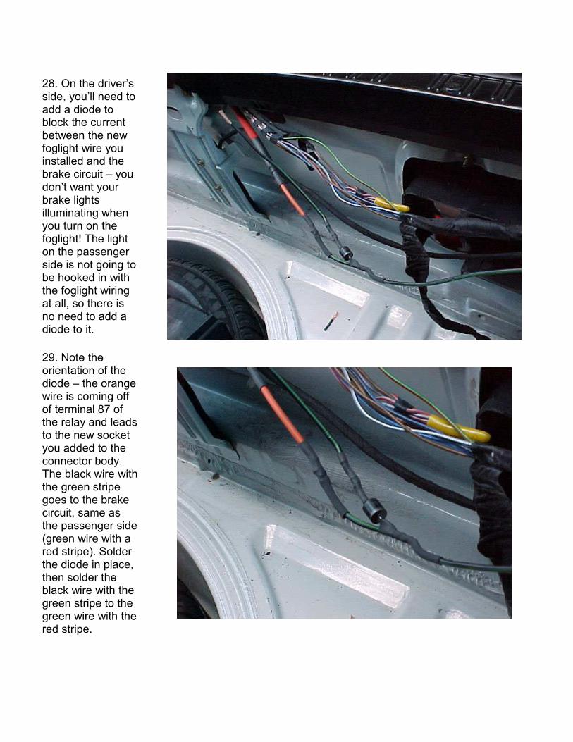
28. On the driver’s side, you’ll need to add a diode to block the current between the new foglight wire you installed and the brake circuit – you don’t want your brake lights illuminating when you turn on the foglight! The light on the passenger side is not going to be hooked in with the foglight wiring at all, so there is no need to add a diode to it.
29. Note the orientation of the diode – the orange wire is coming off of terminal 87 of the relay and leads to the new socket you added to the connector body. The black wire with the green stripe goes to the brake circuit, same as the passenger side (green wire with a red stripe). Solder the diode in place, then solder the black wire with the green stripe to the green wire with the red stripe.

30. Remove the existing 7.5A fuse for the rear brake lights (should be fuse number 6) and replace it with a 15A fuse – remember, by adding two more stop lamp bulbs, you’ve doubled the number of lights that come on when you hit the brakes (not counting the CHMSL). The wiring should be more than capable of handling the load on the circuit. It is your car, though, not mine, so make sure that you are comfortable with the wiring handling the extra load. If not, fix it – I assume no liability if your car turns into a Pinto when you step on the brakes. Having said that, I’ve been driving mine for more than a year with no signs of problems.
31. You should be done – make sure that you have completed all of the connections, install the bulb carriers, hook the battery back up, and give it a shot. You should have two extra brakelights, and a rear foglight. Congratulations! Button it all back up and wait for a foggy morning!
Questions, comments, etc. can be sent to me at the following email address: [email protected].
Good luck!
John in MD – 1991 318is on Roadfly.com AK96SS on Bimmerforums.com AK96SS on M42Club.com
Aux Fuse Box
Keyed 12V
Two-button
Euro
Switch
To Trunk
Instrument Cluster
Indicator Light Ground
Automotive Relay
12V / 30A
85 86 Ground 87 30
Car Battery
+ -
Driver Taillight Passenger Taillight
20A Fuse
6A Diode
Brake Circuit
The connections in red are only required if you will be
installing the brake lights in addition to the foglights.