
E27 Gearless - Leroy-Somer · These symbols appear in this document whenever it is important to...
76
E27 Gearless Installation & maintenance Permanent magnet synchronous motor for lifts Part number: 5323 en - 2017.08 / b
Transcript of E27 Gearless - Leroy-Somer · These symbols appear in this document whenever it is important to...

E27 Gearless
Installation & maintenance
Permanent magnetsynchronous motor for lifts
Part number: 5323 en - 2017.08 / b

2
E27 Gearless - Installation and maintenance 5323 - 2017.08 / b
These symbols appear in this document whenever it is important to take special precautions during installation, operation, maintenance or servicing of the motors.
It is essential that electric motors are installed by experienced, qualified and authorized personnel.
In accordance with the main requirements of EEC Directives, the safety of people, animals and property should be ensured when fitting the motors into machines.
Particular attention must be given to equipotential ground or earthing connections.
The following preliminary precautions must be taken before working on any stationary device:• Mains voltage disconnected and no residual voltage present• Careful examination of the causes of the stoppage(jammed transmission - loss of phase - cut-out due to thermal protection, etc)
Even when not supplied with power, there is voltage at the terminals of a rotating synchronous motor with magnets.Accordingly, before carrying out any work check carefully that the motor is not rotating.
The short-circuiting of the phases is not allowed to manage the rescue operation of the lift.
For dismantling the E27 motor only
Assembly or maintenance of the rotor must not be carried out by people with pacemakers or any other implanted medical electronic device.
The motor rotor contains a powerful magnetic field. When the rotor is separated from the motor, its field may affect pacemakers or disturb digital devices such as watches, mobile phones, etc.
IMPORTANT

3
E27 Gearless - Installation and maintenance 5323 - 2017.08 / b
Dear Customer,
You have just acquired a Leroy-Somer Gearless motor.
This motor benefits from the experience of one of the largest manufacturers in the world, using state-of-the-art technology in automation, specially selected materials and rigorous quality control. As a result, the regulatory authorities have awarded our motor factories the ISO 9001, Edition 2008 international certificate.
We thank you for making this choice, and would ask you to read the contents of this manual.
By observing a few essential rules, you will ensure problem-free operation for many years.
Moteurs Leroy-Somer
NOTE:Leroy-Somer reserves the right to modify the characteristics of its products at any time in order to incorporate the latest technological developments. The information contained in this document may therefore be changed without notice.Copyright 2015: Moteurs Leroy-SomerThis document is the property of Moteurs Leroy-Somer.It may not be reproduced in any form without prior authorization.All brands and models have been registered and patents applied for.
INTRODUCTION


5
E27 Gearless - Installation and maintenance 5323 - 2017.08 / b
CONTENTS
1 - RECEIPT & IDENTIFICATION ............................................................................................................................. 6
2 - ENVIRONMENT ................................................................................................................................................... 6
3 - STORAGE ............................................................................................................................................................ 6
3.1 - Storage conditions ....................................................................................................................................... 6
3.2 - Prolonged storage (> 3 months) ................................................................................................................... 6
4 - INSTALLATION .................................................................................................................................................... 7
4.1 - Before installation ........................................................................................................................................ 7
4.2 - General recommendation ............................................................................................................................ 7
4.3 - Mechanical installation ................................................................................................................................. 7
4.3.1 - Lifting the motor ..................................................................................................................................................... 7
4.3.2 - Installing the motor ................................................................................................................................................ 8
4.3.3 - Traction ropes ....................................................................................................................................................... 8
4.3.4 - Ropes guard ......................................................................................................................................................... 9
4.4 - Electrical connection using the cables supplied by Leroy-Somer ................................................................. 9
4.4.1 - Wiring the motor, the thermal sensor and the encoder .......................................................................................... 9
4.4.2 - Wiring the brakes................................................................................................................................................. 10
4.4.3 - Earth connection ................................................................................................................................................. 10
4.5 - Details of the wire for the connection of the cables to the electrical cabinet ................................................ 11
4.6 - Electrical connection using your own cables .............................................................................................. 12
4.6.1 - Reference of the connectors and contacts........................................................................................................... 12
4.6.2 - Recommendation ................................................................................................................................................ 13
4.7 - Switching status of the microswitches ........................................................................................................ 13
5 - SHORT-CIRCUITING OF THE PHASES ........................................................................................................... 13
6 - COMMISSIONING .............................................................................................................................................. 13
7 - MAINTENANCE ................................................................................................................................................. 13
7.1 - Bearings .................................................................................................................................................... 13
7.2 - After one month’s operation ....................................................................................................................... 13
7.3 - After an emergency stop ............................................................................................................................ 13
7.4 - Every year .................................................................................................................................................. 13
8 - APPENDIX 1....................................................................................................................................................... 13
8.1 - Failsafe brakes .......................................................................................................................................... 15
6
RECEIPT & IDENTIFICATION
E27 Gearless - Installation and maintenance 5323 - 2017.08 / b
To ensure that the Leroy-Somer Gearless E27 you have just purchased is entirely satisfactory, it is essential to adhere to the following instructions.
WARNING Contact with energized or rotating parts may cause injury.
WARNING Do not touch the housing of a motor during operation, as it can reach high temperatures.
Reminder: installation, servicing and maintenance must only be carried out by qualified personnel.Failure to follow the instructions in this document or to apply them correctly, releases the manufacturer from responsibility.The product is covered by the warranty as long as any partial or total dismantling has only been performed with the assistance of Leroy-Somer (or its approval).
WARNING Check that the lift car has been immobilized before performing any work on the motor or the brakes.
1 - RECEIPT & IDENTIFICATIONInspect the machine as soon as it is received. If there is any damage that has been caused during transportation, contact immediately the carrier.
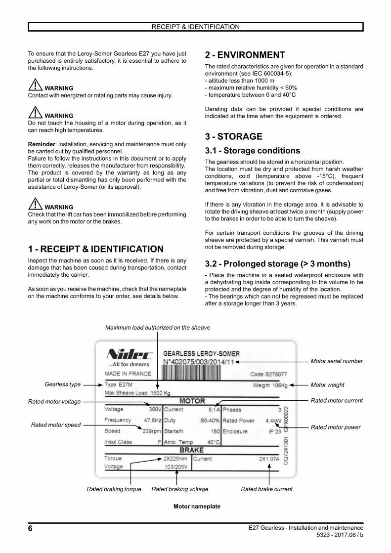
As soon as you receive the machine, check that the nameplate on the machine conforms to your order, see details below.
2 - ENVIRONMENTThe rated characteristics are given for operation in a standard environment (see IEC 600034-5):- altitude less than 1000 m- maximum relative humidity < 60%- temperature between 0 and 40°C
Derating data can be provided if special conditions are indicated at the time when the equipment is ordered.
3 - STORAGE3.1 - Storage conditionsThe gearless should be stored in a horizontal position.The location must be dry and protected from harsh weather conditions, cold (temperature above -15°C), frequent temperature variations (to prevent the risk of condensation) and free from vibration, dust and corrosive gases.
If there is any vibration in the storage area, it is advisable to rotate the driving sheave at least twice a month (supply power to the brakes in order to be able to turn the sheave).
For certain transport conditions the grooves of the driving sheave are protected by a special varnish. This varnish must not be removed during storage.
3.2 - Prolonged storage (> 3 months)- Place the machine in a sealed waterproof enclosure with a dehydrating bag inside corresponding to the volume to be protected and the degree of humidity of the location.- The bearings which can not be regreased must be replaced after a storage longer than 3 years.
Motor nameplate
Maximum load authorized on the sheave
Gearless type
Motor serial number
Motor weight
Rated motor currentRated motor voltage
Rated motor speed
Rated braking torque Rated braking voltage Rated brake current
Rated motor power

7
INSTALLATION
E27 Gearless - Installation and maintenance 5323 - 2017.08 / b
4 - INSTALLATION4.1 - Before installation
If the equipment has been stored for several months, it is essential to check the correct insulation between the phases and the earth terminal on the motor (minimum 100 MΩ at 500 V D.C. for 60 seconds) after having disconnected all the electronic circuits if necessary.
Do not apply the megohmmeter to the terminals of the thermal sensors as this may damage them.If the required value is not reached, dry the motor using internal or external heating.
Drying using external heating- Place the motor in an oven at 70°C for at least 24 hours until the correct insulation is obtained (100 MΩ).- Take care to increase the temperature gradually to clear the condensation.- After drying at ambient temperature during the cooling phase, check the insulation value regularly, as it will initially tend to fall, then rise.
Drying using internal heating (drawing 1)- Connect motor windings V1 and W1 in parallel in relation to U1.- Read off the resistance between U and V//W.- Apply a low voltage D.C. current to them (to obtain 10% of the rated current calculated using the winding resistances), then increase the voltage until 50% of the rated current is reached- Maintain the power for 4 hours. The temperature of the motor should increase slightly.
If the brakes are released, the sheave will move slightly on power-up (angular setting of the rotor in relation to the stator).
U1 Idc < 50% In
Udc
V1 W1
Drawing 1
Winding connectionsfor drying using
internal reheating
4.2 - General recommendationThe installation must comply with the motor characteristics indicated on the nameplate (see section 1).It must include electrical safety devices.Check that the handling equipment (slings, etc.) is suitable for the weight of the machine.Use the attachment points provided on the machine.Check that the cables are correctly positioned so that they are not damaged.Provide the necessary mechanical protection devices to prevent people working on the machine becoming caught or trapped by the sheave and/or the cables.During building works, we recommend to protect the brakes and micro-switches against dust (by wrapping them into a shrink film for example). If the site is permanently subject to dust, we recommend to fit the brakes cover available as an option.The motors must be installed in such a way that the cooling air (not too damp, dust-free, and containing no corrosive gases or vapors) circulates freely.For the ease of access to the encoder, we recommend to install the motor with a minimum distance of 200mm between the cast iron cover protecting the encoder and the wall of the elevator shaft.
4.3 - Mechanical installation4.3.1 - Lifting the motor
Pic. 3 : Lifting the motor (for illustration only)
Weight of the motor (kg)E27S E27M E27L
93 kg 106 kg 167 kg

8
INSTALLATION
E27 Gearless - Installation and maintenance 5323 - 2017.08 / b
4.3.2 - Installing the motorThe Gearless motor must be installed on a chassis that is not subject to vibration and must be secured using 4 M12 screws class 8.8.The permissible unevenness of the chassis is 1 mm.Due to the mechanical construction of the motor, this is mandatory to use the isolation pads supplied for the fixing of the motor onto the chassis (2 rectangular pads to be installed under the motor feet and 4 round pads to be installed under the chassis).
4 x Screw M12 x L (not supplied)2 x Top pads (LSY160-1-237)4 x Bottom pad (GIR130-1-47)
The mounting principle is as follows:
Gearless
Top pad
FrameBottom pad
Screw M12 x L (not supplied)
The chassis must be drilled as follows:
I I
150 ±0.5 (E27S/M)170 ±0.5 (E27L)
60 mini
240
min
i
31±0.3
175
±0.5
Common area1
Motor type W (mm)E27S 150 +/- 0,5E27M 150 +/- 0,5E27L 170 +/- 0,5
The fixing screws (not supplied) must be tightened once the traction ropes and the traction sheave are perfectly aligned and once the full load is applied onto the traction sheave. After contact of the screw’s head with the metallic washer, tighten of 1 turn with a tolerance of +¼ 0.For securing the fixing screws, use a thread locking glue (low or mid strength) applied onto the 10mm of the screw end or a mechanical seal on the screws heads (linking two screws).
Below are the recommended screw’s lengths depending on the thickness of the chassis:
Thickness of the chassis 6 to 8 mm 10 to 12 mm < or = 16
Screw length 50 or 55 mm 55 or 60 mm 60 or 65 mm
4.3.3 - Traction ropes
Check that the traction ropes are of correct type for the sheave of the motor. The rope pull must be vertical.If the number of grooves available on the traction sheave is higher than the number of ropes installed then the ropes must be centered on the sheave.
Positioning of the traction ropes
YES
NO
NO

9
INSTALLATION
E27 Gearless - Installation and maintenance 5323 - 2017.08 / b
The motor’s fixing screws must not be loaded with a shearing force.The direction of the force applied onto the traction sheave must be vertical and must be perpendicular to the motor feet. the force applied must compress the isolation pads.
4.3.4 - Ropes guard When the ropes have been installed, refit the ropes guard system. Use Loctite 242 (or equivalent) on the tap of each bolt and tighten at a torque of 15 N.m +/- 10%.
There is a high risk of jamming your fingers between the cables and the sheave.
Ropes guard
4.4 - Electrical connection using the cables supplied by Leroy-Somer
4.4.1 - Wiring the motor, the thermal sensor and the encoder
Remove the cover using a Torx screwdriver or key, reference TX 27.
When working on the encoder please follow the below recommendation:
Details of the connections
Motor power fast connector
Cover to remove to access to the encoder connector
Metal clampfor power cable grounding
Thermal sensor fast connector
Metal clamp for thermal sensor
cable grounding
NO
NO
NO
YES

10
INSTALLATION
E27 Gearless - Installation and maintenance 5323 - 2017.08 / b
Once the connections are done, refit: - the encoder protection cover using a flat screwdriver,- the main cover making sure that the electrical cables are
correctly positioned in the cover openings. Thightening torque : 8N.m.
4.4.2 - Wiring the brakesFor wiring the brakes, please refer to the nameplate applied onto the brakes and to the appendix 1 of this manual.
The grounding of the cable shielding is doneusing the metal clamps.
4.4.3 - Earth connection
Connect the earth using the dedicated terminals on both motor and brakes.
The grounding of the cable shielding is done
using the metal clamps
The encoder protection cover is refitted

11
INSTALLATION
E27 Gearless - Installation and maintenance 5323 - 2017.08 / b
4.5 - Details of the wire for the connection of the cables to the electrical cabinet
FOR ALL E27 TYPE
Motor side Connector Type of cable Electrical cabinet side
Black
Power cable
Black U1Brown Brown V1Blue Grey W1
Green/Yellow Green/Yellow Ground
Black Thermal sensor cable
BrownPTC
Black White
Encoder cable
1 Cos2 CosRef3 Sin4 SinRef5 Data6 Data\7 -8 -9 -10 -11 Clock out12 Clock out\13 +5V14 0V15 -
FOR E27S AND E27M (Intorq brakes)
Brakes side Connector Type of cable Electrical cabinet side
Grey PurpleMicroswitch
NCBlack Black
NODark Blue Red
Blue Blue Brake coilBlack Pink Brake coilGrey Brakes cable Grey
MicroswitchNC
Black YellowNO
Dark Blue GreenBlue Brown Brake coilBlack White Brake coil
FOR E27L (Mayr brakes)
Brakes side Connector Type of cable Electrical cabinet side
Grey PurpleMicroswitch
NCBlack Black
NOBlue Red
Brown Blue Brake coilDark blue Pink Brake coil
Grey Brakes cable GreyMicroswitch
NCBlack Yellow
NOBlue Green
Brown Brown Brake coilDark blue White Brake coil

12
INSTALLATION
E27 Gearless - Installation and maintenance 5323 - 2017.08 / b
4.6 - Electrical connection using your own cables4.6.1 - Reference of the connectors and contacts
Motor sideCustomer side
Connector Reference
Black U1 Connector: TECO ELECTRIC
1-480702-0 or equivalent
Contacts : MNL 926884-1
Brown V1
Blue W1
Green/Yellow Ground
Black
PTC
Connector: MOLEX ref.: 39-01-3028
Contacts : MOLEX série 5556 or TECO
ELECTRIC ref. : 0-350777-1
Black
2a Cos 2a Cos
5b CosRef 5b CosRef
4a Sin 4a Sin
3b SinRef 3b SinRef
6b Data 6b Data
1a Data\ 1a Data\
- -
- -
- -
- -
2b Clock out 2b Clock out
5a Clock out \ 5a Clock out \
1b +5V 1b +5V
4b 0V 4b 0V
- -
Brown Brakes coil
Wago ref. 231-205 / 037-000
Blue Brakes coil
Dark Blue
MicroswitchNO
BlackNC
Grey
Brown Brakes coil
Blue Brakes coil
Dark Blue
MicroswitchNO
BlackNC
Grey

13
SHORT-CIRCUITING OF THE PHASES
E27 Gearless - Installation and maintenance 5323 - 2017.08 / b
4.6.2 - RecommendationConnect the motor using cables of the correct cross-section
Nominal current per phase (A)
9.5 12 16
Min. cable cross-section (mm²)
1.5 1.5 2.5
The cable shielding must be connected to earth, see section 4.4.
It is the responsibility of the user to connect the motor in accordance with the current legislation and regulations in the country of use. This is particularly important as regards the size of the cables, the type and size of fuses, the earth or ground connection, powering down, acknowledging insulation faults and protection against overcurrents.
The table above is given for information only and must under no circumstances be used in place of the current standards.
The recommended cross-sections are given for a single-wire cable, with a maximum length of 10m. Above this, line drops due to the cable length must be taken into account.
4.7 - Switching status of the microswitches
Contact
Colors of the wiresBrake
releasedMicroswitch
closedConnector
fitted onto the brakes
Cables supplied by
Leroy-Somer
NC contact Black / Grey
Yellow/Grey YES NO
Black/Purple NO YES
NO contact
Black/ Dark Blue
Yellow/Green YES YES
Black/Red NO NO
5 - SHORT-CIRCUITING OF THE PHASESThe short-circuiting of the phases is not allowed to manage the rescue operation of the lift
6 - COMMISSIONINGCheck that the electrical equipment is correctly earthed before starting work.Before commissioning the machine, check that all the fixings and electrical connections are correctly tightened.During commissioning, check for noise and vibration and monitor the current and voltage on the machine while it is operating at rated load.
7 - MAINTENANCE7.1 - BearingsThe bearings do not require any maintenance as they are greased for life.
7.2 - After one month’s operation- Check that the screws and electrical connections are correctly tightened.- Check that there is no abnormal noise. Check the vibration. We recommend to stop the lift in case of tangible vibration and to control the complete installation.- Check the brakes airgap. Please refer to the appendix 1 of this manual.
7.3 - After an emergency stopCheck the brakes airgap. Please refer to the appendix 1 of this manual.
7.4 - Every yearSame as section 6.2.
8 - APPENDIX 18.1 - Failsafe brakes See following pages

Moteurs Leroy-SomerHeadquarter: Boulevard Marcellin Leroy - CS 10015
16915 ANGOULÊME Cedex 9
Limited company with capital of 65,800,512 €RCS Angoulême 338 567 258
www.leroy-somer.com

www.intorq.com
setting the standard
www.intorq.com
INTORQ BFK464Electromagnetically released spring-applied brake
Operating Instructions

INTORQ | BA 14.0197 | 06/2014 2
This documentation only applies to:
Product key
Not coded: Supply voltage, hub bore, options
BFK464-17S
BFK464-18S
BFK464-18S.2
BFK464-19S
BFK464-20S
BFK464-20S.1
BFK464-25S
BFK464-25S.1
BFK464-28S
INTORQ B FK -
AA
B
C
DD
E
Legend for the product key
INTORQ BFK464
Product group BrakesProduct type Spring-applied brakeType 464Size 17, 18, 19, 20, 25, 28Design S
S.1S.2
AA
B
C
D
E

INTORQ | BA 14.0197 | 06/2014 3
Identification
Document history
Packaging label Example
Manufacturer Bar codeType (see product key)
Type No.
Designation Qty. per boxRated/holding voltage Rated torque Packaging dateRated/holding power Hub diameterModel identificationNote CE mark
Name plate Example
Manufacturer Model identification CE markingType (see product key)DesignationRated/holding voltage Rated/holding power Hub diameterType No. Rated torque Date of manufacture
Material number Version Description
13348276 1.0 09/2010 TD09 First edition33000116 2.0 11/2010 TD09 Enlarged to include 19S and 28S sizes
Supplement of the tables in the Characteristics chapterSupplement of the important instructions in the Commissioning and operation chapter
33002148 3.0 08/2012 TD09 Supplement of the model identification number for the sizes 18S, 19S and 28SRevision of the operating timesSupplemented by versions 18S.2 and 25S.1Change of the phone and fax number as well as the cover page and back
33002149 4.0 06/2014 SC New construction FM, supplement of the size 17S
INTORQ | BA 14.0197 | 06/2014 4
Contents
1 Preface and general information........................................................................................................................... 51.1 About these Operating Instructions............................................................................................................... 51.2 Terminology used.......................................................................................................................................... 51.3 Conventions in use........................................................................................................................................ 51.4 Abbreviations used........................................................................................................................................ 61.5 Safety instructions and notices...................................................................................................................... 71.6 Scope of delivery........................................................................................................................................... 81.7 Disposal......................................................................................................................................................... 81.8 Drive systems................................................................................................................................................ 91.9 Legal regulations........................................................................................................................................... 9
2 Safety instructions ............................................................................................................................................... 102.1 General safety instructions.......................................................................................................................... 102.2 Application as directed ................................................................................................................................ 11
3 Technical specifications ...................................................................................................................................... 123.1 Product description...................................................................................................................................... 123.2 Rated data................................................................................................................................................... 153.3 Rating (design data) .................................................................................................................................... 173.4 Switching energy / operating frequency ...................................................................................................... 183.5 Emissions.................................................................................................................................................... 19
4 Mechanical installation ........................................................................................................................................ 204.1 Important notes ........................................................................................................................................... 204.2 Necessary tools........................................................................................................................................... 204.3 Assembly..................................................................................................................................................... 214.4 Installation procedure.................................................................................................................................. 22
5 Electrical installation............................................................................................................................................ 305.1 Electrical connection ................................................................................................................................... 305.2 Bridge/half-wave rectifiers (optional) ........................................................................................................... 315.3 Electrical connection ................................................................................................................................... 34
6 Commissioning and operation............................................................................................................................ 356.1 Important notes ........................................................................................................................................... 356.2 Function checks before commissioning ...................................................................................................... 356.3 Commissioning............................................................................................................................................ 376.4 During operation.......................................................................................................................................... 38
7 Maintenance and repair ...................................................................................................................................... 397.1 Wear of spring-applied brakes .................................................................................................................... 397.2 Inspections .................................................................................................................................................. 407.3 Maintenance................................................................................................................................................ 417.4 Spare-parts list ............................................................................................................................................ 437.5 Ordering spare parts ................................................................................................................................... 44
8 Troubleshooting and fault elimination ............................................................................................................... 45

Preface and general information
INTORQ | BA 14.0197 | 06/2014 5
1 Preface and general information
1.1 About these Operating Instructions
❚ These Operating Instructions will help you to work safely with the spring-applied brake with electromag-netic release. They contain safety instructions that must be followed.
❚ All persons working on or with the electromagnetically released spring-applied brakes must have the Op-erating Instructions available and observe the information and notes relevant for them.
❚ The Operating Instructions must always be in a complete and perfectly readable condition.
1.2 Terminology used
1.3 Conventions in use
This document uses the following styles to distinguish between different types of information:
Term In the following text used for
Spring-applied brake Spring-applied brake with electromagnetic releaseDrive system Drive systems with spring-applied brakes and other drive compo-
nents
Spelling of numbers Decimal separator Point The decimal point is always used.For example: 1234.56
Symbols Page reference Reference to another page with additional informationFor example: 16 = refer to page 16
Wildcard Wildcard for options, selectionsFor example: BFK458- = BFK458-10
Notice Important notice about ensuring smooth operations or other key information.

Preface and general information
INTORQ | BA 14.0197 | 06/2014 6
1.4 Abbreviations used
Letter symbol
Unit Designation
I A CurrentIN A Rated current, at 20 °C and rated voltage
MA Nm Tightening torque of fixing screws
MK Nm Rated torque of the brake, rated value at a relative speed of rotation of 100 rpm
nmax rpm Maximum occurring speed of rotation during the slipping time t3PN W Rated coil power, at rated voltage and 20 °C
Q J Quantity of heat/energyQE J Maximally permissible friction energy for one-time switching, thermal param-
eter of the brakeQR J Braking energy, friction energy
Qzul J Max. permissible friction work per switching cycle
RN Ohms Rated coil resistance at 20 °C
Sh 1/h Operating frequency: the number of switching operations evenly spread over the time unit
Shue 1/h Transition operating frequency, thermal parameter of the brake
Shzul 1/h Max. permissible switching frequency
sL mm Air gap: the lift of the armature plate while the brake is switched
sLN mm Rated air gap
sLmin mm Minimum air gap
sLmax mm Maximum air gap
t1 ms Engagement time, sum of the delay time and braking torque - rise time t1 = t11 + t12
t2 ms Disengagement time, time from switching the stator until reaching 0.1 MK
t3 ms Slipping time, operation time of the brake (according to t11) until standstill
t11 ms Delay during engagement (time from switching off the supply voltage to the beginning of the torque rise)
t12 ms Rise time of the braking torque, time from the start of torque rise until reach-ing the braking torque
U V Voltage

Preface and general information
INTORQ | BA 14.0197 | 06/2014 7
1.5 Safety instructions and notices
The following icons and signal words are used in this document to indicate dangers and important safety in-formation:
Safety instructionsStructure of safety instructions:
SIGNAL WORD
IconIndicates the type of dangerSignal wordCharacterises the type and severity of danger.Note Describes the danger Possible consequences❚ List of possible consequences if the safety instructions are disregarded.Protective measure❚ List of protective measures to avoid the danger.

Preface and general information
INTORQ | BA 14.0197 | 06/2014 8
Danger level
1.6 Scope of delivery
❚ The drive systems are put together using a modular system in accordance with the customers' wishes. The items included in the delivery can be found in the associated accompanying paperwork.
❚ After receipt of the delivery, check immediately whether the items delivered match the accompanying papers. INTORQ does not accept any liability for deficiencies claimed subsequently.- Claim visible transport damage immediately to the deliverer.- Claim visible deficiencies or incomplete deliveries immediately to INTORQ GmbH & Co. KG.
1.7 Disposal
The spring-applied brake consists of different types of material.❚ Recycle metals and plastics.❚ Ensure professional disposal of assembled PCBs according to the applicable environmental regulations.
DANGER
DANGER indicates a hazardous situation which, if not avoided, will result in death or serious injury.
WARNING
WARNING indicates a potentially hazardous situation which, if not avoided, could result in death or serious injury.
CAUTION
CAUTION indicates a hazardous situation which, if not avoided, could result in minor or mod-erate injury.
NOTICE
Notice about a harmful situation with possible consequences: the product itself or surrounding objects could be damaged.
Preface and general information
INTORQ | BA 14.0197 | 06/2014 9
1.8 Drive systems
LabellingDrive systems and components are unambiguously designated by the indications on the name plate.Manufacturer: INTORQ GmbH & Co. KG, Wülmser Weg 5, D-31855 Aerzen, Germany❚ The spring-applied INTORQ brake is also delivered in single modules which can then be put together by
the customer according to their requirements. The specifications – particularly the packaging label, name plate and type code – apply to a complete stator.
❚ The labelling is not included when modules are delivered individually.
1.9 Legal regulations
Liability❚ The information, data and notes in these Operating Instructions met the state of the art at the time of
printing. Claims referring to drive systems which have already been supplied cannot be derived from this information, illustrations and descriptions.
❚ We do not accept any liability for damage and operating interference caused by:- inappropriate use- unauthorised modifications to the product- improper work on or with the drive system- operating errors- disregarding the documentation
Warranty❚ Terms of warranty: Refer to the terms of sale and delivery for INTORQ GmbH & Co. KG.❚ Warranty claims must be made to INTORQ immediately after the defects or faults are detected.❚ The warranty is void in all cases when liability claims cannot be made.

Safety instructions
INTORQ | BA 14.0197 | 06/2014 10
2 Safety instructions
2.1 General safety instructions
❚ INTORQ components ...- ... must only be used as directed.- ... must not be commissioned if they are noticeably damaged.- ... must not be technically modified.- ... must not be commissioned if they are incompletely mounted or connected.- ... must not be operated without the required covers.- ... can hold live as well as moving or rotary parts during operation according to their degree of pro-
tection. Surfaces may be hot.❚ For INTORQ components ...
- ... the documentation must always be kept at the installation site.- ... only permitted accessories are allowed to be used.- ... only original spare parts of the manufacturer are allowed to be used.
❚ Follow all specifications and information found in the corresponding enclosed documentation.These must be followed to maintain safe, trouble-free operations and to achieve the specified product characteristics.
❚ Only qualified, skilled personnel are permitted to work on and with INTORQ components.According to IEC 60364 or CENELEC HD 384, qualified, skilled personnel are persons ...- ... who are familiar with the installation, mounting, commissioning, and operation of the product.- ... who have the qualifications necessary for their occupation.- ... who know and apply all regulations for the prevention of accidents, directives, and laws relevant
on site.❚ Risk of burns!
- Surfaces may be hot during operation! Provide for protection against accidental contact.❚ Risk of injury due to a rotating shaft!
- Wait until the motor is at standstill before you start working on the motor.❚ The friction lining and the friction surfaces must never contact oil or grease since even small amounts
reduce the braking torque considerably.❚ The brake is designed for operation under the environmental conditions that apply to IP54 protection.
Because of the numerous possibilities of using the brake, it is however necessary to check the function-ality of all mechanical components under the corresponding operating conditions.

Safety instructions
INTORQ | BA 14.0197 | 06/2014 11
2.2 Application as directed
❚ INTORQ components ...- ... are intended for use in machinery and systems.- ... must only be used for the purposes ordered and confirmed.- ... must only be operated under the ambient conditions prescribed in these Operating Instructions.- ... must not be operated beyond their corresponding power limits.
Any other use or excessive usage shall be deemed improper!
Applications of the INTORQ spring-applied brake❚ Air humidity: no restrictions
- If condensation and moisture are formed: Ventilate the brake sufficiently, ensure that the friction sur-faces dry off quickly.
❚ Ambient temperature: -5 °C to +40 °C❚ At high humidity and low temperature:
- Take measures to present the armature plate and rotor from freezing together.❚ Protect the electrical connections against contact.

Technical specifications
INTORQ | BA 14.0197 | 06/2014 12
3 Technical specifications
3.1 Product description
Versions
Fig. 1 Design of the BFK464- S / S.1 / S.2 spring-applied brake
3.1.1 General information
The spring-applied brake is designed for converting mechanical work and kinetic energy into heat energy. Due to the static braking torque, loads can be held at standstill. Emergency braking is possible at high speed of rotation. The wear increases as the switching energy increases (operating speeds 17).The BFK464 spring-applied brake is a single-disk brake with two friction surfaces. The braking torque is ap-plied through two separate braking circuits, both electrical and mechanical, via several compression springs (1.2) in the form of generated friction. The brake circuits are released electromagnetically. Due to its division into two brake circuits, the brake is particularly suitable for applications such as lift systems and stage/plat-form technology. The brake can be selected based on the rated torque for one brake circuit. The second brake circuit meets the requirement for redundancy.
1.1 Stator 5 Shaft 10 Socket head cap screw, DIN EN ISO 4762
1.2 Pressure springs 6 Flange (optional) 13 Cover plate (optional)
2 Armature plate 8 Coil 16 Microswitch
3 Complete rotor 9 Sleeve bolts 18 Silencer (optional)
4 Hub
2 1.2
3
4
6
1.1
8
9
16 13
5
1810
2

Technical specifications
INTORQ | BA 14.0197 | 06/2014 13
The division of the brake circuits is done using a 2-part armature disk (2) with the respectively allocated com-pression springs (1.2) and electromagnetic coils (8). Each brake circuit can be operated individually due to the separate supply lines for each coil group and armature disk segment ( 31). Each brake circuit has a microswitch (16) which monitors the switching state of the spring-applied brake. Using the associated switch-ing device, the supply voltage (AC voltage) is rectified and, when the brake is released, lowered after a short period of time. This results in a reduction of the average electrical power of the brake.The stator (1) is supplied in heat class F. The limit temperature of the coils (8) is 155 °C. The BFK464 spring-applied brake is designed for a maximum operating time of 60 % with holding current reduction.
Certificate
3.1.2 Braking
During the braking procedure, the pressure springs (1.2) use the armature plate (2) to press the rotor (3) (which can be shifted axially on the hub (4)) against the friction surface. The asbestos-free friction linings ensure high braking torque and low wear. The braking torque is transmitted between the hub (4) and the rotor (3) via gear teeth.
3.1.3 Brake release
When the brakes are applied, an air gap "sL" is present between the stator (1) and the armature plate seg-ment (1). To release the brake, the coils (8) of the existing magnetic circuit are supplied with the correct DC voltage. The resulting magnetic force works against the spring force to draw the armature plate segments (1) to the stator (7). This releases the rotor (3) from the spring force and allows it to rotate freely
3.1.4 Release monitoring
The spring-activated brake has a microswitch (16) for each braking circuit to monitor the switching state. When the brake is released, the microswitches (16) toggle. This means that it is possible to exclude the drive being operated when the brake is closed. The microswitches can be connected as both normally open and also normally closed.To check that the microswitches function correctly, we recommend testing the switching status (see table. 6) in both the released and applied braking states.
Type EC type-examination certificate
BFK464-17S ABV 948BFK464-18S ABV 862BFK464-18S.2 ABV 903BFK464-19S ABV 863BFK464-20S ABV 849BFK464-20S.1 ABV 850BFK464-25S ABV 851BFK464-25S.1 ABV 869BFK464-28S ABV 859

Technical specifications
INTORQ | BA 14.0197 | 06/2014 14
3.1.5 Manual release (optional)
To temporarily release the brake when there is no electricity available, a manual release function is available as an option instead of the transport safety bolts otherwise used. The manual release system works on both brake circuits together.
3.1.6 Encapsulated design (optional)
This design not only avoids the penetration of spray water and dust, but also the spreading of abrasion par-ticles outside the brake. This is achieved by:❚ a cover seal over the armature plate and rotor,❚ a cover in the adjuster nut,❚ a shaft seal in the adjuster nut for continuous shafts (option).
3.1.7 Noise reduction (optional)
In addition to the standard noise reduction, the armature plates can be fitted with noise reducers. This will reduce the switching noises.
3.1.8 Project planning notes
❚ The brakes are dimensioned in such a way that the given rated torques are reached safely after a short run-in process.
❚ However, as the organic friction linings used do not all have identical properties and because environ-mental conditions can vary, deviations from the specified braking torques are possible. These must be taken into account in the form of appropriate dimensioning tolerances. Increased breakaway torque is common in particular after long downtimes in humid environments where temperatures vary.
❚ Check the braking torque if the brake is inserted on the customer's friction surfaces.❚ If the brake is used as a pure holding brake without dynamic load, the friction lining must be reactivated
regularly.
NOTICE❚ The manual release is designed for activation via a Bowden cable.❚ Releasing an individual brake circuit is only possible electrically.
NOTICEIt is possible to retrofit the manual release system, 28.

Technical specifications
INTORQ | BA 14.0197 | 06/2014 15
3.2 Rated data
3.2.1 Dimensions
1.1 Stator, complete 2 Armature plate 6 Flange
Type Air gap Perm. wear Rotor thickness Stator weightcomplete
sLN +0.05 [mm] sLmax [mm] [mm] min. [mm] max. [mm] m [kg]
BFK464-17S 0.4 0.6 0.2 12.7 13 12BFK464-18S 0.4 0.6 0.2 12.7 13 15BFK464-18S.2 0.4 0.6 0.2 12.7 13 14.5BFK464-19S 0.4 0.6 0.2 15.7 16 18.8BFK464-20S 0.4 0.6 0.2 15.7 16 24.5BFK464-20S.1 0.4 0.6 0.2 15.7 16 24.5BFK464-25S 0.4 0.6 0.2 19.7 20 42BFK464-25S.1 0.4 0.6 0.2 19.7 20 42BFK464-28S 0.5 0.8 0.3 17.6 18 46
sL
6 2 1.1

Technical specifications
INTORQ | BA 14.0197 | 06/2014 16
1) Bolt fastening class 10.9 with washers in accordance with ISO 7089- -300HV-A2C
3.2.2 Electrical data
1) Power at 20 °C2) Current at 20°C during release
Type Pitch circle Fixing screwsDIN 912
Minimum thread depth+1.0 mm
Tightening torque
[mm] Thread
without Flange[mm]
with Flange[mm]
without Flange[mm]
with Flange[mm]
without flange
MA [Nm]
without flange
MA [Nm]
BFK464-17S 180 M8 6 x M8x85 6 x M8x95 14 13 24.6 24.6BFK464-18S 196 M8 6 x M8x90 6 x M8x1051) 17 19.5 24.6 36.1BFK464-18S.2 196 M10 6 x M8x90 6 x M8x105 17 19.5 24.6 24.6BFK464-19S 220 M10 6 x M10x100 6 x M10x110 24 23 48 48BFK464-20S 230 M10 6 x M10x100 6 x M10x110 19 18 48 48BFK464-20S.1 230 M10 6 x M10x100 6 x M10x110 19 18 48 48BFK464-25S 278 M10 6 x M10x110 6 x M10x1301) 18 22.5 48 71BFK464-25S.1 278 M10 6 x M10x110 6 x M10x1301) 18 22.5 48 71BFK464-28S 314 M16 6 x M16x120 6 x M16x130 30 27.5 206 206
Tab. 1: Dimensions of the BFK464- S; S.1; S.2
Type Voltage Power1) Coil resistance Current2)
Release ±10%U [V] DC
Holding ±10%[V] DC
ReleasePmax [W]
HoldingPN [W] RN±5% [] Imax [A]
BFK464-17S 205 103 2 x 194 2 x 49 2 x 216 2 x 0.95BFK464-18S 205 103 2 x 220 2 x 55 2 x 191 2 x 1.07BFK464-18S.2 205 103 2 x 120 2 x 30 2 x 350 2 x 0.59BFK464-19S 205 103 2 x 235 2 x 59 2 x 179 2 x 1.15BFK464-20S 205 103 2 x 256 2 x 64 2 x 164 2 x 1.25BFK464-20S.1 205 103 2 x 256 2 x 64 2 x 164 2 x 1.25BFK464-25S 205 103 2 x 300 2 x 75 2 x 140 2 x 1.46BFK464-25S.1 103 72 2 x 150 2 x 73 2 x 71 2 x 1.45BFK464-28S 205 103 2 x 404 2 x 101 2 x 10⁴ 2 x 1.97
Tab. 2: Coil power ratings of the BFK464- S; S.1; S.2

Technical specifications
INTORQ | BA 14.0197 | 06/2014 17
3.3 Rating (design data)
Fig. 2 Operating times of the spring-applied brakes
1) Minimum brake torque with run-in friction components at n=100 r/min2) Typical values3) Measured with induced voltage limitation of -800 V DC4) Max. speed according to EC-type examination certificate (for higher speeds, contact with the manufac-
turer is required)
t1 Engagement time t11 Reaction delay of engagement
t2 Disengagement time (up to M = 0.1 MK) t12 Rise time of the braking torque
MK Rated torque U Voltage
Type Rated torque1) Max. perm. switching
energy
Transitional switching frequency
Operating times [ms]at sLN and 0.7 IN2) Max. speed4)
MK QE Shue
Engaging DC side3)
Disengag-ing
[Nm] [J] [1/h]t11 t12 t1 t2 nmax
[r/min]BFK464-17S 2 x 140 42000 25 14 58 72 150 700BFK464-18S 2 x 225 60000 20 10 58 68 170 455BFK464-18S.2 2 x 165 60000 20 15 45 60 180 455BFK464-19S 2 x 280 68000 19 12 50 62 190 455BFK464-20S 2 x 325 80000 19 14 70 84 190 455BFK464-20S.1 2 x 275 80000 19 22 60 82 180 455BFK464-25S 2 x 600 120000 15 15 90 105 280 455BFK464-25S.1 2 x 500 120000 15 37 95 132 230 455BFK464-28S 2 x 900 180000 14 14 98 112 300 455
Tab. 3: Switching energy - operating frequency - operating times

Technical specifications
INTORQ | BA 14.0197 | 06/2014 18
Disengagement timeThe disengagement time is not influenced by DC or AC switching operations.
Engagement timeThe transition from brake-torque free state to holding braking torque is not free of time lags.For emergency braking, short engagement times for the brake are absolutely essential. The DC switching in connection with a suitable spark suppressor is therefore to be provided.❚ The engagement times apply for DC switching with a spark suppressor.
- Spark suppressors are available for the rated voltages.If the drive system is operated with a frequency inverter so that the brake will not be deenergised before the motor is at standstill, AC switching is also possible (not applicable to emergency braking). In this case, the engagement times increase approximately by a factor of 5, connection 31.
3.4 Switching energy / operating frequency
Fig. 3 Switching energy as a function of the operating frequency
The permissible operating frequency Shmax depends on the amount of heat QR (refer to Figure 3). At a pre-set operating frequency Sh, the permissible amount of heat is Qsmax.With high speeds of rotation and switching energy, the wear increases strongly, because very high temper-atures occur at the friction surfaces for a short time.
ShmaxShue–
ln 1QRQE--------–
-------------------------------= Qsmax QE 1 e
Shue–Sh
-----------------
–
=

Technical specifications
INTORQ | BA 14.0197 | 06/2014 19
3.5 Emissions
Electromagnetic compatibility
If an INTORQ rectifier is used for the DC switching of the spring-applied brake and if the operating frequency exceeds five switching operations per minute, the use of a mains filter is required.If the spring-applied brake uses a rectifier of another manufacturer for the switching, it may become neces-sary to connect a spark suppressor in parallel with the AC voltage. Spark suppressors are available on re-quest, depending on the coil voltage.
HeatSince the brake converts kinetic energy as well as mechanical and electrical energy into heat, the surface temperature varies considerably, depending on the operating conditions and possible heat dissipation. Un-der unfavourable conditions, the surface temperature can reach 130 °C.
NoiseThe switching noise during engagement and disengagement varies depending on the air path, braking torque and brake size.Depending on the natural oscillation after installation, operating conditions and the state of the friction sur-faces, the brake may squeak during braking.
OthersThe abrasion of the friction parts produces dust.
NOTICEThe user must ensure compliance with EMC Directive 2004/108/EC using appropriate controls and switching devices.

Mechanical installation
INTORQ | BA 14.0197 | 06/2014 20
4 Mechanical installation
4.1 Important notes
4.2 Necessary tools
NOTICE
The toothed hub and screws must not be lubricated with grease or oil.
Type Torque wrenchInsert for hexagonal socket (Allen)
screws
Open-jawed spanner Allen key for transport safety bolts
Sleeve bolts Manual release - nuts
Measuring range [Nm]
Width across flats[mm]
Width across flats[mm]
Width across flats[mm]
BFK464-17S
20 - 100
6 15 10 5BFK464-18S 6 15 10 5BFK464-18S.2 6 15 10 5BFK464-19S 8 17 13 6BFK464-20S 8 17 13 6BFK464-20S.1 8 17 13 6BFK464-25S 8 17 13 6BFK464-25S.1 8 17 13 6BFK464-28S 40 - 250 14 24 17 8
Multimeter Caliper gauge Feeler gauge

Mechanical installation
INTORQ | BA 14.0197 | 06/2014 21
4.3 Assembly
4.3.1 Important notes
1) In case of other materials, please consult INTORQ.The diameter of the shaft shoulder must not be greater than the tooth root diameter of the hub.
4.3.2 Preparation
1. Unpack the spring-applied brake.2. Check for completeness.3. Check the name plate data (especially the rated voltage).
4.3.3 Overview
Brake size Minimum requirements: Use as counter friction surface
Material1) Evenness[mm]
Axial runout [mm]
Roughness Others
17 – 28 S235 JRC15
EN-GJL-250
< 0.1 0.1 Rz10...
Rz16
❚ Threaded holes with mini-mum thread depth 16
❚ Free of grease and oil
Tab. 4: Counter friction face design of the end shield
without separate counter friction face with flange (optional)

Mechanical installation
INTORQ | BA 14.0197 | 06/2014 22
4.4 Installation procedure
4.4.1 Install the hub onto the shaft
Fig. 4 Installing the hub onto the shaft
1. Insert the key (4.1) into the shaft.2. Press the hub (4) onto the shaft.3. Secure the hub against axial displacement (for example, by using a circlip (4.2)).
NOTICE
The toothed hub and screws must not be lubricated with grease or oil.
NOTICEWhen you have ordered a version with flange, attach the hub first ( 22), then continue with the "Assembly of the counter friction faces".
NOTICE
For reverse operations, we recommend also glueing the hub to the shaft.
4 Hub 4.2 Securing device
4.1 Key 15 End shield

Mechanical installation
INTORQ | BA 14.0197 | 06/2014 23
4.4.2 Brake assembly
Assembly without counter friction face
Fig. 5 Assembly without counter friction face
Install the counter friction faces
Fig. 6 Assembly of the flange
1. Hold the flange (6) to the end shield (15).2. Align the through holes in the flange and the threads of the fastening bore holes.
4 Hub 15 End shield
4 Hub 6 Flange 15 End shield
6
15
4

Mechanical installation
INTORQ | BA 14.0197 | 06/2014 24
Assembly of the rotor
Fig. 7 Mounting the hub onto the shaft
1. Push the complete rotor (3) onto the hub (4) and check whether it can be moved by hand. Do not use any lubricant! (Exception: Rotor with sprayed toothing by the manufacturer.)
In the following sections, only assembly for the versions with flange will be described.Assembly of the complete stator
Fig. 8 Mounting the complete stator
1. Push the complete stator (1) onto the shaft.2. Screw the complete stator (1) into the bearing shield (15) using the bolts (10)3. Remove the transport safety bolts (17) (discard).
3 Complete rotor 6 Flange
4 Hub 15 End shield
1 Stator, complete 15 End shield
6 Flange 17 Transport safety bolt
10 Cylinder head bolt

Mechanical installation
INTORQ | BA 14.0197 | 06/2014 25
4.4.3 Check the air gap
Fig. 9 Checking "sL"
1. Check the air gap "sL" near the bolts (10) using a feeler gauge and compare the values to the values for "sLN" in the table ( 15).
If "sL" ( 15) is not within the tolerance, readjust the air gap.
Air gap, sL
1.1 Stator 6 Flange 10 Cylinder head bolt
2 Armature plate 9 Sleeve bolt 15 End shield
NOTICEDo not insert feeler gauge more than 10 mm between armature plate (2) and stator (1.1)!
7
10
9
A
A

Mechanical installation
INTORQ | BA 14.0197 | 06/2014 26
4.4.4 Adjusting the air gap
Fig. 101. Loosen the bolts (10).
2. Slightly turn the sleeve bolts (9) using an open end spanner.- If the air gap is too large, screw into the stator (1.1).- If the air gap is too small, screw them out of the stator (1.1).- 1/6 turn will change the air gap by approximately 0.15 mm.
3. Tighten the bolts (10), (for torques, see table 16).4. Check the air gap "sL" near the bolts (10) with a feeler gauge, ("sLN" 15).5. Repeat the adjustment procedure if the deviation of "sLN" is too large.
WARNING
Danger: rotating parts!Switch off the voltage. The drive system must be free of loads.
NOTICEFirst correctly adjust the air gap with every 2nd bolt (10) / sleeve bolt (9)! The other three sleeve bolts should be screwed into the stator so that they do not touch the flange or the bearing shield. Then repeat the process with the other three bolts (10).
NOTICE
Only for brakes with manual release❚ Additionally check the dimension "s" and adjust if necessary 29.

Mechanical installation
INTORQ | BA 14.0197 | 06/2014 27
4.4.5 Cover ring assembly
Fig. 11 Cover ring assembly
1. Pull the cable through the cover ring (13).2. Push the cover ring (13) over the complete stator (1).3. Press the lips of the cover ring (13) into the grove of the complete stator (1) and flange (6) or the bearing
shield.
DANGER
Brake may failIf the manual release is not adjusted correctly the brake may fail.Possible consequences:❚ Severe injuries or material damage.Protective measure:❚ Ensure that the dimension "s" is observed.
NOTICEBrakes without flange require a groove in the bearing shield for the lip of the cover ring.
1 Stator, complete 6 Flange 13 Cover ring
2 Armature plate 10 Cylinder head bolt
NOTICECover ring with condensation drain hole:Fit the cover ring so that condensation can drain through the hole.
13
10
1
2
6
13
6
1
Mechanical installation
INTORQ | BA 14.0197 | 06/2014 28
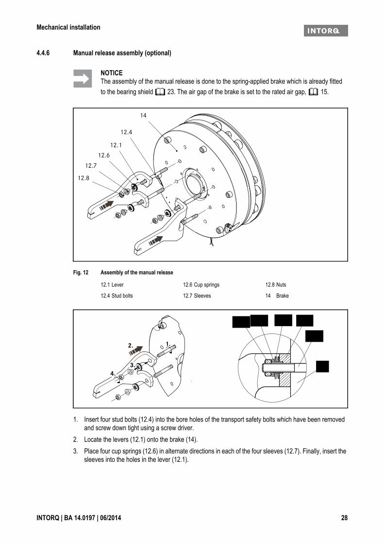
4.4.6 Manual release assembly (optional)
Fig. 12 Assembly of the manual release
1. Insert four stud bolts (12.4) into the bore holes of the transport safety bolts which have been removed and screw down tight using a screw driver.
2. Locate the levers (12.1) onto the brake (14).3. Place four cup springs (12.6) in alternate directions in each of the four sleeves (12.7). Finally, insert the
sleeves into the holes in the lever (12.1).
NOTICEThe assembly of the manual release is done to the spring-applied brake which is already fitted to the bearing shield 23. The air gap of the brake is set to the rated air gap, 15.
12.1 Lever 12.6 Cup springs 12.8 Nuts
12.4 Stud bolts 12.7 Sleeves 14 Brake
12.4
12.112.612.712.8
14

Mechanical installation
INTORQ | BA 14.0197 | 06/2014 29
4. Screw self-locking nuts (12.8) onto the stud bolts and tighten them until the dimension "s" has been set.
Fig. 13 Dimension "sL" and "s"
NOTICEBefore setting the dimension "s", it is imperative that the air gap "sL" is checked, and adjusted to "sLN" ( 15), if required. The brake is not energised during adjustment.
1.1 Stator, complete 6 Flange 12.1 Lever
2 Armature plate
Type sLN+0.05 [mm] s+0.1 [mm]
BFK464-17S
0.4 5.3
BFK464-18SBFK464-18S.2BFK464-19SBFK464-20SBFK464-20S.1BFK464-25SBFK464-25S.1BFK464-28S 0.5 6.5
DANGER
Brake may failIf the manual release is not adjusted correctly the brake may fail.Possible consequences:❚ Severe injuries or material damage.Protective measure:❚ Ensure that the dimension "s" is observed.
sL
6 2 1.1

Electrical installation
INTORQ | BA 14.0197 | 06/2014 30
5 Electrical installation
5.1 Electrical connection
5.1.1 Important notes
DANGER
There is a risk of injury by electrical shock!❚ Electrical connection must only be carried out by skilled personnel!❚ Only carry out connection work when no voltage is applied (no live parts)! There is a risk of
unintended start-ups or electric shock.
NOTICE
❚ It must be ensured that the supply voltage corresponds to the name plate data.
NOTICE
❚ If an emergency stop is carried out without the required suppressor circuit, the control unit may be destroyed.
❚ Observe the correct polarity of the suppressor circuit!
NOTICE
❚ To functionally test the individual brake circuits, the power supply must be able to be switched off individually. For a new over energisation when switching on, it is also neces-sary to open switches K1/K3.
❚ The protective circuitry contained in the INTORQ switching device BEG-561- - (terminals 3 and 4) is not permitted for use in the lift system. The protective circuitry
must be connected parallel to the brake coil here, 31.

Electrical installation
INTORQ | BA 14.0197 | 06/2014 31
5.1.2 Switching suggestions
Fig. 14 INTORQ BFK464 connection diagram
Switching on❚ K2/K4 must be switched on before or at the same time as K1/K3!Switching off❚ Normal - AC switching
- K2/K4 remain closed- K1/K3 open
❚ Emergency stop - DC switching- K1/K3 and K2/K4 are opened at the same time
5.2 Bridge/half-wave rectifiers (optional)
BEG-561- -The bridge/half-wave rectifiers are used to supply electromagnetic DC spring-applied brakes which are ap-proved for the use with such rectifiers. Other use is only permitted with the approval of INTORQ.Once a set overexcitation time has elapsed, the bridge/half-wave rectifiers switch over from bridge rectifica-tion to half-wave rectification. Depending on the design of the load, an improvement of the switching behav-iour or a reduction in performance is possible.

Electrical installation
INTORQ | BA 14.0197 | 06/2014 32
5.2.1 Assignment: Bridge/half-wave rectifier - brake size
Rectifier type Supply voltage Coil voltageRelease / holding
Assigned brake
[V AC] [V DC]
BEG-561-255-030
230 ±10% 205 / 103
BFK464-17SBEG-561-255-030 BFK464-18SBEG-561-255-030 BFK464-18S.2BEG-561-255-030 BFK464-19SBEG-561-255-030 BFK464-20SBEG-561-255-030 BFK464-20S.1BEG-561-255-130 BFK464-25SBEG-561-255-130 BFK464-25S.1BEG-561-255-130 BFK464-28SBEG-561-440-030-1
400 ±10% 360 / 180
BFK464-17SBEG-561-440-030-1 BFK464-18SBEG-561-440-030-1 BFK464-18S.2BEG-561-440-030-1 BFK464-19SBEG-561-440-030-1 BFK464-20SBEG-561-440-030-1 BFK464-20S.1BEG-561-440-130 BFK464-25SBEG-561-440-130 BFK464-25S.1BEG-561-440-130 BFK464-28S
NOTICEThe BFK464-25S.1 brake version in the voltage version 103 / 72 V, is operated by means of a switching device provided by the customer which reduces the coil voltage from 103 V DC to 72 V DC.

Electrical installation
INTORQ | BA 14.0197 | 06/2014 33
Fig. 15 Dimensions and possible installations of bridge/half-wave rectifier
5.2.2 Technical specifications
U1 input voltage (40 ... 60 Hz)
Dimensions Fastening options
Rectifier type Bridge/half-wave rectifier
Output voltage for bridge rectification 0.9 x U1
Output voltage for half-wave rectification 0.45 x U1
Ambient temperature (storage/operation) [°C] -25 – +70
Type Input voltage U1(40 Hz ... 60 Hz)
Max. current Imax Overexcitation time tü (± 20%)
min.[V ~ ]
Rated[V ~]
max.[V ~ ]
Bridge[A]
half-wave[A]
at U1 min[s]
at U1 Nenn[s]
at U1 max[s]
BEG-561-255-030160 230 255 3.0 1.5
0,430 0,300 0,270BEG-561-255-130 1,870 1,300 1,170BEG-561-440-030-1 230 400 440 1.5 0.75 0,500 0,300 0,270
Tab. 5: Data for bridge/half-wave rectifier type BEG-561

Electrical installation
INTORQ | BA 14.0197 | 06/2014 34
5.2.3 Permissible current load at ambient temperature
1 For screw assembly with metal surface (good heat dissipation)2 For other assembly (e.g. adhesive)
5.3 Electrical connection
DANGER
There is a risk of injury by electrical shock!The brake must only be electrically connected when no voltage is applied!
NOTICECompare the coil voltage of the stator to the DC voltage of the installed rectifier.
IImax.
u [°C]
1
2
0
0,2
0,4
0,6
0,8
1,0
-20 0 20 40 60 80 100

Commissioning and operation
INTORQ | BA 14.0197 | 06/2014 35
6 Commissioning and operation
6.1 Important notes
❚ The brakes are dimensioned in such a way that the given rated torques are reached safely after a short run-in process.
❚ However, as the organic friction linings used do not all have identical properties and because environ-mental conditions can vary, deviations from the specified braking torques are possible. These must be taken into account in the form of appropriate dimensioning tolerances. Increased breakaway torque is common in particular after long downtimes in humid environments where temperatures vary.
❚ Check the braking torque if the brake is inserted on the customer's friction surfaces.❚ If the brake is used as a pure holding brake without dynamic load, the friction lining must be reactivated
regularly.
6.2 Function checks before commissioning
6.2.1 Functional checks
Brake with microswitch
DANGER
❚ The live connections and the rotating rotor must not be touched.❚ The drive must not be running when checking the brake.
DANGER
Danger: rotating parts!The brake must be free of residual torque. The motor must not run!
DANGER
There is a risk of injury by electrical shock!Live connections must not be touched.

Commissioning and operation
INTORQ | BA 14.0197 | 06/2014 36
1. The switching contact for the brake must be open.2. Remove two bridges from the motor terminals to deenergise the motor.
- Do not disconnect the supply voltage for the brake. Apply DC voltage to the brake.
3. Apply DC voltage to the brake.4. Measure the AC voltage at the motor terminals. The measured level must be zero.5. Close the switching contact for the brake.
- The brake is released.6. Measure the DC voltage at the brake:
- The measured DC voltage after the overexcitation time (see bridge/half-wave rectifier, 32) must correspond to the holding voltage (see table 5). A deviation of ±10 % is permissible.
7. Check the air gap "sL".- It must be zero and the rotor must rotate freely.
8. Check the switching status of the microswitch (see table 6).9. Open the switching contact for the brake.
- The brake is applied.10. Check the switching status of the microswitch (see table 6).11. Switch off DC voltage for the brake.12. Screw the bridges onto the motor terminals.13. If necessary, remove the neutral conductor from the neutral point (step 2).
NOTICE
If the brake is connected to the neutral point of the motor, the PE conductor must also be con-nected to this point.
Contact type Connection Brake released Microswitch closed
NC contact black / greyyes nono yes
NO contact black / blueyes yesno no
Tab. 6: Switching status of the microswitch
Commissioning and operation
INTORQ | BA 14.0197 | 06/2014 37
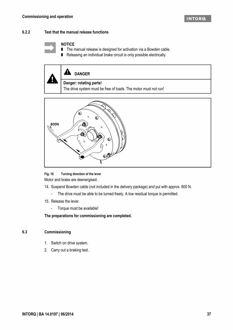
6.2.2 Test that the manual release functions
Fig. 16 Turning direction of the leverMotor and brake are deenergised.14. Suspend Bowden cable (not included in the delivery package) and pul with approx. 800 N.
- The drive must be able to be turned freely. A low residual torque is permitted.15. Release the lever.
- Torque must be available!The preparations for commissioning are completed.
6.3 Commissioning
1. Switch on drive system.2. Carry out a braking test.
NOTICE❚ The manual release is designed for activation via a Bowden cable.❚ Releasing an individual brake circuit is only possible electrically.
DANGER
Danger: rotating parts!The drive system must be free of loads. The motor must not run!
800N

Commissioning and operation
INTORQ | BA 14.0197 | 06/2014 38
6.4 During operation
❚ Checks must be carried out regularly. Pay special attention to:- unusual noises or temperatures- loose fixing elements- the condition of the electrical cables
❚ The armature plate must be attracted and the rotor must move without residual torque.❚ Measure the DC voltage at the brake.
- The measured DC voltage after the overexcitation time (see bridge/half-wave rectifier, 32) must correspond to the holding voltage (see table 5). A deviation of ±10 % is permissible.
❚ If faults occur once, go through the troubleshooting table in chapter 8. If the fault cannot be fixed or elim-inated, please contact your customer service.
DANGER
Danger: rotating parts!The running rotor must not be touched.
DANGER
There is a risk of injury by electrical shock!Live connections must not be touched.

Maintenance and repair
INTORQ | BA 14.0197 | 06/2014 39
7 Maintenance and repair
7.1 Wear of spring-applied brakes
INTORQ spring-applied brakes are wear-resistant and designed for long maintenance intervals. The friction lining and braking mechanism are subject to operational wear. For safe and trouble-free operation, the brake must be checked at regular intervals or replaced, if necessary 40.
The table below shows the different causes of wear and their impact on the components of the spring-applied brake. The influential factors must be quantified so that the service life of the rotor and brake can be calcu-lated and so that the prescribed maintenance intervals can be specified accurately. The most important fac-tors in this context are the applied friction energy, the initial speed of rotation of braking and the operating frequency. If several of the causes of friction lining wear occur in an application at the same time, the influ-encing factors should be added together when the amount of wear is calculated. The calculation of the ser-vice interval can be supported by the design program INTORQ-Select.
NOTICE
Braking torque reductionThe air gap must not be re-adjusted after it has been correctly adjusted during the initial installation of the brake on the motor! This could result in a loss of braking torque.
Component Cause Effect Influencing factors
Friction lining Braking during operation Wear of the friction lining Friction workEmergency stopsOverlapping wear during start and stop of driveActive braking via the drive motor with sup-port of brake (quick stop)Starting wear in case of motor mounting position with vertical shaft, even when the brake is not applied
Number of start/stop cycles
Armature plate and counter friction face
Rubbing of brake lining Run-in of armature plate and counter friction face
Friction work
Gear teeth of brake rotor
Relative movements and shocks between brake rotor and brake shaft
Wear of gear teeth (primarily on the rotor side)
Number of start/stop cycles
Brake support Load reversals and jerks in the backlash between armature plate, adjustment tubes and guide pins
Breaking of armature plate, adjustment tubes and guide pins
Number of start/stop cycles, braking torque
Springs Axial load cycle and shear stress of springs through radial backlash on reversal of arma-ture plate
Reduced spring force or fatigue failure
Number of switching operations of brake
Tab. 7: Causes for wear

Maintenance and repair
INTORQ | BA 14.0197 | 06/2014 40
7.2 Inspections
To ensure safe and trouble-free operations, the spring-applied brakes must be checked at regular intervals and, if necessary, be replaced. Servicing will be easier at the plant if the brakes are made accessible. This must be considered when installing the drives in the plant.Primarily, the required maintenance intervals for industrial brakes result from their load during operation. When calculating the maintenance interval, all causes for wear must be taken into account, 39. For brakes with low loads (such as holding brakes with emergency stop function), we recommend a regular in-spection at a fixed time interval. To reduce costs, the inspection can be carried out along with other regular maintenance work in the plant.Failures, production losses or damage to the system may occur when the brakes are not serviced. Therefore, a maintenance strategy that is adapted to the particular operating conditions and brake loads must be de-fined for every application. For the spring-applied brakes, the maintenance intervals and maintenance oper-ations listed in the table below must be followed. The maintenance operations must be carried out as described in the detailed descriptions.
7.2.1 Maintenance intervals
Type Time interval
for service brakes: for holding brakes with emergency stop:
BFK464 -S/S.1/S.2
❚ according to service life cal-culation
❚ or else every six months❚ after 4000 operating hours
at the latest
❚ at least every two years❚ after 1 m cycles at the latest
Maintenance
Inspections with assembled brake: Inspections after the brake has been removed:
❚ Check release function and control
42 ❚ Check the play of the rotor toothing (replace worn-out ro-tors)
42
❚ Measure the air gap (adjust if required)
25 ❚ Breaking out of the torque support at the sleeve bolts and the armature plate
❚ Measure the rotor thickness (replace rotor if required)
42 ❚ Check the springs for damage
❚ Thermal damage of the ar-mature plates or flange (dark-blue tarnishing)
❚ Check the armature plate and flange or bearing shield- Levelness < 0.1 mm- Max. run-in depth = rated
air gap of the size

Maintenance and repair
INTORQ | BA 14.0197 | 06/2014 41
7.3 Maintenance
7.3.1 Check the rotor thickness
1. Stop motor and control system!2. Remove the motor cover and remove the cover ring, if present.3. Measure the rotor thickness using a caliper gage.4. Compare the measured rotor thickness against the minimal permitted rotor thickness ( 15).5. If required, replace the rotor completely. Description, see 42.
7.3.2 Check the air gap
1. Stop motor and control system!2. Measure the air gap "sL" near the fixing screws between the armature plate and the stator using a feeler
gauge.3. Compare the measured air gap with the maximum permitted air gap "sLmax" ( 15).4. If required, replace the rotor completely. Description, see 42.
NOTICEBrakes with defective armature plates, socket head cap screws, springs or counter friction faces must always be replaced completely.Generally observe the following for inspections and maintenance works:❚ Contamination by oils and greases should be removed using brake cleaner, or the brake
should be replaced after determining the cause. Dirt and particles in the air gap between the stator and the armature plate endanger the function and should be removed.
❚ After replacing the rotor, the original braking torque will not be reached until the run-in op-eration for the friction surfaces has been completed. After replacing the rotor, the run-in ar-mature plates and counter friction faces have an increased initial rate of wear.
DANGER
Danger: rotating parts! The motor must not run during the check.
DANGER
Danger: rotating parts! The motor must not run during the check.

Maintenance and repair
INTORQ | BA 14.0197 | 06/2014 42
7.3.3 Release / voltage
1. Start motor and control system!
2. Observe the air gap "sL" when the drive is running. It should be zero.3. Measure the DC voltage at the brake.
- After the overexcitation time (see bridge/half-wave rectivier, 32), the measured DC voltage must correspond to the holding voltage ( 33). A deviation of ±10 % is permissible.
7.3.4 Replacing the rotor
1. Switch off voltage!2. Disconnect the connection cable.3. Loosen the screws evenly and remove them completely.4. Remove the complete stator from the bearing shield. Pay attention to the connection cable.5. Pull the complete rotor from the hub.6. Check the toothing of the hub.7. Replace the hub too if it is worn.8. Check the friction surface on the bearing shield. In case of strong scoring at the flange, replace the
flange. In case of strong scoring on the bearing shield, rework the friction surface.9. Measure the rotor thickness (new rotor) and head height of the sleeve bolts with a calliper gauge.10. Calculate the distance between the stator and the armature plate as follows:
Distance = rotor thickness + sLN - head height
("sLN" 15)
11. Unscrew the sleeve bolts evenly until the calculated distance between stator and armature plate is reached.
12. Install and adjust the new complete rotor and stator, 24.13. Reconnect the connection cable.
DANGER
Danger: rotating parts! The running rotor must not be touched.
DANGER
There is a risk of injury by electrical shock!Live connections must not be touched.
DANGER
Danger: rotating parts! The brake must be free of residual torque.
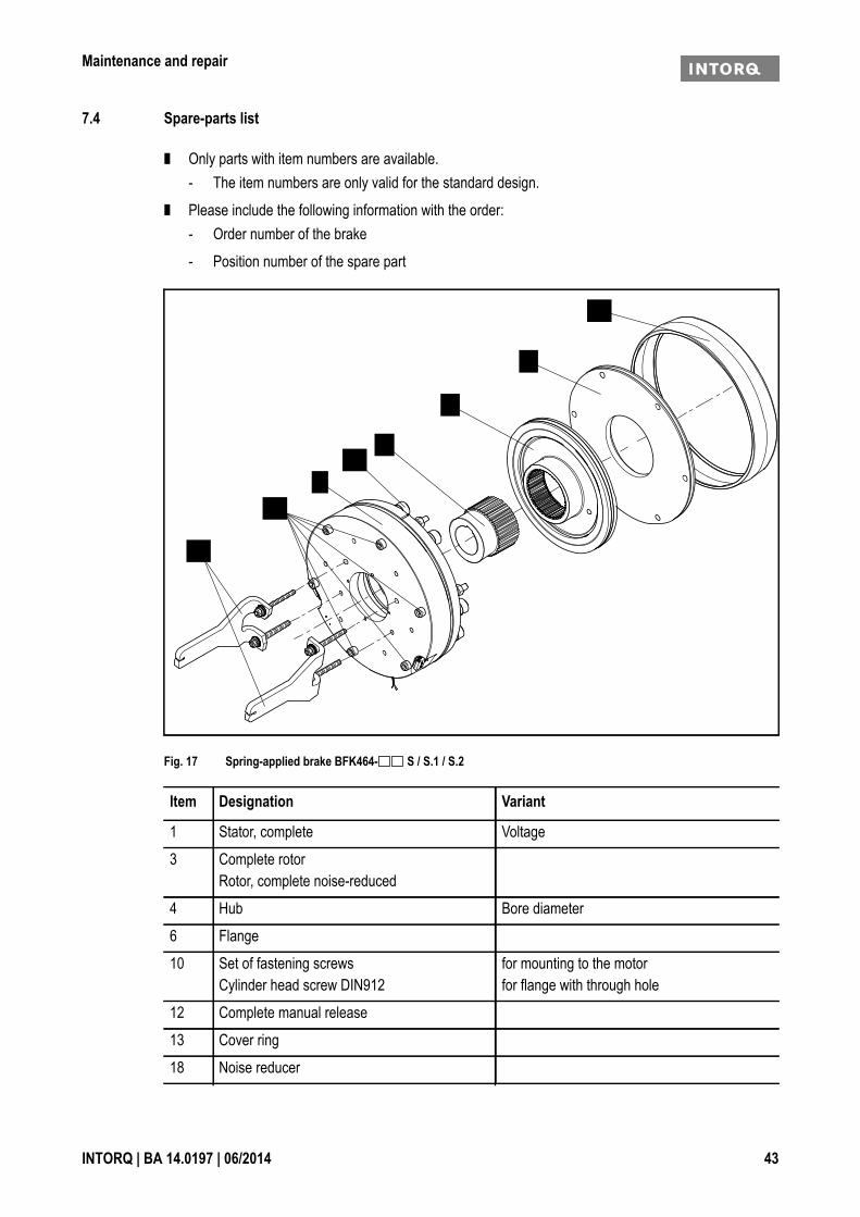
Maintenance and repair
INTORQ | BA 14.0197 | 06/2014 43
7.4 Spare-parts list
❚ Only parts with item numbers are available.- The item numbers are only valid for the standard design.
❚ Please include the following information with the order:- Order number of the brake- Position number of the spare part
Fig. 17 Spring-applied brake BFK464- S / S.1 / S.2
Item Designation Variant
1 Stator, complete Voltage3 Complete rotor
Rotor, complete noise-reduced4 Hub Bore diameter6 Flange10 Set of fastening screws
Cylinder head screw DIN912for mounting to the motorfor flange with through hole
12 Complete manual release13 Cover ring18 Noise reducer
3
4
6
1
10
12
13
18

Maintenance and repair
INTORQ | BA 14.0197 | 06/2014 44
7.5 Ordering spare parts
INTORQ BFK464- S / S.1 / S.2, stator, complete
Accessories
Electrical accessoriesRectifier type: Selection see chapter 5.2.1
Size 17 18 19 20 25 28
Design S S.1 S.2
Voltage 103 V / 51.5 V 103 V / 72 V 205 V / 103 V 360 V / 180 V
Braking torque Nm
Standard (600 mm)
Cable length mm (from 100-1000 mm in 100 mm steps, from 1000-2500 mm in 250 mm steps)
Manual release mounted
Armature plate Standard
Microswitch Monitoring the switching function
Switching noises Damped
Rotor Aluminium Noise-reduced (rotor with sleeve)
Hub mm (for hole diameter, see dimensions)
Flange
Fixing screw set for mounting to the motor for mounting to the flange with pass-through holes
Sealing Cover ring Shaft seal ring (shaft diameter on request) Cap
Noise reduction Noise reducer set
Rectifier BEG-561-255-030 BEG-561-255-130 BEG-561-440-030-1 BEG-561-440-130

Troubleshooting and fault elimination
INTORQ | BA 14.0197 | 06/2014 45
8 Troubleshooting and fault elimination
If any malfunctions should occur when operating the braking system, please check for possible causes based on the following table. If the fault cannot be fixed or eliminated by one of the listed measures, please contact the customer service.
Maloperation of the brake
Fault Cause RemedyBrake does not release Coil interruption ❚ Measure coil resistance using a multimeter:
- If resistance is too high, replace the complete stator.Coil has contact to earth or between windings
❚ Measure the coil resistance using a multimeter:- Compare the measured resistance with the nominal
resistance. Values, see 15. If resistance is too low, replace the complete stator.
❚ Check the coil for short to ground using a multimeter:- If there is a short to ground, replace the complete
stator.❚ Check the brake voltage (see Defective rectifier, volt-
age too low).Wiring defective or wrong ❚ Check and correct
❚ cable for continuity using a multimeter- Replace defective cable.
Rectifier defective or incorrect ❚ Measure rectifier DC voltage using a multimeter.If DC voltage is zero:❚ Check AC rectifier voltage. If AC voltage is zero:
- Switch on power supply- Check fuse- Check wiring.
If AC voltage is ok:- Check rectifier,- Replace defective rectifier- Diode defective, use suitable new rectifier
❚ Check the coil for winding short or ground short.❚ If the rectifier defect occurs again, replace the entire
stator, even if you cannot find any fault between turns or short circuit to ground. The error may only occur on warming up.

Troubleshooting and fault elimination
INTORQ | BA 14.0197 | 06/2014 46
Brake does not release Microswitch incorrectly wired Check the wiring of the microswitch and correct it.Microswitch incorrectly set Replace the complete stator and complain about the set-
ting of the microswitch to the manufacturer.Air gap too big Adjust the air gap ( 26)
Measure the rotor thickness and compare against the min-imum rotor thickness ( 15). If required, replace the rotor.
Rotor cannot rotate freely Wrong setting of manual release
Check the dimension "s+sL" with the brake energised. The dimension must be the same on both sides. Correct if required.
Air gap "sL" too small Check air gap "sL" and adjust it if necessary ( 26).Rotor thickness too small Rotor has not been replaced
in timeReplace the rotor ( 42).
Voltage is not zero during the functional test (chap. 6.2)
Microswitch incorrectly wired Check and correct the wiring of the microswitch.Microswitch defective or incorrectly set
Replace the complete stator and send the complete stator to the manufacturer.
Voltage too high Brake voltage does not match the rectifier
Adjust rectifier and brake voltage to each other.
Voltage too low Brake voltage does not match the rectifier
Adjust rectifier and brake voltage to each other.
AC voltage is not mains voltage
Fuse is missing or defective Select a connection with proper fusing.Microswitch incorrectly wired Check and correct the wiring of the microswitch.Microswitch defective or incorrectly set
Replace the complete stator and return the defective com-plete stator to the manufacturer.
Fault Cause Remedy

Installation and Operational Instructions for ROBA®-twinstop®
Type 8012._ _ _ _ _ Sizes 150 to 350 (B.8012.GB)
05/07/2010 TK/HW/SU Chr. Mayr GmbH + Co. KG Tel.: 08341 / 804-0Eichenstraße 1 Fax: 08341 / 804-421 D-87665 Mauerstetten http://www.mayr.de
Page 1 of 15 Germany eMail: [email protected]
Please read these Operational Instructions carefully and follow them accordingly! Ignoring these Instructions can lead to lethal accidents, malfunctions, brake failure and damage to other parts.
Contents:
Page 1: - Contents - Declaration of Conformity - Safety and Guideline Signs - TÜV (German Technical Inspectorate) Certification
Page 2: - Safety Regulations
Page 3: - Safety Regulations
Page 4: - Brake Illustrations
Page 5: - Parts List
Page 6: - Table 1: Technical Data - Table 2: Technical Data
Page 7: - Table 3: Technical Data - Table 4: Switching Times - Torque-Time Diagram
Page 8: - Design - Function - State of Delivery - Application - Installation Conditions
Page 9: - Installation of Type 8012._0_ _3 - Installation of Type 8012._1_ _3
Page 10: - Hand Release - Braking Torque Adjustment - Noise Damping
Page 11: - Release Monitoring
Page 12: - Wear Monitoring
Page 13: - Electrical Connection (Operation with Nominal Voltage)
Page 14: - Electrical Connection (Operation with Overexcitation)
Page 15: - Brake Inspection (Customer-side after Installation) - Dual Circuit Brake Functional Inspection - Maintenance - Disposal - Malfunctions / Breakdowns
Declaration of Conformity A conformity evaluation for the applicable EU directives has been carried out for this product. The conformity evaluation is set out in writing in a separate document and can be requested if required. It is forbidden to start use of the product until you have ensured that all applicable EU directives and directives for the machine or system into which the product has been installed have been fulfilled. Without a conformity evaluation, this product is not suitable for use in areas where there is a high danger of explosion. This statement is based on the ATEX directive.
Safety and Guideline Signs
Danger!Danger of injury to personnel and damage to machines.
Please Observe!Guidelines on important points.
TÜV (German Technical Inspectorate) Certification License number: ABV 845
Please Observe!According to German notation, decimal points in this document are represented with a comma (e.g. 0,5 instead of 0.5).

Installation and Operational Instructions for ROBA®-twinstop®
Type 8012._ _ _ _ _ Sizes 150 to 350 (B.8012.GB)
05/07/2010 TK/HW/SU Chr. Mayr GmbH + Co. KG Tel.: 08341 / 804-0Eichenstraße 1 Fax: 08341 / 804-421 D-87665 Mauerstetten http://www.mayr.de
Page 2 of 15 Germany eMail: [email protected]
Safety Regulations These Safety Regulations are user hints only and may not be complete!
Danger!Danger of death! Do not touch voltage-carrying cables and components.
To prevent injury or damage, only professionals and specialists should work on the devices.
Danger!
This warning applies if: the electromagnetic brake is used incorrectly. the electromagnetic brake is modified. the relevant standards for safety and / or installation
conditions are ignored.
Please Observe!Before product installation and initial operation, please read the Installation and Operational Instructions carefully and
observe the Safety Regulations. Incorrect operation can cause injury or damage. The electromagnetic brakes have been developed in accordance with the latest technology regulations and are, at the point of delivery, operationally safe.
Please Observe! Only specialists who are trained in the transport,
installation, operation, maintenance and general operation of these devices and who are aware of the relevant standards should be allowed to carry out this work.
Technical data and specifications (Type tags and documentation) must be followed.
The correct connection voltage must be connected according to the Type tag.
Never loosen electrical connections or carry out installations, maintenance or repairs while the voltage connection is energised!
Cable connections must not be placed under mechanical strain.
Check electrical components for signs of damage before putting them into operation. Never bring them into contact with water or other fluids.
The braking torque is lost if the friction lining and / or the friction surface come into contact with oil or grease.
Please Observe! Please ensure that the brake is clean and oil-free, as both brake circuits have an effect on the same linings. Special sealing
measures, among other precautions, may be necessary - in particular in gear applications!
Appointed Use This safety brake is intended for use in electrically operated elevators and goods elevators according to EC 81-1/1998. The safety brake corresponds to DIN EN 81, Part 1 [Sections 12.4.2.1 (2nd Paragraph), 12.4.2.2, and 12.4.2.5] in its general design and its mode of operation. The effectiveness of the mechanical dual circuit system can be tested at the place of operation (requirement acc. TRA 102).
Guidelines for Electromagnetic Compatibility (EMC) In accordance with the EMC directives 2004/108/EC, the individual components produce no emissions. However, functional components e.g. mains-side energisation of the brakes with rectifiers, phase demodulators, ROBA®-switch devices or similar controls can produce disturbance which lies above the allowed limit values. For this reason it is important to read the Installation and Operational Instructions very carefully and to keep to the EMC directives.
Device Conditions Please Observe! When dimensioning the brakes, please remember that installation situations, braking torque fluctuations, permitted
friction work, run-in behaviour and wear as well as general ambient conditions can all affect the given values. These factors should therefore be carefully assessed, and alignments made accordingly.
Please Observe! Mounting dimensions and connecting dimensions must be
adjusted according to the size of the brake at the place of installation.
Use of the brake in extreme environmental conditions or outdoors, directly exposed to the weather, is not permitted.
The magnetic coils are designed for 100 % duty cycle. However, a switch-on duration of > 60 % duty cycle results in increased temperatures, which cause premature aging on the noise damping system, and therefore to an increase in switching noises. The max. permitted switching frequency is 240 1/h. If the brakes are overexcited, a switching frequency of 180 1/h must not be exceeded. These values apply for intermittent duty S3 60%. The permitted surface temperature on the brake flange must not exceed 80 °C and a max. ambient temperatur e of 45 °C. The duration of overexcitation should be approx. 1 second.
The brakes are only designed for dry running. The torque is lost if the friction surfaces come into contact with oil, grease, water or similar substances.
The braking torque is dependent on the present run-in condition of the brakes.
Manufacturer-side corrosion protection of the metal surface is provided. The surface is rough sawn and not machined (milled material).
Protection Class I This protection can only be guaranteed if the basic insulation is intact and if all conductive parts are connected to the PE conductor of the permanent installation. Should the basic insulation fail, the contact voltage cannot remain (VDE 0580).
Ambient Temperature 0 °C up to +45 °C Danger! At temperatures of around or under freezing point, condensation can strongly reduce the torque, or the rotors can freeze up. The user is responsible for taking appropriate counter measures.

Installation and Operational Instructions for ROBA®-twinstop®
Type 8012._ _ _ _ _ Sizes 150 to 350 (B.8012.GB)
05/07/2010 TK/HW/SU Chr. Mayr GmbH + Co. KG Tel.: 08341 / 804-0Eichenstraße 1 Fax: 08341 / 804-421 D-87665 Mauerstetten http://www.mayr.de
Page 3 of 15 Germany eMail: [email protected]
Safety Regulations These Safety Regulations are user hints only and may not be complete!
Insulation Material Class F (+155 °C) The magnetic coil and the casting compound are suitable for use up to a maximum operating temperature of +155 °C.
Brake Storage Store the brakes in a horizontal position, in dry rooms and
dust and vibration-free. Relative air humidity < 60 %. Temperature without major fluctuations within a range from
– 20 ° up to +60° C. Do not store in direct sunlight or UV light. Do not store aggressive, corrosive substances (solvents /
acids / lyes / salts etc.) near to the brakes. For longer storage of more than 2 years, special measures are required (please contact the manufacturers).
Handling Before installation, the brake must be inspected and found to be in proper condition. The brake function must be inspected both once installation has taken place as well as after longer system downtimes, in order to prevent the drive starting up against possibly seized linings.
User-implemented Protective Measures: Please cover moving parts to protect against injury through
seizure. Place a cover on the magnetic part to protect against injury
through high temperatures. Protect against electric shocks by installing a conductive
connection between the magnetic component and the PE conductor on the permanent installation (Protection Class I) and by carrying out a standardised inspection of the continuous PE conductor connection to all contactable metal parts.
Protect against highly inductive switch-off peaks by installing varistors, spark quenching units or similar devices according to VDE 0580/2000-07, Paragraph 4.6, to prevent damage to the coil insulations or switch contact consumption in extreme conditions (this protection is contained in mayr® rectifiers).
Take precautions against freeze-up of the friction surfaces in high humidity and at low temperatures.
Regulations, Standards and Directives Used: DIN VDE 0580 Electromagnetic devices and components, general directives 2006/95/EC Low voltage directive 2004/108/EC EMC directive 95/16/EC Elevator directive EN 81-1 Safety regulations for
construction and installation of elevators and small goods elevators
BGV C1 (previously VGB 70) Safety regulations for theatre stage technical systems
Please Observe the Following Standards: DIN EN ISO 12100-1 and 2 Machine Safety DIN EN 61000-6-4 Noise emission EN12016 Interference resistance
(for elevators, escalators and moving walkways)
EN 60204 Electrical machine equipment
Liability The information, guidelines and technical data in these
documents were up to date at the time of printing. Demands on previously delivered brakes are not valid.
Liability for damage and operational malfunctions will not be taken if - the Installation and Operational Instructions are ignored or neglected. - the brakes are used inappropriately. - the brakes are modified. - the brakes are worked on unprofessionally. - the brakes are handled or operated incorrectly.
Guarantee The guarantee conditions correspond with the
Chr. Mayr GmbH + Co. KG delivery conditions. Mistakes or deficiencies are to be reported to mayr ® at
once!
Conformity Markings The product confirms to the CE according to the low voltage directive 2006/95/EC.
Identification mayr ® components are clearly marked and described on the Type tag:
Manufacturer
mayr ®
Name/Type Article number Serial number

Installation and Operational Instructions for ROBA®-twinstop®
Type 8012._ _ _ _ _ Sizes 150 to 350 (B.8012.GB)
05/07/2010 TK/HW/SU Chr. Mayr GmbH + Co. KG Tel.: 08341 / 804-0Eichenstraße 1 Fax: 08341 / 804-421 D-87665 Mauerstetten http://www.mayr.de
Page 4 of 15 Germany eMail: [email protected]
Fig. 1 Fig. 2
Fig. 3 Fig. 4
5
2
4 (4x)
1
1.1
6
12
1.1
6.6
5/9 (4x)
14 (8x)
1
13 Brake 1
Brake 2
1
2
3
2
8
Customer-side splined shaft
Air gap "b"
Air gap "b"
+0,2-0,05
+0,2-0,05
Air gap "a" 0,45
Air gap "a" 0,45
1
3
2
11
2
10
Air gap "b"
Air gap "b"
+0,2-0,05
+0,2-0,05
Air gap "a" 0,45
Air gap "a" 0,45

Installation and Operational Instructions for ROBA®-twinstop®
Type 8012._ _ _ _ _ Sizes 150 to 350 (B.8012.GB)
05/07/2010 TK/HW/SU Chr. Mayr GmbH + Co. KG Tel.: 08341 / 804-0Eichenstraße 1 Fax: 08341 / 804-421 D-87665 Mauerstetten http://www.mayr.de
Page 5 of 15 Germany eMail: [email protected]
Parts List (Only use mayr original parts)
Item Name 1 Coil carrier assembly (incl. magnetic coils) 1.1 Coil cable 2 x AWG18 blue / brown 2 Armature disk 3 Rotor 4 Distance bolts
5
Hexagon head screw acc. DIN EN ISO 4014: For Sizes 150 and 200: M8 x 110 / 8.8 For Size 250: M8 x 120 / 10.9 For Size 350: M10 x 120 / 8.8
6 Release monitoring assembly 6.1 Microswitch incl. adapter plate (Fig. 9; page 11) 6.2 Cap screw (Fig. 9; page 11) 6.3 Hexagon nut (Fig. 9; page 11) 6.4 Hexagon head screw (Fig. 9; page 11) 6.5 Spring washer (Fig. 9; page 11) 6.6 Microswitch cable 3 x AWG20 black / blue / brown 7 Hand release assembly (page 10) 7.1 Hand release lever (page 10) 7.2 Steel ball (page 10) 7.3 Thrust spring (page 10) 7.4 Cap screw (page 10) 7.5 Hexagon nut (page 10) 7.6 Washer (page 10)
8
O-ring NBR 70 (not included in delivery): For Sizes 150 and 200: D48 x 3 For Size 250: D52 x 3 For Size 350 (braking torque up to 410 Nm): D52 x 3For Size 350 (braking torque > 410 Nm): D60 x 3
9 Washer 10 Hub 11 O-ring 12 Cable clamp 13 Type tag 14 Noise damping 15 Wear monitoring assembly (page 12) 15.1 Microswitch incl. adapter plate (Fig. 10; page 12) 15.2 Cap screw (Fig. 10; page 12) 15.3 Hexagon nut (Fig. 10; page 12) 15.4 Hexagon head screw (Fig. 10; page 12) 15.5 Spring washer (Fig. 10; page 12)

Installation and Operational Instructions for ROBA®-twinstop®
Type 8012._ _ _ _ _ Sizes 150 to 350 (B.8012.GB)
05/07/2010 TK/HW/SU Chr. Mayr GmbH + Co. KG Tel.: 08341 / 804-0Eichenstraße 1 Fax: 08341 / 804-421 D-87665 Mauerstetten http://www.mayr.de
Page 6 of 15 Germany eMail: [email protected]
Table 1: Technical Data (independent of Type and Size)
Nominal air gap 1) "a" braked (Fig. 3) 0,45 2,005,0
+− mm
Limit air gap 2) "a" for rotor replacement 0,9 mm
Inspection air gap "b" on released brake (Fig. 3) min. 0,25 mm
Protection (coil/casting compound): IP54
Protection (mechanical): IP10
Protection (switch): IP67
Ambient temperature: 0 °C to +45 °C
Duty cycle: 60 %1) Measured in the horizontal centre axis area of the respective armature disk (2).
2) Danger! The tension ability of the brake increases, above all when operating with reduced torques and / or in operation with overexcitation. Due to the brake noise behaviour and for reasons of safety, the rotor (3) must however be replaced at the latest when the air gap reaches 0,9 mm (see section on Maintenance, page 15). If there is still a risk of the device wearing down to an air gap of 0,9 mm unnoticed, we recommend mounting a wear monitoring device (available on request). When the air gap reaches "a" > 2,0 mm (design with hand release) or "a" > 2,5 mm (design without hand release), the armature disk (2) will lie against the mechanical contacts, which causes a sudden drop in braking torque to 0 Nm and a risk of load crashes.
Table 2: Technical Data
Size Nominal torque 3)
minimal
Overexcitation voltage
1,5 to 2 x U Nom
Nominal voltage U Nom
Nominal capacityP (20 °C)
Inductivity (207 V – coil)
Rotor thicknessin new condition
90 Nm 120 Nm 150 Nm
No 24/104/180/207 V DC 2 x 68 W 18 –0.05 mm 150
4) > 150 Nm Yes 24/104/180/207 V DC 18 –0.05 mm 120 Nm 160 Nm 200 Nm
No 24/104/180/207 V DC 2 x 63 W 18 –0.05 mm 200
4) > 200 Nm Yes 24/104/180/207 V DC 18 –0.05 mm 185 Nm 230 Nm 250 Nm 280 Nm
No 24/104/180/207 V DC 2 x 79 W 18 –0.05 mm 250
4) > 280 Nm Yes 24/104/180/207 V DC 18 –0.05 mm 250 Nm 300 Nm 350 Nm 410 Nm
No 24/104/180/207 V DC 2 x 82 W 18 –0.05 mm 350
4) > 410 Nm Yes 24/104/180/207 V DC 18 –0.05 mm 3) The braking torque (nominal torque) is the torque effective in the shaft train on slipping brakes, with a sliding speed of 1 m/s referring to the medium friction radius. 4) Larger braking torques available on request

Installation and Operational Instructions for ROBA®-twinstop®
Type 8012._ _ _ _ _ Sizes 150 to 350 (B.8012.GB)
05/07/2010 TK/HW/SU Chr. Mayr GmbH + Co. KG Tel.: 08341 / 804-0Eichenstraße 1 Fax: 08341 / 804-421 D-87665 Mauerstetten http://www.mayr.de
Page 7 of 15 Germany eMail: [email protected]
Table 3: Technical Data
Size Max. permitted friction work
per single circuit 5)
Inspected max. speed in the elevator area as
prototype-inspected brake
Tightening torque on fixing screw
Item 5 Weight 150 17500 J 1000 rpm 24 Nm 19,6 kg 200 16500 J 1000 rpm 24 Nm 23,7 kg 250 25500 J 1000 rpm 36 Nm 27,0 kg 350 23500 J 1000 rpm 48 Nm 34,9 kg
5) Values apply for a speed of 400 rpm and nominal torque. The value can be doubled for both brake circuits. The value increases at lower speeds and decreases at higher speeds (please contact mayr ®).
Table 4: Switching Times
Size Nominal torque
minimal Tightening t2 Tightening t2 on
overexcitation Drop-out t11
AC Drop-out t1
AC Drop-out t11
DC Drop-out t1
DC 90 Nm 145 250 570 35 140
120 Nm 170 200 510 27 125 150 Nm 200 150 450 20 110
150
> 150 Nm Approx. 120 120 Nm 170 420 980 75 230 160 Nm 225 310 790 53 195 200 Nm 280 190 620 30 160
200
> 200 Nm Approx. 170 185 Nm 210 300 720 50 180 230 Nm 260 240 640 40 165 250 Nm 285 215 590 37 155 280 Nm 310 180 540 25 140
250
> 280 Nm Approx. 190 250 Nm 290 370 700 45 150 300 Nm 330 320 640 40 140 350 Nm 370 270 580 37 130 410 Nm 400 200 510 30 110
350
> 410 Nm Approx. 240
Please Observe: The use of varistors for spark quenching increases the DC-side switching times. At temperatures of around or under freezing point, condensation can strongly reduce the braking torque.
The user is responsible for taking appropriate counter measures. The customer is responsible for providing a protective cover against contamination caused by construction sites.
Torque-Time Diagram
Key: M1 = Switching torque M2 = Nominal torque (characteristic torque) M4 = Transmittable torque M6 = Load torque t1 = Connection time t11 = Response delay on connection t2 = Separation time t21 = Response delay on separation t4 = Slipping time + t11
M
M2
M6
t11 t21
t2
t
t
Pt4
t1
M1
M4
0,1 M2
ON
OFF
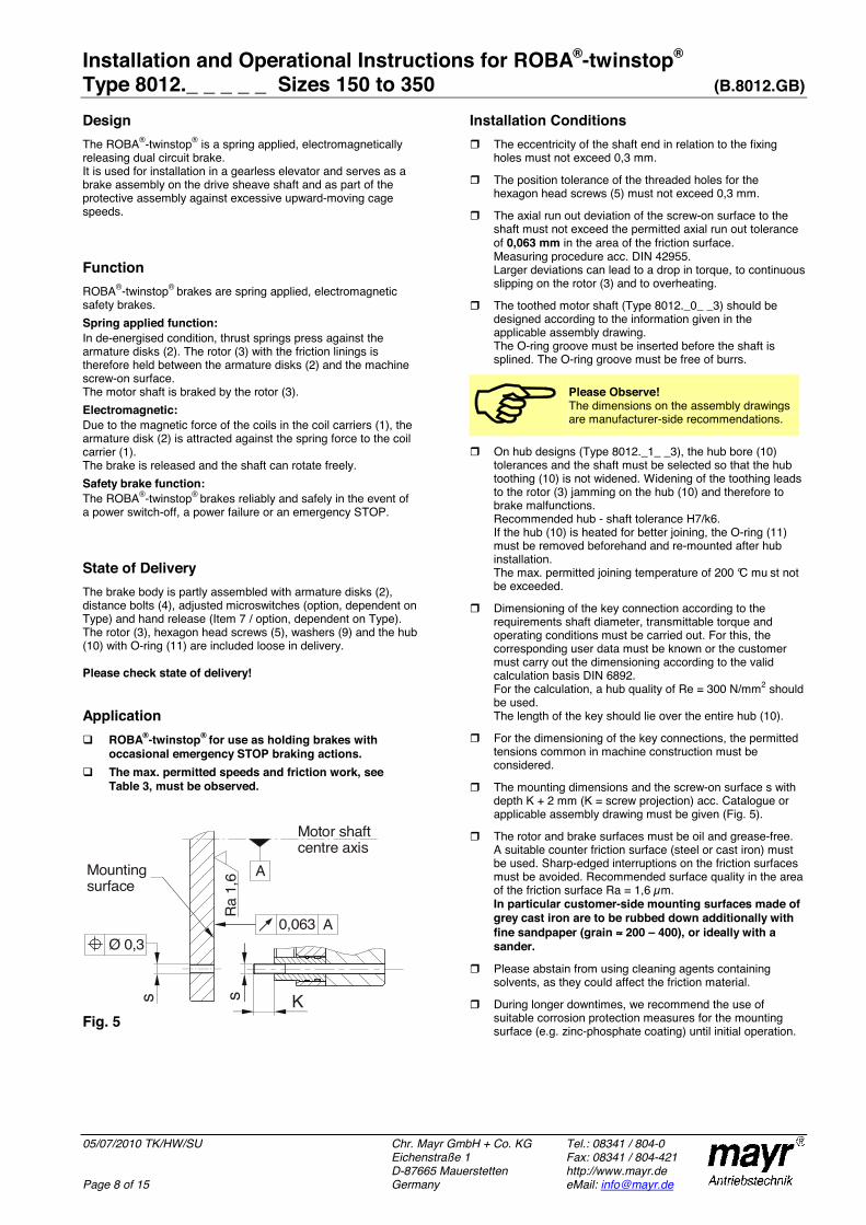
Installation and Operational Instructions for ROBA®-twinstop®
Type 8012._ _ _ _ _ Sizes 150 to 350 (B.8012.GB)
05/07/2010 TK/HW/SU Chr. Mayr GmbH + Co. KG Tel.: 08341 / 804-0Eichenstraße 1 Fax: 08341 / 804-421 D-87665 Mauerstetten http://www.mayr.de
Page 8 of 15 Germany eMail: [email protected]
Design The ROBA®-twinstop® is a spring applied, electromagnetically releasing dual circuit brake. It is used for installation in a gearless elevator and serves as a brake assembly on the drive sheave shaft and as part of the protective assembly against excessive upward-moving cage speeds.
Function ROBA®-twinstop® brakes are spring applied, electromagnetic safety brakes. Spring applied function: In de-energised condition, thrust springs press against the armature disks (2). The rotor (3) with the friction linings is therefore held between the armature disks (2) and the machine screw-on surface. The motor shaft is braked by the rotor (3). Electromagnetic: Due to the magnetic force of the coils in the coil carriers (1), the armature disk (2) is attracted against the spring force to the coil carrier (1). The brake is released and the shaft can rotate freely. Safety brake function: The ROBA®-twinstop® brakes reliably and safely in the event of a power switch-off, a power failure or an emergency STOP.
State of Delivery The brake body is partly assembled with armature disks (2), distance bolts (4), adjusted microswitches (option, dependent on Type) and hand release (Item 7 / option, dependent on Type). The rotor (3), hexagon head screws (5), washers (9) and the hub (10) with O-ring (11) are included loose in delivery.
Please check state of delivery!
Application ROBA®-twinstop® for use as holding brakes with
occasional emergency STOP braking actions. The max. permitted speeds and friction work, see
Table 3, must be observed.
Fig. 5
Installation Conditions The eccentricity of the shaft end in relation to the fixing
holes must not exceed 0,3 mm.
The position tolerance of the threaded holes for the hexagon head screws (5) must not exceed 0,3 mm.
The axial run out deviation of the screw-on surface to the shaft must not exceed the permitted axial run out tolerance of 0,063 mm in the area of the friction surface. Measuring procedure acc. DIN 42955. Larger deviations can lead to a drop in torque, to continuous slipping on the rotor (3) and to overheating.
The toothed motor shaft (Type 8012._0_ _3) should be designed according to the information given in the applicable assembly drawing. The O-ring groove must be inserted before the shaft is splined. The O-ring groove must be free of burrs.
Please Observe! The dimensions on the assembly drawings are manufacturer-side recommendations.
On hub designs (Type 8012._1_ _3), the hub bore (10) tolerances and the shaft must be selected so that the hub toothing (10) is not widened. Widening of the toothing leads to the rotor (3) jamming on the hub (10) and therefore to brake malfunctions. Recommended hub - shaft tolerance H7/k6. If the hub (10) is heated for better joining, the O-ring (11) must be removed beforehand and re-mounted after hub installation. The max. permitted joining temperature of 200 °C mu st not be exceeded.
Dimensioning of the key connection according to the requirements shaft diameter, transmittable torque and operating conditions must be carried out. For this, the corresponding user data must be known or the customer must carry out the dimensioning according to the valid calculation basis DIN 6892. For the calculation, a hub quality of Re = 300 N/mm2 should be used. The length of the key should lie over the entire hub (10).
For the dimensioning of the key connections, the permitted tensions common in machine construction must be considered.
The mounting dimensions and the screw-on surface s with depth K + 2 mm (K = screw projection) acc. Catalogue or applicable assembly drawing must be given (Fig. 5).
The rotor and brake surfaces must be oil and grease-free. A suitable counter friction surface (steel or cast iron) must be used. Sharp-edged interruptions on the friction surfaces must be avoided. Recommended surface quality in the area of the friction surface Ra = 1,6 µm. In particular customer-side mounting surfaces made of grey cast iron are to be rubbed down additionally with fine sandpaper (grain ≈≈≈≈ 200 – 400), or ideally with a sander.
Please abstain from using cleaning agents containing solvents, as they could affect the friction material.
During longer downtimes, we recommend the use of suitable corrosion protection measures for the mounting surface (e.g. zinc-phosphate coating) until initial operation.
0,063 A
A
Ra 1
,6
Ks s
Ø 0,3
Mountingsurface
Motor shaft centre axis
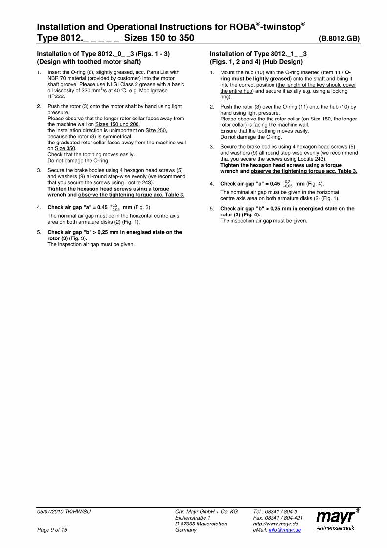
Installation and Operational Instructions for ROBA®-twinstop®
Type 8012._ _ _ _ _ Sizes 150 to 350 (B.8012.GB)
05/07/2010 TK/HW/SU Chr. Mayr GmbH + Co. KG Tel.: 08341 / 804-0Eichenstraße 1 Fax: 08341 / 804-421 D-87665 Mauerstetten http://www.mayr.de
Page 9 of 15 Germany eMail: [email protected]
Installation of Type 8012._0_ _3 (Figs. 1 - 3) (Design with toothed motor shaft) 1. Insert the O-ring (8), slightly greased, acc. Parts List with
NBR 70 material (provided by customer) into the motor shaft groove. Please use NLGI Class 2 grease with a basic oil viscosity of 220 mm2/s at 40 °C, e.g. Mobilgrease HP222.
2. Push the rotor (3) onto the motor shaft by hand using light pressure. Please observe that the longer rotor collar faces away from the machine wall on Sizes 150 und 200, the installation direction is unimportant on Size 250,because the rotor (3) is symmetrical, the graduated rotor collar faces away from the machine wall on Size 350. Check that the toothing moves easily. Do not damage the O-ring.
3. Secure the brake bodies using 4 hexagon head screws (5) and washers (9) all-round step-wise evenly (we recommend that you secure the screws using Loctite 243). Tighten the hexagon head screws using a torque wrench and observe the tightening torque acc. Table 3.
4. Check air gap "a" = 0,45 2,005,0
+− mm (Fig. 3).
The nominal air gap must be in the horizontal centre axis area on both armature disks (2) (Fig. 1).
5. Check air gap "b" > 0,25 mm in energised state on the rotor (3) (Fig. 3). The inspection air gap must be given.
Installation of Type 8012._1_ _3 (Figs. 1, 2 and 4) (Hub Design) 1. Mount the hub (10) with the O-ring inserted (Item 11 / O-
ring must be lightly greased) onto the shaft and bring it into the correct position (the length of the key should cover the entire hub) and secure it axially e.g. using a locking ring).
2. Push the rotor (3) over the O-ring (11) onto the hub (10) by hand using light pressure. Please observe the the rotor collar (on Size 150, the longer rotor collar) is facing the machine wall. Ensure that the toothing moves easily. Do not damage the O-ring.
3. Secure the brake bodies using 4 hexagon head screws (5) and washers (9) all round step-wise evenly (we recommend that you secure the screws using Loctite 243). Tighten the hexagon head screws using a torque wrench and observe the tightening torque acc. Table 3.
4. Check air gap "a" = 0,45 2,005,0
+− mm (Fig. 4).
The nominal air gap must be given in the horizontal centre axis area on both armature disks (2) (Fig. 1).
5. Check air gap "b" > 0,25 mm in energised state on the rotor (3) (Fig. 4). The inspection air gap must be given.

Installation and Operational Instructions for ROBA®-twinstop®
Type 8012._ _ _ _ _ Sizes 150 to 350 (B.8012.GB)
05/07/2010 TK/HW/SU Chr. Mayr GmbH + Co. KG Tel.: 08341 / 804-0Eichenstraße 1 Fax: 08341 / 804-421 D-87665 Mauerstetten http://www.mayr.de
Page 10 of 15 Germany eMail: [email protected]
Hand Release (7) (Option dependent on Type for mechanical release of both brake circuits individually using a Bowden cable or by hand)
Danger!Operate the hand release carefully. Existing loads are put into motion when the hand release is activated.
The hand release is completely assembled manufacturer-side.The brake is released when both hand release levers are moved simultaneously (7.1), see Figs. 7 and 8. By lifting the hand release levers (7.1) up from the steel balls (7.2), both cap screws (7.4) incl. washers (7.6) together with the armature disk (2) are pulled against the coil carrier (1) (Fig. 6). The rotor (3) is then free, thus releasing the brake.
Table 5: Technical Data
Release force per braking circuit with
SizeBraking torque Bowden cable
Hand release lever
150 150 Nm Approx. 160 N Approx. 95 N
200 200 Nm Approx. 200 N Approx. 120 N
250 280 Nm Approx. 280 N Approx. 165 N
350 410 Nm Approx. 370 N Approx. 215 N
Fig. 6
Fig. 7 (Hand release for Bowden cable)
Fig. 8 (Hand release with hand release lever)
Braking Torque Adjustment ROBA®-twinstop® brakes are delivered adjusted to the braking torque required on order.
Noise Damping (Item 14 / Fig. 2) The noise damping used here was set and adjusted manufacturer-side. However, this component is subject to aging dependent on the application or operational conditions (torque adjustment, switching frequency, ambient conditions, system vibrations etc.)
Please Observe!Replacing the damping element is only permitted at the mayr ® site of manufacture.
7.6
3
2
7.3 7.4 1 7.2
7.1
7.5Adjustment dimension2,0 +0,3 mm

Installation and Operational Instructions for ROBA®-twinstop®
Type 8012._ _ _ _ _ Sizes 150 to 350 (B.8012.GB)
05/07/2010 TK/HW/SU Chr. Mayr GmbH + Co. KG Tel.: 08341 / 804-0Eichenstraße 1 Fax: 08341 / 804-421 D-87665 Mauerstetten http://www.mayr.de
Page 11 of 15 Germany eMail: [email protected]
Release Monitoring (6) Fig. 9 (Option, dependent on Type)
ROBA®-twinstop® brakes are delivered with one release monitoring (6) per brake circuit. The microswitches (6.1) emit a signal for every brake condition change "signal brake opened or brake closed“ On initial operation: Connection as NO contact (black and blue strands). The customer is responsible for a signal evaluation of both conditions. From the point at which the brake is energised, a time span of three times the separation time must pass before the microswitch signal on the release monitoring is evaluated.
Wiring Diagram:
Re-adjustment is possible via the hexagon head screws (6.4) and the hexagon nuts (6.3). If this proves necessary, please contact the manufacturers.
Function When the magnetic coils are energised in the coil carriers (1), the armature disks (2) are attracted to the coil carrier (1), the microswitches (6.1) emit a signal and the brake is released.
Fig. 9
Manufacturer-side Adjustment and Functional Inspection of the Microswitch (6.1), see Fig. 9
Danger!The brake is mounted, secured to the tightening torque (see Table 3) and the coil is de-energised.
1. Turn the hexagon head screw (6.4) in the direction of the microswitch (6.1) up to the microswitch tappet.
2. Tighten the hexagon nut (6.3), so that the hexagon head screw (6.4) is placed under pre-tension by the spring washer (6.5).
3. Put a feeler gauge 0,12 mm (loose sensor plate) between the switch tappet and the hexagon head screw (6.4).
4. Connect the inspection or measurement device (diode inspection) to the NO contact black/blue.
5. Turn the hexagon head screw (6.4) in the direction of the switch (6.1) up to signal "ON", turn it back to the signal "OFF" and counter the hexagon head screw (6.4) with the hexagon nut (6.3).
6. Energise brake Signal "ON", De-energise brake Signal "OFF", Re-adjust if necessary and repeat the inspection.
7. Inspection with feeler gauge 0,16 mm energised Signal "ON"
de-energised Signal "ON"8. Inspection with feeler gauge 0,12 mm
energised Signal "ON" de-energised Signal "OFF"
9. Put the feeler gauge 0,20 mm between the armature disk (2) and the coil carrier (1) in the microswitch (6.1) area and then energise the brake. The signal must be "ON".
10. Paint items 6.2, 6.3 and 6.4 with sealing lacquer.
Customer-side Inspection after Mounting onto the Elevator Machine The customer-side contact is an NO contact. Please inspect the release monitoring of both circuits: Brake de-energised Signal "OFF", Brake energised Signal "ON"
Table 6: Microswitch Specifications (6.1) Characteristic values for measurement:
250 V~ / 3 A
Minimum switching capacity: 12 V, 10 mA DC-12
Recommended switching capacity: for maximum lifetime and reliability
24 V, 10...50 mA DC-12 DC-13 with free-wheeling diode!
Usage category acc. IEC 60947-5-1: DC-12 (resistance load), DC-13 (inductive load)
6.3 6.1 6.26.5 6.4 12
14
2
NC ContactGrey onnection Connection whenbrake closed
c
NO Contactblue connection Connection whenbrake released
COM Contactlack cB onnection

Installation and Operational Instructions for ROBA®-twinstop®
Type 8012._ _ _ _ _ Sizes 150 to 350 (B.8012.GB)
05/07/2010 TK/HW/SU Chr. Mayr GmbH + Co. KG Tel.: 08341 / 804-0Eichenstraße 1 Fax: 08341 / 804-421 D-87665 Mauerstetten http://www.mayr.de
Page 12 of 15 Germany eMail: [email protected]
Wear Monitoring (15) Fig. 10 (Option, dependent on Type)
Only one microswitch for wear monitoring (15) is required per ROBA®-twinstop®, which is mounted onto the brake as shown in Fig. 10. The ROBA®-twinstop® brake is delivered with manufacturer-side adjusted wear monitoring (15).
Function Due to wear on the rotor, (3) the air gap "a" between the coil carrier (1) and the armature disk increases (2). Once the maximum air gap (limit air gap) of 0,9 mm has been reached (Table 1), the microswitch contact (15.1) switches over and emits a signal. The rotor (3) must be replaced.
The customer is responsible for signal evaluation.
Wiring Diagram:
Before replacing the rotor (3) • Clean the brake and remove abraded particles using
compressed air. • Do not inhale brake dust. • Measure the rotor thickness "new" (see Table 2).
Replacing the rotor (3) Replace the rotor by following the Brake Installation instructions backwards.
Danger! The drive brake must be load-free on hoist drives. Otherwise there is a danger of load crashes!
Table 7: Microswitch Specifications (15.1)
Characteristic values for measurement:
250 V~ / 3 A
Minimum switching capacity: 12 V, 10 mA DC-12
Recommended switching capacity: for maximum lifetime and reliability
24 V, 10...50 mA DC-12 DC-13 with free-wheeling diode!
Usage category acc. IEC 60947-5-1: DC-12 (resistance load), DC-13 (inductive load)
Manufacturer-side Adjustment and Functional Inspection of the Microswitch (15.1), see Fig. 10
Danger!The brake is mounted, secured to the tightening torque (see Table 3) and the coil is de-energised.
1. Connect the inspection or measurement device (diode inspection) to the NC contact black/grey.
2. Turn the hexagon head screw (15.4) in the direction of the microswitch (15.1) until it switches, and apply pre-tension via the spring washer (15.5) using the hexagon nut (15.3).
3. Hold the hexagon nut (15.3) and turn the hexagon head screw (15.4) back until the microswitch contact (15.1) switches over again.
4. Mark the position of the hexagon head screw (15.4) (marker pen).
5. Hold the hexagon head screw (15.3) and turn the hexagon head screw (15.4) approx. 0,6 – 0,7 turns back in the direction of the microswitch (15.1).
6. Counter the hexagon head screw (15.4) with the hexagon nut (15.3) and mark the position using red securing lacquer.
7. Mount the Wear Monitoring guideline sign.
Fig. 10
1 6 15.2 15.1
15.4
15.3
15.5
2
14
2
NC ContactGrey onnection cConnection when wear limit is reached
NO Contactblue connection Connection when wear limit is not yet reached
COM Contactlack cB onnection

Installation and Operational Instructions for ROBA®-twinstop®
Type 8012._ _ _ _ _ Sizes 150 to 350 (B.8012.GB)
05/07/2010 TK/HW/SU Chr. Mayr GmbH + Co. KG Tel.: 08341 / 804-0Eichenstraße 1 Fax: 08341 / 804-421 D-87665 Mauerstetten http://www.mayr.de
Page 13 of 15 Germany eMail: [email protected]
Electrical Connection for Operation with Nominal Voltage (Without Overexcitation) DC current is necessary for operation of the brake. The coil voltage is indicated on the Type tag (14) as well as on the brake body and is designed according to the DIN IEC 60038 (± 10 % tolerance). Operation must take place via DC voltage with a low ripple content, e.g. via a bridge rectifier or with another suitable DC supply. Dependent on the brake equipment, the connection possibilities can vary. Please follow the exact connections according to the Wiring Diagram. The manufacturer and the user must observe the applicable directives and standards (e.g. DIN EN 60204-1 and DIN VDE 0580). Their observance must be guaranteed and double-checked!
Earthing Connection The brake is designed for Protection Class I. This protection covers not only the basic insulation, but also the connection of all conductive parts to the PE conductor on the fixed installation. If the basic insulation fails, no contact voltage will remain. Please carry out a standardized inspection of the PE conductor connections to all contactable metal parts!
Supply Voltage Requirements In order to minimise noise development of the released brake, it must only be operated via DC current with low ripple content. AC current operation can take place using a bridge rectifier or another suitable DC power supply. Supplies whose output voltages have a high ripple content (e.g. a half-wave rectifier, a switch-mode mains adaptor, ...) are not suitable for operation of the brake.
Device Fuses To protect against damage from short circuits, please add suitable device fuses to the mains cable.
Switching Behaviour The operational behaviour of a brake is to a large extent dependent on the switching mode used. Furthermore, the switching times are influenced by the temperature and the air gap between the armature disk (2) and the coil carrier (1) (dependent on the wear condition of the linings).
Magnetic Field Build-up When the voltage is switched on, a magnetic field is built up in the brake coil, which attracts the armature disk (2) to the coil carrier (1) and releases the brake.
Magnetic Field Removal AC-side Switching
The power circuit is interrupted before the rectifier. The magnetic field slowly reduces. This delays the rise in braking torque.
When switching times are not important, please switch AC-side, as no protective measures are necessary for coil and switching contacts.
Low-noise switching; however, the brake engagement time is longer (c. 6-10 times longer than with DC-side switching). Use for non-critical brake times.
DC-side Switching
The power circuit is interrupted between the rectifier and the coil as well as mains-side. The magnetic field reduces extremely quickly. This causes a quick rise in braking torque.
When switching DC-side, high voltage peaks are produced in the coil, which lead to wear on the contacts from sparks and to destruction of the insulation.
Short brake engagement times (e.g. for emergency STOP); however, louder switching noises.
Protective Circuit When using DC-side switching, the coil must be protected by a suitable protective circuit according to VDE 0580, which is integrated in mayr® rectifiers. To protect the switching contact from consumption when using DC-side switching, additional protective measures are necessary (e.g. series connection of switching contacts). The switching contacts used should have a minimum contact opening of 3 mm and should be suitable for inductive load switching. Please make sure on selection that the rated voltage and the rated operation current are sufficient. Depending on the application, the switching contact can also be protected by other protective circuits (e.g. mayr®-spark quenching unit), although this may of course then alter the switching time.
1 2 3 4 5 6
230V~max.
2,5A–1/025.000.6
BrückengleichrichterBridge rectifier
IN SDC OUT
[U– = 0,9×U~]
S1
F1
LN F1: external fuse
Coil
1 2 3 4 5 6
230V~max.
2,5A–1/025.000.6
BrückengleichrichterBridge rectifier
IN SDC OUT
[U– = 0,9×U~]
S1
F1
LN F1: external fuse
Coil

Installation and Operational Instructions for ROBA®-twinstop®
Type 8012._ _ _ _ _ Sizes 150 to 350 (B.8012.GB)
05/07/2010 TK/HW/SU Chr. Mayr GmbH + Co. KG Tel.: 08341 / 804-0Eichenstraße 1 Fax: 08341 / 804-421 D-87665 Mauerstetten http://www.mayr.de
Page 14 of 15 Germany eMail: [email protected]
Electrical Connection for Operation with Overexcitation DC current is necessary for operation of the brake. The coil voltage is indicated on the Type tag (14) as well as on the brake body and is designed according to the DIN IEC 60038 (± 10 % tolerance). The brake may only be operated with overexcitation (e.g. with a ROBA®-switch fast acting rectifier or phase demodulator). Dependent on the brake equipment, the connection possibilities can vary. Please follow the exact connections according to the Wiring Diagram. The manufacturer and the user must observe the applicable directives and standards (e.g. DIN EN 60204-1 and DIN VDE 0580). Their observance must be guaranteed and double-checked!
Earthing Connection The brake is designed for Protection Class I. This protection covers not only the basic insulation, but also the connection of all conductive parts to the PE conductor on the fixed installation. If the basic insulation fails, no contact voltage will remain. Please carry out a standardized inspection of the PE conductor connections to all contactable metal parts!
Device Fuses To protect against damage from short circuits, please add suitable device fuses to the mains cable.
Switching Behaviour The operational behaviour of a brake is to a large extent dependent on the switching mode used. Furthermore, the switching times are influenced by the temperature and the air gap between the armature disk (2) and the coil carrier (1) (dependent on the wear condition of the linings).
Magnetic Field Build-up When the voltage is switched on, a magnetic field is built up in the brake coil, which attracts the armature disk (2) to the coil carrier (1) and releases the brake.
Field Build-up with Normal Excitation If we energise the magnetic coil with nominal voltage, the coil voltage does not immediately reach its nominal value. The coil inductivity causes the current to increase slowly as an exponential function. Accordingly, the build-up of the magnetic field takes place more slowly and the braking torque drop (curve 1) is also delayed.
Field Build-up with Overexcitation A quicker and safer drop in braking torque is achieved if the coil is temporarily placed under a higher voltage than the nominal voltage, as the current then increases more quickly. Once the brake is released, it is possible to switch over to the nominal voltage (curve 2). The effective capacity may however not be larger than the nominal capacity of the coil. The ROBA®-switch fast acting rectifier works on this principle, which is obligatory for safe operation of this brake.
Magnetic Field Removal AC-side Switching
The power circuit is interrupted before the rectifier. The magnetic field slowly reduces. This delays the rise in braking torque.
When switching times are not important, please switch AC-side, as no protective measures are necessary for coil and switching contacts.
⇒⇒⇒⇒ Low-noise switching; however, the brake engagement time is longer (c. 6-10 times longer than with DC-side switching). Use for non-critical brake times.
DC-side Switching The power circuit is interrupted between the rectifier and the coil as well as mains-side. The magnetic field reduces extremely quickly. This causes a quick rise in braking torque.
When switching DC-side, high voltage peaks are produced in the coil, which lead to wear on the contacts from sparks and to destruction of the insulation.
⇒⇒⇒⇒ Short brake engagement times (e.g. for emergency STOP); however, louder switching noises.
Protective Circuit When using DC-side switching, the coil must be protected by a suitable protective circuit according to VDE 0580, which is integrated in mayr® rectifiers. To protect the switching contact from consumption when using DC-side switching, additional protective measures are necessary (e.g. series connection of switching contacts). The switching contacts used should have a minimum contact opening of 3 mm and should be suitable for inductive load switching. Please make sure on selection that the rated voltage and the rated operation current are sufficient. Depending on the application, the switching contact can also be protected by other protective circuits (e.g. mayr®-spark quenching unit), although this may of course then alter the switching times.
F1: External fuse
CoilS1
F1
LN
1 2 3 4 5 6 7 8
20/017.000.2
200 - 500V~
200 - 300V~
IN OUT
U– = 0,45×U~
+–SDC
ROBA -switch
I = 1,8Amax –
R R
F1: External fuse
CoilS1
F1
LN
1 2 3 4 5 6 7 8
20/017.000.2
200 - 500V~
200 - 300V~
IN OUT
U– = 0,45×U~
+–S DC
ROBA -switch
I = 1,8Amax –
R R
1
t
1
t
2
2I MBraking torque path
Mnom
Inom
Current path

Installation and Operational Instructions for ROBA®-twinstop®
Type 8012._ _ _ _ _ Sizes 150 to 350 (B.8012.GB)
05/07/2010 TK/HW/SU Chr. Mayr GmbH + Co. KG Tel.: 08341 / 804-0Eichenstraße 1 Fax: 08341 / 804-421 D-87665 Mauerstetten http://www.mayr.de
Page 15 of 15 Germany eMail: [email protected]
Customer-side Brake Inspection (after Mounting onto the Elevator Machine) Individual air gap inspection
(Nominal air gap "a" and air gap "b" on both brake circuits acc. Table 1 and Figs. 3 / 4).
Braking torque inspection: Please compare the requested braking torque with the torque stated on the Type Tag.
Release function inspection (Battery operated to guarantee emergency escape for passengers during a power failure).
Switching function inspection Energised brake Signal "ON" (NO contact) De-energised brake Signal "OFF" (NO contact)
Dual Circuit Brake Functional Inspection The ROBA®-twinstop® brake is equipped with a double safety (redundant) brake system. This means that, should one circuit fail, the braking effect is maintained.
Danger! Should the elevator begin to move after release of one brake circuit or should it fail to react to the braking procedure, the energised coil must be switched off immediately!
The dual circuit function is not guaranteed. Shut down the elevator, de-install and inspect the brake.
The individual circuit inspection is carried out by energising the individual circuits with nominal voltage.
Inspection brake circuit 1: 1. Energise brake circuit 2. 2. Trigger an emergency STOP with brake circuit 1 and
inspect the stopping distance according to the elevator regulations.
3. De-energise brake circuit 2.
Inspection brake circuit 2: 1. Energise brake circuit 1. 2. Trigger an emergency STOP with the brake circuit 2 and
inspect the stopping distance according to the elevator regulations.
3. De-energise brake circuit 1.
Inspection both circuits: Energise both braking circuits with nominal voltage. Trigger an emergency STOP and inspect the stopping distance according to the elevator regulations. The stopping distance must be much shorter than the stopping distance for an individual circuit.
Maintenance ROBA®-twinstop® brakes are mainly maintenance-free. The friction linings are robust and wear-resistant. This ensures a particularly long service lifetime. However, the friction linings are subject to functional wear on frequent use of emergency STOP. Therefore, the following inspections are to be carried out at regular inspection intervals: Braking torque or retardation inspection
(individual brake circuits). (TÜV interval) Inspection of air gap braked
(both brake circuits) (TÜV interval) Inspection of toothing backlash, toothed hub on motor to
the rotor (3) or hub (10) to the rotor (3) Max. permitted toothing backlash 0,5°. (TÜV interva l)
To inspect the rotor (3) wear condition, please measure the air gap "a" acc. Table 1 and Figs. 3 /4. If the brake limit air gap has been reached (0,9 mm), meaning that the friction linings are worn down, the rotor (3) must be replaced. Please follow the Installation section backwards to dismantle the brake (page 9).
Disposal Our electromagnetic brake components must be disposed of separately as they consist of different materials. Please observe the relevant authority regulations. Code numbers may vary according to the dismantling process (metal, plastic and cable).
Electronic components (Rectifier / ROBA®-switch / Microswitch):
Products which have not been dismantled can be disposed of under the Code 160214 (mixed materials) or Components under Code. No. 160216, or can be disposed of by a certified disposal firm.
Brake bodies made of steel pads with coil / cable and all other steel components: Steel scrap (Code No. 160117)
Aluminium components: Non-ferrous metals (Code No. 160118)
Brake rotor (steel or aluminium pads with friction linings): Brake linings (Code No. 160112)
Seals, O-rings, V-seals, elastomers, terminal boxes (PVC): Plastic (Code No. 160119)
Malfunctions / Breakdowns:
Malfunctions Possible Causes Solutions
Brake does not release
Incorrect voltage on rectifier Rectifier failure Air gap too large (worn rotor) Coil interruption
Apply correct voltage Replace rectifier Replace rotor Replace brake
Release monitoring does not switch Brake does not release Defective microswitch
Solution as above Replace the microswitch (manufacturer-side)

Moteurs Leroy-SomerHeadquarter: Boulevard Marcellin Leroy - CS 10015
16915 ANGOULÊME Cedex 9
Limited company with capital of 65,800,512 €RCS Angoulême 338 567 258
www.leroy-somer.com


![ML 160W E27 220-230V SG 1CT/24 - ML | PHILIPS · ML ML 160W E27 220-230V SG 1CT/24 Mixed Light lamps Product data General Information Cap base E27 [ E27] Burning Position VBU/VBD30](https://static.fdocuments.in/doc/165x107/5fc775ab12d4d65b575cb025/ml-160w-e27-220-230v-sg-1ct24-ml-philips-ml-ml-160w-e27-220-230v-sg-1ct24.jpg)