E2: A Framework for NFV Applications - EECS at UC Berkeleysylvia/papers/e2-sosp.pdf · ergy...
16
E2: A Framework for NFV Applications Shoumik Palkar ⇤ UC Berkeley [email protected] Chang Lan ⇤ UC Berkeley [email protected] Sangjin Han UC Berkeley [email protected] Keon Jang Intel Labs [email protected] Aurojit Panda UC Berkeley [email protected] Sylvia Ratnasamy UC Berkeley [email protected] Luigi Rizzo Universit` a di Pisa [email protected] Scott Shenker UC Berkeley and ICSI [email protected] Abstract By moving network appliance functionality from propri- etary hardware to software, Network Function Virtualiza- tion promises to bring the advantages of cloud computing to network packet processing. However, the evolution of cloud computing (particularly for data analytics) has greatly bene- fited from application-independent methods for scaling and placement that achieve high efficiency while relieving pro- grammers of these burdens. NFV has no such general man- agement solutions. In this paper, we present a scalable and application-agnostic scheduling framework for packet pro- cessing, and compare its performance to current approaches. 1. Introduction The proliferation of network processing appliances (“mid- dleboxes”) has been accompanied by a growing recognition of the problems they bring, including expensive hardware and complex management. This recognition led the network- ing industry to launch a concerted effort towards Network Function Virtualization (NFV) with the goal of bringing greater openness and agility to network dataplanes [8]. In- spired by the benefits of cloud computing, NFV advocates moving Network Functions (NFs) out of dedicated physical ⇤ Joint first authors Permission to make digital or hard copies of part or all of this work for personal or classroom use is granted without fee provided that copies are not made or distributed for profit or commercial advantage and that copies bear this notice and the full citation on the first page. Copyrights for third-party components of this work must be honored. For all other uses, contact the owner/author(s). SOSP’15, October 04-07, 2015, Monterey, CA. Copyright is held by the owner/author(s). ACM 978-1-4503-3834-9/15/10. http://dx.doi.org/10.1145/2815400.2815423 boxes into virtualized software applications that can be run on commodity, general purpose processors. NFV has quickly gained significant momentum with over 220 industry partic- ipants, multiple proof-of-concept prototypes, and a number of emerging product offerings [2, 9]. While this momentum is encouraging, a closer look “un- der the hood” reveals a less rosy picture: NFV products and prototypes tend to be merely virtualized software implemen- tations of products that were previously offered as dedicated hardware appliances. Thus, NFV is currently replacing, on a one-to-one basis, monolithic hardware with monolithic soft- ware. While this is a valuable first step – as it is expected to lower capital costs and deployment barriers – it fails to provide a coherent management solution for middleboxes. Each software middlebox still comes as a closed implemen- tation bundled with a custom management solution that ad- dresses issues such as overload detection, load balancing, elastic scaling, and fault-tolerance for that particular NF. This leads to two problems. First, the operator must cope with many NF-specific management systems. Second, NF developers must invent their own solutions to common but non-trivial problems such as dynamic scaling and fault tol- erance; in the worst case this results in inadequate solutions (e.g., solutions that do not scale well) and in the best case results in vendors constantly reinventing the wheel. Inspired by the success of data analytic frameworks (e.g., MapReduce, Hadoop and Spark), we argue that NFV needs a framework, by which we mean a software environment for packet-processing applications that implements general techniques for common issues. Such issues include: place- ment (which NF runs where), elastic scaling (adapting the number of NF instances and balancing load across them), service composition, resource isolation, fault-tolerance, en-
Transcript of E2: A Framework for NFV Applications - EECS at UC Berkeleysylvia/papers/e2-sosp.pdf · ergy...

E2: A Framework for NFV Applications
Shoumik Palkar ⇤
Chang Lan⇤
Sangjin HanUC Berkeley
Keon JangIntel Labs
Aurojit PandaUC Berkeley
Sylvia RatnasamyUC Berkeley
Luigi RizzoUniversita di [email protected]
Scott ShenkerUC Berkeley and ICSI
AbstractBy moving network appliance functionality from propri-etary hardware to software, Network Function Virtualiza-tion promises to bring the advantages of cloud computing tonetwork packet processing. However, the evolution of cloudcomputing (particularly for data analytics) has greatly bene-fited from application-independent methods for scaling andplacement that achieve high efficiency while relieving pro-grammers of these burdens. NFV has no such general man-agement solutions. In this paper, we present a scalable andapplication-agnostic scheduling framework for packet pro-cessing, and compare its performance to current approaches.
1. IntroductionThe proliferation of network processing appliances (“mid-dleboxes”) has been accompanied by a growing recognitionof the problems they bring, including expensive hardwareand complex management. This recognition led the network-ing industry to launch a concerted effort towards NetworkFunction Virtualization (NFV) with the goal of bringinggreater openness and agility to network dataplanes [8]. In-spired by the benefits of cloud computing, NFV advocatesmoving Network Functions (NFs) out of dedicated physical
⇤Joint first authors
Permission to make digital or hard copies of part or all of this work for personal orclassroom use is granted without fee provided that copies are not made or distributedfor profit or commercial advantage and that copies bear this notice and the full citationon the first page. Copyrights for third-party components of this work must be honored.For all other uses, contact the owner/author(s).SOSP’15, October 04-07, 2015, Monterey, CA.Copyright is held by the owner/author(s).ACM 978-1-4503-3834-9/15/10.http://dx.doi.org/10.1145/2815400.2815423
boxes into virtualized software applications that can be runon commodity, general purpose processors. NFV has quicklygained significant momentum with over 220 industry partic-ipants, multiple proof-of-concept prototypes, and a numberof emerging product offerings [2, 9].
While this momentum is encouraging, a closer look “un-der the hood” reveals a less rosy picture: NFV products andprototypes tend to be merely virtualized software implemen-tations of products that were previously offered as dedicatedhardware appliances. Thus, NFV is currently replacing, on aone-to-one basis, monolithic hardware with monolithic soft-ware. While this is a valuable first step – as it is expectedto lower capital costs and deployment barriers – it fails toprovide a coherent management solution for middleboxes.Each software middlebox still comes as a closed implemen-tation bundled with a custom management solution that ad-dresses issues such as overload detection, load balancing,elastic scaling, and fault-tolerance for that particular NF.
This leads to two problems. First, the operator must copewith many NF-specific management systems. Second, NFdevelopers must invent their own solutions to common butnon-trivial problems such as dynamic scaling and fault tol-erance; in the worst case this results in inadequate solutions(e.g., solutions that do not scale well) and in the best caseresults in vendors constantly reinventing the wheel.
Inspired by the success of data analytic frameworks (e.g.,MapReduce, Hadoop and Spark), we argue that NFV needsa framework, by which we mean a software environmentfor packet-processing applications that implements generaltechniques for common issues. Such issues include: place-ment (which NF runs where), elastic scaling (adapting thenumber of NF instances and balancing load across them),service composition, resource isolation, fault-tolerance, en-

ergy management, monitoring, and so forth. Although weare focusing on packet-processing applications, the aboveare all systems issues, with some aiding NF development(e.g., fault-tolerance), some NF management (e.g., dynamicscaling) and others orchestration across NFs (e.g., place-ment, service interconnection).
In this paper, we report on our efforts to build such aframework, which we call Elastic Edge (E2). From a prac-tical perspective, E2 brings two benefits: (i) it allows devel-opers to rely on external framework-based mechanisms forcommon tasks, freeing them to focus on their core applica-tion logic and (ii) it simplifies the operator’s responsibilities,as it both automates and consolidates common managementtasks. To our knowledge, no such framework for NFV existstoday, although several efforts explore individual aspects ofthe problem (as we discuss in §9).
From a conceptual perspective, our contributions are alsotwofold. First, we describe algorithms to automate the com-mon tasks of placement, service interconnection, and dy-namic scaling. In other work, we also address the issue offault-tolerance [46], with other issues such as performanceisolation, energy management and monitoring left for futurework. Second, we present a system architecture that simpli-fies building, deploying and managing NFs. Our architec-ture departs from the prevailing wisdom in that it blurs thetraditional distinction between applications and the network.Typically one thinks of applications as having fully generalprogramming abstractions while the network has very lim-ited abstractions (essentially that of a switch); this constrainshow functionality is partitioned between application and net-work (even when network processing is implemented at end-hosts [31, 39]) and encourages separate management mech-anisms for each. In contrast, because we focus on more lim-ited packet-processing applications and fully embrace soft-ware switches, we can push richer programming abstractionsinto the network layer.
More concretely, because of the above reasoning, we es-chew the dominant software switch, OVS, in favor of a moremodular design inspired by Click [30]. We also depart fromthe traditional SDN/NFV separation of concerns that usesSDN to route packets between NFs and separately lets NFVmanage those NFs [17, 21, 40]; instead, in E2, a single con-troller handles both the management and interconnection ofNFs based on a global system view that spans applicationand network resources (e.g., core occupancy and numberof switch rules available). We show that E2’s flexibility to-gether with its coordinated approach to management enablessignificant performance optimizations; e.g., offering a 25-41% reduction in CPU use through flexible system abstrac-tions (§7.1) and a 1.5-4.5x improvement in overall systemthroughput through better management decisions (§7.2).
2. Context and AssumptionsWe now provide a motivating context for the deploymentof a framework such as E2, describe the form of hardwareinfrastructure we assume, and briefly sketch the E2 design.
2.1 Motivation: A Scale-Out Central OfficeWe present a concrete deployment context that carriers citeas an attractive target for NFV: a carrier network’s broad-band and cellular edge, as embodied in their Central Of-fices (COs) [1]. A CO is a facility commonly located ina metropolitan area to which residential and business linesconnect. Carriers hope to use NFV to transform their COsto more closely resemble modern datacenters so they canachieve: a uniform architecture based on commodity hard-ware, efficiency through statistical multiplexing, centralizedmanagement across CO locations, and the flexibility andportability of software services. Carriers cite two reasons foroverhauling CO designs [1].
First, the capital and operational expenses incurred by acarrier’s COs are very high. This is because there are manyCOs, each of non-trivial scale; e.g., AT&T reports 5,000CO locations in the US alone, with 10-100K subscribers perCO. These COs contain specialized devices such as Broad-band Network Gateways (BNGs) [3, 4] that connect broad-band users to the carrier’s IP backbone, and Evolved PacketCore (EPC) gateways that connect cellular users to the IPbackbone. These are standalone devices with proprietary in-ternals and vendor-specific management APIs.1 NFV-basedCOs would enable operators to utilize commodity hardwarewhile a framework such as E2 would provide a unified man-agement system.
Secondly, carriers are seeking new business models basedon opening up their infrastructure to 3rd party services.Hosting services in their COs would enable carriers to ex-ploit their physical proximity to users, but this is difficultwhen new features require custom hardware; an NFV-basedCO design would address this difficulty. In fact, if carrierssucceed in opening up their infrastructure, then one mightview the network as simply an extension (closer to the user)of existing cloud infrastructure in which case the transitionto NFV becomes necessary for portability between cloudand network infrastructures.
Carrier incentives aside, we note that a CO’s workloadis ideally suited to NFV’s software-centric approach. A pe-rusal of broadband standards [7] and BNG datasheets [4] re-veals that COs currently support a range of higher-level traf-fic processing functions – e.g., content caching, Deep PacketInspection (DPI), parental controls, WAN and applicationacceleration, traffic scrubbing for DDoS prevention and en-cryption – in addition to traditional functions for firewalls,IPTV multicast, DHCP, VPN, Hierarchical QoS, and NAT.
1Standardization efforts such as OpenFlow target L2 and L3 forward-ing devices and do not address the complexity of managing these special-ized systems or middleboxes more generally [44, 47].

K external ports N-K internal ports
Servers
N-portswitch
Figure 1: Hardware infrastructure that E2 manages. We show threeexamples of possible forwarding paths through the cluster, includ-ing one that involves no server.
As CO workloads grow in complexity and diversity, so dothe benefits of transitioning to general-purpose infrastruc-ture, and the need for a unified and application-independentapproach to dealing with common management tasks.
Thus, E2 addresses the question of how you efficientlymanage a diverse set of packet processing applications with-out knowing much about their internal implementation. “Ef-ficient” here means both that the management system intro-duces little additional overhead, and that it enables high uti-lization of system resources.
2.2 Hardware InfrastructureE2 is designed for a hardware infrastructure composed ofgeneral-purpose servers (residing in racks) interconnectedby commodity switches. As shown in Figure 1, we assumea fabric of commodity switches with N ports, of which Kare dedicated to be ‘externally’ facing (i.e., carrying trafficto/from the E2 cluster) while the remaining N -K intercon-nect the servers running NFV services. This switch fabriccan be a single switch, or multiple switches interconnectedwith standard non-blocking topologies. Our prototype usesa single switch but we expect our design to scale to largerfabrics.
E2 is responsible for managing system resources andhence we briefly elaborate on the main hardware constraintsit must accommodate. First, E2 must avoid over-booking theCPU and NIC resources at the servers. Second, E2 mustavoid overloading the switch capacity by unnecessarily plac-ing functions on different servers; e.g., a flow processed byfunctions running at two servers will consume 50% moreswitching capacity than if the two functions were placed onthe same server (Figure 1). Third, since commodity switchesoffer relatively small flow tables that can be slow to update,E2 must avoid excessive use of the flow table at the switch(see §5.3).
Our current prototype has only a single rack. We presume,based on current packet processing rates and CO traffic vol-umes, that a CO can be serviced by relatively small clus-ter sizes (1-10 racks); while we believe that our architecturewill easily scale to such numbers, we leave an experimentaldemonstration of this to future work.
2.3 Design OverviewBefore presenting E2 in detail in the following sections, wefirst provide a brief overview.
E2 Context. We assume that COs reside within an overallnetwork architecture in which a global SDN controller isgiven (by the operator) a set of network-wide policies toimplement. The SDN controller is responsible for translatingthese network-wide policies into instructions for each CO,and the E2 cluster within each CO is responsible for carryingout these instructions.The E2 cluster is managed by an E2Manager, which is responsible for communicating with theglobal SDN controller.
E2 Interface. Akin to several recent network managementsystems [12, 15–17, 20, 37, 49], E2 provides a declarativeinterface through which the global SDN controller tells eachE2 cluster how traffic should be processed. It does so byspecifying a set of policy statements that we call pipelets.Each pipelet defines a traffic class and a corresponding di-rected acyclic graph (DAG) that captures how this trafficclass should be processed by NFs. A traffic class here refersto a subset of the input traffic; the DAG is composed of nodeswhich represent NFs (or external ports of the switch) andedges which describe the type of traffic (e.g., ‘port 80’) thatshould reach the downstream NF. Figure 2 shows a simpli-fied example of a pipelet.
Thus, the global SDN controller hands the E2 Manager aset of pipelets. The E2 Manager is responsible for executingthese pipelets on the E2 cluster as described below, whilecommunicating status information – e.g., overall load orhardware failure – back to the global controller.
In addition to policy, E2 takes two forms of externalinput: (i) a NF description enumerating any NF-specificconstraints (e.g., whether the NF can be replicated acrossservers), configuration directives (e.g., number and type ofports), resource requirements (e.g., per-core throughput),and (ii) a hardware description that enumerates switch andserver capabilities (e.g. number of cores, flow table size).
E2 Internal Operation. Pipelets dictate what traffic shouldbe processed by which NFs, but not where or how this pro-cessing occurs on the physical cluster. E2 must implementthe policy directives expressed by the pipelets while re-specting NF and hardware constraints and capabilities, andit does so with three components, activated in response toconfiguration requests or overload indications. (i) The scal-ing component (§5.3) computes the number of NF instancesneeded to handle the estimated traffic demand, and then dy-namically adapts this number in response to varying trafficload. It generates an instance graph, or iGraph, reflectingthe actual number of instances required for each NF men-tioned in the set of pipelets, and how traffic is spread acrossthese instances. (ii) The placement component (§5.1) trans-lates the iGraph into an assignment of NF instances to spe-cific servers. (iii) The interconnection component (§5.2) con-
IDS
Traffic Normalizer
Network Monitor
Web Cache
IDS.safe && !(dst port 80)
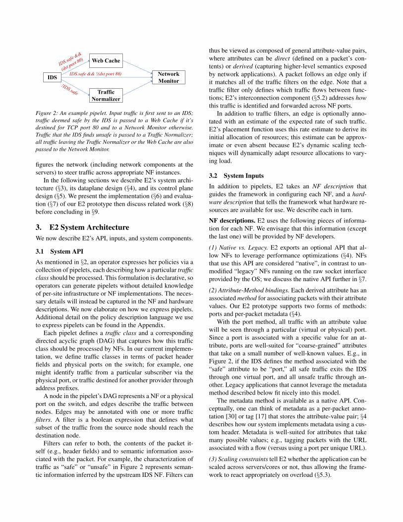
Figure 2: An example pipelet. Input traffic is first sent to an IDS;traffic deemed safe by the IDS is passed to a Web Cache if it’sdestined for TCP port 80 and to a Network Monitor otherwise.Traffic that the IDS finds unsafe is passed to a Traffic Normalizer;all traffic leaving the Traffic Normalizer or the Web Cache are alsopassed to the Network Monitor.
figures the network (including network components at theservers) to steer traffic across appropriate NF instances.
In the following sections we describe E2’s system archi-tecture (§3), its dataplane design (§4), and its control planedesign (§5). We present the implementation (§6) and evalua-tion (§7) of our E2 prototype then discuss related work (§8)before concluding in §9.
3. E2 System ArchitectureWe now describe E2’s API, inputs, and system components.
3.1 System APIAs mentioned in §2, an operator expresses her policies via acollection of pipelets, each describing how a particular trafficclass should be processed. This formulation is declarative, sooperators can generate pipelets without detailed knowledgeof per-site infrastructure or NF implementations. The neces-sary details will instead be captured in the NF and hardwaredescriptions. We now elaborate on how we express pipelets.Additional detail on the policy description language we useto express pipelets can be found in the Appendix.
Each pipelet defines a traffic class and a correspondingdirected acyclic graph (DAG) that captures how this trafficclass should be processed by NFs. In our current implemen-tation, we define traffic classes in terms of packet headerfields and physical ports on the switch; for example, onemight identify traffic from a particular subscriber via thephysical port, or traffic destined for another provider throughaddress prefixes.
A node in the pipelet’s DAG represents a NF or a physicalport on the switch, and edges describe the traffic betweennodes. Edges may be annotated with one or more trafficfilters. A filter is a boolean expression that defines whatsubset of the traffic from the source node should reach thedestination node.
Filters can refer to both, the contents of the packet it-self (e.g., header fields) and to semantic information asso-ciated with the packet. For example, the characterization oftraffic as “safe” or “unsafe” in Figure 2 represents seman-tic information inferred by the upstream IDS NF. Filters can
thus be viewed as composed of general attribute-value pairs,where attributes can be direct (defined on a packet’s con-tents) or derived (capturing higher-level semantics exposedby network applications). A packet follows an edge only ifit matches all of the traffic filters on the edge. Note that atraffic filter only defines which traffic flows between func-tions; E2’s interconnection component (§5.2) addresses howthis traffic is identified and forwarded across NF ports.
In addition to traffic filters, an edge is optionally anno-tated with an estimate of the expected rate of such traffic.E2’s placement function uses this rate estimate to derive itsinitial allocation of resources; this estimate can be approx-imate or even absent because E2’s dynamic scaling tech-niques will dynamically adapt resource allocations to vary-ing load.
3.2 System InputsIn addition to pipelets, E2 takes an NF description thatguides the framework in configuring each NF, and a hard-ware description that tells the framework what hardware re-sources are available for use. We describe each in turn.
NF descriptions. E2 uses the following pieces of informa-tion for each NF. We envisage that this information (exceptthe last one) will be provided by NF developers.
(1) Native vs. Legacy. E2 exports an optional API that al-low NFs to leverage performance optimizations (§4). NFsthat use this API are considered “native”, in contrast to un-modified “legacy” NFs running on the raw socket interfaceprovided by the OS; we discuss the native API further in §7.
(2) Attribute-Method bindings. Each derived attribute has anassociated method for associating packets with their attributevalues. Our E2 prototype supports two forms of methods:ports and per-packet metadata (§4).
With the port method, all traffic with an attribute valuewill be seen through a particular (virtual or physical) port.Since a port is associated with a specific value for an at-tribute, ports are well-suited for “coarse-grained” attributesthat take on a small number of well-known values. E.g., inFigure 2, if the IDS defines the method associated with the“safe” attribute to be “port,” all safe traffic exits the IDSthrough one virtual port, and all unsafe traffic through an-other. Legacy applications that cannot leverage the metadatamethod described below fit nicely into this model.
The metadata method is available as a native API. Con-ceptually, one can think of metadata as a per-packet anno-tation [30] or tag [17] that stores the attribute-value pair; §4describes how our system implements metadata using a cus-tom header. Metadata is well-suited for attributes that takemany possible values; e.g., tagging packets with the URLassociated with a flow (versus using a port per unique URL).
(3) Scaling constraints tell E2 whether the application can bescaled across servers/cores or not, thus allowing the frame-work to react appropriately on overload (§5.3).

1) 1)
(�'6ZLWFK 6HUYHU�$JHQW
(��0DQDJHU
1)� «0RQLWRULQJ�
5XOH�XSGDWH�����1)�FUHDWLRQ
Figure 3: The overall E2 system architecture.
(4) Affinity constraints. For NFs that scale across servers,the affinity constraints tell the framework how to split traf-fic across NF instances. Many NFs perform stateful opera-tions on individual flows and flow aggregates. The affinityconstraints define the traffic aggregates the NF acts on (e.g.,“all packets with a particular TCP port,” or “all packets ina flow”), and the framework ensures that packets belongingto the same aggregate are consistently delivered to the sameNF instance. Our prototype accepts affinity constraints de-fined in terms of the 5-tuple with wildcards.
(5) NF performance. This is an estimate of the per-core, per-GHz traffic rate that the NF can sustain2. This is optionalinformation that E2’s placement function uses to derive acloser-to-target initial allocation of cores per NF.
Hardware description. In our current prototype, the hard-ware constraints that E2 considers when making operationaldecisions include: (1) the number of cores (and speed) andthe network I/O bandwidth per server, (2) the number ofswitch ports, (3) the number of entries in the switch flow ta-ble, and (4) the set of available switch actions. Our hardwaredescription thus includes this information. We leave to fu-ture work the question of whether and how to exploit richermodels – e.g., that consider resources such as the memoryor CPU cache at servers, availability of GPUs or specializedaccelerators [24], programmable switches [15], and so forth.
3.3 System ComponentsFigure 3 shows the three main system components in E2:the E2 Manager orchestrates overall operation of the cluster,a Server Agent manages operation within each server, andthe E2 Dataplane (E2D) acts as a software traffic processinglayer that underlies the NFs at each server. The E2 Managerinterfaces with the hardware switch(es) through standardswitch APIs [6, 14, 36] and with the Server Agents.
4. The E2 Dataplane, E2DIn the following subsections we describe the design of the E2Dataplane (E2D). The goal of E2D is to provide flexible yetefficient “plumbing” across the NF instances in the pGraph.
2Since the performance of NFs vary based on server hardware andtraffic characteristics, we expect these estimates will be provided by thenetwork operator (based on profiling the NF in their environment) ratherthan by the NF vendor.
4.1 RationaleOur E2D implementation is based on SoftNIC [23], a high-performance, programmable software switch that allows ar-bitrary packet processing modules to be dynamically config-ured as a data flow graph, in a similar manner to the Clickmodular router [30].
While the Click-style approach is widely used in variousacademic and commercial contexts, the de-facto approachto traffic management on servers uses the Open vSwitch(OVS) and the OpenFlow interface it exports. OVS is builton the abstraction of a conventional hardware switch: it isinternally organized as a pipeline of tables that store ‘match-action’ rules with matches defined on packet header fieldsplus some limited support for counters and internal state.Given the widespread adoption of OVS, it is reasonable toask why we adopt a different approach. In a nutshell, it isbecause NFV does not share many of the design considera-tions that (at least historically) have driven the architectureof OVS/Openflow and hence the latter may be unnecessarilyrestrictive or even at odds with our needs.
More specifically, OVS evolved to support “networkvirtualization platforms” (NVPs) in multi-tenant datacen-ters [31]. Datacenter operators use NVPs to create multiplevirtual networks, each with independent topologies and ad-dressing architectures, over the same physical network; thisenables (for example) tenants to ‘cut-paste’ a network con-figuration from their local enterprise to a cloud environment.The primary operation that NVPs require on the dataplaneis the emulation of a packet’s traversal through a series ofswitches in the virtual topology, and thus OVS has focusedon fast lookups on OpenFlow tables; e.g., using multiple lay-ers of caching internally [39] and limited actions.
NFV does not face this challenge. Instead, since mostcycles will likely be consumed in NFs, we are more inter-ested in performance optimizations that improve the effi-ciency of NFs (e.g., our native APIs below). Thus, ratherthan work to adapt OVS to NFV contexts, we chose to ex-plore a Click-inspired dataflow design more suited to ourneeds. This choice allowed us to easily implement variousperformance optimizations (§7) and functions in support ofdynamic scaling (§5.3) and service interconnection (§5.2).
4.2 SoftNICSoftNIC exposes virtual NIC ports (vports) to NF instances;vports virtualize the hardware NIC ports (pports) for vir-tualized NFs. Between vports and pports, SoftNIC allowsarbitrary packet processing modules to be configured as adata flow graph, in a manner similar to the Click modularrouter [30]. This modularity and extensibility differentiateSoftNIC from OVS, where expressiveness and functionalityare limited by the flow-table semantics and predefined ac-tions of OpenFlow.
SoftNIC achieves high performance by building on recenttechniques for efficient software packet processing. Specifi-

cally: SoftNIC uses Intel DPDK [27] for low-overhead I/O tohardware NICs and uses pervasive batch processing withinthe pipeline to amortize per-packet processing costs. In ad-dition, SoftNIC runs on a small number of dedicated pro-cessor cores for high throughput (by better utilizing theCPU cache) and sub-microsecond latency/jitter (by elimi-nating context switching cost). The SoftNIC core(s) con-tinuously polls each physical and virtual port for packets.Packets are processed from one NF to another using a push-to-completion model; once a packet is read from a port, itis run through a series of modules (e.g. classification, ratelimiting, etc.) until it reaches a destination port.
In our experiments with the E2 prototype (§7), we dedi-cate only one core to E2D/SoftNIC as we find a single corewas sufficient to handle the network capacity of our testbed;[23] demonstrates SoftNIC’s scalability to 40 Gbps per core.
4.3 Extending SoftNIC for E2DWe extend SoftNIC in the following three ways. First, weimplement a number of modules tailored for E2D includ-ing modules for load monitoring, flow tracking, load balanc-ing, packet classification, and tunneling across NFs. Thesemodules are utilized to implement E2’s components for NFplacement, interconnection, and dynamic scaling, as will bediscussed in the rest of this paper.
Second, as mentioned earlier, E2D provides a native APIthat NFs can leverage to achieve better system-wide perfor-mance and modularity. This native API provides support for:zero-copy packet transfer over vports for high throughputcommunication between E2D and NFs, and rich message ab-stractions which allow NFs to go beyond traditional packet-based communication. Examples of rich messages include:(i) reconstructed TCP bytestreams (to avoid the redundantoverhead at each NF), (ii) per-packet metadata tags that ac-company the packet even across NF boundaries, and (iii)inter-NF signals (e.g., a notification to block traffic from anIPS to a firewall).
The richer cross-NF communication enables not only var-ious performance optimizations but also better NF design byallowing modular functions – rather than full-blown NFs–from different vendors to be combined and reused in a flex-ible yet efficient manner. We discuss and evaluate the nativeAPI further in §7.
Lastly, E2D extends SoftNIC with a control API exposedto E2’s Server Agent, allowing it to: (i) dynamically cre-ate/destroy vports for NF instances, (ii) add/remove modulesin E2D’s packet processing pipeline, stitching NFs togetherboth within and across servers, and (iii) receive notificationsof NF overload or failure from the E2D (potentially trigger-ing scaling or recovery mechanisms).
5. The E2 Control PlaneThe E2 control plane is in charge of (i) placement (instan-tiating the pipelets on servers), (ii) interconnection (setting
(a) Original pGraph (b) iGraph with split NF B
(c) iGraph with split NF A and B (d) Optimized iGraph
A B A
B
B
B
B
A
A
A
A
B
B
A
A
A
A
B
B
Figure 4: Transformations of a pGraph (a) into an iGraph (b, c, d).
up and configuring the interconnections between NFs), (iii)scaling (dynamically adapting the placement decisions de-pending on load variations), and (iv) ensuring affinity con-straints of NFs.
5.1 NF PlacementThe initial placement of NFs involves five steps:
Step 1: Merging pipelets into a single policy graph. E2first combines the set of input pipelets into a single policygraph, or pGraph; the pGraph is simply the union of theindividual pipelets with one node for each NF and edgescopied from the individual pipelets.
Step 2: Sizing. Next, E2 uses the initial estimate of theload on a NF (sum of all incoming traffic streams), andits per-core capacity from the NF description, to determinehow many instances (running on separate cores) should beallocated to it. The load and capacity estimates need not beaccurate; our goal is merely to find a reasonable startingpoint for system bootstrapping. Dynamically adapting toactual load is discussed later in this section.
Step 3: Converting the pGraph to an iGraph. This steptransforms the pGraph into the “instance” graph, or iGraph,in which each node represents an instance of a NF. Split-ting a node involves rewiring its input and output edges andFigure 4 shows some possible cases. In the general case, asshown in Figure 4(b) and 4(c), splitting a node requires dis-tributing the input traffic across all its instances in a mannerthat respects all affinity constraints and generating the cor-responding edge filters. As an example, NF B in Figure 4(b)might require traffic with the same 5-tuple go to the sameinstance, hence E2 inserts a filter that hashes traffic from Aon the 5-tuple and splits it evenly towards B’s instances.
When splitting multiple adjacent nodes, the affinity con-straints may permit optimizations in the distribute stages, asdepicted in Figure 4(d). In this case, node B from the pre-vious example is preceded by node A that groups traffic bysource IP addresses. If the affinity constraint for A already

satisfies the affinity constraint for B, E2 does not need to re-classify the outputs from A’s instances, and instead can cre-ate direct connections as in Figure 4(d). By minimizing thenumber of edges between NF instances, instance placementbecomes more efficient, as we explain below.
Step 4: Instance placement. The next step is to map eachNF instance to a particular server. The goal is to minimizeinter-server traffic for two reasons: (i) software forward-ing within a single server incurs lower delay and consumesfewer processor cycles than going through the NICs [19, 43]and (ii) the link bandwidth between servers and the switchis a limited resource. Hence, we treat instance placement asan optimization problem to minimize the amount of traffictraversing the switch. This can be modeled as a graph par-tition problem which is NP-hard and hence we resort to aniterative local searching algorithm, in a modified form of theclassic Kernighan-Lin heuristic [28].
The algorithm works as follows: we begin with a validsolution that is obtained by bin-packing vertices into parti-tions (servers) based on a depth-first search on the iGraph;then in each iteration, we swap a pair of vertices from twodifferent partitions. The pair selected for a swap is the onethat leads to the greatest reduction in cross-partition traffic.These iterations continue until no further improvement canbe made. This provides an initial placement of NF instancesin O(n2 lg n) time where n is the number of NF instances.
In addition, we must consider incremental placement asNF instances are added to the iGraph. While the above al-gorithm is already incremental in nature, our strategy of mi-gration avoidance (§5.4) imposes that we do not swap anexisting NF instance with a new one. Hence, the incrementalplacement is much simpler: we consider all possible parti-tions where the new instance may be placed, and choose theone that will incur the least cross-partition traffic by simplyenumerating all the neighboring instances of the new NF in-stance. Thus the complexity of our incremental placementalgorithm is O(n), where n is the number of NF instances.
Step 5: Offloading to the hardware switch. Today’s com-modity switch ASICs implement various low-level fea-tures, such as L2/L3-forwarding, VLAN/tunneling, and QoSpacket scheduling. This opens the possibility of offloadingthese functions to hardware when they appear on the pol-icy graph, similar to Dragonet [48] which offloads functionsfrom the end-host network stack to NIC hardware). On theother hand, offloading requires that traffic traverse physicallinks and consume other hardware resources (table entries,switch ports, queues) that are also limited, so offloading isnot always possible. To reduce complexity in the placementdecisions, E2 uses an opportunistic approach: a NF is con-sidered as a candidate for offloading to the switch only if,at the end of the placement, that NFs is adjacent to a switchport, and the switch has available resources to run it. E2 doesnot preclude the use of specialized hardware accelerators to
IDSsafe, l4port ≠ 80
(a) Part of iGraph
IDS
(b) Instantiating vports
output vport
IDS
(c) Adding traffic classifiers
E2D classifier
Figure 5: E2 converts edge annotations on an iGraph (a) intooutput ports (b) that the applications write to, and then adds trafficfilters that the E2D implements (c).
implement NFs, though we have not explored the issue inthe current prototype.
5.2 Service InterconnectionRecall that edges in the pGraph (and by extension, iGraph)are annotated with filters. Service interconnection uses theseannotations to steer traffic between NF instances in threestages.
Instantiating NFs’ ports. The NF description specifies howmany output ports are used by a NF and which trafficattributes are associated with each port. E2D instantiatesvports accordingly as per the NF description and the iGraph.For example, Fig. 5(b) shows an IDS instance with twovports, which output “safe” and “unsafe” traffic respectively.
Adding traffic filters. An edge may require (as specified bythe edge’s filters) only a subset of the traffic generated by theNF instance it is attached to. In this case, E2 will insert anadditional classification stage, implemented by the E2D, toensure that the edge only receives traffic matching the edgefilters. Figure 5(c) illustrates an example where “safe” traf-fic is further classified based on the destination port number.While E2’s classifier currently implements BPF filtering [35]on packet header fields and metadata tags, we note that itcan be extended beyond traditional filtering to (for example)filter packets based on CPU utilization or the active/standbystatus of NF instances. To disambiguate traffic leaving ‘man-gling’ NFs that rewrite key header fields (e.g., NAT), theE2D layer dynamically creates disambiguating packet steer-ing rules based on the remaining header fields. 3
Configuring the switch and the E2D. After these steps,E2 must configure the switch and E2D to attach NF portsto edges and instantiate the necessary filters. Edges that arelocal to one server are implemented by the E2D alone. Edgesbetween servers also flow through the E2D which routesthem to physical NICs, possibly using tunneling to multiplexseveral edges into available NICs. Packet encapsulation fortunneling does not cause MTU issues, as commodity NICsand switches already support jumbo frames.
3Our approach to handling mangling NFs is enabled by the ability toinject code inline in the E2D layer. This allows us to avoid the complexityand inefficiency of solutions based on legacy virtual switches such as OVS;these prior solutions involve creating multiple instances of the manglingNF, one for each downstream path in the policy graph [20] and invoke thecentral controller for each new flow arrival [17, 20].

5.3 Dynamic ScalingThe initial placement decisions are based on estimates oftraffic and per-core performance, both of which are imper-fect and may change over time. Hence, we need solutionsfor dynamically scaling in the face of changing loads; inparticular we must find ways to split the load over severalNF instances when a single instance is no longer sufficient.We do not present the methods for contraction when under-loaded, but these are similar in spirit. We provide hooks forNFs to report on their instantaneous load, and the E2D itselfdetects overloads based on queues and processing delays.
We say we split an instance when we redistribute its loadto two or more instances (one of which is the previous in-stance) in response to an overload. This involves placing thenew instances, setting up new interconnection state (as de-scribed previously in this section), and must consider theaffinity requirements of flows (discussed later in this sec-tion), so it is not to be done lightly.
To implement splitting, when a node signals overloadthe Server Agent notifies the E2 Manager, which uses theincremental algorithm described in §5.1 to place the NFinstances. The remaining step is to correctly split incomingtraffic across the new and old instances; we address this next.
5.4 Migration Avoidance for Flow AffinityMost middleboxes are stateful and require affinity, wheretraffic for a given flow must reach the instance that holdsthat flow’s state. In such cases, splitting a NF’s instance(and correspondingly, input traffic) requires extra measuresto preserve affinity.
Prior solutions that maintain affinity either depend onstate migration techniques (moving the relevant state fromone instance to another), which is both expensive and in-compatible with legacy applications [21], or require largerule sets in hardware switches [41]; we discuss these solu-tions later in §7.
We instead develop a novel migration avoidance strategyin which the hardware and software switch act in concert tomaintain affinity. Our scheme does not require state migra-tion, is designed to minimize the number of flow table entriesused on the hardware switch to pass traffic to NF instances,and is based on the following assumptions:
• each flow f can be mapped (for instance, through a hashfunction applied to relevant header fields) to a flow IDH(f), defined as an integer in the interval R = [0, 2N );
• the hardware switch can compute the flow ID, and canmatch arbitrary ranges in R with a modest numberof rules. Even TCAM-based switches, without a nativerange filter, require fewer than 2N rules for this;
• each NF instance is associated with one subrange of theinterval R;
Switch'
E2D'
A'
E2D'
Switch'
E2D'
A'
E2D'
Switch'
E2D'
A'
E2D'
A’' A’'
(a) (b) (c)
Figure 6: (a) Flows enter a single NF instance. (b) Migrationavoidance partitions the range of Flow IDs and punts new flowsto a new replica using the E2D. Existing flows are routed to thesame instance. (c) Once enough flows expire, E2 installs steeringrules in the switch.
• the E2D on each server can track individual, active flowsthat each NF is currently handling. 4 We call F
old
(A) thecurrent set of flows handled by some NF A.
When an iGraph is initially mapped onto E2, each NF in-stance A may have a corresponding range filter [X,Y ) ! Ainstalled in the E2D layer or in the hardware switch. Whensplitting A into A and A’, we must partition the range [X,Y ),but keep sending flows in F
old
(A) to A until they naturallyterminate.
Strawman approach. This can be achieved by replacing thefilter [X,Y ) ! A with two filters
[X,M) ! A, [M,Y ) ! A0
and higher priority filters (“exceptions”) to preserve affinity:
8f : f 2 Fold
(A) ^H(f) 2 [M,Y ) : f ! A
The number of exceptions can be very large. If the switch hassmall filtering tables (hardware switches typically have onlya few thousand entries), we can reduce the range [M,Y )to keep the number of exceptions small, but this causes anuneven traffic split. This problem arises when the filters mustbe installed on a hardware switch, and A and A’ reside ondifferent servers.
Our solution To handle this case efficiently, our migrationavoidance algorithm uses the following strategy (illustratedin Figure 6) :
• Opon splitting, the range filter [X,Y ) on the hardwareswitch is initially unchanged, and the new filters (twonew ranges plus exceptions) are installed in the E2D ofthe server that hosts A;
• As flows in Fold
(A) gradually terminate, the correspond-ing exception rules can be removed;
• When the number of exceptions drops below somethreshold, the new ranges and remaining exceptionsare pushed to the switch, replacing the original rule[X,Y ) ! A.
4The NF description indicates how to aggregate traffic into flows (i.e.,the same subset of header fields used to compute the flow ID).

By temporarily leveraging the capabilities of the E2D, mi-gration avoidance achieves load distribution without thecomplexity of state migration and with efficient use ofswitch resources. The trade-off is the additional latency tonew flows being punted between servers (but this overheadis small and for a short period of time) and some additionalswitch bandwidth (again, for a short duration) – we quantifythese overheads in §7.
6. Prototype ImplementationOur E2 implementation consists of the E2 Manager, theServer Agent, and the E2D. The E2 Manager is implementedin F# and connects to the switch and each server using anout-of-band control network. It interfaces with the switchvia an OpenFlow-like API to program the flow table, whichis used to load balance traffic and route packets betweenservers. The E2 Manager runs our placement algorithm (§5)and accordingly allocates a subset of nodes (i.e., NF in-stances) from the iGraph to each server and instructs theServer Agent to allocate cores for the NFs it has been as-signed, to execute the the NFs, to interface with the E2Dto allocate ports, create and compose processing modules inSoftNIC, and to set up paths between NFs.
The Server Agent is implemented in Python and runs as aPython daemon on each server in the E2 cluster. The ServerAgent acts as a shim layer between the E2 Manager and itslocal E2D, and it simply executes the instructions passed bythe E2 Manager.
The E2D is built on SoftNIC (§4). Our E2D contains sev-eral SoftNIC modules which the Server Agent configures forservice interconnection and load balancing. Specifically, wehave implemented a match/action module for packet meta-data, a module for tagging and untagging packets with tun-neling headers to route between servers, and a steering mod-ule which implements E2D’s part in migration avoidance.The E2D implements the native API discussed in §4.3; forlegacy NFs, E2D creates regular Linux network devices.
7. EvaluationPrototype. Our E2 prototype uses an Intel FM6000 SeacliffTrail Switch with 48 10 Gbps ports and 2,048 flow tableentries. We connect four servers to the switch, each with one10 Gbps link. One server uses the Intel Xeon E5-2680 v2CPU with 10 cores in each of 2 sockets and the remaininguse the Intel Xeon E5-2650 v2 CPU with 8 cores in eachof 2 sockets, for a total of 68 cores running at 2.6 GHz. Oneach server, we dedicate one core to run the E2D layer. TheE2 Manager runs on a standalone server that connects toeach server and to the management port of the switch ona separate 1 Gbps control network.
We start with microbenchmarks that evaluate E2’s dataplane (§7.1), then evaluate E2’s control plane techniques(§7.2) and finally evaluate overall system performance withE2 (§7.3).
Experimental Setup. We evaluate our design choices usingthe above E2 prototype. We connect a traffic generator toexternal ports on our switch with four 10 G links. We usea server with four 10G NICs and two Intel Xeon E5-2680v2 CPUs as a traffic generator. We implemented the trafficgenerator to act as the traffic source and sink. Unless statedotherwise, we present results for a traffic workload of allminimum-sized 60B Ethernet packets.
7.1 E2D: Data Plane PerformanceWe show that E2D introduces little overhead and that itsnative APIs enable valuable performance improvements.
E2D Overhead. We evaluate the overhead that E2D intro-duces with a simple forwarding test, where packets are gen-erated by an NF and ‘looped back’ by the switch to the sameNF. In this setup, packets traverse the E2D layer twice (NF! switch and switch!NF directions). We record an aver-age latency of 4.91 µs.
We compare this result with a scenario where the NF isdirectly implemented with DPDK (recall that SoftNIC andhence E2D build on top of DPDK), in order to rule outthe overhead of E2D. In this case the average latency was4.61 µs, indicating that E2D incurs 0.3 µs delay (or 0.15 µsfor each direction). Given that a typical end-to-end latencyrequirement within a CO is 1 ms5, we believe that this la-tency overhead is insignificant.
In terms of throughput, forwarding through E2D on asingle core fully saturates the server’s 10 Gbps link as ex-pected [23, 27].
The low latency and high throughput that E2D achievesis thanks to its use of SoftNIC/DPDK. Our results merelyshow that the baseline overhead that E2D/SoftNIC addsto its underlying DPDK is minimal; more complex packetprocessing at NFs would, of course, result in proportionallyhigher delays and lower throughput.
E2D Native API. Recall that E2’s native API enables per-formance optimizations through its support for zero-copyvports and rich messages. We use the latter to implementtwo optimizations: (i) bytestream vports that allow the costof TCP session reconstruction to be amortized across NFsand, (ii) packet metadata tags that eliminate redundant workby allowing semantic information computed by one NF tobe shared with the E2D or other NFs. We now quantify theperformance benefits due to these optimizations: zero-copyvports, bytestream vports, metadata.Zero-copy vports. We measure the latency and throughputbetween two NFs on a single server (since the native APIdoes nothing to optimize communication between servers).Table 1 compares the average latency and throughput of thelegacy and native APIs along this NF ! E2D ! NF path.We see that our native API reduces the latency of NF-to-NF communication by over 2.5x on average and increases
5From discussion with carriers and NF vendors.

PathNF ! E2D! NF
Latency(µs)
Gbps(1500B)
Mpps(64B)
Legacy API 3.2 7.437 0.929Native Zero-Copy API 1.214 187.515 15.24
Table 1: Latency and throughput between NFs on a single serverusing E2’s legacy vs. native API. Legacy NFs use the Linux rawsocket interface.
0 0.2 0.4 0.6 0.8 1 1.2 1.4 1.6
ByteStream
Library
GHz per Gb traffic
TCP SIG HTTP RE
Figure 7: Comparison of CPU cycles for three DPI NFs, withoutand with bytestream vports. Both cases use the native API.
throughput by over 26x; this improvement is largely due tozero-copy vports (§4) and the fact that legacy NFs incur OS-induced overheads due to packet copies and interrupts. Ournative APIs matches the performance of frameworks such asDPDK [27] and netmap [42].Bytestream vports. TCP session reconstruction, which in-volves packet parsing, flow state tracking, and TCP seg-ment reassembly, is a common operation required by mostDPI-based NFs. Hence, when there are multiple DPI NFsin a pipeline, repeatedly performing TCP reconstruction canwaste processing cycles.
We evaluate the performance benefits of bytestreamvports using a pipeline of three simple DPI NFs: (i) SIGimplements signature matching with the Aho-Corasickalgorithm, (ii) HTTP implements an HTTP parser, and(iii) RE implements redundancy elimination using Rabinfingerprinting. These represent an IDS, URL-based filtering,and a WAN optimizer, respectively. The Library case inFig. 7 represents a baseline, where each NF independentlyperforms TCP reconstruction over received packets with ourcommon TCP library. In the ByteStream case, we dedicatea separate NF (TCP) to perform TCP reconstruction andproduce metadata (TCP state changes and reassemblyanomalies) and reassembled bytestream messages for thethree downstream NFs to reuse. E2D guarantees reliabletransfer of all messages between NFs that use bytestreamvports, with much less overhead than full TCP. The resultsshow that bytestream vports can save 25% of processingcycles, for the same amount of input traffic.
Metadata Tags. Tags can carry information along with pack-ets and save repeated work in the applications; having theE2D manage tags is both a convenience and potentially alsoa performance benefit for application writers. The followingtwo experiments quantify the overhead and potential perfor-mance benefits due to tagging packets with metadata.
PathNF ! E2D! NF
Latency(µs)
Gbps(1500B)
Mpps(64B)
Header-Match 1.56 152.515 12.76Metadata-Match 1.695 145.826 11.96
Table 2: Latency and throughput between NFs on a single serverwith and without metadata tags.
0 0.1 0.2 0.3
Native API
Dedicated Classifier
GHz per Gb traffic
HTTP Parser SoftNIC Pkt XferURL Classifier E2D Match
Figure 8: Comparison of CPU cycles between using URL metadataand a dedicated HTTP parser
To measure the overhead, we measure the inter-NFthroughput using our zero-copy native API under two sce-narios. In Header-Match, the E2D simply checks a particularheader field against a configured value; no metadata tags areattached to packets. In Metadata-Match, the source NF cre-ates a metadata tag for each packet which is set to the valueof a bit field in the payload; the E2D then checks the tagagainst a configured value. Table 2 shows our results. We seethat Metadata-Match achieves a throughput of 11.96 mpps,compared to 12.7 for Header-Match. Thus adding metadatalowers throughput by 5.7%.
We demonstrate the performance benefits of metadatatags using a pipeline in which packets leaving an upstreamHTTP Logger NF are forwarded to a CDN NF based onthe value of the URL associated with their session. SinceLogger implements HTTP parsing, a native implementationof the Logger NF can tag packets with their associated URLand the E2D layer will steer packets based on this metadatafield. Without native metadata tags, we need to insert astandalone ‘URL-Classifier’ NF in the pipeline between theLogger and CDN NFs to create equivalent information. Inthis case, traffic flows as Logger! E2D ! URL-Classifier! E2D!CDN. As shown in Figure 8, the additional NFand E2D traversal (in bold) increase the processing load by41% compared to the use of native tags.
7.2 E2 Control Plane PerformanceWe now evaluate our control plane solutions for NF place-ment, interconnection, and dynamic scaling, showing thatour placement approach achieves better efficiency than twostrawmen solutions and that our migration-avoidance designis better than two natural alternatives.
NF Placement. E2 aims to maximize cluster-wide through-put by placing NFs in a manner that minimizes use of thehardware switch capacity. We evaluate this strategy by sim-ulating the maximum cluster-wide throughput that a rack-scale E2 system (i.e., with 24 servers and 24 external ports)

0 20 40 60 80
Randomized
Linear
Aggregate throughput (Gbps)
E2 Heurstic Packing Random
Figure 9: Maximum cluster throughput with different placementsolutions, with two different pGraphs.
could sustain before any component – cores, server links, orswitch capacity – of the system is saturated. We compare oursolution to two strawmen: “Random” that places nodes onservers at random, and “Packing” that greedily packs nodesonto servers while traversing the iGraph depth-first. We con-sider two iGraphs: a linear chain with 5 nodes, and a morerealistic random graph with 10 nodes.
Figure 9 shows that our approach outperforms the straw-men in all cases. We achieve 2.25-2.59⇥ higher throughputcompared to random placement; bin-packing does well ona simple chain but only achieves 0.78⇥ lower throughputfor more general graphs. Thus we see that our placementheuristic can improve the overall cluster throughput over thebaseline bin-packing algorithm.
Finally, we measure the controller’s time to computeplacements. Our controller implementation takes 14.6ms tocompute an initial placement for a 100-node iGraph and hasa response time of 1.76ms when handling 68 split requestsper second (which represents the aggressive case of one splitrequest per core per second). We conclude that a centralizedcontroller is unlikely to be a performance bottleneck in thesystem.Updating Service Interconnection. We now look at thetime the control plane takes to update interconnection paths.In our experiments, the time to update a single rule in theswitch varies between 1-8ms with an average of 3ms (thedatasheet suggests 1.8ms as the expected time); the switchAPI only supports one update at a time. In contrast, the per-rule update latency in E2D is only 20 µs, which can be fur-ther amortized with a batch of multiple rules. The relativelylong time it takes to update the hardware switch (as com-pared to the software switch) reinforces our conservative useof switch rule entries in migration avoidance. Reconfiguringthe E2D after creating a new replica takes roughly 15ms, in-cluding the time to coordinate with the E2 Manager and toinvoke a new instance.Dynamic Scaling. We start by evaluating migration avoid-ance for the simple scenario of a single NF instance thatsplits in two; the NF requires flow-level affinity. We drivethe NF with 1 Gbps of input traffic, with 2,000 new flowsarriving each second on average and flow length distribu-tions drawn from published measurement studies [32]. This
0200400600800
1,0001,200
0 5 10 15
Thro
ughp
ut (M
bps)
Time (s)
Total RateOriginalNew
Figure 10: Traffic load at the original and new NF instance withmigration avoidance; original NF splits at 2s.
012345
01020304050
0 5 10 15
Band
wid
th (G
bps)
Late
ncy
(μs)
Time (s)
Median LatencySwitch Bandwidth
Figure 11: Latency and bandwidth overheads of migration avoid-ance (the splitting phase is from 1.8s to 7.4s).
results in a total load of approximately 10,000 active concur-rent flows and hence dynamic scaling (effectively) requires‘shifting’ load equivalent to 5,000 flows off the original NF.
Fig. 10 shows the traffic load on the original and new NFinstances over time; migration avoidance is triggered closeto the 2 second mark. We see that our prototype is effectiveat balancing load: once the system converges, the imbalancein traffic load on the two instances is less than 10%.
We also look at how active flows are impacted during theprocess of splitting. Fig. 11 shows the corresponding packetlatency and switch bandwidth consumption over time. Wesee that packet latency and bandwidth consumption increaseduring the splitting phase (roughly between the two andeight second markers) as would be expected given we ‘de-tour’ traffic through the E2D layer at the original instance.However this degradation is low: in this experiment, latencyincreases by less than 10µsecs on average, while switchbandwidth increases by 0.5Gbps in the worst case, for asmall period of time; the former overhead is a fixed cost, thelatter depends on the arrival rate of new flows which is rela-tively high in our experiment. In summary: migration avoid-ance balances load evenly (within 10% of ideal) and withina reasonable time frame (shifting load equivalent to roughly5,000 flows in 5.6 seconds) and does so with minimal im-pact to active flows (adding less than 10µseconds to packetlatencies) and highly scalable use of the switch flow table.
We briefly compare to two natural strawmen. An “alwaysmigrate” approach, as explored in [41] and used in [21], mi-grates half the active flows to the new NF instance. This ap-proach achieves an ideal balance of load but is complex6 and
6For example, [41] reroutes traffic to an SDN controller while migra-tion is in progress while [21] requires a two-phase commit between the

0
10
20
30
40
0
20
40
60
80
0 20 40 60 80 100
Thro
ughp
ut (G
bps)
CPU
(cor
es)
Time (s)
CPU Usage Optimal CPUInput Traffic Switch Traffic
Figure 12: E2 under dynamic workload.
Nat Firewall IDS VPN
Figure 13: Pipeline used for the evaluation
requires non-trivial code modifications to support surgicalmigration of per-flow state. In addition, the disruption dueto migration is non-trivial: the authors of [41] report taking5ms to migrate a single flow during which time traffic mustbe “paused”; the authors do not report performance whenmigrating more than a single flow.
A “never migrate” approach that does not leverage soft-ware switches avoids migrating flows by pushing exceptionfilters to the hardware switch. This approach is simple andavoids the overhead of detouring traffic that we incur. How-ever, this approach scales poorly; e.g., running the above ex-periment with never-migrate resulted in a 80% imbalancewhile consuming all 2,048 rules on the switch.7 Not onlywas the asymptotic result poor, but convergence was slowbecause the switch takes over 1ms to add a single rule andwe needed to add close to 2,000 rules.
7.3 E2 Whole-System PerformanceTo test overall system performance for more realistic NFworkloads, we derived a policy graph based on carrier guide-lines [7] and BNG router datasheets [4] with 4 NFs: a NAT, afirewall, an IDS and a VPN, as shown in Figure 13. All NFsare implemented in C over our zero-copy native API.
We use our prototype with the server and switch configu-ration described earlier. As in prior work on scaling middle-boxes [21], we generate traffic to match the flow-size distri-bution observed in real-world measurements [13].
We begin the experiment with an input load of 7.2 Gbpsand the optimal placement of NFs. Over the course of theexperiment, we then vary the input load dynamically up to amaximum of 12.3 Gbps and measure the CPU utilization andswitch bandwidth used by E2. Figure 12 plots this measuredCPU and switch resource consumption under varying input
controller and switches; the crux of the problem here is the need for closecoordination between traffic and state migration.
7The “always migrate” prototype in [41] also uses per-flow rules inswitches but this does not appear fundamental to their approach.
load. As points of comparison, we also plot the input trafficload (a lower bound on the switch bandwidth usage) and acomputed value of the optimal number of cores. We derivedthe optimal number of cores by summing up the optimalnumber of NF instances for each NF in the pipeline. Toderive the optimal number of NF instances for a NF, wemultiply the cycles per unit of traffic that the NF consumeswhen running in isolation by the total input traffic to the NF,then we divide it by the cycle frequency of a CPU core.
We observe that E2’s resource consumption (both CPUand switch bandwidth) scales dynamically to track the trendin input load. At its maximum scaling point, the systemconsumed up to 60 cores, running an iGraph of 56 vertices(i.e., 56 NF instances) and approximately 600 edges. Wealso observe the gap between actual vs. optimal resourceusage in terms of both CPU cores (22.7% on average) andthe switch bandwidth (16.4% on average). We note thatour measured CPU usage does include the cores dedicatedto running SoftNIC (which was always one per server inour experiments) while these cores are not included in theoptimal core count. Thus the overheads that E2 incurs appearreasonable given that our lower bounds ignore a range ofsystem overheads around forwarding packets between NFs,the NIC and the switch, as also the overheads around runningmultiple NFs on a shared core or CPU (cache effects, etc.),and the efficiencies that result from avoiding migration andincremental placement as traffic load varies. Finally, we notethat our NFs do not use our bytestream and metadata APIswhich we expect could yield further improvements.
8. Related WorkWe elaborate on related efforts beyond the work mentionedinline throughout this paper.
Industry efforts. Within industry, ETSI operates as the stan-dards body for NFV and OPNFV is a nascent open-sourceeffort with many of the same participants. While “orches-tration” figures prominently in their white papers, discus-sions with participants in these efforts revealed that fewdemonstrated solutions exist as yet. Components of E2 havebeen approved as an informative standard at ETSI to fill thisrole [10].
In terms of academic projects, there are various systems thataddress individual aspects of E2’s functionality, such as loadbalancing [18, 38], interconnection [17], declarative policies[49], migration [21, 41], but do not provide an overall frame-work and the system optimizations this enables.
End-to-end NF management. Closest to E2 is Stratos [20],an orchestration layer for NFs deployed in clouds. E2 andStratos share similar goals but differ significantly in theirdesign details. At a high level, we believe these differencesstem from E2’s decision to deviate from the canonical SDNarchitecture. In canonical SDN, the virtual switch at servers

offers only the limited processing logic associated with theOpenFlow standard. Instead, E2’s control solutions exploitthe ability to inject ‘non standard’ processing logic on thedata path and this allows us to devise simpler and morescalable solutions for tasks such as service interconnection,overload detection, and dynamic scaling.
NF interconnection. Our use of metadata tags (§3) takesinspiration from prior work on FlowTags [17] but with a fewsimplifying differences: (1) we do not require metadata toaccommodate ‘mangling’ NFs, such as NAT (a key focus in[17]); and (2) metadata tags are only declared and configuredat the time of system initialization, and at runtime the E2datapath does not require reactive involvement of the SDNcontroller on a per-flow basis, as in FlowTags. Once again,we believe these differences follow from our decision toembed rich programmability in the E2D layer. Our metadatatags are also inspired by the concept of packet annotations inClick [30] and ‘network service headers’ as defined by theIETF’s Service Function Chaining [45].
Hardware platform. E2’s platform of choice is a combina-tion of commodity servers and merchant switch silicon. TheServerSwitch system [33] and some commercial “servicerouters” and appliances [5] also combine x86 and switch-ing hardware; however, in these designs, the two are tightlyintegrated, locking operators into a fixed ratio of switchingto compute capacity. E2 is instead based on loose integra-tion: operators can mix-and-match components from dif-ferent vendors and can reconfigure (even in the field) theamount of switching and compute capacity based on theirevolving needs. Greenhalgh et al. [22] describe their visionof a “flowstream” platform that combines switch and x86hardware in a manner similar to E2 but we are unaware ofa detailed design or implementation based on the proposedplatform, nor do they articulate the need for a framework ofthe form E2 aims to provide.
Data plane components. Multiple recent efforts pro-vide specialized platforms in support of efficient softwarepacket processing. Frameworks such as DPDK [27] andnetmap [42] are well established tools for high perfor-mance packet I/O over commodity NICs. Other systemsaddress efficient packet transfer between VMs in a singleserver [19, 25, 26, 43], still others explore the trade-offs inhosting NFs in processes, containers, or VMs [29, 34]. Allthese systems address issues that are complementary but or-thogonal to E2: these systems do not address the end-to-endNFV orchestration that E2 does (e.g., placement, scaling),but E2 (and the NFs that E2 supports) can leverage ideasdeveloped in these systems for improved performance.
Dynamic scaling with cross-NF state. Our migrationavoidance scheme (§5.4) avoids the complexity of state mi-gration for NFs that operate on state that is easily partitionedor replicated across NF instances; e.g., per-flow counters,per-flow state machines and forwarding tables. However, we
do not address the consistency issues that arise when globalor aggregate state is spread across multiple NF instances.This is a difficult problem that is addressed in the Split-Merge [41] and OpenNF [21] systems. These systems re-quire that NF vendors adopt a new programming model [41]or add a non-trivial amount of code to existing NF imple-mentations [21]. To support NFs that adopt the Split-Mergeor OpenNF architecture, we could extend the E2 controllerto implement their corresponding control mechanisms.
9. ConclusionIn this paper we have presented E2, a framework for NFVpacket processing. It provides the operator with a single co-herent system for managing NFs, while relieving developersfrom having to develop per-NF solutions for placement, scal-ing, fault-tolerance, and other functionality. We hope that anopen-source framework such as E2 will enable potential NFvendors to focus on implementing interesting new NFs whilenetwork operators (and the open-source community) can fo-cus on improving the common management framework.
We verified that E2 did not impose undue overheads, andenabled flexible and efficient interconnection of NFs. Wealso demonstrated that our placement algorithm performedsubstantially better than random placement and bin-packing,and our approach to splitting NFs with affinity constraintswas superior to the competing approaches.
AcknowledgementsWe thank our shepherd, Jeff Mogul, and the anonymous re-viewers of the SOSP program committee, for their thought-ful feedback which greatly improved this paper. Ethan Jack-son, Kay Ousterhout, and Joshua Reich offered feedback onearly drafts of this paper and Maziar Manesh helped us de-fine our lab environment. We are indebted to Tom Anschutz(AT&T), Wenjing Chu (Dell), Yunsong Lu (Huawei), Chris-tian Maciocco (Intel), Pranav Mehta (Intel), Andrew Ran-dall (Metaswitch), Attila Takacs (Ericsson), Percy Tarapore(AT&T), Martin Taylor (Metaswitch) and Venky Venkatesan(Intel) for discussions on NFV efforts in industry.
Appendix: E2 Policy LanguageIn E2, the operator writes a collection of policy statements,each of which is represented as a directed acyclic graphwhich we call a ‘pipelet’. Nodes in a pipelet correspond toNetwork Functions (NFs) which receive packets on inboundedges and output packets to outbound edges. Edges are as-sociated with filters which we elaborate on shortly.
NFs are instantiated from specific application types,much like objects are instantiated from classes in object-oriented programming. In addition to user-defined NFs,there are predefined ones such as Port which denotes a porton the switch, Drop, which discards packets, and Tee whichcreates multiple copies of a packet.

// First, instantiate NFs from application types.
Proxy p;
NAT n;
FW f;
Port<0-7> int; // internal customer-facing ports
Port<8-15> ext; // external WAN-facing ports
// subnet declarations, to simplify filter writing
Address my_net 10.12.30.0/24; // private IP addr
Address wan_net 131.114.88.92/30; // public IP addr
pipelet { // outbound traffic
int [dst port 80] -> p;
int [!(dst port 80)] -> n;
p [!(dst ip my_net)] -> n;
n -> f;
f [FW.safe && !(dst ip wan_net)] -> ext;
f [!FW.safe] -> Drop;
}
pipelet { // inbound traffic
ext -> f;
f [FW.safe && (dst ip wan_net)] -> n;
n [(src port 80) && (dst ip my_net)] -> p;
n [!(src port 80) && (dst ip my_net)] -> int;
p [dst ip my_net] -> int;
}
Figure 14: An example specification of a policy. (Certain dropactions are omitted for clarity.)
Figure 14 shows an example of a policy with two pipelets,each of which represents a subset of the possible paths forforward and reverse traffic respectively. Figure 15 showsthe same example in graph form. The first five lines definethe nodes in the graph. Following this are two pipelets,each defining a graph for a specific traffic class. Within thepipelet, we list all the edges forming a policy graph for thattraffic class. An edge is described using the simple syntax:
src [filter_out] -> (bw) [filter_in] dst;
where all three annotations—filter out, bw, and filter in—are optional. Filters are boolean expressions computed overpacket header fields, physical/virtual ports, or metadata tags,and are written in the libpcap-filter syntax [11]. The fil-ter out annotations specify which packets generated from aNF should enter the edge and implicitly define the trafficclass; filter in annotations capture requirements on incom-ing traffic that are imposed by the downstream NF (examplebelow) and bw denotes the expected amount of traffic on theedge, at system bootup.
Figure 16 shows a partial example of the use of filter inannotations. Here outbound traffic is passed through a rate-limiter with two input vports; high priority traffic must ar-rive on one vport and low priority traffic on the other. Thustraffic must be filtered prior to entering the downstream NF;we use filter in annotations to capture such requirements. Inthis example, prio0 and prio1 are NF-specific metadata that,in this case, are resolved to ports vp0 and vp1 at compiletime based on information in the rate-limiter’s NF descrip-tion (see §2). In some sense, these are ‘placeholder’ metadatain that they serve as a level of indirection between policyand mechanism but may not appear at runtime. This allows
int
n
f
p
ext Drop
(a) pipelet for outbound traffic
dst port 80
!(dst ip my_net)
!(dst port 80)
FW.safe && !(dst ip wan_net) !FW.safe
ext
f
n
FW.safe && (dst ip wan_net)
int
p
!(src port 80) && (dst ip my_net)
src port 80 && dst ip my_net
dst ip my_net
(b) Pipelet for outbound traffic
Figure 15: Graphical representation of the pipelets in Figure 14.
RateLimiter r; // two input ports, vp0 and vp1
Port<0-7> int; // internal customer-facing ports
pipelet { // outbound traffic
int [tos 0] -> [prio0] r;
int [tos 1] -> [prio1] r;
r -> ...
}
Figure 16: An example of a policy that uses filter in annotations.
the operator to be agnostic to how the rate-limiter identifiesprio0 vs. prio1 traffic. For example, if this is done usingmetadata (a native rate limiter), E2 will automatically con-figure the E2D layer to add the appropriate metadata tags; ifinstead the rate-limiter offers different input ports for eachpriority class, then the E2D layer will simply steer traffic tothe appropriate vport (with no tags, as in our example).
E2 merges all pipelets into a single policy graph, termeda pGraph. During this process, E2 checks that each packetcoming from a node has exactly one destination. This is ver-ified by checking that the filters on every pair of edges com-ing out from a NF has an empty intersection, and that theunion of all filters attached to a NF’s output evaluates totrue. If a packet has more than one possible destination, E2first attempts to remedy this by adding filters to ambiguousedges, specifying the traffic class of the pipelet correspond-ing to that edge. E.g., simply merging the two pipelets inFigure 15 results in ambiguity for packets leaving the NAT.E2 will thus add a filter that limits the edge for the ‘n -> f’rule to traffic arriving from an internal port. If E2 is unableto automatically resolve ambiguity, it returns an error (thisis possible if the operator writes a malformed pipelet); E2also returns an error if a packet coming from a node has nodestination.

References[1] AT&T Domain 2.0 Vision White Paper. https:
//www.att.com/Common/about_us/pdf/AT&T%
20Domain%202.0%20Vision%20White%20Paper.pdf.
[2] Brocade Vyatta 5400 vRouter. http://www.brocade.com/products/all/network-functions-virtualization/
product-details/5400-vrouter/index.page.
[3] Ericsson SE Family. http://www.ericsson.com/
ourportfolio/products/se-family.
[4] Evolution of the Broadband Network Gateway. http://resources.alcatel-lucent.com/?cid=157553.
[5] Evolved Packet Core Solution. http://lte.alcatel-
lucent.com/locale/en_us/downloads/wp_mobile_
core_technical_innovation.pdf.
[6] Intel Ethernet Switch FM6000 Series - Software Defined Net-working. http://www.intel.com/content/dam/www/
public/us/en/documents/white-papers/ethernet-
switch-fm6000-sdn-paper.pdf.
[7] Migration to Ethernet-Based Broadband Aggregation.http://www.broadband-forum.org/technical/
download/TR-101_Issue-2.pdf.
[8] Network Functions Virtualisation. http://www.etsi.org/technologies-clusters/technologies/nfv.
[9] NFV Proofs of Concept. http://www.etsi.org/
technologies-clusters/technologies/nfv/nfv-poc.
[10] REL002: Scalable Architecture for Reliability (work inprogress). http://docbox.etsi.org/ISG/NFV/Open/
Drafts/.
[11] pcap-filter(7) FreeBSD Man Pages, Jan 2008.
[12] ANDERSON, C. J., FOSTER, N., GUHA, A., JEANNIN, J.-B., KOZEN, D., SCHLESINGER, C., AND WALKER, D.NetKAT: Semantic Foundations for Networks. In Proc. ACMPOPL (2014).
[13] BENSON, T., AKELLA, A., AND MALTZ, D. Network TrafficCharacteristics of Data Centers in the Wild. In Proc. InternetMeasurement Conference (2010).
[14] BOSSHART, P., DALY, D., IZZARD, M., MCKEOWN, N.,REXFORD, J., TALAYCO, D., VAHDAT, A., VARGHESE,G., AND WALKER, D. Programming Protocol-IndependentPacket Processors. CoRR abs/1312.1719 (2013).
[15] BOSSHART, P., GIBB, G., KIM, H.-S., VARGHESE,G., MCKEOWN, N., IZZARD, M., MUJICA, F., ANDHOROWITZ, M. Forwarding Metamorphosis: Fast Pro-grammable Match-Action Processing in Hardware for SDN.In Proc. ACM SIGCOMM (2013).
[16] CASADO, M., FREEDMAN, M. J., PETTIT, J., LUO, J.,MCKEOWN, N., AND SHENKER, S. Ethane: Taking Controlof the Enterprise. In Proc. ACM SIGCOMM (2007).
[17] FAYAZBAKHSH, S., CHIANG, L., SEKAR, V., YU, M., ANDMOGUL, J. FlowTags: Enforcing Network-Wide Policies inthe Face of Dynamic Middlebox Actions. In Proc. USENIXNSDI (2014).
[18] GANDHI, R., LIU, H. H., HU, Y. C., LU, G., PADHYE, J.,YUAN, L., AND ZHANG, M. Duet: Cloud Scale Load Balanc-
ing with Hardware and Software. In Proc. ACM SIGCOMM(2014).
[19] GARZARELLA, S., LETTIERI, G., AND RIZZO, L. VirtualDevice Passthrough for High Speed VM Networking. In Proc.ANCS (2015).
[20] GEMBER, A., KRISHNAMURTHY, A., JOHN, S. S.,GRANDL, R., GAO, X., ANAND, A., BENSON, T., AKELLA,A., AND SEKAR, V. Stratos: A Network-Aware OrchestrationLayer for Middleboxes in the Cloud. CoRR abs/1305.0209(2013).
[21] GEMBER-JACOBSON, A., VISWANATHAN, R., PRAKASH,C., GRANDL, R., KHALID, J., DAS, S., AND AKELLA, A.OpenNF: Enabling Innovation in Network Function Control.In Proc. ACM SIGCOMM (2014).
[22] GREENHALGH, A., HUICI, F., HOERDT, M., PAPADIM-ITRIOU, P., HANDLEY, M., AND MATHY, L. Flow Process-ing and the Rise of Commodity Network Hardware. ACMSIGCOMM Computer Communications Review 39, 2 (2009),20–26.
[23] HAN, S., JANG, K., PANDA, A., PALKAR, S., HAN, D.,AND RATNASAMY, S. SoftNIC: A Software NIC to AugmentHardware. UCB Technical Report No. UCB/EECS-2015-155(2015).
[24] HAN, S., JANG, K., PARK, K., AND MOON, S. Packet-Shader: a GPU-Accelerated Software Router. In Proc. ACMSIGCOMM (2010).
[25] HONDA, M., HUICI, F., LETTIERI, G., AND RIZZO, L.mSwitch: A Highly-Scalable, Modular Software Switch. InProc. SOSR (2015).
[26] HWANG, J., RAMAKRISHNAN, K. K., AND WOOD, T.NetVM: High Performance and Flexible Networking UsingVirtualization on Commodity Platforms. IEEE Transactionson Network and Service Management 12, 1 (2015), 34–47.
[27] Intel Data Plane Development Kit. http://dpdk.org.
[28] KERNIGHAN, B., AND LIN, S. An Efficient Heuristic Proce-dure for Partitioning Graphs. Bell System Technical Journal49, 2 (February 1970).
[29] KIVITY, A., LAOR, D., COSTA, G., ENBERG, P., HAR’EL,N., MARTI, D., AND ZOLOTAROV, V. OSv—Optimizing theOperating System for Virtual Machines. In Proc. USENIXATC (2014).
[30] KOHLER, E., MORRIS, R., CHEN, B., JANNOTTI, J., ANDKAASHOEK, M. F. The Click Modular Router. ACM Trans-actions on Computer Systems 18, 3 (August 2000), 263–297.
[31] KOPONEN, T., AMIDON, K., BALLAND, P., CASADO, M.,CHANDA, A., FULTON, B., GANICHEV, I., GROSS, J., IN-GRAM, P., JACKSON, E., LAMBETH, A., LENGLET, R., LI,S.-H., PADMANABHAN, A., PETTIT, J., PFAFF, B., RA-MANATHAN, R., SHENKER, S., SHIEH, A., STRIBLING, J.,THAKKAR, P., WENDLANDT, D., YIP, A., AND ZHANG, R.Network Virtualization in Multi-tenant Datacenters. In Proc.USENIX NSDI (2014).
[32] LEE, D., AND BROWNLEE, N. Passive Measurement ofOne-way and Two-way Flow Lifetimes. ACM SIGCOMMComputer Communications Review 37, 3 (November 2007).
[33] LU, G., GUO, C., LI, Y., ZHOU, Z., YUAN, T., WU, H.,XIONG, Y., GAO, R., AND ZHANG, Y. ServerSwitch: A Pro-grammable and High Performance Platform for Data CenterNetworks. In Proc. USENIX NSDI (2011).
[34] MARTINS, J., AHMED, M., RAICIU, C., OLTEANU, V.,HONDA, M., BIFULCO, R., AND HUICI, F. ClickOS andthe Art of Network Function Virtualization. In Proc. USENIXNSDI (2014).
[35] MCCANNE, S., AND JACOBSON, V. The BSD Packet Filter:A New Architecture for User-level Packet Capture. In Proc.USENIX Winter (1993).
[36] MCKEOWN, N., ANDERSON, T., BALAKRISHNAN, H.,PARULKAR, G., PETERSON, L., REXFORD, J., SHENKER,S., AND TURNER, J. OpenFlow: Enabling Innovation inCampus Networks. ACM SIGCOMM Computer Communi-cations Review 38, 2 (2008), 69–74.
[37] MONSANTO, C., REICH, J., FOSTER, N., REXFORD, J.,AND WALKER, D. Composing Software-Defined Networks.In Proc. USENIX NSDI (2013).
[38] PATEL, P., BANSAL, D., YUAN, L., MURTHY, A., GREEN-BERG, A., MALTZ, D. A., KERN, R., KUMAR, H., ZIKOS,M., WU, H., KIM, C., AND KARRI, N. Ananta: Cloud ScaleLoad Balancing. In Proc. ACM SIGCOMM (2013).
[39] PFAFF, B., PETTIT, J., KOPONEN, T., CASADO, M., ANDSHENKER, S. Extending Networking into the VirtualizationLayer. In Proc. ACM HotNets (2009).
[40] QAZI, Z., TU, C., CHIANG, L., MIAO, R., VYAS, S., ANDYU, M. SIMPLE-fying Middlebox Policy Enforcement UsingSDN. In Proc. ACM SIGCOMM (2013).
[41] RAJAGOPALAN, S., WILLIAMS, D., JAMJOOM, H., ANDWARFIELD, A. Split/Merge: System Support for Elastic Ex-ecution in Virtual Middleboxes. In Proc. USENIX NSDI(2013).
[42] RIZZO, L. netmap: A Novel Framework for Fast Packet I/O.In Proc. USENIX ATC (2012).
[43] RIZZO, L., AND LETTIERI, G. VALE: A Switched Ethernetfor Virtual Machines. In Proc. ACM CoNEXT (2012).
[44] SEKAR, V., RATNASAMY, S., REITER, M. K., EGI, N., ANDSHI, G. The Middlebox Manifesto: Enabling Innovation inMiddlebox Deployment. In Proc. ACM HotNets (2011).
[45] Network Service Header. https://tools.ietf.org/
html/draft-quinn-nsh-00.
[46] SHERRY, J., GAO, P., BASU, S., PANDA, A., KRISH-NAMURTHY, A., MACCIOCCO, C., MANESH, M., MAR-TINS, J., RATNASAMY, S., RIZZO, L., AND SHENKER, S.Rollback-Recovery for Middleboxes. In Proc. ACM SIG-COMM (2015).
[47] SHERRY, J., HASAN, S., SCOTT, C., KRISHNAMURTHY, A.,RATNASAMY, S., AND SEKAR, V. Making MiddleboxesSomeone Else’s Problem: Network Processing as a CloudService. In Proc. ACM SIGCOMM (2012).
[48] SHINDE, P., KAUFMANN, A., ROSCOE, T., AND KAESTLE,S. We Need to Talk About NICs.
[49] SOULE, R., BASU, S., KLEINBERG, R., SIRER, E. G., ANDFOSTER, N. Managing the Network with Merlin. In Proc.ACM HotNets (2013).