E. Valtonen, Space Research Lab. April 5, 2004 Seminar in Space Physics Spring 2004 Effects on Space...
54
E. Valtonen, Space Research Lab. April 5, 2004 Seminar in Space Physics Spring 2004 Effects on Space Technology Space weather Michael J. Golightly NASA Johnson Space Center
-
Upload
malik-watson -
Category
Documents
-
view
213 -
download
0
Transcript of E. Valtonen, Space Research Lab. April 5, 2004 Seminar in Space Physics Spring 2004 Effects on Space...

E. Valtonen, Space Research Lab.April 5, 2004
Seminar in Space PhysicsSpring 2004
Effects on Space Technology
Space weather
Michael J. Golightly
NASA Johnson Space Center

E. Valtonen, Space Research Lab.April 5, 2004
Seminar in Space PhysicsSpring 2004
2
Overview of space weather effects
Lanzerotti, 2001
ESTEC, Space Environmentsand Effects Analysis Section

E. Valtonen, Space Research Lab.April 5, 2004
Seminar in Space PhysicsSpring 2004
3
Overview of space weather effects
• Ground effects
• Effects on oil drilling
• Effects on train light signals (two documented events in Sweden)

E. Valtonen, Space Research Lab.April 5, 2004
Seminar in Space PhysicsSpring 2004
4
Overview of space weather effects
• Effects on communication, navigation and positioning
• Signal “scintillation” Loss of signal lock on satellites Both single and dual frequency systems may
be affected
• The Total Electron Content (TEC) along the path of a GPS signal can introduce a positioning error ( up to 100 m)
A 7-10 km height change of the lower ionosphere can give position errors of 1-12 km

E. Valtonen, Space Research Lab.April 5, 2004
Seminar in Space PhysicsSpring 2004
5
Overview of space weather effects
• Global effects
E. Valtonen, Space Research Lab.April 5, 2004
Seminar in Space PhysicsSpring 2004
6
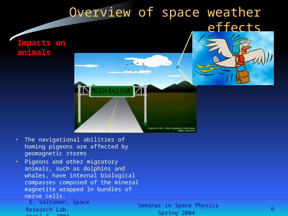
Impacts on animals
• The navigational abilities of homing pigeons are affected by geomagnetic storms
• Pigeons and other migratory animals, such as dolphins and whales, have internal biological compasses composed of the mineral magnetite wrapped in bundles of nerve cells.
Overview of space weather effects

E. Valtonen, Space Research Lab.April 5, 2004
Seminar in Space PhysicsSpring 2004
7
Overview of space weather effects
• Atmospheric drag of satellites
Increased satellite drag and loss of orbit tracking magnifies the risk of collisions with orbiting debris
In addition to loose altitude satellites can also start tumblingsince the satellites in most cases are non-symmetrical• Hubble Space Telescope drops 10-15 km per year• Skylab re-entered several years earlier than planned
• Tumbling - Low Earth Orbit (LEO) magnetic linkage between satellite and momentum transfer wheel affected by field-aligned currents during substorms & other dynamic events.

E. Valtonen, Space Research Lab.April 5, 2004
Seminar in Space PhysicsSpring 2004
8
Overview of space weather effects
• Effects on man in space

E. Valtonen, Space Research Lab.April 5, 2004
Seminar in Space PhysicsSpring 2004
9
Overview of space weather effects
• Effects on technologies in space
Surface charging Internal charging Total ionising dose Displacement damage Single event effects Interference and background in instruments
Source Drain
Floating Gate ONOTunnel Oxide
Control Gate
VCC
Data Path
Ionizing Radiation

E. Valtonen, Space Research Lab.April 5, 2004
Seminar in Space PhysicsSpring 2004
10
Plasma effects
• Surface charging
• Plasma effects on instruments

E. Valtonen, Space Research Lab.April 5, 2004
Seminar in Space PhysicsSpring 2004
11
Surface charging
• Absolute charging: build up of high potentials on spacecraft relative to the ambient plasma fast process (microseconds) not in itself necessarily a serious concern enhances surface contamination degrading thermal properties compromises scientific missions seeking to measure properties of space
environment
• Differential charging: build up of potential differences between various parts of a spacecraft relatively slow process (minutes) because of capacitance non-uniform material properties shaded or sunlit anisotropic plasma fluxes
• Effects by discharge arcing

E. Valtonen, Space Research Lab.April 5, 2004
Seminar in Space PhysicsSpring 2004
12
Surface charging
Object placed in a plasma will charge negatively due to the greater mobility of electrons compared to ions
Current equilibrium condition: at potential V
Negative surface charge prevents eV-electrons to reach the surface Equilibrium reached when the sheath region sufficient to balance currents
due to positive and negative plasma species Spacecraft will assume a floating
potential different from the plasma Assuming a single Maxwellian
distribution for the plasma gives
V -Te in eclipse (and Te> 1 keV)
plasma
}
photoelecronssecondary electrons
backscatteredelectrons
artificial source
Ie+Ii+Ipe+Isec+Iback+Iart=0

E. Valtonen, Space Research Lab.April 5, 2004
Seminar in Space PhysicsSpring 2004
13
Surface charging At low energies (tens of eV) the secondary emission ratio exceeds unity Typically at 1-2 keV, emission ratio drops below unity charging Hot plasma (20 keV) injected from the magnetospheric tail during
substorms
Gubby and Evans, JASTP 64, 1723 (2002)
Anomalies concentrate in themidnight-morning sector.

E. Valtonen, Space Research Lab.April 5, 2004
Seminar in Space PhysicsSpring 2004
14
Surface charging
In sunlight photocurrent from a surface much higher than plasma currents: equilibrium controlled by emission and reattraction of photoelectrons by UV flux
In conditions with no sunlight and low cold plasma density (outside of the plasmasphere) surfaces can charge to very high potentials
Upon exiting eclipse various surfacematerials discharge at different rates possibility of large differential potentials
Wake effect in LEO: spacecraft velocity> ion velocity, but < electron velocity ions impact only ram surfaces, electronsall surfaces differential charging
worsens the otherwise favourable environment of high-density low-energy plasma

E. Valtonen, Space Research Lab.April 5, 2004
Seminar in Space PhysicsSpring 2004
15
Surface charging• Modeling discharge characteristics
Spacecraft in space considered as a capacitor relative to the space plasma potential Dielectroc surfaces divide the spacecraft into many capacitors The components of the system of capacitors are charged at different rates
dependent on incident fluxes, time constants, spacecraft configuration effects etc. Sophisticated computer programs needed taking into account 3-dimensional effects
NASA Charging Analyzer Program (NASCAP)
• Mitigation in design Basic geometry and grounding of surfaces Conductive surfaces Knowledge and selection of
dielectric thickness dielectric constant ( surface capacitance) dielectric resistivity (generally not a constant in space environment) surface resistivity secondary emission yields photoelectron yield

E. Valtonen, Space Research Lab.April 5, 2004
Seminar in Space PhysicsSpring 2004
16
Surface charging• Surface charging effects
Charging leads to arc-discharge process releasing large amounts of charge currents flowing in structures broad-band electromagnetic field coupling into electronics
Undesired effects due to discharge arcing currents and EMI generation dielectric breakdown (punch-through) between surfaces (flash-over)
noise in data and wiring telemetry glitches logic upsets spurious commands materials damage (sputtering, change of conductivity, darkening) attraction of chemically active materials
Examples Marecs-A, 1981, GEO, 617 anomalies in status monitoring circuits Anik E1 and E2, 1991, GEO, a large number of mode switches
Koons et al., Aerospace Report No TR-99(1670)-1:The most serious spacecraft anomalies have been caused by surface charging, including 4 out of 11 missions lost or terminated due to space weather effects

E. Valtonen, Space Research Lab.April 5, 2004
Seminar in Space PhysicsSpring 2004
17
Plasma effects on instruments
• Discharges in high-voltage circuits• High potentials in plasma instruments
Distorts energy distribution of incident ions instrument bias with respect to plasma ground
Perturbation of particle trajectories angular resolution sensitivity
High ground potentials
• Sputtering of surfaces due to considerable ion kinetic energy X-ray mirrors Contamination source
re-attraction of ionised outgassing and sputtering products Change of thermo-optical properties of thermal control surfaces
• Dust generation and shedding Startracker anomalies Infrared sensor interference

E. Valtonen, Space Research Lab.April 5, 2004
Seminar in Space PhysicsSpring 2004
18
Radiation effects
• Internal charging
• Total ionizing dose
• Displacement damage
• Single event effects
• Sensor background and interference

E. Valtonen, Space Research Lab.April 5, 2004
Seminar in Space PhysicsSpring 2004
19
Internal charging
Range in AluminiumElectrons: ESTAR
Protons: SRIM-2003
0,0001
0,001
0,01
0,1
1
10
100
1000
10000
0,01 0,1 1 10 100 1000Energy (MeV)
Ran
ge
(mm
)
ESTAR
Weber Max
SRIM-2003
Surface charging0 - 50 keV electrons
Internal chargingE > 0.1 MeV electrons
Penetration of electrons and protons through material:Electrons > a few 100 keV capable to penetrate through shielding internal charging (deep dielectric or bulk or thick charging)

E. Valtonen, Space Research Lab.April 5, 2004
Seminar in Space PhysicsSpring 2004
20
Internal charging
• Basic cause of internal charging: electrons accelerated in the magnetosphere during extended intervals of enhanced geomagntic activity
• Moderate geomagnetic storms temporarily depopulate energetic (> 50 keV) electrons at GEO wave-particle instability gross changes in the morphology of the magnetic field
precipitation
• Refilled within 1-2 days by diffusion of electrons accelerated deeper in the magnetosphere producing greatly enhanced fluxes and harder spectrum at GEO

E. Valtonen, Space Research Lab.April 5, 2004
Seminar in Space PhysicsSpring 2004
21
Internal charging
• Time-integrated flux (=fluence) important Charge builds up when charge leakage rate < charge collection rate Discharge occurs when electric field > 2x10⁵ V/cm >2 MeV electron flux >3x108 cm-2sr-1d-1 for 3 consequtive days or
>109 cm-2sr-1d-1 for a single day
• Electrons >100 keV penetrate into and are
trapped in isolated parts Highly insulating dielectrics Floating conductors
• Electrostatic discharge via Groundlines Structure
High-energy electrons
ZAP!
Wrenn and Sims, AGU Monograph no 97, 275 (1996)

E. Valtonen, Space Research Lab.April 5, 2004
Seminar in Space PhysicsSpring 2004
22
Internal charging• Local time distribution of internal charging anomalies different
from surface charging anomalies reflecting More uniform distribution of relativistic electrons Cumulative effect
• Capacitor plate equation
typermittividielectric
tyconductividielectric
timerelaxation
tJ
d
tVtE
/exp1)(
)(
J/ > dielectric strength discharge
High-density of (lower-energy) electrons (LEO) large JHigh-energy (lower-density) electrons (GEO) high V } High E

E. Valtonen, Space Research Lab.April 5, 2004
Seminar in Space PhysicsSpring 2004
23
Internal charging• Potential targets for internal charging
Dielectrics cable wrap wire insulation PCBs feed-throughs
Floating conductors PCB metallization islands
CRRES results established the importanceof internal charging as a source of anomalies
Violet & Frederickson, IEEE Trans. Nucl. Sci. 40, 1512 (1993)

E. Valtonen, Space Research Lab.April 5, 2004
Seminar in Space PhysicsSpring 2004
24
Internal charging
• Internal charging effects Discharge producing spurious signals
Electromagnetic transients coupling into electronics systems control signals in coaxial cables
• unintended logic changes• command errors• phantom commands• spurious signals
loss of synchronization degraded sensor performance damage to sensitive components connected to discharging cable
Physical damage Localised heating Breakdown of thermal coatings Ejection of surface material
Difficult to distinguish from surface charging initiated discharges Environmental parameters important (correlation with high-energy electron fluxes)
E. Valtonen, Space Research Lab.April 5, 2004
Seminar in Space PhysicsSpring 2004
25
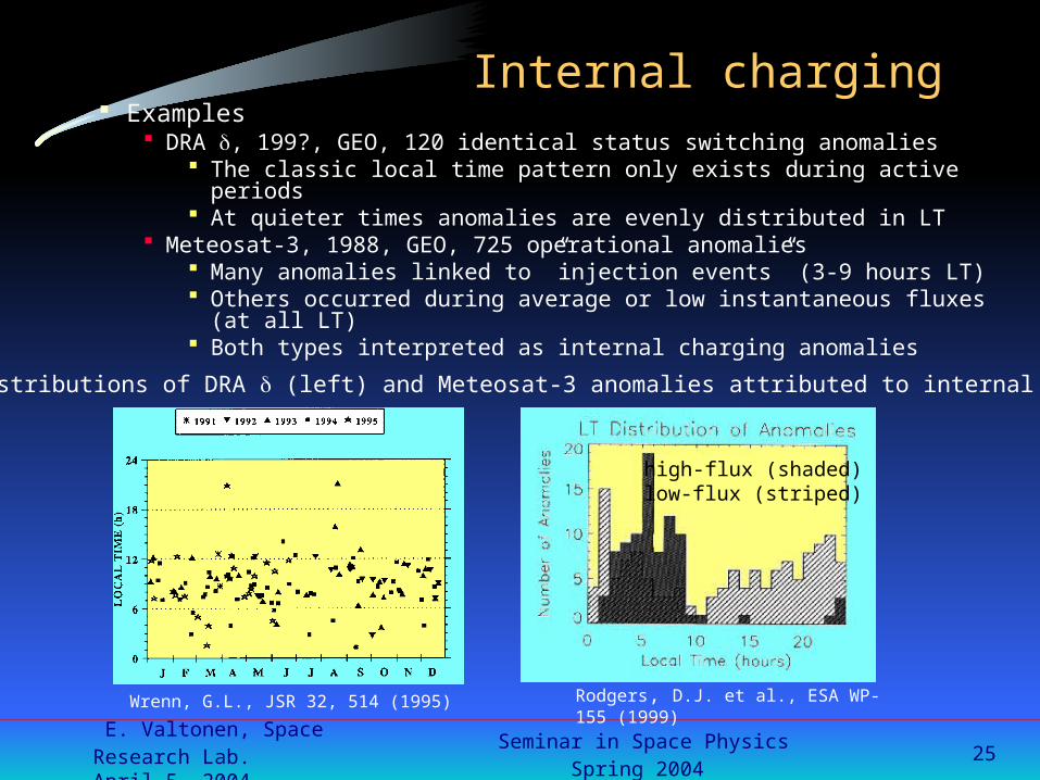
Internal charging Examples
DRA , 199?, GEO, 120 identical status switching anomalies The classic local time pattern only exists during active periods At quieter times anomalies are evenly distributed in LT
Meteosat-3, 1988, GEO, 725 operational anomalies Many anomalies linked to ”injection events” (3-9 hours LT) Others occurred during average or low instantaneous fluxes (at all LT) Both types interpreted as internal charging anomalies
Local time distributions of DRA (left) and Meteosat-3 anomalies attributed to internal charging
high-flux (shaded)low-flux (striped)
Wrenn, G.L., JSR 32, 514 (1995) Rodgers, D.J. et al., ESA WP-155 (1999)

E. Valtonen, Space Research Lab.April 5, 2004
Seminar in Space PhysicsSpring 2004
26
Internal charging• Internal charging depends on
environment shielding thickness characteristics of the charged material shape of the charged material
• Modeling object geometry environmental model (electron flux) charge deposition from an energy-range curve electric field calculation assuming temperature dependent conductivity breakdown threshold (requires test)
DERA Internal Charging Threat Assesment Tool (DICTAT)
• Mitigation proper grounding shielding leaky dielectrics EMI susceptibility reduction techniques orbit selection
E. Valtonen, Space Research Lab.April 5, 2004
Seminar in Space PhysicsSpring 2004
27
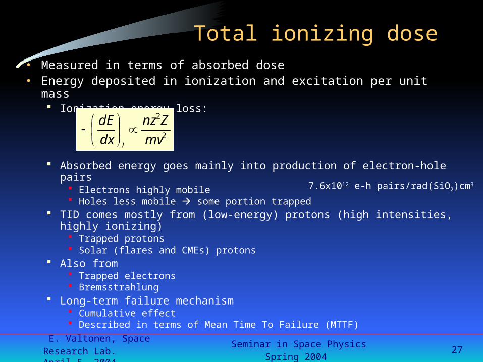
• Measured in terms of absorbed dose• Energy deposited in ionization and excitation per unit mass
Ionization energy loss:
Absorbed energy goes mainly into production of electron-hole pairs Electrons highly mobile Holes less mobile some portion trapped
TID comes mostly from (low-energy) protons (high intensities, highly ionizing) Trapped protons Solar (flares and CMEs) protons
Also from Trapped electrons Bremsstrahlung
Long-term failure mechanism Cumulative effect Described in terms of Mean Time To Failure (MTTF)
Total ionizing dose
2
2
mv
Znz
dx
dE
i
7.6x10¹² e-h pairs/rad(SiO2)cm3

E. Valtonen, Space Research Lab.April 5, 2004
Seminar in Space PhysicsSpring 2004
28
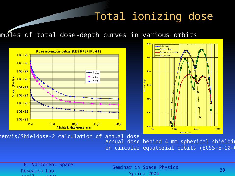
Total ionizing dose
Dose rate important Directional fluxes Depends on mission
orbit altitude and orientation duration and timing relative to the solar cycle
Basics of dose calculation:
Mission specificationRadiation environment model} compute charged-particle fluxes f(E)
Radiation transport results D(E,d)Define simple shielding geometry
calculate dose-depth curve D(d)=ΣE f(E)·D(E,d) E}
Define actual geometry and shielding materials Dose at a point
E.g., Shieldose
E. Valtonen, Space Research Lab.April 5, 2004
Seminar in Space PhysicsSpring 2004
29
Total ionizing dose
Spenvis/Shieldose-2 calculation of annual dose
Dose at various orbits (AE8/AP8+JPL-91)
1,0E+01
1,0E+02
1,0E+03
1,0E+04
1,0E+05
1,0E+06
1,0E+07
1,0E+08
1,0E+09
0,0 5,0 10,0 15,0 20,0Al shield thickness (mm)
Do
se [
Rad
(si)
]
Polar
GEO
GTO
Examples of total dose-depth curves in various orbits
Annual dose behind 4 mm spherical shieldingon circular equatorial orbits (ECSS-E-10-04A).

E. Valtonen, Space Research Lab.April 5, 2004
Seminar in Space PhysicsSpring 2004
30
Total ionizing dose
• Total ionising dose effects Caused by trapping of charge in insulators
bulk (SiO2)
recombination centres field effects
interfaces (Si-SiO2)
direct effects on the bulk Si
Static and dynamic response altered threshold voltage shifts charge carrier mobility degradation increased leakage current gain degradation change in frequency response increased power consumption
Leakage channel

E. Valtonen, Space Research Lab.April 5, 2004
Seminar in Space PhysicsSpring 2004
31
Total ionizing dose
• Other types of total dose effects Glass coloration Polymer bond breaking Luminescence
• Avoiding total dose effects Component selection Component design Control of manufacturing process Shielding Cold redundancy
• Total ionizing dose effects becoming increasingly important

E. Valtonen, Space Research Lab.April 5, 2004
Seminar in Space PhysicsSpring 2004
32
Displacement damage• Measured in terms of Non Ionizing Energy Loss (NIEL)
Small part of energy loss in a medium goes into non-ionizing processes Elastic scattering Inelastic scattering Other inelastic processes
Corresponds to the ”nuclear stopping power” in the total dE/dx Kinetic energy ternsferred to the atoms of a medium
Contributing particles protons electrons > 150 keV (secondary) neutrons
NIEL function N(E) or its normalized form
N10(E) to derive the non-ionizing dose or the10 MeV equivalent proton damage fluence
• Displacement damage is a cumulative, long-term mechanism
ECSS-E-10-04A
E E
DN EENEfForEENEfD )()()()( 10

E. Valtonen, Space Research Lab.April 5, 2004
Seminar in Space PhysicsSpring 2004
33
Displacement damage
• Lattice displacement damage due to non-ionizing energy loss Primary knock-on atom (PKA) Vacancy
Interstitial + vacancy = Frenkel pair
Energetic PKA clusters highly disordered region in the lattice
• Displacement damage mechanism Frenkel pairs extremely mobile
Recombination Those that are not recombined form stable complex defects in the lattice
divacancies Si E centres (with P impurities) Si A centres (with O impurities)

E. Valtonen, Space Research Lab.April 5, 2004
Seminar in Space PhysicsSpring 2004
34
Displacement damage
Defects give rise to states with energy levels in the Si forbidden bandgap which can lead to
Generation of e-h pairs Recombination of e-h pairs Trapping of charge carriers Compensation of donors or acceptors Tunneling of charge carriers
I.e., Change in equilibrium carrier concentration Change in minority carrier lifetime
Displacement damage effects Reduction of gain and increase of leakage current in bipolar devices Reduced efficiency of solar cells, light emitting diodes and photodetectors Degraded charge trasfer efficiency in CCDs Resolution degradation in solid state detectors
increase of leakage current change in depletion voltage
Altered optical properties
The volume leakage current increase due to defects:I/V=qni/g,g=generation lifetime
E. Valtonen, Space Research Lab.April 5, 2004
Seminar in Space PhysicsSpring 2004
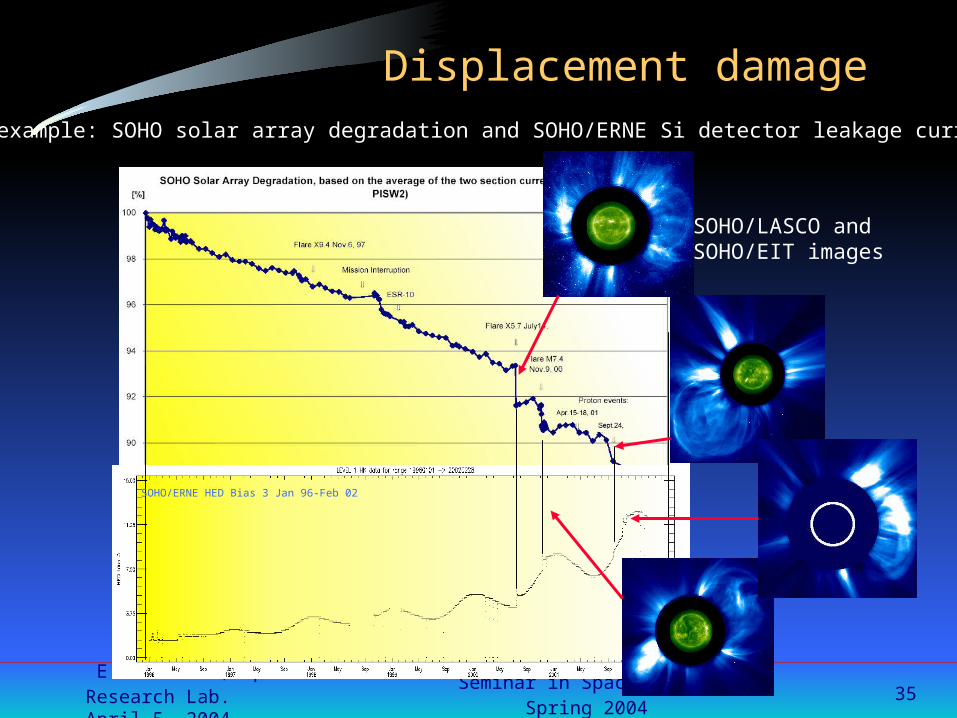
35
Displacement damageAn example: SOHO solar array degradation and SOHO/ERNE Si detector leakage current
SOHO/LASCO andSOHO/EIT images
SOHO/ERNE HED Bias 3 Jan 96-Feb 02

E. Valtonen, Space Research Lab.April 5, 2004
Seminar in Space PhysicsSpring 2004
36
Displacement damage
• Joe H. Allen, SCOSTEP
• 2000/10/23

E. Valtonen, Space Research Lab.April 5, 2004
Seminar in Space PhysicsSpring 2004
37
Single event effects
• Radiation induced observable effect in microelectronics circuits caused by a single charged particle losing energy by ionization in a small sensitive target Ionizing particle produces a conductive path through a circuit Current pulse or a continuous current path created
• Instantaneous mechanism• Expressed in terms of propability
• Many types of single event effects (SEE) SEU, SET, MBU, SEL, SEB , SEGR, SEDF, SEFI, SHE, ...
• Characterised by Linear Energy Transfer (LET)
Pickel, 1983

E. Valtonen, Space Research Lab.April 5, 2004
Seminar in Space PhysicsSpring 2004
38
Single event effects
Acronym Definition DescriptionSEU Single Event Upset Change of information storedSED Single Event Disturb Momentary disturb of information
stored in memory bitSET Single Event Transient Current transient induced by
passage of a particle, canpropagate to cause output error incombinational logic
SEDR Single Event DielectricRupture
Essentially antifuse rupture
SEGR Single Event Gate Rupture Rupture of gate dielectric causedby a high current flow
SEL Single Event Latchup High current regenerative stateinduced in 4-layer device (latchup)
SES Single Event Snapback High current regenerative stateinduced in NMOS device(snapback)
MBU Multiple Bit Upset Several memory bits upset bypassage of the same particle
SEFI Single Event FunctionalInterrupt
Corruption of control path by anupset

E. Valtonen, Space Research Lab.April 5, 2004
Seminar in Space PhysicsSpring 2004
39
Single event effects• Contributing particles
Heavy ions: (dE/dx)i z2Z/mv2
Protons through nuclear spallationreactions
• Classification of SEE Transient effects
Change of state which is non-distructive and recoverable(e.g., Single Event Upset)
Potentially catastrophic events May cause destruction unless corrected in a short time after they occur
(e.g., Single Event Latch-up) Single event hard errors (SHE)
Catastrophic failure of a single internal transistor in a complex circuit Single event functional interrup (SEFI)
SEU in control circuitry places the device into an unexpected state
E.g., Si(n,)Mg, Si(n,p)Al, Si(p,2p)Al

E. Valtonen, Space Research Lab.April 5, 2004
Seminar in Space PhysicsSpring 2004
40
Single event effects
• SEE environment characterised by Linear Energy Transfer Energy deposited in ionization per unit path length: (dE/dx)i
Integral LET spectrum Flux of particles depositing more than a certain amount of energy per unit
path length
• Devices characterised by Cross section
Effective area presented to the particles for a SEE to occur Function of LET
Critical charge Qc
Minimum charge to cause a SEE
Can be converted to critical energy (deposition) Ec
(in Si creation of an e-h pair requires 3.6 eV energy)
Critical charge for state changefor a number of Si technologies:
QC = (0.023 pC/m2)L2

E. Valtonen, Space Research Lab.April 5, 2004
Seminar in Space PhysicsSpring 2004
41
Single event effects
• LET spectrum ”Heinrich curve” combines all ions into one curve Gives the total number of particles with a given LET Ion fluxes folded by their respective energy loss curves
Fluxes of Ions F(Z,E)
LET spectrum f(L)

E. Valtonen, Space Research Lab.April 5, 2004
Seminar in Space PhysicsSpring 2004
42
Single event effects• SEU rate estimation for heavy ions (direct ionization)
Rate depends on ionization efficiency of a particle (i.e., (dE/dx)i = LET) and geometry of the interaction
Assume a regular parallelepiped geometry Exact path length distribution p(l) known p(l) = probability that a ray from an
isotropically distributed flux will followa particular length l
On path l, the energy deposited is l x dE/dx If the combination of various l’s in the
distribution and the various dE/dx’s (=L’s)
in the environment give energies > Ec, an upset will occur
max
/
max
max/)()(4/
L
lEc
l
LEcdldLLflpSU
S = total surface area of sensitive volume
E. Valtonen, Space Research Lab.April 5, 2004
Seminar in Space PhysicsSpring 2004
43
Single event effects
• Proton-induced SEU Produced by nuclear interaction Total up-set cross section as a funtion of proton energy experimentally Integrate the product of cross section and differential proton spectrum
Cross section can be fitted, e.g., by the two-parameter Bendel function
• Tools for SEU calculation CREME-96 main tool Implemented in Spenvis
E. Valtonen, Space Research Lab.April 5, 2004
Seminar in Space PhysicsSpring 2004
44
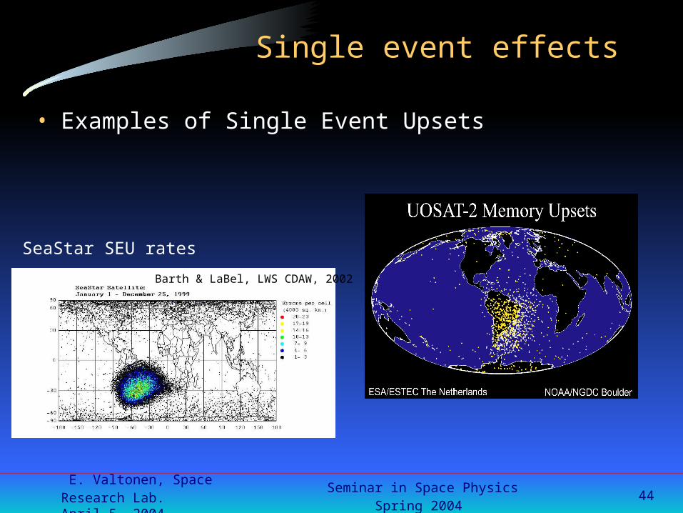
Single event effects
• Examples of Single Event Upsets
Barth & LaBel, LWS CDAW, 2002
SeaStar SEU rates

E. Valtonen, Space Research Lab.April 5, 2004
Seminar in Space PhysicsSpring 2004
45
Single Event Upsets
SOHO Solid State RecorderSEUs due to solar events
SOHO/ERNE proton fluxes at 110-140 MeV

E. Valtonen, Space Research Lab.April 5, 2004
Seminar in Space PhysicsSpring 2004
46
Sensor background and interference
• Particle-induced background Increased background due to charged particles and bremsstrahlung Increased signal processing requirements
reducing sensitivity increasing deadtime increasing signal processing complexity
Cerenkov and fluorescence radiation in optical sensors Photocathode noise in photomultiplier tubes Noise in microchannel plate detector Spurious signals Direct energy deposit in solid state detectors mimicking the expected
signal CCDs other Si detctors photomultipliers HgCdTe IR sensors etc.

E. Valtonen, Space Research Lab.April 5, 2004
Seminar in Space PhysicsSpring 2004
47
Sensor background and interference
• Effects can be due to secondary radiation Secondary electrons (delta rays) produced by ions and electrons Induced radioactivity Neutrons produced by ions Bremsstrahlung produced by electrons Electrons produced by bremsstrahlung
• Direct thermal input to low-temperature systems up to 5 Wm-2 input passive radiators designed to operate below 100 K
• Precipitation of low-energy protons and relativistic electrons from the ring current to the atmosphere subauroral red arc interfering with optical systems at low altitudes

E. Valtonen, Space Research Lab.April 5, 2004
Seminar in Space PhysicsSpring 2004
48
Sensor background and interference
Courtesy Marc SauvageCourtesy Marc SauvageCourtesy Marc Sauvage
“normal” “rev. 722”
ISO Camera Effects 97/11/06ISO Camera Effects 97/11/06
Solar proton event Nov. 97

E. Valtonen, Space Research Lab.April 5, 2004
Seminar in Space PhysicsSpring 2004
49
Sensor background and interference
ESTEC TOS/EMA
Hipparcos star-mapper count rate from Dec 1989 till Feb 1993•penetrating electrons and protons•dynamic radiation belts•fluorescence and Cherenkov flashes in optical materials•direct signals photomultiplier tubes

E. Valtonen, Space Research Lab.April 5, 2004
Seminar in Space PhysicsSpring 2004
50
Sensor background and interference
• Particles hitting CCDs charge up the pixels producing images similar to a star.
• The SOHO star tracker tracks five stars in small tracking windows. If a particle hits the tracking window it can result in a wrong assessment of the tracked star's barycenter. The SSU interprets this as a movement of the star providing wrong information to the
attitude control software.

E. Valtonen, Space Research Lab.April 5, 2004
Seminar in Space PhysicsSpring 2004
51
Sensor background and interference
SOHO/ERNE particle fluxes andSOHO/LASCO, SOHO/EIT and SOHO/CDS images April 15, 2001

E. Valtonen, Space Research Lab.April 5, 2004
Seminar in Space PhysicsSpring 2004
52
Sensor background and interference
SOHO/LASCO and SOHO/EITimages July 14, 2000
SOHO/ERNE proton intensities July 2000

E. Valtonen, Space Research Lab.April 5, 2004
Seminar in Space PhysicsSpring 2004
53
Less than 1 hour afterthe initial proton arrivalthe POLAR/VIS imageris saturated and remainsso for almost a day

E. Valtonen, Space Research Lab.April 5, 2004
Seminar in Space PhysicsSpring 2004
54
General conclusions
• Space weather does affect systems in space
• Pre-flight modelling of the environment pays back
• The response of the system to the environment must be well known and the design made accordingly to minimize the effects
• Sensitive science instruments need detailed simulations to evaluate, minimize, and remove the background
• Future systems likely to be more vulnerable More demanding performance requirements New technologies and sensor miniaturization Low power consumption Short mission development times and long mission durations