E. Todesco PROTECTION IN MAGNET DESIGN E. Todesco CERN, Geneva Switzerland With help from B....
35
E. Todesco PROTECTION IN MAGNET DESIGN E. Todesco CERN, Geneva Switzerland With help from B. Auchmann, L. Bottura, H. Felice, J. Fleiter, T. Salmi, M. Sorbi CERN, WAMSDO workshop 15 th January 2012
-
Upload
mariah-griffin -
Category
Documents
-
view
216 -
download
1
Transcript of E. Todesco PROTECTION IN MAGNET DESIGN E. Todesco CERN, Geneva Switzerland With help from B....

E. Todesco
PROTECTION IN MAGNET DESIGN
E. TodescoCERN, Geneva Switzerland
With help from B. Auchmann, L. Bottura, H. Felice, J. Fleiter, T. Salmi, M. Sorbi
CERN, WAMSDO workshop15th January 2012

E. Todesco Protection in magnet design - 2
CONTENTS
Main physics given in previous talk [talk by L. Bottura]
Hotspot temperature Maximum temperature for Nb-Ti and Nb3Sn
Time margin
Case with a dump resistor: scalingsNo dump resistor: intrinsic limits, scalings, field dependence
Budget for time margin: detection, heater delay, etcHeaters
Delays vs operational current and vs fieldHow to quench the inner layer ?
Detection
Thresholds, scalings and the case of HTSOther terms: quenchback, …
Inductive voltages

E. Todesco Protection in magnet design - 3
LIMITS TO HOTSPOT TEMPERATURE
What is the maximum acceptable hotspot temperature ?
Nb-Ti
Degradation of insulation at 500 KLimit usually set at 300 K
Nb3Sn
Weak point: avoid local stress that could damage the Nb3Sn
Limits around 300 K, with some more conservative down to 200 K and more daring up to 400 KThat’s a big difference … what to choose? Difficult to simulate, experiments should drive this choice

E. Todesco Protection in magnet design - 4
LIMITS TO HOTSPOT TEMPERATURE
Data from TQ series Degradation from 8 to 9 MIITSEstimate hot spot of 370-390 K
Data from HQHigh MIITs test, no degradation
at 18 MIITS (300 K at 12 T)
Some uncertainty due to ignorance of local field
[G. Ambrosio et al., IEEE Trans. Appl. Supercond. 18 (2008) 268]
18.3 Miits
13.2 Miits
16.9 Miits
[H. Bajas, et al., IEEE Trans. Appl. Supercond. 23 (2013) in press]
E. Todesco Protection in magnet design - 5
CONTENTS
Hotspot temperature Maximum temperature for Nb-Ti and Nb3Sn
Case with a dump resistor: scalingsTime margin
No dump resistor: intrinsic limits, scalings, field dependence
Budget for time margin: detection, heater delay, etcHeaters
Delays vs operational current and vs fieldHow to quench the inner layer ?
Detection
Thresholds, scalings and the case of HTSOther terms: quenchback, …
Inductive voltages

E. Todesco Protection in magnet design - 6
DUMPING ON RESISTOR
We neglect magnet resitance
Resistor is limited by the maximum voltage that the magnet can withstand
Protection condition: Balance between quench capital and tax
So we concludeExternal dump strategy not invariant on the magnet length
If it works for 1 m, it can be not viable for 10 m long magnets
External dump strategy: larger cables allow to gain time margin
G scales with square of cable areaG q scales with the cable area
max
0)(
)()(
0
2T
T Cu
avep
Cu dTT
TcAAdttI
od I
VR max
maxV
IL
R
L om
d
m
max
3
max
2/222 ~2
1
2)(
V
IUIL
VIdteIdttI om
omot
oq
qT )( max
Quench capital
Quench tax

E. Todesco Protection in magnet design - 7
DUMPING ON RESISTOR
Example of Q4 for the LHC upgrade [M. Segreti, J. M. Rifflet]
Two layers of 8.8 mm cable or one layer of 15.1 mm cable ?
Similar gradient 120-128 T/m and current density 700 A/mm2
One layer design has a cable cross-section 3 times larger, 13 times lower inductance – no need of heaters
G=30 MIITs, Gq=18 MIITs for one layer
G=3.2 MIITs, Gq=6.2 MIITs for one layer
qT )( max

E. Todesco Protection in magnet design - 8
NO DUMP: INTRINSIC LIMIT TO PROTECTION
No external dumpIdeal is quenching all the magnet in zero timeAn intrinsic limit to protection is the trivial balance between energy density and heat capacityNb-Ti
Typical enthalpy at 300 K is 0.65 J/mm3 → with copper is 0.7 J/mm3 → with 30% voids one has 0.5 J/mm3 (helium neglected)
Nb3Sn
Typical enthalpy at 300 K is 0.45 J/mm3 → with copper is 0.6 J/mm3 → with 30% insulation 0.5 J/mm3
HTS:
YBCO: typical enthalpy at 300 K is 0.55 J/mm3
A limit is given by the enthalpy which looks rather similar for different coils – hard limit at ~0.5 J/mm3
max
0
)(T
T
avep
avep dTTcC

E. Todesco Protection in magnet design - 9
NO DUMP: INTRINSIC LIMIT TO PROTECTION
Where are we with respect to these limits ?
Nb-Ti: 0.05 J/mm3, we are a factor 10 below (factor 3 in current )
Nb3Sn: =0.10-0.12 J/mm3,
we are a factor 4-5 below (factor 2 in current)
Energy density in the insulated cable, and limit given by enthalpy at 300 K
0.00
0.10
0.20
0.30
0.40
0.50
Ins.
cab
le e
nerg
y de
nsity
(J/
mm
3 )
TQHQ
MQXF 11 T
FrescaII
MQXC
LHC MB
HD2
HFD

E. Todesco Protection in magnet design - 10
DEFINITION OF TIME MARGIN
There are several concepts of margin for superconducting magnets
Current density marginLoadline marginTemperature margin
We propose a margin for protection: the time marginHypothesis: adiabatic approximation (conservative)
j: current density I: currentrcu: copper resistivity cp
ave: volumetric specific heat
n: fraction of copper A: cable surface
max
0)(
)()(
0
2T
T
p dTT
Tcdttj
max
0)(
)()( 2
0
2T
T Cu
avep dT
T
TcAdttI
E. Todesco Protection in magnet design - 11
DEFINITION OF TIME MARGIN
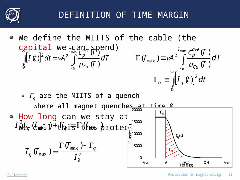
We define the MIITS of the cable (the capital we can spend)
Gq are the MIITS of a quench
where all magnet quenches at time 0
How long can we stay at nominal current I0 ? We call this the protection time margin Tq
max
0)(
)()( 2
0
2T
T Cu
avep dT
T
TcAdttI
max
0)(
)()( 2
max
T
T Cu
avep dT
T
TcAT
0
2)( dttI qq
0
5000
10000
15000
20000
-0.2 0 0.2 0.4 0.6
Cur
rent
(A
)
Time (s)
Tq
q
Iq(t)
)()( maxmax20 TTTI qq
20
maxmax
)()(
I
TTT q
q

E. Todesco Protection in magnet design - 12
NO DUMP: SCALINGS - 1
No dump strategy is independent of the length
Both R and L scale with lenght so the problem in independent of magnet length
No dump strategy is independent of the size of the cable
To be more precise: replacing a double layer coil with a single layer and double width, same U and j (see case Q4), has no impact
w w’=2w Io Io’=2Io U U’=U
Same time constant: L L’=L/4 R R’=R/44 times MIITS and Gq G G ’= 4 G Gq Gq’= 4Gq
Same time margin Tq’=Tq
What is relevant?
L
ttRI
t
tItI q
)(exp
)(exp)( 00
20
maxmax
)()(
I
TTT q
q

E. Todesco Protection in magnet design - 13
NO DUMP: SCALINGS - 2
We are going from time margin of 100 ms (LHC NbTi) to 50 ms (Nb3Sn) and even lower
Note that stored energy is not relevant: TQ worse than Fresca2Note the role of current density (up to now neglected I think, whilst the role of copper has been overestimated)
Energy density versus current density in the insulated cable
0.00
0.05
0.10
0.15
0.20
0 200 400 600 800
Ins.
cab
le e
nerg
y de
nsit
y (J
/mm
3 )
Ins. cable current density (A/mm2)
TQ(18 ms)
HQ(25 ms)
MQXF (35 ms)
11 T(35 ms)
FrescaII(200 ms)
MQXC (200-100 ms)
LHC MB (200-100 ms)
HD2(48 ms)
HFD(43 ms)

E. Todesco Protection in magnet design - 14
NO DUMP: SCALINGS - 3
So what is relevant ?One can derive an equation with intensive properties
Copper fraction cable enthalpy energy density
Average resistivity current density
where h is a parameter 1 for energy density approaching cable enthalpy
davepq UC
jT
20
20
maxmax
)()(
I
TTT q
q

E. Todesco Protection in magnet design - 15
NO DUMP: SCALINGS - 4
The role of current density is not less important than Cu fraction !
davepq UC
jT
20
0
50
100
150
200
250
0 200 400 600 800
Tim
e m
argi
n (m
s)
Ins. cable current density (A/mm2)
TQHQMQXF 11 T
FrescaII
MQXC ou
LHC MB ou
HD2 HFD
LHC MB in
MQXC in
0
50
100
150
200
250
0.8 1.0 1.2 1.4 1.6 1.8 2.0
Tim
e m
argi
n (m
s)
Cu to no-Cu ratio
TQ HQ
MQXF 11 T
FrescaII
MQXC ou
LHC MB ou
HD2HFD
LHC MB in
MQXC in
Energy density versus Cu no-Cu in the insulated cable
Time margin vs current density in the insulated cable

E. Todesco Protection in magnet design - 16
NO DUMP: dependence on field
Depending on the initial quench location one has a large variation of the budget for MIITs →large variation time margin
Example HQ: from 25 (12 T) to 45 ms (2 T)
This additional margin for low field will be needed
0
10
20
30
40
50
0 5 10 15
Tim
e m
argi
n (m
s)
Field (T)Time margin vs field in HQ (one marker per cable)

E. Todesco Protection in magnet design - 17
TIME TO QUENCH ALL THE MAGNET
Detection timeTime to get over the threshold ( a few ms → 10, 20 ms?)
Larger for lower fields !Validation time 10 ms, possibly lowered to 5 msSwitch opening 2 ms
Quench heaters Delay to quench the first cable (5-10 ms)Delay to quench the last cable (10-20 ms)
A time budget of 40 ms is at the limit
2o
qq I
T
Over
the
thre
shold
Validation time
Sw
itch
openin
g
Delay of quench heaters: first cable quenched
Delay of quench heaters: last cable quenched
The budget for the time margin

E. Todesco Protection in magnet design - 18
CONTENTS
Hotspot temperature Maximum temperature for Nb-Ti and Nb3Sn
Time margin
Case with a dump resistor: scalingsNo dump resistor: intrinsic limits, scalings, field dependence
Budget for time margin: detection, heater delay, etcHeaters
Delays vs operational current and vs fieldHow to quench the inner layer ?
Detection
Thresholds, scalings and the case of HTSOther terms: quenchback, …
Inductive voltages

E. Todesco Protection in magnet design - 19
HEATERS: FIRST OBSERVATIONS
Typical quench velocitiesAlong a cable ~10-20 m/s → 50-100 ms to make 1 mFrom turn to turn ~10 ms From outer to inner ~50 msThe build up of resistance due to quench propagation is negligibleEssential part of the modeling is the heat trasfer from the quench heaters to the coil
Interplay of heat transfer, temperature margin Heaters power is limited by voltage
The heater geometry is not indepedent of length !For long magnet one has to make heating stations to preserve a large power (~50 W/cm2 for 25 mm thick – or better say 20 W/mm3?)
Distance of stations ~100 mm to have propagation in less than 5 ms
This also makes the problem more complex

E. Todesco Protection in magnet design - 20
HEATERS: FIRST OBSERVATIONS
Simple modelEstimate the temperature margin Tcs a
Integrate specific heat from Top to Tcs to get the energy neededTime proportional to energy (one free parameter)The case 1.9 K vs 4.2 K
1.9 K: Tcs=1.9 + 4.8 = 6.7
4.2 K: Tcs=4.2 + 3.3 = 7.5
At the end «by chance» the two integrals are similar within 10-20% - so similar delays as found experimentally
More refined modelsThermal network [talk by T. Salmi]
cs
op
T
T
avepd dTTct )(
E. Todesco Protection in magnet design - 21
HEATERS DELAY
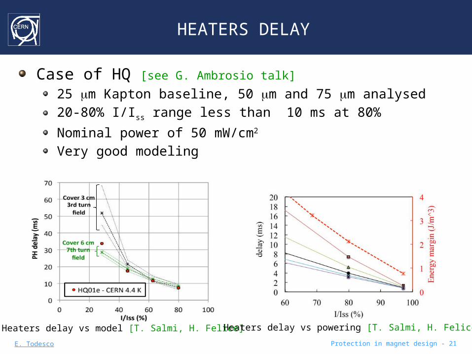
Case of HQ [see G. Ambrosio talk]
25 mm Kapton baseline, 50 mm and 75 mm analysed 20-80% I/Iss range less than 10 ms at 80%
Nominal power of 50 mW/cm2
Very good modeling
Heaters delay vs model [T. Salmi, H. Felice] Heaters delay vs powering [T. Salmi, H. Felice]

E. Todesco Protection in magnet design - 22
HEATERS DELAY
Case of 11 T125 mm Kapton baseline, 250 mm also used20-60% I/Iss range
Nominal power of 25 mW/cm2
Heaters delay for 11 T [see G. Chalchdize]

E. Todesco Protection in magnet design - 23
HEATERS DELAY
Case of MQXC (Nb-Ti coil, permeable to HeII)QH between inner and outer layer50 mm Kapton baseline10-80% I/Iss range
Nominal power of 15 mW/cm2
Heaters delay for MQXC [see G. Kirby talk]
80%

E. Todesco Protection in magnet design - 24
DELAY VS LOCAL FIELD
Problem: the heater is on part of the coil with different field → different temperature margin
Typically (LARP quads) we find a factor 2-3 between the two delaysSo if first quench is induced after 6 ms, last part of the outer quenches at 15-20 ms
Delay estimated through energy margin versus field HQ
0
1
2
3
4
5
0 2 4 6 8 10
Del
ay ti
me
(a.u
.)
B (T)
Range of field in the strands adjacent to outer layer heater
Over
the
thre
shold
Validation time
Sw
itch
openin
g
Delay of quench heaters: first cable quenched
Delay of quench heaters:
last cable quenched
E. Todesco Protection in magnet design - 25
HOW TO QUENCH THE INNER LAYER ?
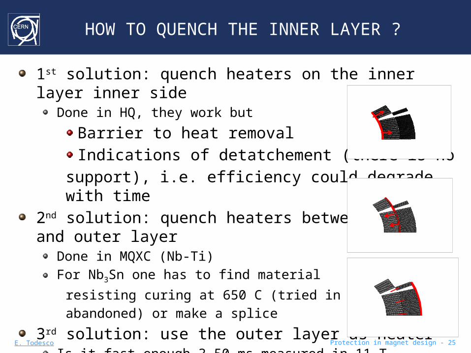
1st solution: quench heaters on the inner layer inner side
Done in HQ, they work but
Barrier to heat removalIndications of detatchement (there is no
support), i.e. efficiency could degrade with time2nd solution: quench heaters between inner and outer layer
Done in MQXC (Nb-Ti)For Nb3Sn one has to find material
resisting curing at 650 C (tried in HFD, abandoned) or make a splice
3rd solution: use the outer layer as heaterIs it fast enough ? 50 ms measured in 11 T
very relevant number for protection (to be measured and simulated)
E. Todesco Protection in magnet design - 26
CONTENTS
Hotspot temperature Maximum temperature for Nb-Ti and Nb3Sn
Time margin
Case with a dump resistor: scalingsNo dump resistor: intrinsic limits, scalings, field dependence
Budget for time margin: detection, heater delay, etcHeaters
Delays vs operational current and vs fieldHow to quench the inner layer ?
Detection
Thresholds, scalings and the case of HTSOther terms: quenchback, …
Inductive voltages

E. Todesco Protection in magnet design - 27
DETECTION
Time to go above the threshold
Up to 40 K low dependence of resistivity on temperature
Estimate for HQ, at 12 TVth=100 mV jo,Cu=1400 A/mm2
vNPZ= 20 m/s r(12 )T =6 ×10⁻¹⁰ W m
td=6 ms (reasonable)
oCu
NPZoth I
A
tvItRV
)( CuoNPZ
thd
jv
Vt
,
1

E. Todesco Protection in magnet design - 28
DETECTION
Time to go above the threshold
Strong influence of field
(12 ) / (0 ) rk T rk T ~2 or 1Tcs-Top~5 K at 12 T, Tcs-Top~15 K at 0 T
vNPZ(12 T)/ v NPZ(0 T) ~ 2.5 or 1.7
vNPZ r(12 T)/ v NPZ r(0 T) ~ 10 or 6
So at 0 T NPZ can propagate 10 times slower …Detection time can be much longer for low fieldLarger budget (20 ms) partially compensates
Careful study of quench velocity needed [See H. ten Kate talk]
For HTS the vNPZ is a factor 100 less so the detection is the real bottleneck [See J. Schwartz talk]
oCu
NPZoth I
A
tvItRV
)(
opcsNPZ TT
v
CuoNPZ
th
jv
Vt
,
1

E. Todesco Protection in magnet design - 29
QUENCHBACK
For LARP quads we have evidence of strong quenchback
Method: open switch and dump current on resistor – estimate resistance from dI/dt
This effect can be dominant! We can get wrong conclusionsThe initial ramp rate is huge! with I=15 kA, t=1, dI/dt= 15000 A/s …
High MIITs test [H. Bajas, M. Bajko, H. Felice, G. L. Sabbi, T. Salmi, ASC 2012]
E. Todesco Protection in magnet design - 30
CONTENTS
Hotspot temperature Maximum temperature for Nb-Ti and Nb3Sn
Time margin
Case with a dump resistor: scalingsNo dump resistor: intrinsic limits, scalings, field dependence
Budget for time margin: detection, heater delay, etcHeaters
Delays vs operational current and vs fieldHow to quench the inner layer ?
Detection
Thresholds, scalings and the case of HTSOther terms: quenchback, …
Inductive voltages

E. Todesco Protection in magnet design - 31
INDUCTIVE VOLTAGES
During the quench one has a resistive voltage propto I (where the magnet is quenched) an inductive voltage propto dI/dt (everywhere)
The two compensate at the end of the magnet in case of no dump resistorWorst estimate:
Outer layer quenched – inner layer notEqual split of inductance
So the highest voltage vs time is
where the I(t) is computed for a fully quenched outer layer
dt
dILV inin IR
dt
dILV ououou
2~~
LLL ouin
dt
tdIL
ntV in
p
)(1)(max

E. Todesco Protection in magnet design - 32
INDUCTIVE VOLTAGES - scaling
The inductive voltage is proportional to magnet length
Current inpendendent of length, derivative as wellInductance propto length
The inductive voltage is reduced for larger cables
Usual case two magnets same field and energy, one with two layers and width w, one with one layer and width 2wI→ I’=2I w→ w’=2w L→ L’=L/4 R→ R’=R/4t→ t’= t Vmax→ Vmax’=Vmax /2
So small cables can be dangerous for long magnet
dt
tdIL
ntV in
p
)(1)(max
E. Todesco Protection in magnet design - 33
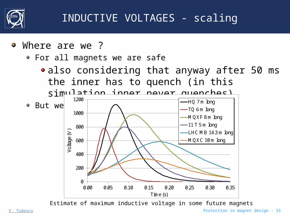
INDUCTIVE VOLTAGES - scaling
Where are we ?For all magnets we are safe
also considering that anyway after 50 ms the inner has to quench (in this simulation inner never quenches)
But we are not so far from the limit
0
200
400
600
800
1000
1200
0.00 0.05 0.10 0.15 0.20 0.25 0.30 0.35
Vol
tage
(V
)
Time (s)
HQ 7 m long
TQ 6 m long
MQXF 8 m long
11 T 5 m long
LHC MB 14.3 m long
MQXC 10 m long
Estimate of maximum inductive voltage in some future magnets

E. Todesco Protection in magnet design - 34
CONCLUSIONS
With Nb3Sn magnets we are entering a new regime of protection
We are a factor 5 below energy density limit set by heat capacity
It was a factor 10 with Nb-TiThe time margin needed to quench the magnet is of ~50 ms
It is a factor 2-4 larger for LHC MB and MQXCLarge current densities are challenging …
TQ was probably impossible to protect in long version
How heaters work is a key pointDelays of 5-10 ms are acceptableOptimize power, thickness of insulation, coverageThe question of the inner layer: what to do?
Measuring and modeling the delay between outer and inner quench

E. Todesco Protection in magnet design - 35
CONCLUSIONS
Detection timeIs the main bottlenck for HTSIt can become critical for Nb3Sn at low fields
Quenchback can become the dominant mechanism for LARP Nb3Sn magnets without cored cable
Measurements needed, with low dump resistor
Inductive voltages are not a problem for the magnets being planned
They scale with magnet lengthThe inner triplet for the HL-LHC is just going close to this limit