BIQ Workshop, September 15 Collaboration of many teams: BLM, Collimation, FLUKA, LIBD, OP, RF, etc....
24
-
Upload
byron-miller -
Category
Documents
-
view
214 -
download
0
Transcript of BIQ Workshop, September 15 Collaboration of many teams: BLM, Collimation, FLUKA, LIBD, OP, RF, etc....

Quench Test Analysis Results
BIQ Workshop, September 15
Collaboration of many teams: BLM, Collimation, FLUKA, LIBD, OP, RF, etc.
B. Auchmann, T. Baer, M. Bednarek, G. Bellodi, C. Bracco, R. Bruce, F. Cerutti, V. Chetvertkova, B. Dehning, P. P. Granieri, W. Hofle, E. B. Holzer, A. Lechner, E. Nebot Del Busto,
A. Priebe, S. Redaelli, B. Salvachua, M. Sapinski, R. Schmidt, N. Shetty, E. Skordis, M. Solfaroli, D. Valuch, A. Verweij, J. Wenninger, D. Wollmann, M. Zerlauth, and more…
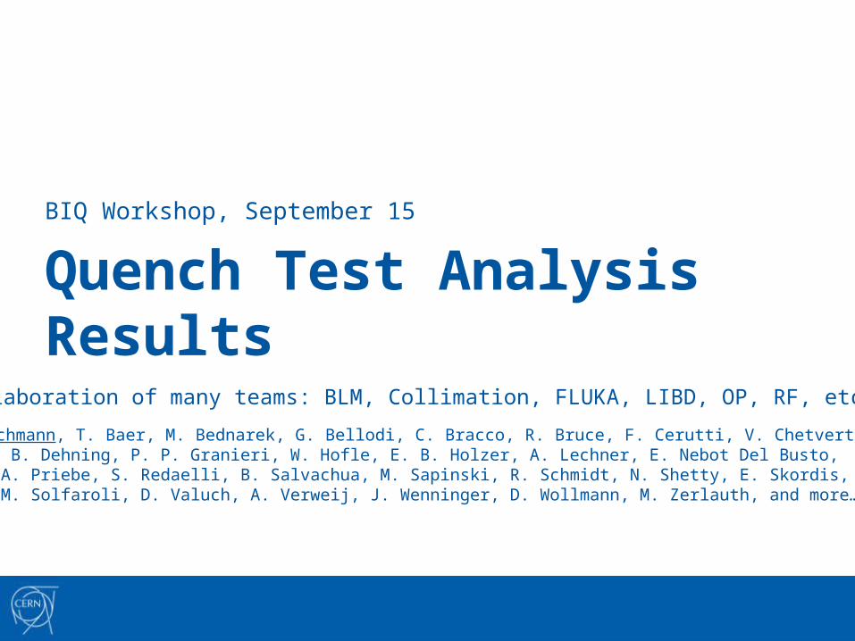
Overview• Summary of quench-test results per time regime.
• What are the implications for BLM settings?
Regime Method Energy Temperature
short kick 450 GeV 1.9 K
short collimation 0.45/6 TeV 4.5 K
intermediate wire scanner 3.5 TeV 4.5 K
intermediate orbit bump 4 TeV 1.9 K
steady-state collimation 4 TeV 1.9 K
steady-state dyn. orbit bump 3.5 TeV 1.9 K
steady-state orbit bump 4 TeV 1.9 K
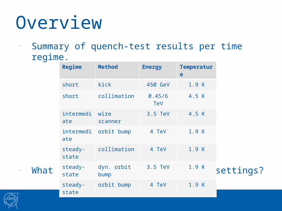
Quench Test Analysis What is the energy deposition in the coil at the moment of quench?
ParticleShower
FCBM: loss rate
QPS: moment of quench
Particle tracking: spatial distribution
BLM signals
Val
idat
ion
Inpu
tA
naly
sis
Electro-ThermalEstimate (MQED)
BLM: normalizedtime distribution
P. shower: norm.space distribution
Quench test
QPS: moment of quench
Subscale experiments
Quench Level
Upper boundor estimate
Lower bound
ParticleTracking
Settings: bump amplitude etc.
Beam parametermeasurements: ε, Q, etc.
BLM normalizedtime distribution
BPM signals
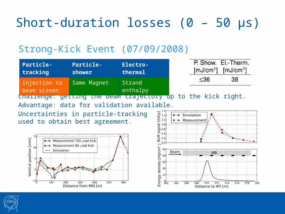
Short-duration losses (0 – 50 µs)
Strong-Kick Event (07/09/2008)
Challenge: getting the beam trajectory up to the kick right.
Advantage: data for validation available.
Uncertainties in particle-tracking inputused to obtain best agreement.
Particle-tracking Particle-shower Electro-thermal
Injection to beam screen
Same Magnet Strand enthalpy
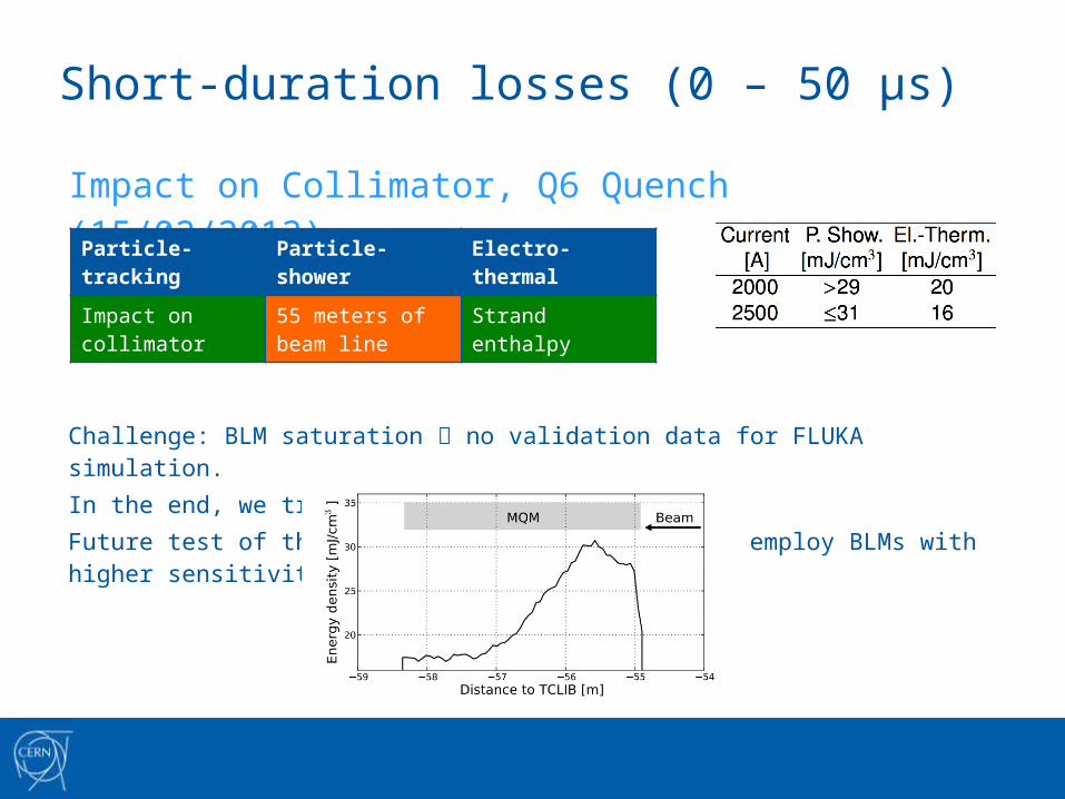
Short-duration losses (0 – 50 µs)
Impact on Collimator, Q6 Quench (15/02/2013)
Challenge: BLM saturation no validation data for FLUKA simulation.In the end, we trust the electro-thermal model.Future test of this kind (Q4, LIBD team) should employ BLMs with higher sensitivity and dynamic range.
Particle-tracking Particle-shower Electro-thermal
Impact on collimator
55 meters of beam line
Strand enthalpy
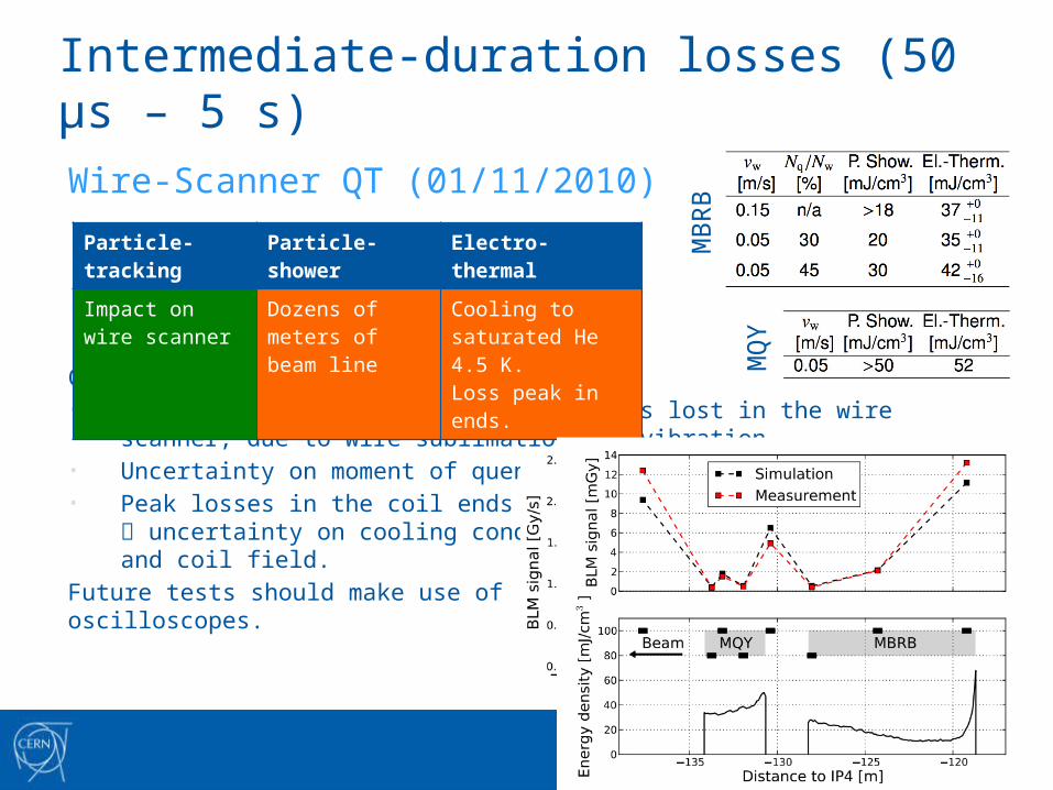
Intermediate-duration losses (50 µs – 5 s)
Wire-Scanner QT (01/11/2010)
Challenges: • Determination of the number of protons lost in the wire scanner, due to wire
sublimation and vibration.• Uncertainty on moment of quench.• Peak losses in the coil ends
uncertainty on cooling conditions and coil field.
Future tests should make use of oscilloscopes.
Particle-tracking Particle-shower Electro-thermal
Impact on wire scanner
Dozens of meters of beam line
Cooling to saturated He 4.5 K.Loss peak in ends.
MB
RB
MQ
Y
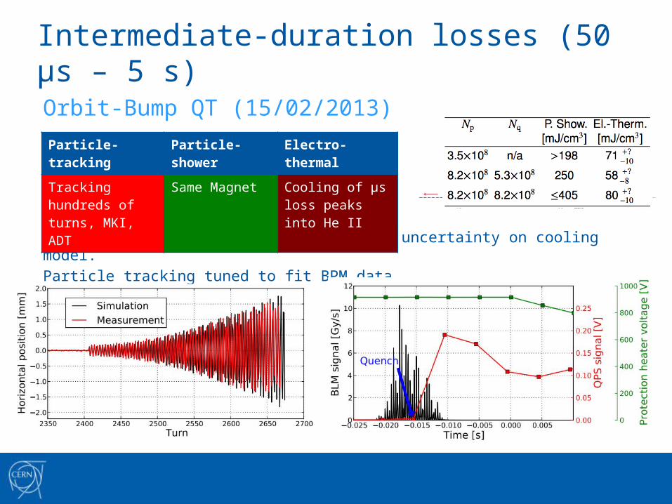
Intermediate-duration losses (50 µs – 5 s)
Orbit-Bump QT (15/02/2013)
Uncertainty on moment of quench.
Loss spikes of several µs even larger uncertainty on cooling model.
Particle tracking tuned to fit BPM data.
Particle-tracking Particle-shower Electro-thermal
Tracking hundreds of turns, MKI, ADT
Same Magnet Cooling of µs loss peaks into He II
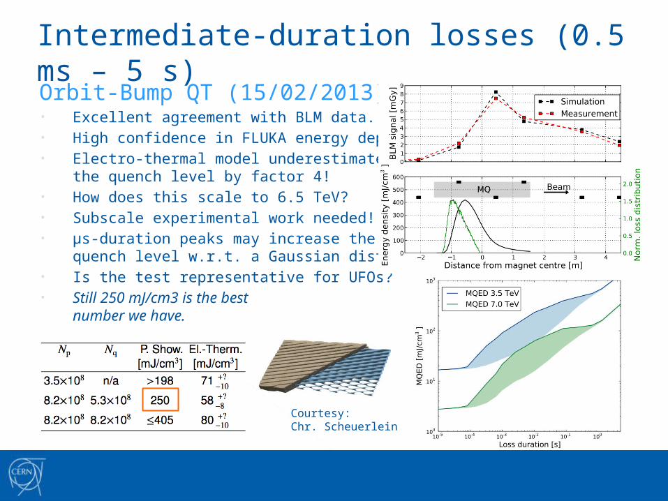
Intermediate-duration losses (0.5 ms – 5 s)Orbit-Bump QT (15/02/2013)• Excellent agreement with BLM data.• High confidence in FLUKA energy deposition.• Electro-thermal model underestimates
the quench level by factor 4!• How does this scale to 6.5 TeV?• Subscale experimental work needed!• µs-duration peaks may increase the
quench level w.r.t. a Gaussian distribution.• Is the test representative for UFOs?• Still 250 mJ/cm3 is the best
number we have.
Courtesy:Chr. Scheuerlein
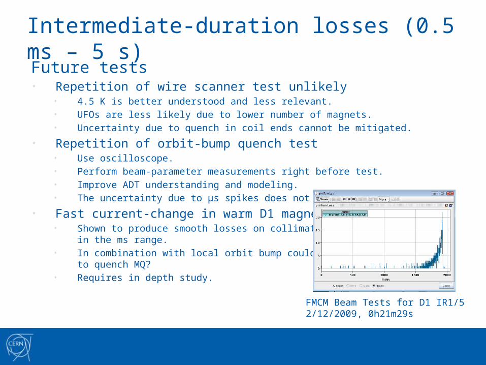
Intermediate-duration losses (0.5 ms – 5 s)Future tests• Repetition of wire scanner test unlikely
• 4.5 K is better understood and less relevant.• UFOs are less likely due to lower number of magnets.• Uncertainty due to quench in coil ends cannot be mitigated.
• Repetition of orbit-bump quench test• Use oscilloscope.• Perform beam-parameter measurements right before test.• Improve ADT understanding and modeling.• The uncertainty due to µs spikes does not go away.
• Fast current-change in warm D1 magnet• Shown to produce smooth losses on collimator
in the ms range.• In combination with local orbit bump could be used
to quench MQ?• Requires in depth study.
FMCM Beam Tests for D1 IR1/52/12/2009, 0h21m29s
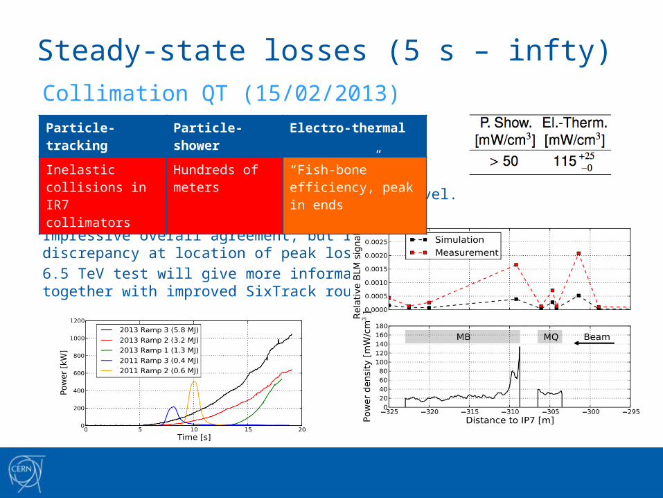
Steady-state losses (5 s – infty)Collimation QT (15/02/2013)
No quench, hence no validation of quench level.
Peak losses in MB coilends.
Impressive overall agreement, but important discrepancy at location of peak losses.
6.5 TeV test will give more information,together with improved SixTrack routines.
Particle-tracking Particle-shower Electro-thermal
Inelastic collisions in IR7 collimators
Hundreds of meters
“Fish-bone” efficiency, peak in ends
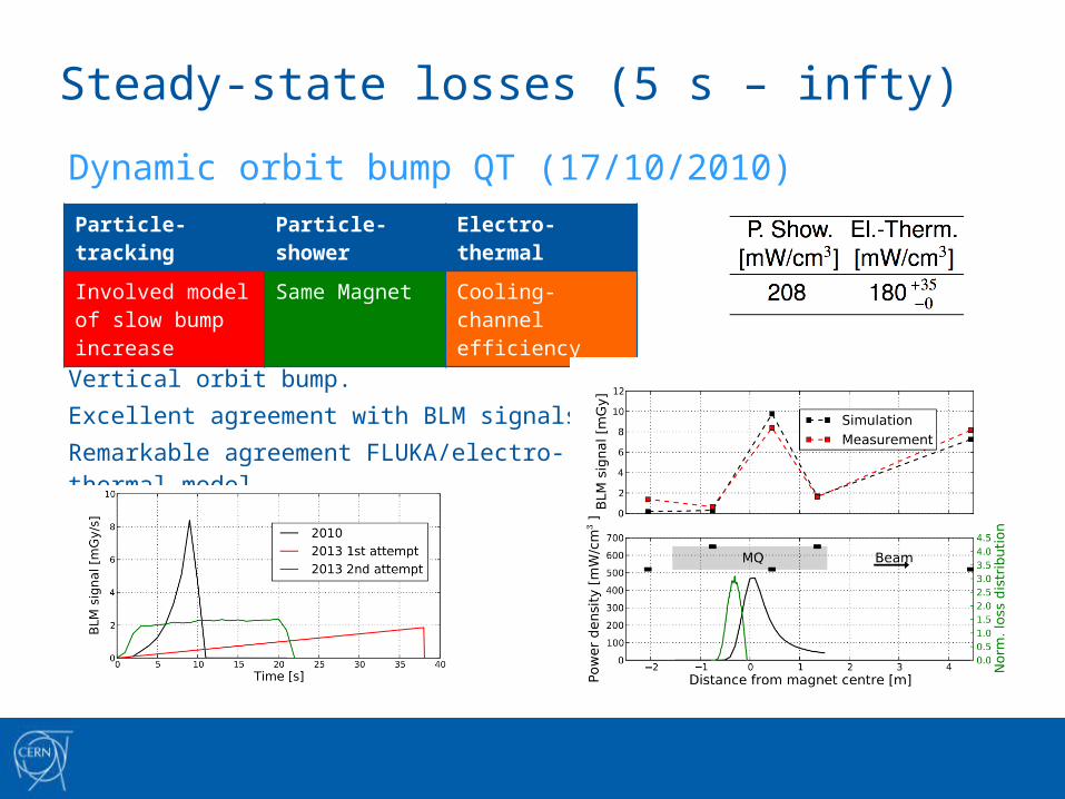
Steady-state losses (5 s – infty)Dynamic orbit bump QT (17/10/2010)
Vertical orbit bump.Excellent agreement with BLM signals.Remarkable agreement FLUKA/electro-thermal model.
Particle-tracking Particle-shower Electro-thermal
Involved model of slow bump increase
Same Magnet Cooling-channel efficiency
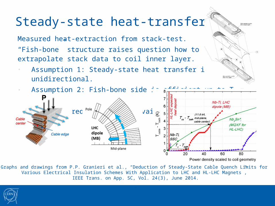
Steady-state heat-transfer modelMeasured heat-extraction from stack-test.“Fish-bone” structure raises question how to extrapolate stack data to coil inner layer.• Assumption 1: Steady-state heat transfer is unidirectional.• Assumption 2: Fish-bone side is efficient up to Ts = Tλ.
No entirely predictive model available.
Graphs and drawings from P.P. Granieri et al., “Deduction of Steady-State Cable Quench Limits for Various Electrical Insulation Schemes With Application to LHC and HL-LHC Magnets”,
IEEE Trans. on App. SC, Vol. 24(3), June 2014.
“
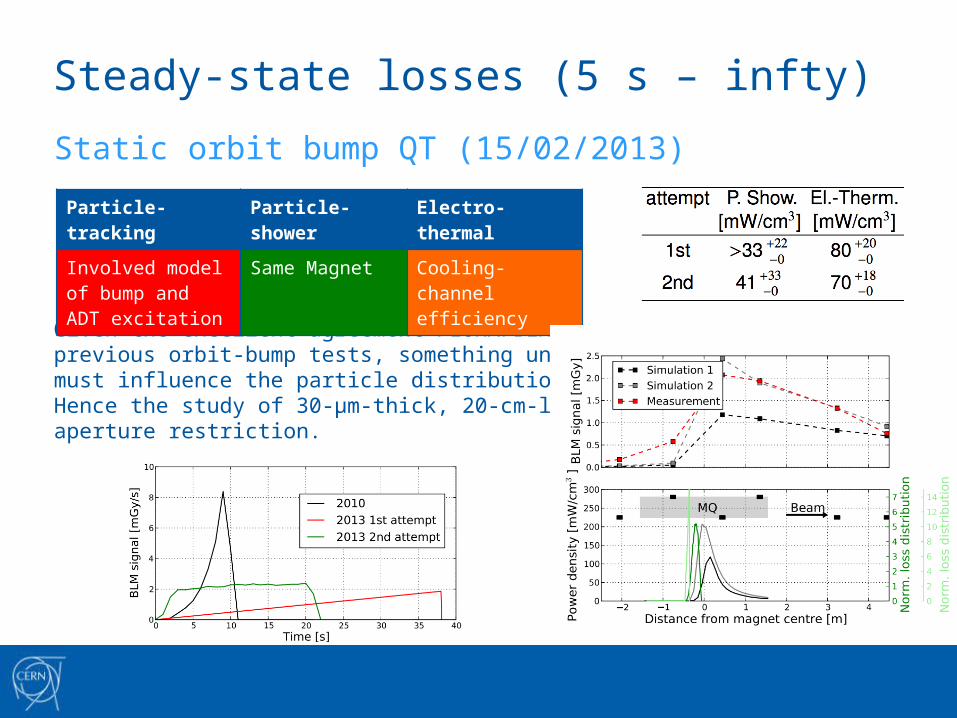
Steady-state losses (5 s – infty)Static orbit bump QT (15/02/2013)
Given the excellent agreement FLUKA/BLM inprevious orbit-bump tests, something unknownmust influence the particle distribution.Hence the study of 30-µm-thick, 20-cm-long aperture restriction.
Particle-tracking Particle-shower Electro-thermal
Involved model of bump and ADT excitation
Same Magnet Cooling-channel efficiency
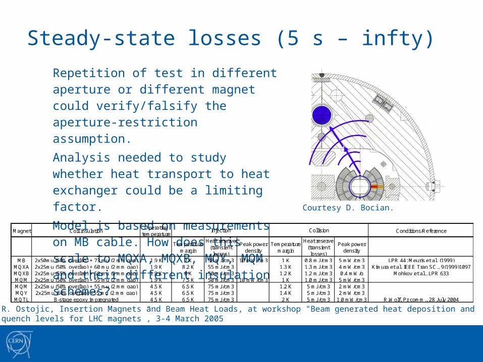
Steady-state losses (5 s – infty)Repetition of test in different aperture or different magnet could verify/falsify the aperture-restriction assumption.Analysis needed to study whether heat transport to heat exchanger could be a limiting factor.Model is based on measurements on MB cable. How does this scale to MQXA, MQXB, MQY, MQM and their different insulation schemes?
Magnet Coil insulationOperating
temperatureConditions/Reference
Temperature margin
Heat reserve (transient losses)
Peak power density
Temperature margin
Heat reserve (transient losses)
Peak power density
MB 2x50mu (50% overlap) + 73 mu (2 mm gap) 1.9 K 7 K 38 mJ/cm3 10 mW/cm3 1 K 0.8 mJ/cm3 5 mW/cm3 LPR 44; Meuris et al. (1999)MQXA 2x25mu (50% overlap) + 60 mu (2 mm gap) 1.9 K 8.2 K 55 mJ/cm3 1.3 K 1.3 mJ/cm3 4 mW/cm3 Kimura et al, IEEE Tran SC., 9(1999)1097MQXB 2x25mu (55% overlap) + 50 mu (2 mm gap) 1.9 K 8 K 50 mJ/cm3 1.2 K 1.2 mJ/cm3 0.4 mW/g Mohkov et al., LPR 633MQM 2x25mu (50% overlap) + 55 mu (2 mm gap) 1.9 K 7.5 K 50 mJ/cm3 10 mW/cm3 1 K 1.0 mJ/cm3 5 mW/cm3MQM 2x25mu (50% overlap) + 55 mu (2 mm gap) 4.5 K 6.5 K 75 mJ/cm3 1.2 K 5 mJ/cm3 2 mW/cm3MQY 2x25mu (50% overlap) +55 mu (2 mm gap) 4.5 K 6.5 K 75 mJ/cm3 1.4 K 5 mJ/cm3 2 mW/cm3MQTL B-stage epoxy impregnated 4.5 K 6.5 K 75 mJ/cm3 2 K 5 mJ/cm3 1.0 mW/cm3 R.Wolf, Pr comm., 28 July 2004
Injection Collision
R. Ostojic, Insertion Magnets and Beam Heat Loads, at workshop "Beam generated heat deposition and quench levels for LHC magnets”, 3-4 March 2005
Courtesy D. Bocian.
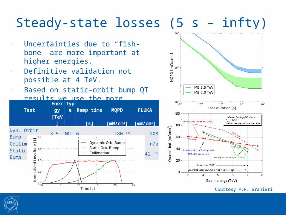
Steady-state losses (5 s – infty)
• Uncertainties due to “fish-bone” are more important at higher energies.
• Definitive validation not possible at 4 TeV.• Based on static-orbit bump QT results we
use the more conservative assumption.• More input in tomorrow’s morning session!
Test Energy Type Ramp time MQPD FLUKA[TeV] [s] [mW/cm3] [mW/cm3]
Dyn. Orbit Bump 3.5 MQ 6 180 +35 208Collimation 4 MB 15 115 +25 n/aStatic Orbit Bump 4 MQ infty 70 +18 41 +33
Courtesy P.P. Granieri
Steady-state losses (5 s – infty)
• Future tests• Repetition of orbit-bump test in
• Different MQ• Also in MQM, MQY – even triplet magnets?
• Collimation quench test• Will give improved analysis and, perhaps, a quench?
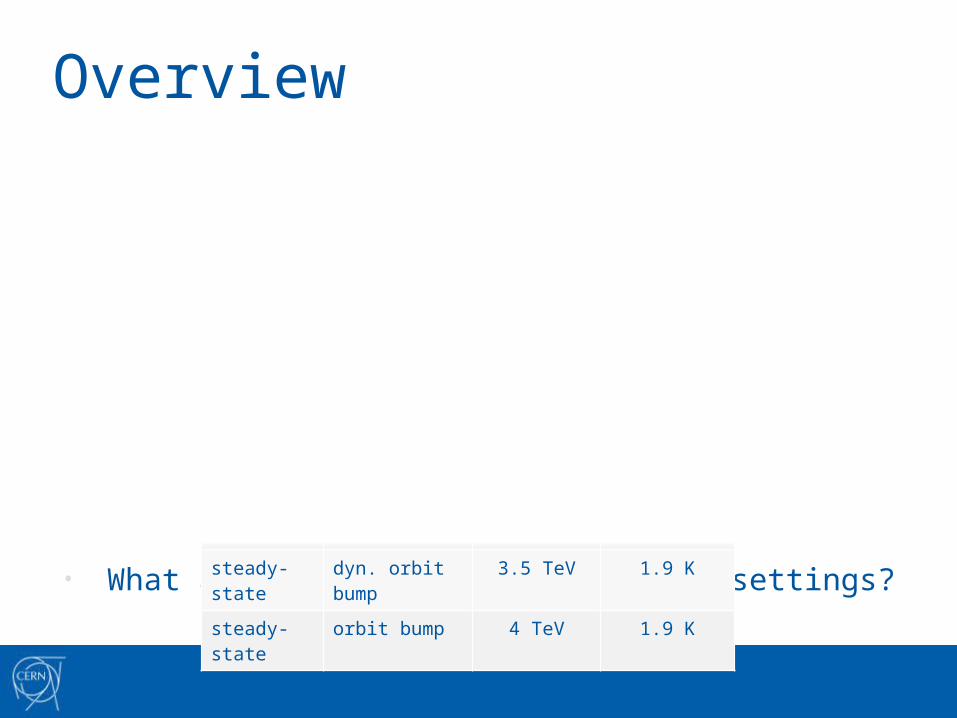
Overview• Summary of quench-test results per time regime.
• What are the implications for BLM settings?
Regime Method Energy Temperature
short kick 450 GeV 1.9 K
short collimation 0.45/6 TeV 4.5 K
intermediate wire scanner 3.5 TeV 4.5 K
intermediate orbit bump 4 TeV 1.9 K
steady-state collimation 4 TeV 1.9 K
steady-state dyn. orbit bump 3.5 TeV 1.9 K
steady-state orbit bump 4 TeV 1.9 K
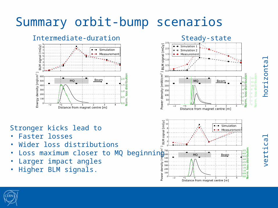
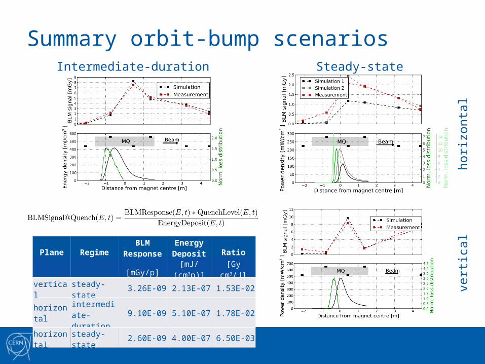
Summary orbit-bump scenarios
horiz
onta
lve
rtic
al
Intermediate-duration Steady-state
Stronger kicks lead to• Faster losses• Wider loss distributions• Loss maximum closer to MQ beginning• Larger impact angles• Higher BLM signals.
Summary orbit-bump scenarios
horiz
onta
lve
rtic
al
Intermediate-duration Steady-state
Plane RegimeBLM
ResponseEnergy Deposit Ratio
[mGy/p] [mJ/(cm3p)] [Gy cm3/J]vertical steady-state 3.26E-09 2.13E-07 1.53E-02
horizontalintermediate-duration
9.10E-09 5.10E-07 1.78E-02
horizontal steady-state 2.60E-09 4.00E-07 6.50E-03
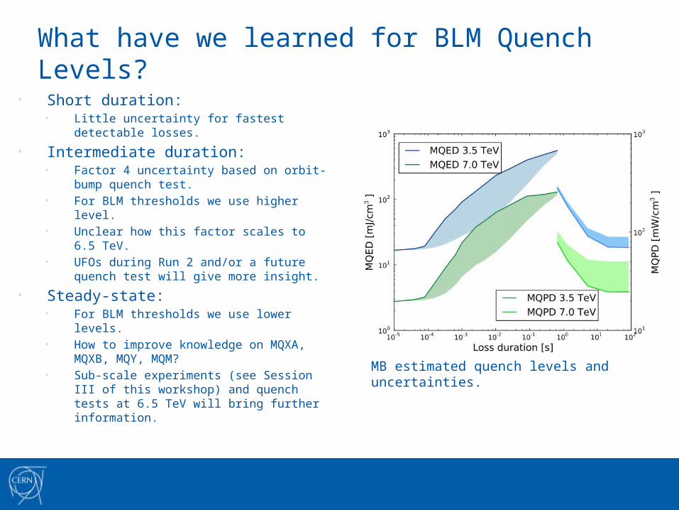
What have we learned for BLM Quench Levels?
• Short duration:• Little uncertainty for fastest detectable
losses.
• Intermediate duration:• Factor 4 uncertainty based on orbit-bump
quench test.• For BLM thresholds we use higher level.• Unclear how this factor scales to 6.5 TeV.• UFOs during Run 2 and/or a future
quench test will give more insight.
• Steady-state:• For BLM thresholds we use lower levels.• How to improve knowledge on MQXA,
MQXB, MQY, MQM?• Sub-scale experiments (see Session III of
this workshop) and quench tests at 6.5 TeV will bring further information.
MB estimated quench levels and uncertainties.
Conclusion
• The organization of quench tests and the analysis of beam-loss events are highly collaborative and multi-disciplinary efforts!
• In principle we should aim to understand beam-induced quenches in all aspects to within 20% - though it may still take some time to get there.
• On the long run we must aim to understand every beam-loss scenario for BLM thresholds to within this precision.• This will allow for better informed decisions whenever either a beam-
induced quench or too many spurious triggers occur.• See tomorrow’s afternoon session for more on BLM thresholds!
• Sub-scale experimental work has to complement quench tests to pin down the quench levels in a single predictive model. • See tomorrow’s morning session on both, experimental and modeling
work!