e-Gladiator Admittance Switch Manual v1.15 admittance switch manual v1.15.pdf · An All-round Point...
39
Sultan Sonar Manual Rev 1.0 A Higher Level of Performance www.hawkmeasure.com For more information, please visit > Gladiator Admittance Smart Switch Series An All-round Point Level Switch Manual
Transcript of e-Gladiator Admittance Switch Manual v1.15 admittance switch manual v1.15.pdf · An All-round Point...
Sultan Sonar Manual Rev 1.0
A Higher Level of Performance
www.hawkmeasure.comFor more information, please visit >
GladiatorAdmittance Smart Switch SeriesAn All-round Point Level Switch
Manual
Table of Contents
2
Contents
Gladiator Admittance Smart Switch Series
PROPRIETARY NOTICEThe information contained in this publication is derived in part from proprietary and patent data. This information has been prepared for the express purpose of assisting operating and maintenance personnel in the efficient use of the instrument described herein. Publication of this information does not convey any rights to use or reproduce it, or to use for any purpose other than in connection with the installation, operation and maintenance of the equipment described herein.
WARNINGThis instrument contains electronic components that are susceptible to damage by static electricity. Proper handling procedures must be observed during the removal, installation, or handling of internal circuit boards or devices:
Handling Procedure:1. Power to unit must be removed prior to commencement of any work.
2. Personnel must be grounded, via wrist strap or other safe, suitable means, before any printed circuit board or other internal devices are installed, removed or adjusted.3. Printed circuit boards must be transported in a conductive bag or other conductive container. Boards must not be removed from protective container until the immediate time of installation. Removed boards must be placed immediately in a protective container for transport, storage, or return to factory.
Comments:This instrument is not unique in its content of ESD (electrostatic discharge) sensitive components. Most modern electronic designs contain components that utilize metal oxide technology (NMOS, CMOS, etc.). Experience has proven that even small amounts of static electricity can damage or destroy these devices. Damaged components, even though they appear to function properly, exhibit early failure
Overview 3
Principle of Operation 3Typical Uses 3Primary Areas of Application 3Features 3Function 3
Typical Applications 4
Cyclone Bin Level Switch 4Presence / Absence of Liquid In Pipe Detection 4High and Low-level Switch In A Hopper 5
Dimensions 6
Remote Amplifier 6Remote Probe 7Integral Probe 7Flexible Cable Probe 8High Temperature Probe (<250°C, <482°F) 9High Temperature Extensions (<250°C, 482°F) 9High Temperature Probe (450°C, 842°F) 9 Pump Protection Version 10 Flush Mount Version 10
Mounting 11
Mounting Examples 12
Mounting 12
Flexible Cable Probe Adjustment 13
Notes For Adjusting Probe Rope Length 13
Wiring 14
Integral Probe 14Remote Probe to Amplifier 15Relay Functions 16
Multidrop Connections 17Test Terminal Function Selection (SPDT Only) 18
Setup Procedure 19
Integral Probe Functionality Layout 19Integral Probe Version 20Integral Probe Version 22Remote Functionality Layout 22Remote Version 23
Main Menu & Interface 24
Remote Main Menus & Interface - Remote System 24
Software Parameters 25
Operational Diagnostics (Remote Type Only) 25Quickset Menu - Parameters 26Advanced Menu - Parameters 27
Software Flow Chart 28
Troubleshooting 32
Remote Version 32
Part Numbering 33
Integral Probe Version 33Remote Version 34 Mounitng Flanges 34Pump Protection Version 36 Flush Mount Version 36
Probe Configuration / Approvals Table 37
Specifications 38
Dielectric Constants Table 39
Overview
Principle of Operation
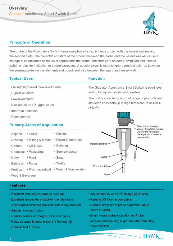
The probe of the Admittance Switch forms one plate of a capacitance circuit, with the vessel wall making the second plate. The dielectric constant of the product between the probe and the vessel wall will cause a change of capacitance as the level approaches the probe. The change is detected, amplified and used to switch a relay for indication or control purposes. A special circuit is used to ignore product build-up between the sensing probe (active element) and guard, and also between the guard and vessel wall.
• Excellent immunity to product build-up
• Excellent temperature stability - no false trips
• Non contact switching possible with many products
• Simple ‘1-minute’ setup
• Remote sensor or Integral ‘all in one’ types
• Relay outputs: Integral probe (1) Remote (2)
• Remote test function
• Adjustable ON and OFF delays (0-20 sec)
• Remote 3G Connection option
• Remote amplifier to probe separation up to 500m (1640ft)
• Bright visual status indication on Probe
• Independent housing alignment after mounting thread locked.
Typical Uses
• Failsafe high-level / low-level alarm
• High-level alarm
• Low-level alarm
• Blocked chute / Plugged chute
• Interface detection
• Pump control.
Features
3
Gladiator Admittance Smart Switch Series
Function
The Gladiator Admittance Smart Switch is point level switch for liquids, solids and powders.
The unit is suitable for a broad range of products and dielectric constants up to high temperature of 450oC (842oF).
Primary Areas of Application
• Asphalt
• Brewing
• Cement
• Chemical
• Dairy
• Edible oil
• Fertilizer
• Food & Beverage
• Glass
• Mining & Metals
• Oil & Gas
• Packaging
• Paint
• Paper
• Pharmaceutical
• Plastics
• Power Generation
• Refining
• Semiconductor
• Sugar
• Textile
• Water & Wastewater. Probe
Probe Insulation
Guard
Material build up
> 10
0mm
Ground the housing to vessel, if vessel is metallic.Ground the housing to plant ground, if vessel is non-metallic.
Flatten roof

Typical Applications
4
Gladiator Admittance Smart Switch Series
High level switch in grain application
Cyclone Bin Level Switch
Presence / Absence of Liquid In Pipe Detection
Sealing plug available allowing removal of unit without pipe leakage
Low level
High level switch in plastic pellet silo

5
Typical ApplicationsGladiator Admittance Smart Switch Series
Continuous filling with build-up on probe
High and Low-level Switch In A Hopper
Low level (top mounted)High level (top mounted)
Low level(side mounted)
If impact from falling material is expected, mount a protection plate above the probe to ensure no physical damage can occur to the probe in normal operation. If it is not possible to do this or to move the probe to an alternative position, use a microwave switch.
See www.hawkmeasure.com for further information on Microwave switches and other level products.
6
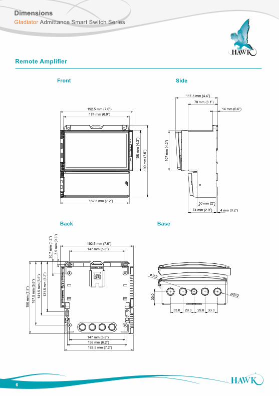
DimensionsGladiator Admittance Smart Switch Series
Remote Amplifier
14 mm (0.6”)
74 mm (2.9”)
78 mm (3.1”)
107
mm
(4.2
”)
111.5 mm (4.4”)
4 mm (0.2”)
50 mm (2”)
131.
5 m
m (5
.2”)
7.5
mm
(0.3
”)
192.5 mm (7.6”)
141.
5 m
m (5
.6”)
190
mm
(7.5
”)
182.5 mm (7.2”)
147 mm (5.8”)
167.
5 m
m (6
.6”)
147 mm (5.8”)
30.7
mm
(1.2
”)
158 mm (6.2”)
108
mm
(4.3
”)
190
mm
(7.5
”)
174 mm (6.9”)192.5 mm (7.6”)
182.5 mm (7.2”)
30.0 20.2
33.029.029.033.0
16.2
Front Side
Back Base
7
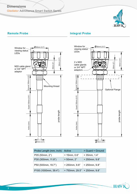
DimensionsGladiator Admittance Smart Switch Series
Remote Probe Integral Probe
Window forviewing statusLEDs
2 x M20 cable glandsor 3/4” NPT adaptors
Optional Flange
85mm (3.3”)
16mm (0.6”)
Gro
und
100m
m (3
.9”)
Gua
rd 1
50m
m (5
.9”)
Act
ive
(mm
) prob
e le
ngth
50m
m (2
”)
Window forviewing statusLEDs
M20 cable glandor 3/4” NPT adaptor
Mounting thread
85mm (3.3”)
16mm (0.6”)
Gro
und
100m
m (3
.9”)
Gua
rd 1
50m
m (5
.9”)
Act
ive
(mm
) prob
e le
ngth
50m
m (2
”)
90m
m (3
.5”)
90m
m (3
.5”)
Probe Length (mm, inch) Active + Guard + Ground
P05 (50mm, 2”) = 15mm, 0.6” + 35mm, 1.4”
P30 (300mm, 11.8”) = 50mm, 2” + 250mm, 9.8”
P50 (500mm, 19.7”) = 250mm, 9.8” + 250mm, 9.8”
P100 (1000mm, 39.4”) = 750mm, 29.5” + 250mm, 9.8”
8
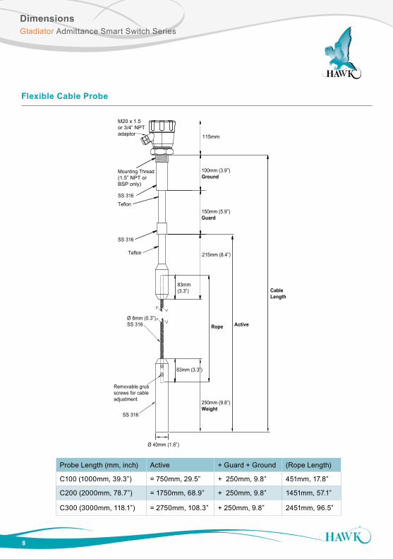
DimensionsGladiator Admittance Smart Switch Series
115mm
Cable Length (mm, inch) Active + Guard + Ground (Rope Length)
C100 (1000mm, 39.3”) = 750mm, 29.5” + 250mm, 9.8” 451mm, 17.8”C200 (2000mm, 78.7”) = 1750mm, 68.9” + 250mm, 9.8” 1451mm, 57.1”C300 (3000mm, 118.1”) = 2750mm, 108.3” + 250mm, 9.8” 2451mm, 96.5”
100mm (3.9”)Ground
150mm (5.9”)Guard
Rope
250mm (9.8”)Weight
Active
Cable Length
83mm(3.3”)
83mm (3.3”)
215mm (8.4”)
M20 x 1.5or 3/4” NPT adaptor
Mounting Thread(1.5” NPT or BSP only)
SS 316Teflon
SS 316
Teflon
Ø 8mm (0.3”) SS 316
Removable grub screws for cable adjustment
SS 316
Ø 40mm (1.6”)
Probe Length (mm, inch) Active + Guard + Ground (Rope Length)
C100 (1000mm, 39.3”) = 750mm, 29.5” + 250mm, 9.8” 451mm, 17.8”
C200 (2000mm, 78.7”) = 1750mm, 68.9” + 250mm, 9.8” 1451mm, 57.1”
C300 (3000mm, 118.1”) = 2750mm, 108.3” + 250mm, 9.8” 2451mm, 96.5”
Flexible Cable Probe
9
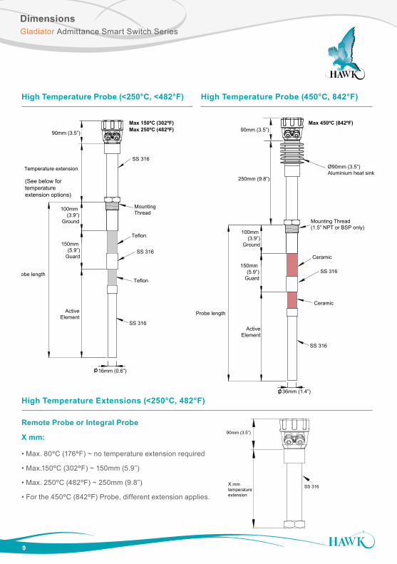
DimensionsGladiator Admittance Smart Switch Series
Probe length
150mm (5.9”)
Guard
ActiveElement
Temperature extension
100mm (3.9”)
Ground
Teflon
Teflon
Max 150ºC (302ºF)Max 250ºC (482ºF)
SS 316
SS 316
SS 316
16mm (0.6”)
Mounting Thread
Ø90mm (3.5”) Aluminium heat sink
Ceramic
Ceramic
Max 450ºC (842ºF)
SS 316
SS 316
36mm (1.4”)
250mm (9.8”)
Probe length
150mm (5.9”)
Guard
ActiveElement
100mm (3.9”)
Ground
Mounting Thread (1.5” NPT or BSP only)
90mm (3.5”)90mm (3.5”)
(See below for temperature extension options)
High Temperature Probe (<250°C, <482°F) High Temperature Probe (450°C, 842°F)
X mmtemperature extension
SS 316
X mm:Max. 80ºC (176ºF) ~ no temperature extension required.Max.150ºC (302ºF) ~ 150mm (5.9”)Max. 250ºC (482ºF) ~ 250mm (9.8”)
For the 450ºC (842ºF) Probe, a different extension applies.
165mm (6.5”)
125mm (4.9”)
4x18mm (0.7”) holes
10mm (0.4”)
90mm (3.5”)
High Temperature Extensions (<250°C, 482°F)
Remote Probe or Integral Probe
X mm:
• Max. 80ºC (176ºF) ~ no temperature extension required
• Max.150ºC (302ºF) ~ 150mm (5.9”)
• Max. 250ºC (482ºF) ~ 250mm (9.8”)
• For the 450ºC (842ºF) Probe, different extension applies.
DimensionsGladiator Admittance Smart Switch Series
10
50 m
m (2
”)
50 m
m (2
”)
Pump Protection Version
15m
m25
mm
50m
m
17mm
32mm
3/4" NPT/BSP Thread
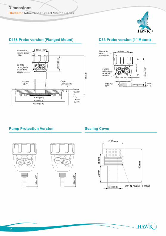
Sealing Cover
Shield SS 304
PTFE Insulation
Sense Disc SS 304
8 Nos, EQ Spaced 12mm
Depth 7mm (0.28”)
8mm(0.31”)
14mm(0.55”)
168 (6.6”) 200 (7.9”)228 (9.0”)
42mm(1.7”)
Window forviewing statusLEDs
2 x M20 cable glandsor 3/4” NPT adaptors
85mm (3.3”)
90m
m (3
.5”)
188
(7.4
”)
Window forviewing status LEDs
2 x M20 cable glandsor 3/4” NPT adaptors
85mm (3.3”)
90m
m (3
.5”)
23mm (0.91”)1” BSP or NPT
143m
m (5
.6”)
28mm (1.1”)
D33 Probe version (1” Mount)D168 Probe version (Flanged Mount)

11
MountingGladiator Admittance Smart Switch Series
Probes can be mounted from the top, side and bottom.
Points to consider when mounting:
A. Material infeed clearance
Install the probe away from the infeed to minimize the influence of build-up and impact forces, and to avoid false triggering from product flow.
B. Wall clearance
Install the probe far enough away from the wall to prevent the probe or cable from coming into contact with the vessel wall. Avoid creating a confined area where material could build-up over time.
See note
C. Nozzle clearance
Where possible, ensure the probe guard has at least 100mm clearance from the nozzle.
D. Top mounting
When top mounting, ensure adequate clearance is provided between probe and wall. Avoid creating a confined area where material could build-up over time. In the case of cable probe versions, ensure enough clearance is provided between the probe and wall to allow for build-up of material occurring on the wall.
See note
E. Side mounting
It is highly recommended to install any side mounted probe at a downward angle of 30-45º. Use a protection plate for side mounting where the probe may be subject to impact strain or collapsing material.
F. Bottom mounting
Bottom mounting is not recommended. Only mount from the bottom if no build-up of material occurs. If low level mounting is required, suitable options are shown in the diagram on page 11.
CORRECT MOUNTING NOTES:(Refer to picture on page 11)
Select correct probe for high temperature applications.
Allow adequate air flow for cooling extensions dissipate heat.
INCORRECT MOUNTING NOTES:
Incorrect mounting because the probe is too close to the wall or roof. Positioning too close to a wall or roof will limit probe sensitivity. Material may build-up between the probe and the vessel.
Incorrect mounting because the probe’s guard is mounted inside the nozzle. The correct arrangement is for the guard to protrude out of the mounting pipe at least 100mm. Product will build- up in the nozzle.
Recommended 50mm (2”)
Correct Mounting in a Nozzle
min. 100mm (4”)
Mounting
12
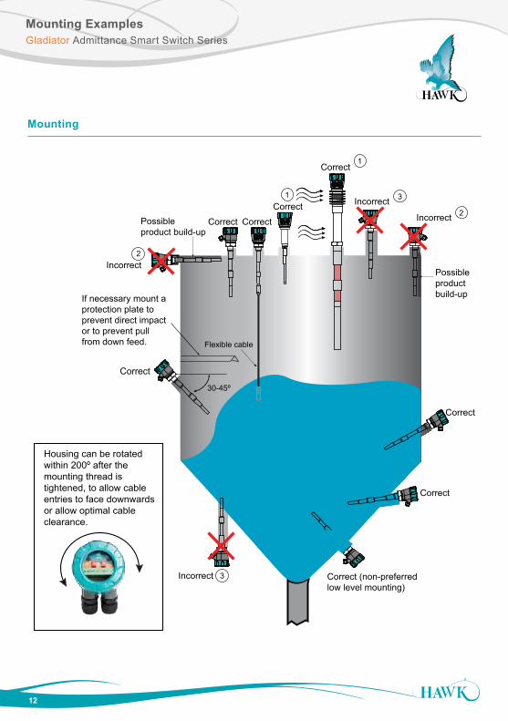
Mounting ExamplesGladiator Admittance Smart Switch Series
Mounting
Housing can be rotated within 200º after the mounting thread is tightened, to allow cableentries to face downwards or allow optimal cable clearance.
Incorrect
Correct Correct
Correct
Correct
Correct (non-preferred low level mounting)
Correct
Incorrect2
3Correct
Correct
3
If necessary mount aprotection plate to prevent direct impactor to prevent pullfrom down feed. Flexible cable
Incorrect2 Incorrect
1
30-45º
1
Possible product build-up
Possible product build-up
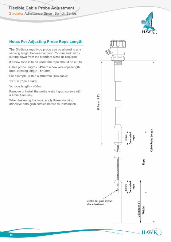
Flexible Cable Probe AdjustmentGladiator Admittance Smart Switch Series
13
Notes For Adjusting Probe Rope Length
The Gladiator rope type probe can be altered to any sensing length between approx. 750mm and 3m by cutting down from the standard sizes as required.
If a new rope is to be used, the rope should be cut to:
Cable probe length - 549mm = new wire rope length (total sensing length - 549mm)
For example, within a 1000mm (1m) cable:
1000 = [rope + 549]
So rope length = 451mm
Remove or install the probe weight grub screws with a 4mm Allen key.
When fastening the rope, apply thread-locking adhesive onto grub screws before re-installation.
Wei
ght
Removable SS grub screwsfor cable adjustment
Rope
Conc
eale
d ro
peCo
ncea
led
rope
250m
m (9
.8”)
83m
m83
mm
465m
m (1
8.3”
)
Cabl
e Pr
obe
Leng
th
14
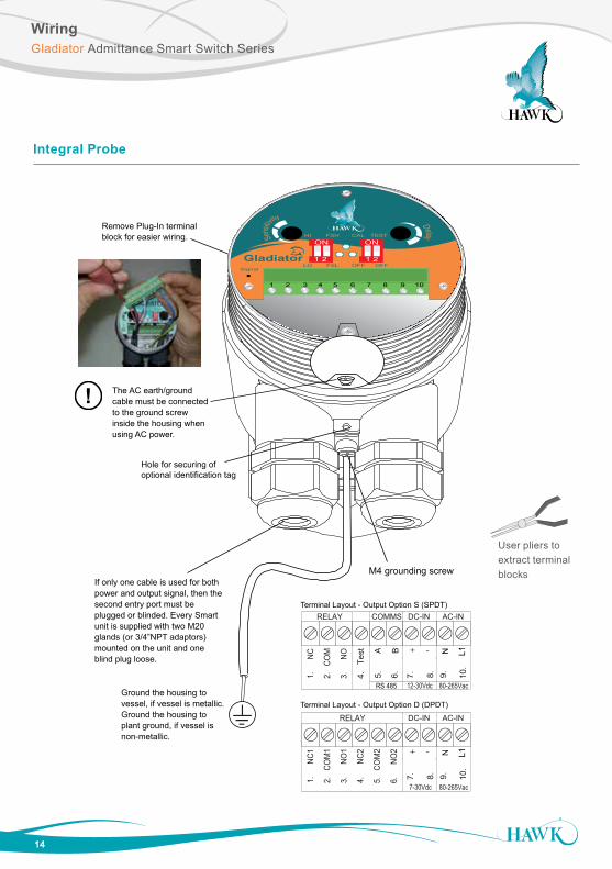
WiringGladiator Admittance Smart Switch Series
Integral Probe
User pliers to extract terminal blocks
1 2 3 4 5 6 7 8 9 10
SENSIT
IVIT
Y
DELAY
HI FSH TESTCAL
1.
NC
RELAY
2.
COM
3.
NO
COMMS DC-IN AC-IN
4.
Test
12-30Vdc 80-265Vac
+7.
8.
N9.
L110
.
RS 485
5.
B
6.
A -
Terminal Layout - Output Option S (SPDT)
Hole for securing of optional identification tag
M4 grounding screw
Ground the housing to vessel, if vessel is metallic.Ground the housing to plant ground, if vessel is non-metallic.
The AC earth/ground cable must be connected to the ground screw inside the housing when using AC power.
If only one cable is used for bothpower and output signal, then the second entry port must be plugged or blinded. Every Smart unit is supplied with two M20 glands (or 3/4”NPT adaptors) mounted on the unit and one blind plug loose.
Remove Plug-In terminal block for easier wiring.
!
Terminal Layout - Output Option D (DPDT)
1.
NC
1
RELAY
2.
COM
1
3.
NO
1
DC-IN AC-IN
7-30Vdc 80-265Vac
+7.
8.
N9.
L110
.
-
4.
NC
2
5.
COM
2
6.
NO
2
Del ayFSHHI
LO FSL
CAL TEST
OFF OFFSignal
Sensi
tivity
ON
1 2
ON
1 2
1 2 3 4 5 6 7 8 9 10
15
WiringGladiator Admittance Smart Switch Series
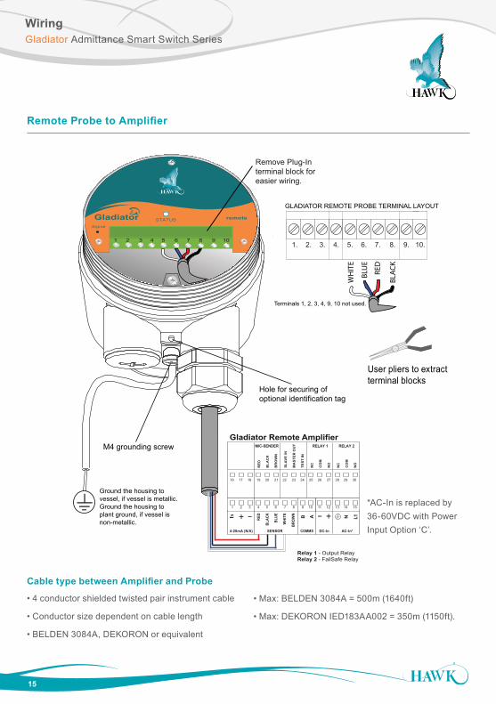
Remote Probe to Amplifier
User pliers to extract terminal blocks
Cable type between Amplifier and Probe
• 4 conductor shielded twisted pair instrument cable
• Conductor size dependent on cable length
• BELDEN 3084A, DEKORON or equivalent
• Max: BELDEN 3084A = 500m (1640ft)
• Max: DEKORON IED183AA002 = 350m (1150ft).
1 2 3 4 5 6 7 8 9 10
GLADIATOR REMOTE PROBE TERMINAL LAYOUT
M4 grounding screw
7. 1. 2. 3. 4. 5. 6. 8. 9. 10.
RED
WH
ITE
BLU
E
BLA
CK
Cable type between Amplifier and Probe4 conductor shielded twisted pair instrument cable.Conductor size dependent on cable length. BELDEN 3084A, DEKORON or equivalent.Max: BELDEN 3084A = 500m (1640ft)Max: DEKORON IED183AA002 = 350m (1150ft)
Hole for securing of optional identification tag
Ground the housing to vessel, if vessel is metallic.Ground the housing to plant ground, if vessel is non-metallic.
Remove Plug-Interminal block for easier wiring.
Terminals 1, 2, 3, 4, 9, 10 not used.
Gladiator Remote Amplifier
Relay 1 - Output RelayRelay 2 - FailSafe Relay
+ – A 1L+– NBRED
BLAC
K
BLUE
WHI
TE
BRO
WNIs
SENSOR DC-In AC-In*4-20mA (N/A) COMMS
MIC-SENDER
RE
D
BLA
CK
BR
OW
N
SLA
VE
IN
MA
STE
R O
UT
TEST
IN
RELAY 1
NC
CO
M
NO
RELAY 2
NC
CO
M
NO
1 2 3 4 5 6 7 8 9 10 11 12 13 14 15
16 17 18 19 20 21 22 23 24 25 26 27 28 29 30
remote
Signal
STATUS
1 2 3 4 5 6 7 8 9 10
*AC-In is replaced by 36-60VDC with Power Input Option ‘C’.
16
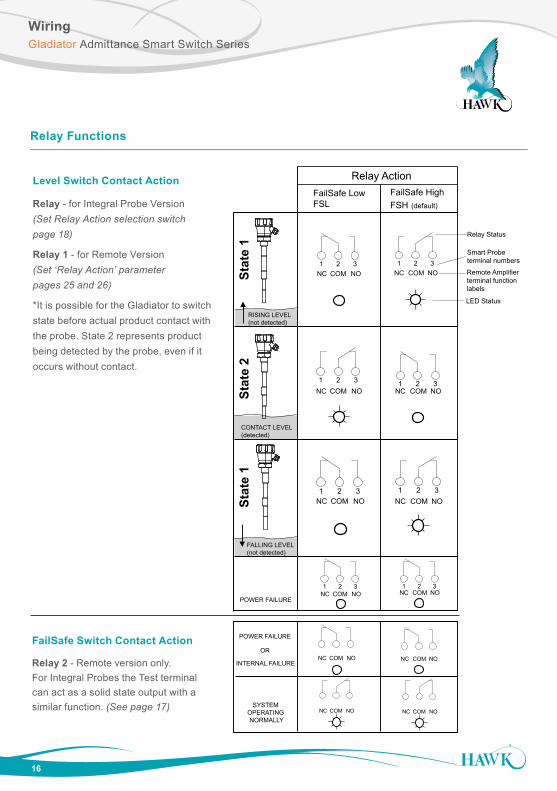
WiringGladiator Admittance Smart Switch Series
Relay Functions
HI
OFF
TEST
LOW
EN
DEN
CAL
OFF
DELAYSENSITIVITY
1 2 3
1 2 3
1 2 3
1 2 3
1 2 3
1 2 3
1 2 3
1 2 3
RISING LEVEL(not detected)
CONTACT LEVEL(detected)
FALLING LEVEL(not detected)
NC NO
NC NO
NC NO
NC NO
NC NO
NC NO
NC NO
NC NO
COMMS DC-IN
AC
GN
D to
met
al c
ase
12-30VDC
+7.
8.
RS 485
5.
B
6.
A
1 2 3 4 5 6 7 8 9 10
+ –4-20mA
AC-IN
A 1L+–
DC-IN4-20mA COMMSTRANSDUCER
NB
RELAY 1
NC COM
NO
RELAY 2
NC COM
NO
RELAY 3
NC COM
NO
RELAY 4
NC COM
NO
RELAY 5
NC COM
NO
Test
inIs
RED
BLAC
K
BLUE
WHI
TE
REMOTE AMPLIFIER
GLADIATOR TERMINAL
COM COM
COM COM
COM COM
COM COMPOWER FAILURE
NC NO NC NOCOM COMINTERNAL FAILURE
POWER FAILURE
OR
SYSTEM OPERATING NORMALLY
NC NOCOM NC NOCOM
Stat
e 1
Stat
e 2
Stat
e 1
Smart Probe terminal numbers
Remote Amplifier terminal function labels
FailSafe LowFSL
FailSafe HighFSH (default)
Relay Status
LED Status
Relay Action
FailSafe Switch Contact Action
Relay 2 - Remote version only. For Integral Probes the Test terminal can act as a solid state output with a similar function. (See page 17)
Level Switch Contact Action
Relay - for Integral Probe Version (Set Relay Action selection switch page 18)
Relay 1 - for Remote Version (Set ‘Relay Action’ parameter pages 25 and 26)
*It is possible for the Gladiator to switch state before actual product contact with the probe. State 2 represents product being detected by the probe, even if it occurs without contact.
17
WiringGladiator Admittance Smart Switch Series
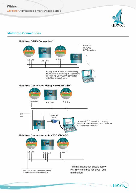
Multidrop Connections
Laptop or PC Communications usingPCMCIA card or wired (PSTN) modemand remote GSM/CDMA connection with GosHawk software.
A B Gnd A B Gnd A B Gnd
Laptop or PC Communications usingHawkLink USB or RS485 / 232 converterwith GosHawk software.
HawkLinkUSB
A B GndA B Gnd A B Gnd
PLC / DCS / SCADA for Remote Communication with Modbus.
A B Gnd A B Gnd A B Gnd
HawkLink HLRUG6GPRS modem
WhiteBlueBlack
Multidrop Connection Using HawkLink USB*
Multidrop GPRS Connection*
Multidrop Connection to PLC/DCS/SCADA*
* Wiring installation should follow RS-485 standards for layout and termination.
DelayFSHHI
LO FSL
CAL TEST
OFF OFFSignal
Sens
itiv
ity
ON
1 2
ON
1 2
1 2 3 4 5 6 7 8 9 10
DelayFSHHI
LO FSL
CAL TEST
OFF OFFSignal
Sens
itiv
ity
ON
1 2
ON
1 2
1 2 3 4 5 6 7 8 9 10
CAL
RUN
RELAY 1 RELAY 2 STATUS A STATUS B
DelayFSHHI
LO FSL
CAL TEST
OFF OFFSignal
Sens
itiv
ity
ON
1 2
ON
1 2
1 2 3 4 5 6 7 8 9 10
DelayFSHHI
LO FSL
CAL TEST
OFF OFFSignal
Sens
itiv
ity
ON
1 2
ON
1 2
1 2 3 4 5 6 7 8 9 10
CAL
RUN
RELAY 1 RELAY 2 STATUS A STATUS B
CAL
RUN
LINK
CAL
RUN
LINK
DelayFSHHI
LO FSL
CAL TEST
OFF OFFSignal
Sens
itiv
ity
ON
1 2
ON
1 2
1 2 3 4 5 6 7 8 9 10
DelayFSHHI
LO FSL
CAL TEST
OFF OFFSignal
Sens
itiv
ity
ON
1 2
ON
1 2
1 2 3 4 5 6 7 8 9 10
CAL
RUN
RELAY 1 RELAY 2 STATUS A STATUS B
18
WiringGladiator Admittance Smart Switch Series
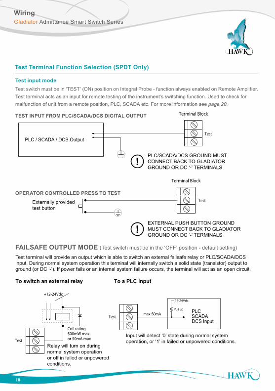
Test Terminal Function Selection (SPDT Only)
Terminal Block
PLC / SCADA / DCS OutputTest
Terminal Block
Test
Test
Coil rating 500mW maxor 50mA max
Test
To switch an external relay
+12-24Vdc
PLCSCADA DCS Input
Pull up
12-24Vdc
max 50mA
To a PLC input
Externally provided test button
!
!
PLC/SCADA/DCS GROUND MUSTCONNECT BACK TO GLADIATORGROUND OR DC ‘-’ TERMINALS
EXTERNAL PUSH BUTTON GROUNDMUST CONNECT BACK TO GLADIATORGROUND OR DC ‘-’ TERMINALS
Test terminal will provide an output which is able to switch an external failsafe relay or PLC/SCADA/DCS input. During normal system operation this terminal will internally switch a solid state (transistor) output to ground (or DC ‘-’). If power fails or an internal system failure occurs, the terminal will act as an open circuit.
Relay will turn on duringnormal system operationor off in failed or unpoweredconditions.
Input will detect ‘0’ state during normal systemoperation, or ‘1’ in failed or unpowered conditions.
Test input modeTest switch must be in ‘TEST’ (ON) position on Integral Probe - function always enabled on Remote Amplifier. Test terminal acts as an input for remote testing of the instrument’s switching function. Used to check for malfunction of unit from a remote position, PLC, SCADA etc. For more information see page 20.
TEST INPUT FROM PLC/SCADA/DCS DIGITAL OUTPUT
OPERATOR CONTROLLED PRESS TO TEST
FAILSAFE OUTPUT MODE (Test switch must be in the ‘OFF’ position - default setting)
19
Integral Probe Functionality Layout
Setup ProcedureGladiator Admittance Smart Switch Series
1
2
3
4
5
6
7
8
9
10
11
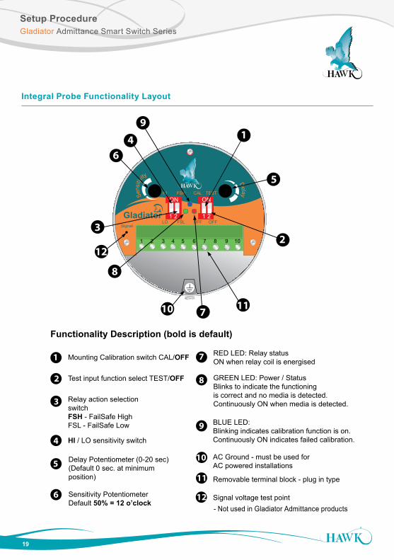
Mounting Calibration switch CAL/OFF
Relay action selectionswitch FSH - FailSafe High FSL - FailSafe Low
Sensitivity PotentiometerDefault 50% = 12 o’clock
HI / LO sensitivity switch
BLUE LED:Blinking indicates calibration function is on.Continuously ON indicates failed calibration.
AC Ground - must be used forAC powered installations
GREEN LED: Power / StatusBlinks to indicate the functioningis correct and no media is detected.Continuously ON when media is detected.
Removable terminal block - plug in type
Delay Potentiometer (0-20 sec)(Default 0 sec. at minimumposition)
Test input function select TEST/OFF
RED LED: Relay statusON when relay coil is energised
Functionality Description (bold is default)
12 Signal voltage test point
DelayFSHHI
LO FSL
CAL TEST
OFF OFFSignal
Sens
itiv
ity
1 2 3 4 5 6 7 8 9 10
ON
1 2
ON
1 2
9
4
6
3
12
8
10 711
2
5
1
- Not used in Gladiator Admittance products
20
Setup ProcedureGladiator Admittance Smart Switch Series
Integral Probe Version
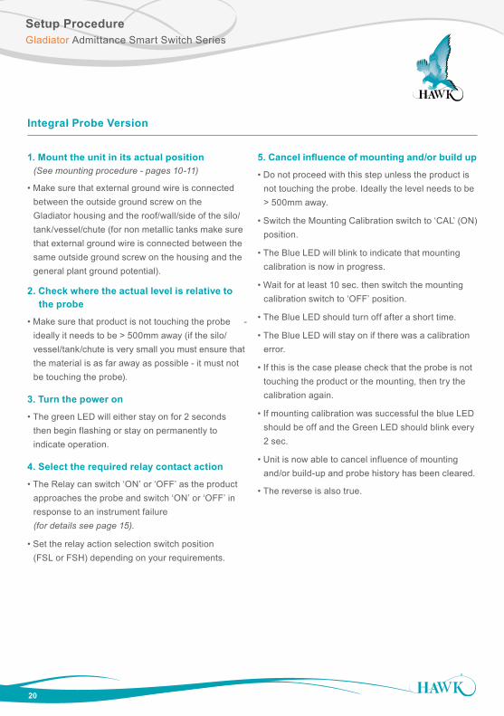
1. Mount the unit in its actual position (See mounting procedure - pages 10-11)
• Make sure that external ground wire is connected between the outside ground screw on the Gladiator housing and the roof/wall/side of the silo/ tank/vessel/chute (for non metallic tanks make sure that external ground wire is connected between the same outside ground screw on the housing and the general plant ground potential).
2. Check where the actual level is relative to the probe
• Make sure that product is not touching the probe - ideally it needs to be > 500mm away (if the silo/ vessel/tank/chute is very small you must ensure that the material is as far away as possible - it must not be touching the probe).
3. Turn the power on
• The green LED will either stay on for 2 seconds then begin flashing or stay on permanently to indicate operation.
4. Select the required relay contact action
• The Relay can switch ‘ON’ or ‘OFF’ as the product approaches the probe and switch ‘ON’ or ‘OFF’ in response to an instrument failure (for details see page 15).
• Set the relay action selection switch position (FSL or FSH) depending on your requirements.
5. Cancel influence of mounting and/or build up
• Do not proceed with this step unless the product is not touching the probe. Ideally the level needs to be > 500mm away.
• Switch the Mounting Calibration switch to ‘CAL’ (ON) position.
• The Blue LED will blink to indicate that mounting calibration is now in progress.
• Wait for at least 10 sec. then switch the mounting calibration switch to ‘OFF’ position.
• The Blue LED should turn off after a short time.
• The Blue LED will stay on if there was a calibration error.
• If this is the case please check that the probe is not touching the product or the mounting, then try the calibration again.
• If mounting calibration was successful the blue LED should be off and the Green LED should blink every 2 sec.
• Unit is now able to cancel influence of mounting and/or build-up and probe history has been cleared.
• The reverse is also true.
21
Setup ProcedureGladiator Admittance Smart Switch Series
Integral Probe Version
6. Select the sensitivity
There are two adjustments controlling the sensitivity of the switch point:
6.1. The ‘HI/LO’ sensitivity switch is used to set your unit depending on the dielectric properties of the product to be measured. This switch sets the range of adjustment possible with the sensitivity potentiometer.
• If the material to be detected has a lower dielectric constant than 10 - set the switch to ‘HI’ (ON)-default.
• If material to be detected has a higher dielectric constant than 10 - set switch to ‘LO’.
• If you are not aware of your material dielectric constant – set the switch to ‘HI’ (ON) - default.
6.2 The sensitivity potentiometer
• Set the potentiometer according to your requirements.
• A 12 o’clock setting (50%) - default, will cover the majority of instances - for the remaining instances, turning the potentiometer anti clockwise will decrease sensitivity.
• Switch point will then occur with the material nearer to the probe or more in contact with the probe than before.
7. Select the time delay• Set the required delay using the Delay potentiometer (Default is 0 sec. at minimum position).
• Turn the potentiometer clockwise if any delay is required.
• Maximum rotation is ¾ of a revolution.
• Max delay is 20 sec.
• The selected delay will be used for both an ON delay and an OFF delay.*
8. Test function (used to check for malfunction of unit from remote position, PLC, SCADA etc)• Select the desired Test function by switching the ‘Test’ switch (Default = ‘OFF’).
• TEST’ (ON) Position:
• Test function is selected.
• Test terminal (terminal number 4 of Integral probe) is used as an input to the unit.
• The test function allows you to check the functionality of the unit.
• Applying a ground wire to the Test terminal will change the state of the relay. It will hold this state until the ground is removed, then it will change back to the standard running mode.
• If the unit was in a Fail mode then the relay will not change status.
• ‘OFF’ (Default) Position:
• Fail safe output function is selected.
• Test terminal (terminal number 4 of Integral probe) will function as an open drain drive.
• This can be used to drive a relay or an active low PLC input to detect a Fail condition.
• In normal operation mode the Test terminal will output Zero Volts (Short to GND).
• In Fail or unpowered mode the Test terminal will be open circuit.
*Setting of different time ranges for the delay potentiometer for ON delay and OFF delay is possible using a PC connected via GosHawk II software. By default, both will have the same time adjustment range (20 sec max) and adjustment will result in equal ON delay and OFF delay.
22
Setup ProcedureGladiator Admittance Smart Switch Series
Remote Functionality Layout
remote
Signal
STATUS
1 2 3 4 5 6 7 8 9 108
9
8
9
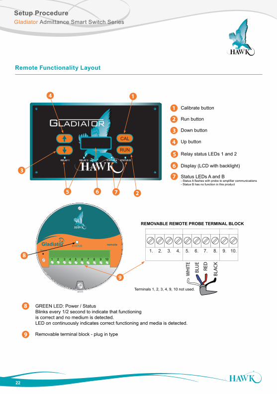
Calibrate button
Down button
Up button
Relay status LEDs 1 and 2
Run button
Removable terminal block - plug in type
CAL
RUN
RELAY 1 RELAY 2 STATUS A STATUS B
3
REMOVABLE REMOTE PROBE TERMINAL BLOCK
7. 1. 2. 3. 4. 5. 6. 8. 9. 10.
RED
WH
ITE
BLU
E
BLA
CK
Display (LCD with backlight)
Terminals 1, 2, 3, 4, 9, 10 not used.
1
2
3
4
5
6
7 Status LEDs A and B- Status A flashes with probe to amplifier communications- Status B has no function in this product
14
25 6 7
GREEN LED: Power / StatusBlinks every 1/2 second to indicate that functioningis correct and no medium is detected.LED on continuously indicates correct functioning and media is detected.
Setup ProcedureGladiator Admittance Smart Switch Series
23
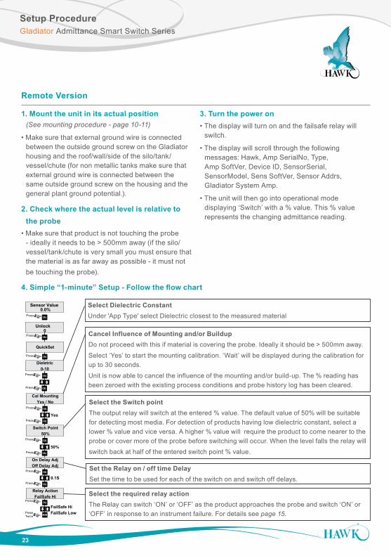
Remote Version
1. Mount the unit in its actual position (See mounting procedure - page 10-11)
• Make sure that external ground wire is connected between the outside ground screw on the Gladiator housing and the roof/wall/side of the silo/tank/ vessel/chute (for non metallic tanks make sure that external ground wire is connected between the same outside ground screw on the housing and the general plant ground potential.).
2. Check where the actual level is relative to the probe• Make sure that product is not touching the probe - ideally it needs to be > 500mm away (if the silo/ vessel/tank/chute is very small you must ensure that the material is as far away as possible - it must not be touching the probe).
3. Turn the power on• The display will turn on and the failsafe relay will switch.
• The display will scroll through the following messages: Hawk, Amp SerialNo, Type, Amp SoftVer, Device ID, SensorSerial, SensorModel, Sens SoftVer, Sensor Addrs, Gladiator System Amp.
• The unit will then go into operational mode displaying ‘Switch’ with a % value. This % value represents the changing admittance reading.
4. Simple “1-minute” Setup - Follow the flow chart
Select the Switch point The output relay will switch at the entered % value. The default value of 50% will be suitable for detecting most media. For detection of products having low dielectric constant, select a lower % value and vice versa. A higher % value will require the product to come nearer to the probe or cover more of the probe before switching will occur. When the level falls the relay will switch back at half of the entered switch point % value.
Set the Relay on / off time DelaySet the time to be used for each of the switch on and switch off delays.
Cancel Influence of Mounting and/or BuildupDo not proceed with this if material is covering the probe. Ideally it should be > 500mm away.Select ‘Yes’ to start the mounting calibration. ‘Wait’ will be displayed during the calibration for up to 30 seconds.Unit is now able to cancel the influence of the mounting and/or build-up. The % reading has been zeroed with the existing process conditions and probe history log has been cleared.
Select the required relay actionThe Relay can switch ‘ON’ or ‘OFF’ as the product approaches the probe and switch ‘ON’ or ‘OFF’ in response to an instrument failure. For details see page 15.
Select Dielectric ConstantUnder 'App Type' select Dielectric closest to the measured material
QuickSet
Cal MountingYes / No
Relay ActionFailSafe Hi
Unlock0
Sensor Value0.0%
CAL
CALPress
Press
CAL
CAL
CAL
Press
Press
Press
Press CAL
CALPress
CAL
CAL
CAL
RUN
Press
Press
Press
PressTwice
Switch Point50%
On Delay AdjOff Delay Adj
Yes
50%
0.1S
FailSafe HiFailSafe Low
Dieletric0-10
Press CAL
CALPress
QuickSet
Unlock0
Sensor Value0.0%
CAL
CALPress
Press
Advanced
CAL
RUN
24
Main Menu & InterfaceGladiator Admittance Smart Switch Series
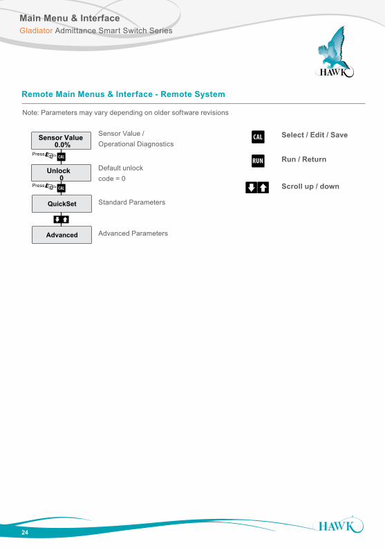
Select / Edit / Save
Run / Return
Scroll up / down
Remote Main Menus & Interface - Remote System
Note: Parameters may vary depending on older software revisions
QuickSet
Cal MountingYes / No
Relay ActionFailSafe Hi
Unlock0
Sensor Value0.0%
CAL
CALPress
Press
CAL
CAL
CAL
Press
Press
Press
Press CAL
CALPress
CAL
CAL
CAL
RUN
Press
Press
Press
PressTwice
Switch Point50%
On Delay AdjOff Delay Adj
Yes
50%
0.1S
FailSafe HiFailSafe Low
Dieletric0-10
Press CAL
CALPress
QuickSet
Unlock0
Sensor Value0.0%
CAL
CALPress
Press
Advanced
CAL
RUN
QuickSet
Cal MountingYes / No
Relay ActionFailSafe Hi
Unlock0
Sensor Value0.0%
CAL
CALPress
Press
CAL
CAL
CAL
Press
Press
Press
Press CAL
CALPress
CAL
CAL
CAL
RUN
Press
Press
Press
PressTwice
Switch Point50%
On Delay AdjOff Delay Adj
Yes
50%
0.1S
FailSafe HiFailSafe Low
Dieletric0-10
Press CAL
CALPress
QuickSet
Unlock0
Sensor Value0.0%
CAL
CALPress
Press
Advanced
CAL
RUN
Sensor Value / Operational Diagnostics
Default unlock code = 0
Standard Parameters
Advanced Parameters
25
Software ParametersGladiator Admittance Smart Switch Series
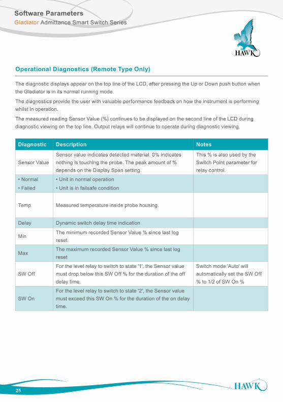
Operational Diagnostics (Remote Type Only)
The diagnostic displays appear on the top line of the LCD, after pressing the Up or Down push button when the Gladiator is in its normal running mode.
The diagnostics provide the user with valuable performance feedback on how the instrument is performing whilst in operation.
The measured reading Sensor Value (%) continues to be displayed on the second line of the LCD during diagnostic viewing on the top line. Output relays will continue to operate during diagnostic viewing.
Diagnostic Description Notes
Sensor ValueSensor value indicates detected material. 0% indicates nothing is touching the probe. The peak amount of % depends on the Display Span setting.
This % is also used by the Switch Point parameter for relay control.
• Normal
• Failed
• Unit in normal operation
• Unit is in failsafe condition
Temp Measured temperature inside probe housing.
Delay Dynamic switch delay time indication
MinThe minimum recorded Sensor Value % since last log reset
MaxThe maximum recorded Sensor Value % since last log reset
SW OffFor the level relay to switch to state '1', the Sensor value must drop below this SW Off % for the duration of the off delay time.
Switch mode 'Auto' will automatically set the SW Off % to 1/2 of SW On %
SW OnFor the level relay to switch to state '2', the Sensor value must exceed this SW On % for the duration of the on delay time.
26
Software ParametersGladiator Admittance Smart Switch Series
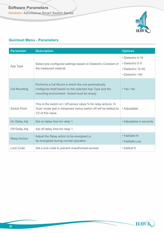
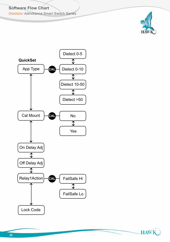
Parameter Description Options
App TypeSelect pre-configured settings based on Dielectric Constant of the measured material
• Dielectric 0-10
• Dielectric 0-5
• Dielectric 10-50
• Dielectric >50
Cal MountingPerforms a Cal Mount in which the unit automatically configures itself based on the selected App Type and the mounting environment. Vessel must be empty.
• Yes / No
Switch PointThis is the switch on / off sensor value % for relay actions. In 'Auto' mode (set in Advanced menu) switch off will be default to 1/2 of this value.
• Adjustable
On Delay Adj Set on delay time for relay 1. • Adjustable in seconds
Off Delay Adj Set off delay time for relay 1.
Relay1ActionAdjust the Relay action to be energised or de-energised during normal operation
• FailSafe Hi
• FailSafe Low
Lock Code Set a lock code to prevent unauthorised access • Default 0
Quickset Menu - Parameters
27
Software ParametersGladiator Admittance Smart Switch Series
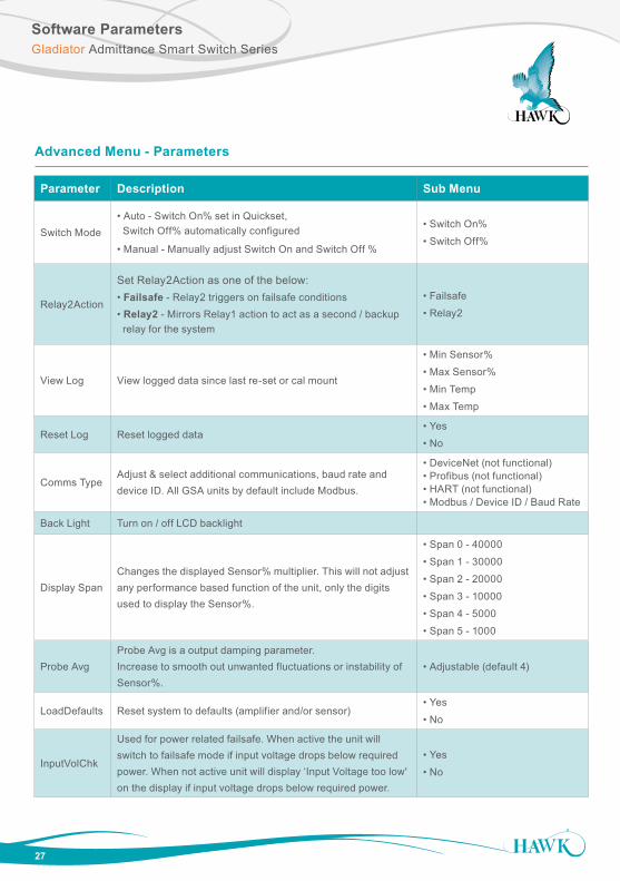
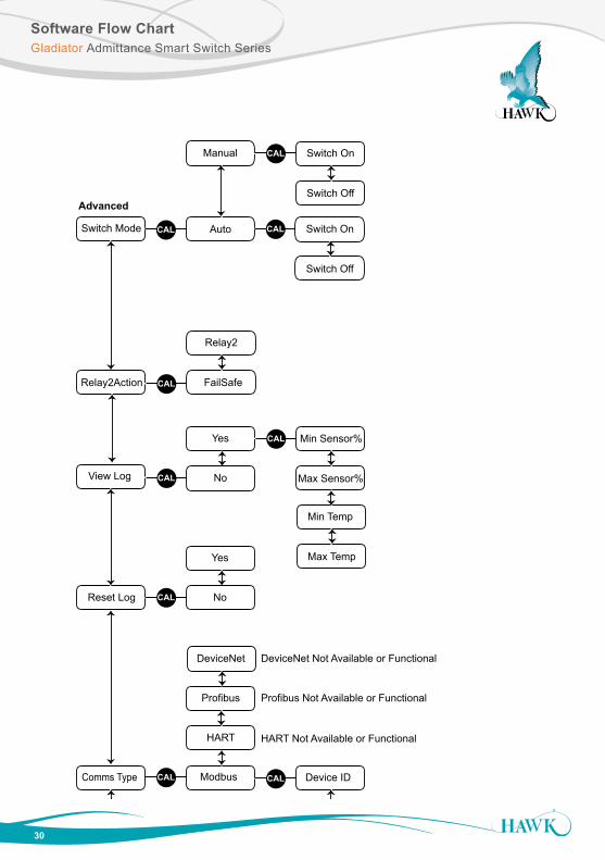
Parameter Description Sub Menu
Switch Mode• Auto - Switch On% set in Quickset, Switch Off% automatically configured
• Manual - Manually adjust Switch On and Switch Off %
• Switch On%
• Switch Off%
Relay2Action
Set Relay2Action as one of the below:• Failsafe - Relay2 triggers on failsafe conditions• Relay2 - Mirrors Relay1 action to act as a second / backup relay for the system
• Failsafe
• Relay2
View Log View logged data since last re-set or cal mount
• Min Sensor%
• Max Sensor%
• Min Temp
• Max Temp
Reset Log Reset logged data• Yes
• No
Comms TypeAdjust & select additional communications, baud rate and device ID. All GSA units by default include Modbus.
• DeviceNet (not functional)• Profibus (not functional)• HART (not functional)• Modbus / Device ID / Baud Rate
Back Light Turn on / off LCD backlight
Display SpanChanges the displayed Sensor% multiplier. This will not adjust any performance based function of the unit, only the digits used to display the Sensor%.
• Span 0 - 40000
• Span 1 - 30000
• Span 2 - 20000
• Span 3 - 10000
• Span 4 - 5000
• Span 5 - 1000
Probe AvgProbe Avg is a output damping parameter. Increase to smooth out unwanted fluctuations or instability of Sensor%.
• Adjustable (default 4)
LoadDefaults Reset system to defaults (amplifier and/or sensor)• Yes
• No
InputVolChk
Used for power related failsafe. When active the unit will switch to failsafe mode if input voltage drops below required power. When not active unit will display ‘Input Voltage too low' on the display if input voltage drops below required power.
• Yes
• No
Advanced Menu - Parameters
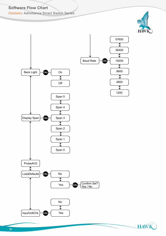
Software Flow ChartGladiator Admittance Smart Switch Series
28
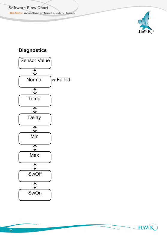
Diagnostics
Sensor Value
Normal or Failed
App Type
Cal Mount
CAL Dielect 0-10
View Log
Reset Log
CAL
Yes
No
QuickSet
Comms Type CAL Modbus
HART
Back Light
LoadDefaults CAL No
Yes CAL Confirm Sel?Yes / No
Dielect 0-5
Temp
Delay
Min
Max
SwOff
SwOn
Dielect 10-50
Dielect >50
CAL
Yes
No
On Delay Adj
Off Delay Adj
Relay1Action CAL
FailSafe Lo
FailSafe Hi
Lock Code
Switch Mode CAL Auto
Advanced
Manual
CAL
CAL
Switch Off
Switch On
Switch Off
Switch On
Relay2Action CAL FailSafe
Relay2
CAL
Max Sensor%
Min Sensor%
Max Temp
Min Temp
CAL
Yes
No
CAL
Baud Rate
Device ID
Profibus
DeviceNet DeviceNet Not Available or Functional
Profibus Not Available or Functional
HART Not Available or Functional
CAL 19200
38400
57600
1200
4800
9600CAL On
Off
Display Span CAL Span 3
Span 4
Span 5
Span 0
Span 1
Span 2
ProbeAVG
InputVoltChk CAL
No
Yes
Software Flow ChartGladiator Admittance Smart Switch Series
29
Diagnostics
Sensor Value
Normal or Failed
App Type
Cal Mount
CAL Dielect 0-10
View Log
Reset Log
CAL
Yes
No
QuickSet
Comms Type CAL Modbus
HART
Back Light
LoadDefaults CAL No
Yes CAL Confirm Sel?Yes / No
Dielect 0-5
Temp
Delay
Min
Max
SwOff
SwOn
Dielect 10-50
Dielect >50
CAL
Yes
No
On Delay Adj
Off Delay Adj
Relay1Action CAL
FailSafe Lo
FailSafe Hi
Lock Code
Switch Mode CAL Auto
Advanced
Manual
CAL
CAL
Switch Off
Switch On
Switch Off
Switch On
Relay2Action CAL FailSafe
Relay2
CAL
Max Sensor%
Min Sensor%
Max Temp
Min Temp
CAL
Yes
No
CAL
Baud Rate
Device ID
Profibus
DeviceNet DeviceNet Not Available or Functional
Profibus Not Available or Functional
HART Not Available or Functional
CAL 19200
38400
57600
1200
4800
9600CAL On
Off
Display Span CAL Span 3
Span 4
Span 5
Span 0
Span 1
Span 2
ProbeAVG
InputVoltChk CAL
No
Yes
Software Flow ChartGladiator Admittance Smart Switch Series
30
Diagnostics
Sensor Value
Normal or Failed
App Type
Cal Mount
CAL Dielect 0-10
View Log
Reset Log
CAL
Yes
No
QuickSet
Comms Type CAL Modbus
HART
Back Light
LoadDefaults CAL No
Yes CAL Confirm Sel?Yes / No
Dielect 0-5
Temp
Delay
Min
Max
SwOff
SwOn
Dielect 10-50
Dielect >50
CAL
Yes
No
On Delay Adj
Off Delay Adj
Relay1Action CAL
FailSafe Lo
FailSafe Hi
Lock Code
Switch Mode CAL Auto
Advanced
Manual
CAL
CAL
Switch Off
Switch On
Switch Off
Switch On
Relay2Action CAL FailSafe
Relay2
CAL
Max Sensor%
Min Sensor%
Max Temp
Min Temp
CAL
Yes
No
CAL
Baud Rate
Device ID
Profibus
DeviceNet DeviceNet Not Available or Functional
Profibus Not Available or Functional
HART Not Available or Functional
CAL 19200
38400
57600
1200
4800
9600CAL On
Off
Display Span CAL Span 3
Span 4
Span 5
Span 0
Span 1
Span 2
ProbeAVG
InputVoltChk CAL
No
Yes
Software Flow ChartGladiator Admittance Smart Switch Series
31
Diagnostics
Sensor Value
Normal or Failed
App Type
Cal Mount
CAL Dielect 0-10
View Log
Reset Log
CAL
Yes
No
QuickSet
Comms Type CAL Modbus
HART
Back Light
LoadDefaults CAL No
Yes CAL Confirm Sel?Yes / No
Dielect 0-5
Temp
Delay
Min
Max
SwOff
SwOn
Dielect 10-50
Dielect >50
CAL
Yes
No
On Delay Adj
Off Delay Adj
Relay1Action CAL
FailSafe Lo
FailSafe Hi
Lock Code
Switch Mode CAL Auto
Advanced
Manual
CAL
CAL
Switch Off
Switch On
Switch Off
Switch On
Relay2Action CAL FailSafe
Relay2
CAL
Max Sensor%
Min Sensor%
Max Temp
Min Temp
CAL
Yes
No
CAL
Baud Rate
Device ID
Profibus
DeviceNet DeviceNet Not Available or Functional
Profibus Not Available or Functional
HART Not Available or Functional
CAL 19200
38400
57600
1200
4800
9600CAL On
Off
Display Span CAL Span 3
Span 4
Span 5
Span 0
Span 1
Span 2
ProbeAVG
InputVoltChk CAL
No
Yes
32
TroubleshootingGladiator Admittance Smart Switch Series
Remote Version
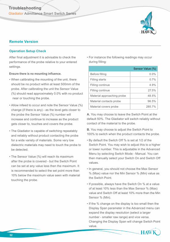
Operation Setup Check
After final adjustment it is advisable to check the performance of the probe relative to your entered settings.
Ensure there is no mounting influence.
• When calibrating the mounting of the unit, there should be no product within at least 500mm of the probe. After calibrating the unit the Sensor Value (%) should read approximately 0.0% with no product near or touching the probe.
• Allow infeed to occur and note the Sensor Value (%) change (if there is any) - as the level gets closer to the probe the Sensor Value (%) number will increase and continue to increase as the product gets closer to, touches and covers the probe.
• The Gladiator is capable of switching repeatably and reliably without product contacting the probe for a wide variety of materials. Some very low dielectric materials may need to touch the probe to be detected.
• The Sensor Value (%) will reach its maximum after the probe is covered - but the Switch Point can be set at any value less then the maximum. It is recommended to select the set point more than 10% below the maximum value seen with material touching the probe.
• For instance the following readings may occur during filling:
A. You may choose to leave the Switch Point at the default 50%. The Gladiator will switch reliably without contact of the material to the probe.
B. You may choose to adjust the Switch Point to 100% to switch when the product contacts the probe.
• By default the Switch Off % is set at 1/2 of the Switch Point. You may wish to adjust this to a higher or lower number. This is adjustable in the Advanced Menu by selecting Switch Mode - Manual. You can then manually select your Switch On and Switch Off values.
• In general, you should not choose the Max Sensor % (Max) value nor the Min Sensor % (Min) value as the Switch Point.
• If possible, always have the Switch On % at a value of at least 10% less than the Max Sensor % (Max) value and Switch Off at least 10% more than the Min Sensor % (Min).
• If the % change on the display is too small then the Display Span parameter in the Advanced menu can expand the display resolution (select a larger number - smaller raw range) and vice versa. Changing the Display Span will change Switch Point value.
Sensor Value (%)
Before filling 0.0%
Filling starts 0.7%
Filling continue 4.9%
Filling continue 27.5%
Material approaching probe 48.5%
Material contacts probe 96.5%
Material covers probe 285.7%
Part NumberingGladiator Admittance Smart Switch Series
33
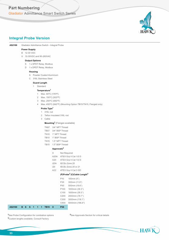
Integral Probe Version
AS2100 Gladiator Admittance Switch - Integral Probe
Power Supply
B 12-30 VDC
U 12-30VDC and 90-260VAC
Output Options S 1 x SPDT Relay, Modbus
D 1 x DPDT Relay, Modbus
Housing
S Powder Coated Aluminium
C 316L Stainless Steel
Guard Length
1 Standard
Temperature1
1 Max. 80ºC (176ºF)
2 Max. 150ºC (302ºF)
3 Max. 250ºC (482ºF)
4 Max. 450ºC (842ºF) (Mounting Option TB15/TN15, Flanged only)
Probe Type1
1 316L rod
2 Teflon Insulated 316L rod
3 Cable
Mounting1 (Flanges available)
TN07 3/4” NPT Thread
TB07 3/4” BSP Thread
TN10 1” NPT Thread
TB10 1” BSP Thread
TN15 1.5” NPT Thread
TB15 1.5” BSP Thread
Approvals2
X Not Required
A20A ATEX Grp II Cat 1/2 D
A20 ATEX Grp II Cat 1/2 D
i20A IECEx Zone 20
i20 IECEx Zone 20 or 21
A22 ATEX Grp II Cat 3 GD
(P)Probe3 (C)Cable Length3
P10 100mm (4”)
P30 300mm (11.8”)
P50 500mm (19.6”)
P100 1000mm (39.3”)
C100 1000mm (39.3”)
C200 2000mm (78.7”)
C300 3000mm (118.1”)
C500 5000mm (196.9”)
AS2100 B S S 1 1 1 TB15 X P30
1See Probe Configuration for combiation options 2See Approvals Section for critical details 3Custom lengths available. Consult Factory
34
Part NumberingGladiator Admittance Smart Switch Series
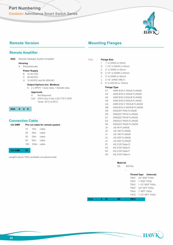
Remote Version
Remote Amplifier
GSA Remote Gladiator System Amplifier
Housing S Polycarbonate
Power Supply B 12-30 VDC C 36-60VDC U 12-30VDC and 90-260VAC
Output Options (inc. Modbus) S 2 x SPDT, 1 level relay, 1 failsafe relay
Approvals X Not Required A22 ATEX Grp II Cat 3 GD T75°C IP67 Tamb -40°C to 65°C
GSA S U S
CA-GMR Pre-cut cable for remote system
10 10m cable
20 20m cable
30 30m cable
50 50m cable
100 100m cable
CA-GMR 10
Connection Cable
Lengths above 100m available via special order
FLA - Flange Size 1 1” or DN25 or 25mm H 1 1/2” or DN40 or 40mm 2 2” or DN50 or 50mm K 2 1/2” or DN65 or 65mm 3 3” or DN80 or 80mm L 3 1/2” (ANSI ONLY) 4 4” or DN100 or 100mm
Flange Type A1 ANSI B16.5 150LB FLANGE A3 ANSI B16.5 300LB FLANGE A6 ANSI B16.5 600LB FLANGE A9 ANSI B16.5 900LB FLANGE AA ANSI B16.5 1500LB FLANGE AB ANSI B16.5 2500LB FLANGE D6 DIN2527 PN6 FLANGE D0 DIN2527 PN10 FLANGE D1 DIN2527 PN16 FLANGE D2 DIN2527 PN25 FLANGE D4 DIN2527 PN40 FLANGE J5 JIS 5K FLANGE J0 JIS 10K FLANGE J1 JIS 16K FLANGE J2 JIS 20K FLANGE J4 JIS 40K FLANGE S1 AS 2129 Table D S2 AS 2129 Table E S3 AS 2129 Table F S4 AS 2129 Table H
-
Material SS SS316L
-
Thread Type (internal) TB07 3/4” BSP THDs TB10 1” BSP THDs TB15 1 1/2” BSP THDs TN07 3/4” NPT THDs TN10 1” NPT THDs TN15 1 1/2” NPT THDs
FLA - 2 A1 - SS - TB15
Mounting Flanges
Part NumberingGladiator Admittance Smart Switch Series
35
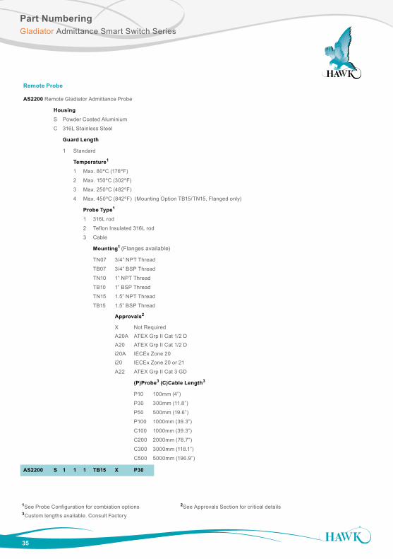
Remote Probe
AS2200 Remote Gladiator Admittance Probe
Housing
S Powder Coated Aluminium
C 316L Stainless Steel
Guard Length
1 Standard
Temperature1
1 Max. 80ºC (176ºF)
2 Max. 150ºC (302ºF)
3 Max. 250ºC (482ºF)
4 Max. 450ºC (842ºF) (Mounting Option TB15/TN15, Flanged only)
Probe Type1
1 316L rod
2 Teflon Insulated 316L rod
3 Cable
Mounting1 (Flanges available)
TN07 3/4” NPT Thread
TB07 3/4” BSP Thread
TN10 1” NPT Thread
TB10 1” BSP Thread
TN15 1.5” NPT Thread
TB15 1.5” BSP Thread
Approvals2
X Not Required
A20A ATEX Grp II Cat 1/2 D
A20 ATEX Grp II Cat 1/2 D
i20A IECEx Zone 20
i20 IECEx Zone 20 or 21
A22 ATEX Grp II Cat 3 GD
(P)Probe3 (C)Cable Length3
P10 100mm (4”)
P30 300mm (11.8”)
P50 500mm (19.6”)
P100 1000mm (39.3”)
C100 1000mm (39.3”)
C200 2000mm (78.7”)
C300 3000mm (118.1”)
C500 5000mm (196.9”)
AS2200 S 1 1 1 TB15 X P30
1See Probe Configuration for combiation options 2See Approvals Section for critical details 3Custom lengths available. Consult Factory
Part NumberingGladiator Admittance Smart Switch Series
36
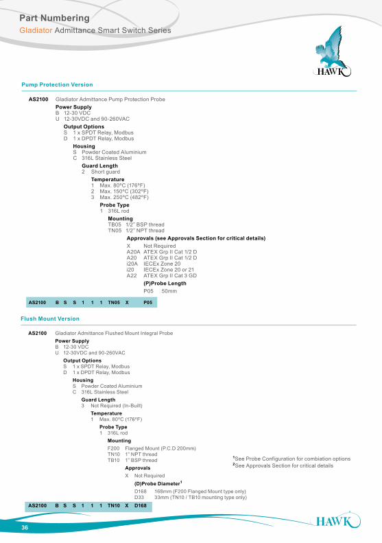
Pump Protection Version
AS2100 Gladiator Admittance Pump Protection Probe Power Supply B 12-30 VDC U 12-30VDC and 90-260VAC Output Options S 1 x SPDT Relay, Modbus D 1 x DPDT Relay, Modbus Housing S Powder Coated Aluminium C 316L Stainless Steel Guard Length 2 Short guard Temperature 1 Max. 80ºC (176ºF) 2 Max. 150ºC (302ºF) 3 Max. 250ºC (482ºF) Probe Type 1 316L rod Mounting TB05 1/2” BSP thread
TN05 1/2” NPT thread Approvals (see Approvals Section for critical details) X Not Required A20A ATEX Grp II Cat 1/2 D A20 ATEX Grp II Cat 1/2 D i20A IECEx Zone 20 i20 IECEx Zone 20 or 21 A22 ATEX Grp II Cat 3 GD (P)Probe Length P05 50mm
AS2100 B S S 1 1 1 TN05 X P05
Flush Mount Version
AS2100 Gladiator Admittance Flushed Mount Integral Probe Power Supply B 12-30 VDC U 12-30VDC and 90-260VAC Output Options S 1 x SPDT Relay, Modbus D 1 x DPDT Relay, Modbus Housing S Powder Coated Aluminium C 316L Stainless Steel Guard Length 3 Not Required (In-Built) Temperature 1 Max. 80ºC (176ºF) Probe Type 1 316L rod Mounting F200 Flanged Mount (P.C.D 200mm)
TN10 1” NPT thread TB10 1” BSP thread Approvals X Not Required (D)Probe Diameter1
D168 168mm (F200 Flanged Mount type only) D33 33mm (TN10 / TB10 mounting type only)AS2100 B S S 1 1 1 TN10 X D168
1See Probe Configuration for combiation options 2See Approvals Section for critical details
Approvals / Probe ConfigurationsSultan Sonar System
37
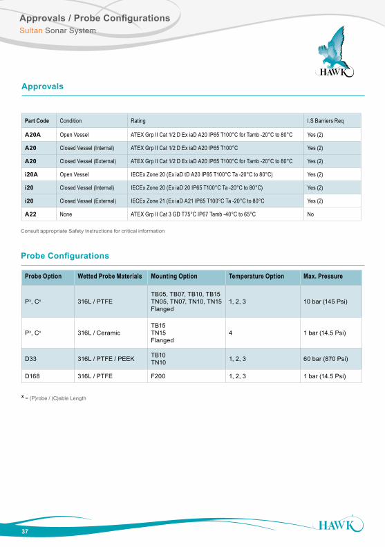
Part Code Condition Rating I.S Barriers Req
A20A Open Vessel ATEX Grp II Cat 1/2 D Ex iaD A20 IP65 T100°C for Tamb -20°C to 80°C Yes (2)
A20 Closed Vessel (Internal) ATEX Grp II Cat 1/2 D Ex iaD A20 IP65 T100°C Yes (2)
A20 Closed Vessel (External) ATEX Grp II Cat 1/2 D Ex iaD A20 IP65 T100°C for Tamb -20°C to 80°C Yes (2)
i20A Open Vessel IECEx Zone 20 (Ex iaD tD A20 IP65 T100°C Ta -20°C to 80°C) Yes (2)
i20 Closed Vessel (Internal) IECEx Zone 20 (Ex iaD 20 IP65 T100°C Ta -20°C to 80°C) Yes (2)
i20 Closed Vessel (External) IECEx Zone 21 (Ex iaD A21 IP65 T100°C Ta -20°C to 80°C Yes (2)
A22 None ATEX Grp II Cat 3 GD T75°C IP67 Tamb -40°C to 65°C No
Approvals
Probe Option Wetted Probe Materials Mounting Option Temperature Option Max. Pressure
Px, Cx 316L / PTFETB05, TB07, TB10, TB15 TN05, TN07, TN10, TN15 Flanged
1, 2, 3 10 bar (145 Psi)
Px, Cx 316L / CeramicTB15 TN15 Flanged
4 1 bar (14.5 Psi)
D33 316L / PTFE / PEEK TB10 TN10 1, 2, 3 60 bar (870 Psi)
D168 316L / PTFE F200 1, 2, 3 1 bar (14.5 Psi)
Probe Configurations
Consult appropriate Safety Instructions for critical information
X = (P)robe / (C)able Length
38
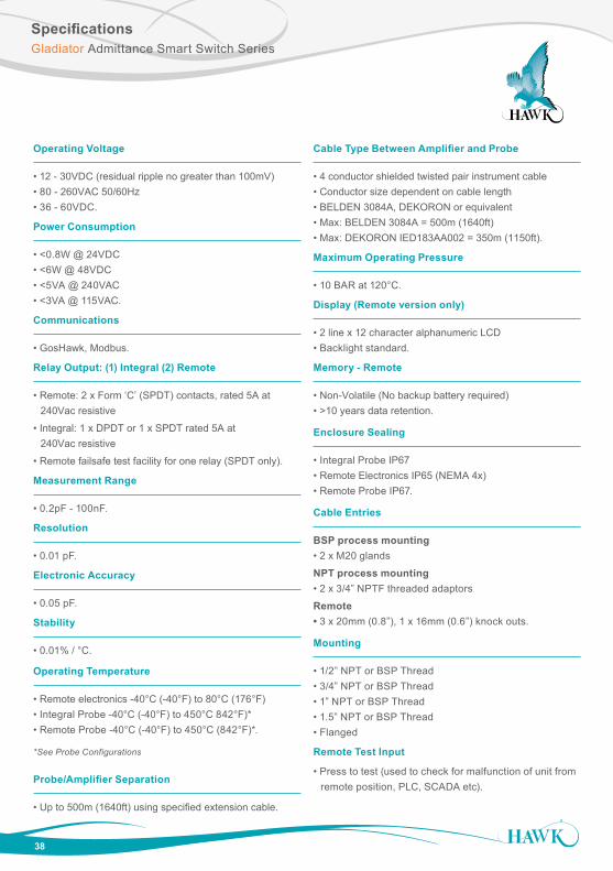
SpecificationsGladiator Admittance Smart Switch Series
Operating Voltage
• 12 - 30VDC (residual ripple no greater than 100mV) • 80 - 260VAC 50/60Hz • 36 - 60VDC.
Power Consumption
• <0.8W @ 24VDC • <6W @ 48VDC • <5VA @ 240VAC • <3VA @ 115VAC.
Communications
• GosHawk, Modbus.
Relay Output: (1) Integral (2) Remote
• Remote: 2 x Form ‘C’ (SPDT) contacts, rated 5A at 240Vac resistive
• Integral: 1 x DPDT or 1 x SPDT rated 5A at 240Vac resistive
• Remote failsafe test facility for one relay (SPDT only).
Measurement Range
• 0.2pF - 100nF.
Resolution
• 0.01 pF.
Electronic Accuracy
• 0.05 pF.
Stability
• 0.01% / °C.
Operating Temperature
• Remote electronics -40°C (-40°F) to 80°C (176°F) • Integral Probe -40°C (-40°F) to 450°C 842°F)* • Remote Probe -40°C (-40°F) to 450°C (842°F)*.
*See Probe Configurations
Probe/Amplifier Separation
• Up to 500m (1640ft) using specified extension cable.
Cable Type Between Amplifier and Probe
• 4 conductor shielded twisted pair instrument cable • Conductor size dependent on cable length • BELDEN 3084A, DEKORON or equivalent • Max: BELDEN 3084A = 500m (1640ft) • Max: DEKORON IED183AA002 = 350m (1150ft).
Maximum Operating Pressure
• 10 BAR at 120°C.
Display (Remote version only)
• 2 line x 12 character alphanumeric LCD • Backlight standard.
Memory - Remote
• Non-Volatile (No backup battery required) • >10 years data retention.
Enclosure Sealing
• Integral Probe IP67 • Remote Electronics IP65 (NEMA 4x) • Remote Probe IP67.
Cable Entries
BSP process mounting • 2 x M20 glands
NPT process mounting • 2 x 3/4” NPTF threaded adaptors
Remote • 3 x 20mm (0.8”), 1 x 16mm (0.6”) knock outs.
Mounting
• 1/2” NPT or BSP Thread • 3/4” NPT or BSP Thread • 1” NPT or BSP Thread • 1.5” NPT or BSP Thread • Flanged
Remote Test Input
• Press to test (used to check for malfunction of unit from remote position, PLC, SCADA etc).
Dielectric Constants TableGladiator Admittance Smart Switch Series
All company or product names are registered trademarks or trademarks of their respective owners.
DO
C-A
DM
ITTA
NC
E-M
AN
Rev
. 1.1
4 0
816
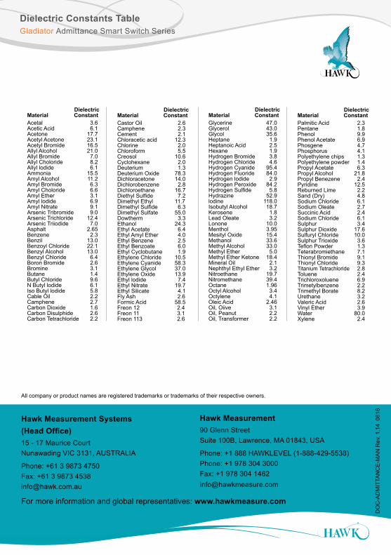
DielectricMaterial ConstantGlycerine 47.0Glycerol 43.0Glycol 35.6Heptane 1.9Heptanoic Acid 2.5Hexane 1.9Hydrogen Bromide 3.8Hydrogen Chloride 4.6Hydrogen Cyanide 95.4Hydrogen Fluoride 84.0Hydrogen lodide 2.9Hydrogen Peroxide 84.2Hydrogen Sulfide 5.8Hydrazine 52.9lodine 118.0Isobutyl Alcohol 18.7Kerosene 1.8Lead Oleate 3.2Lonone 10.0Menthol 3.95Mesityl Oxide 15.4Methanol 33.6Methyl Alcohol 33.0Methyl Ether 5.0Methyl Ether Ketone 18.4Mineral Oil 2.1Nephthyl Ethyl Ether 3.2Nitroethane 19.7Nitromethane 39.4Octane 1.96Octyl Alcohol 3.4Octylene 4.1Oleic Acid 2.46Oil, Oiive 3.1Oil, Peanut 2.2Oil, Transformer 2.2
DielectricMaterial ConstantAcetal 3.6Acetic Acid 6.1Acetone 17.7Acetyl Acetone 23.1Acetyl Bromide 16.5Allyl Alcohol 21.0Allyl Bromide 7.0Allyl Choloride 8.2Allyl lodide 6.1Ammonia 15.5Amyl Alcohol 11.2Amyl Bromide 6.3Amyl Choloride 6.6Amyl Ether 3.1Amyl lodide 6.9Amyl Nitrate 9.1Arsenic Tribromide 9.0Arsenic Trichloride 12.4Arsenic Triiodide 7.0Asphalt 2.65Benzene 2.3Benzil 13.0Benzoyl Chloride 22.1Benzyl Alcohol 13.0Benzyl Chloride 6.4Boron Bromide 2.6Bromine 3.1Butane 1.4Butyl Chloride 9.6N Butyl lodide 6.1Iso Butyl lodide 5.8Cable Oil 2.2Camphene 2.7Carbon Dioxide 1.6Carbon Disulphide 2.6Carbon Tetrachloride 2.2
DielectricMaterial ConstantCastor Oil 2.6Camphene 2.3Cement 2.1Chloracetic acid 12.3Chlorine 2.0Chloroform 5.5Creosol 10.6Cyclohexane 2.0Deuterium 1.3Deuterium Oxide 78.3Dichloracetone 14.0Dichlorobenzene 2.8Dichloroethane 16.7Diethyl Sulfide 7.2Dimethyl Ethyl 11.7Dimethyl Sulfide 6.3Dimethyl Sulfate 55.0Dowtherm 3.3Ethanol 24.3Ethyl Acetate 6.4Ethyl Amyl Ether 4.0Ethyl Benzene 2.5Ethyl Benzoate 6.0Ethyl Cyclobutane 1.9Ethylene Chloride 10.5Ethylene Cyanide 58.3Ethylene Glycol 37.0Ethylene Oxide 13.9Ethyl lodide 7.4Ethyl Nitrate 19.7Ethyl Silicate 4.1Fly Ash 2.6Formic Acid 58.5Freon 12 2.4Freon 11 3.1Freon 113 2.6
DielectricMaterial ConstantPalmitic Acid 2.3Pentane 1.8Phenol 9.9Phenol Acetate 6.9Phosgene 4.7Phosphorus 4.1Polyethylene chips 1.3Polyethylene powder 1.4Propyl Acetate 6.3Propyl Alcohol 21.8Propyl Benezene 2.4Pyridine 12.5Reburned Lime 2.2Sand (Dry) 4.8Sodium Chloride 6.1Sodium Oleate 2.7Succinic Acid 2.4Sodium Chloride 6.1Sulphur 3.4Sulphur Dioxide 17.6Sulfuryl Chloride 10.0Sulphur Trioxide 3.6Teflon Powder 1.3Teterabromiethane 7.1Thionyl Bromide 9.1Thionyl Chloride 9.3Titanium Tetrachloride 2.8Toluene 2.4Trichloroxoluene 6.9Trimetylbenzene 2.2Trimethyl Borate 8.2Urethane 3.2Valeric Acid 2.6Vinyl Ether 3.9Water 80.0Xylene 2.4
For more information and global representatives: www.hawkmeasure.com
Hawk Measurement Systems(Head Office)15 - 17 Maurice Court Nunawading VIC 3131, AUSTRALIA
Phone: +61 3 9873 4750Fax: +61 3 9873 [email protected]
Hawk Measurement 90 Glenn Street Suite 100B, Lawrence, MA 01843, USA
Phone: +1 888 HAWKLEVEL (1-888-429-5538)Phone: +1 978 304 3000Fax: +1 978 304 [email protected]