DYNAMIC STABILITY and WHIRL MOTION of LARGE … · floating bush bearing is the multilobed or...
30
Vibration Institute 34 th Annual Meeting, June 22-26, 2010 Oak Brook, Illinois DYNAMIC STABILITY and WHIRL MOTION of LARGE DIESEL ENGINE TURBOCHARGERS in FLOATING BUSH and MULTI-LOBED BEARINGS Edgar J. Gunter, Ph.D. RODYN Vibration Analysis, Inc. Professor Emeritus Mechanical and Aerospace Engineering Former Director, Rotor Dynamics Laboratory, Univ. Of Virginia Fellow ASME [email protected] Wen Jeng Chen, Ph.D. Eigen Technologies, Inc. Fellow ASME [email protected] Abstract: This paper deals with the stability and nonlinear dynamical analysis of a class of turbocharger used on locomotives and marine diesel engines. These larger sized turbochargers operate at 30,000 RPM and use floating ring bearings. The floating ring bearing is very common for use in the smaller highspeed automotive engines. The use of floating ring bearings for the heavier turbochargers can encounter a number of difficulties which can lead to catastrophic failure of the impeller and shaft, depending upon operating conditions and clearance values of the bearings. All turbochargers mounted in floating ring bearings are inherently unstable with limit cycle whirling. The whirl orbits are controlled by the nonlinear bearing forces generated in the inner and outer fluid films of the bearings. Depending upon the floating ring bearing clearances, a sufficiently high whirl motion can occur, causing the compressor impeller to rub, leading to impeller and shaft failure. A very tight internal compressor bearing ring clearance may cause the bushing to freeze to the shaft. When this occurs the bushing acts as a large clearance journal bearing and is violently unstable. The ensuing large amplitude whirl motion leads to rapid turbocharger failure. Dynamical models are presented to show the nonlinear behavior of the turbocharger and the magnitudes of the limit cycle whirl motion with both the floating bush bearing and various multi-lobed bearing designs. Attempts to make a multilobed bearing out of a floating bush bearing by adding axial grooves is not effective and may actually lead to larger whirl orbits. Improvements in turbocharger reliability with floating bush bearings may be obtained by the use of closely controlled bearing ring clearances, use of a synthetic lubricant, secondary turbocharger oil filtration, turbocharger overspeed controls, and increased radial clearances in the turbocharger inducer and compressor sections. Finally, a superior bearing design is presented using a 3 lobed bearing design which improves the stability characteristics and reduces the nonsynchronous whirl amplitudes. Keywords: Floating bush bearings; limit cycle motion; multi-lobed bearings; nonlinear transient response; rotor stability; self-excited whirling; turbochargers Dyrobes Rotordynamics Software http://dyrobes.com
Transcript of DYNAMIC STABILITY and WHIRL MOTION of LARGE … · floating bush bearing is the multilobed or...

Vibration Institute 34th Annual Meeting, June 22-26, 2010 Oak Brook, Illinois
DYNAMIC STABILITY and WHIRL MOTION of LARGE DIESEL ENGINETURBOCHARGERS in FLOATING BUSH and MULTI-LOBED BEARINGS
Edgar J. Gunter, Ph.D.RODYN Vibration Analysis, Inc.
Professor Emeritus Mechanical and Aerospace EngineeringFormer Director, Rotor Dynamics Laboratory, Univ. Of Virginia
Fellow [email protected]
Wen Jeng Chen, Ph.D.Eigen Technologies, Inc.
Fellow [email protected]
Abstract:
This paper deals with the stability and nonlinear dynamical analysis of a class of turbocharger used onlocomotives and marine diesel engines. These larger sized turbochargers operate at 30,000 RPM and usefloating ring bearings. The floating ring bearing is very common for use in the smaller highspeedautomotive engines. The use of floating ring bearings for the heavier turbochargers can encounter anumber of difficulties which can lead to catastrophic failure of the impeller and shaft, depending uponoperating conditions and clearance values of the bearings. All turbochargers mounted in floating ringbearings are inherently unstable with limit cycle whirling. The whirl orbits are controlled by thenonlinear bearing forces generated in the inner and outer fluid films of the bearings. Depending upon thefloating ring bearing clearances, a sufficiently high whirl motion can occur, causing the compressorimpeller to rub, leading to impeller and shaft failure. A very tight internal compressor bearing ringclearance may cause the bushing to freeze to the shaft. When this occurs the bushing acts as a largeclearance journal bearing and is violently unstable. The ensuing large amplitude whirl motion leads torapid turbocharger failure. Dynamical models are presented to show the nonlinear behavior of theturbocharger and the magnitudes of the limit cycle whirl motion with both the floating bush bearing andvarious multi-lobed bearing designs. Attempts to make a multilobed bearing out of a floating bushbearing by adding axial grooves is not effective and may actually lead to larger whirl orbits.Improvements in turbocharger reliability with floating bush bearings may be obtained by the use ofclosely controlled bearing ring clearances, use of a synthetic lubricant, secondary turbocharger oilfiltration, turbocharger overspeed controls, and increased radial clearances in the turbocharger inducerand compressor sections. Finally, a superior bearing design is presented using a 3 lobed bearing designwhich improves the stability characteristics and reduces the nonsynchronous whirl amplitudes.
Keywords: Floating bush bearings; limit cycle motion; multi-lobed bearings; nonlinear transientresponse; rotor stability; self-excited whirling; turbochargers
Dyrobes Rotordynamics Softwarehttp://dyrobes.com

Introduction:
The turbochargers used for the large stationary and marine diesel engines are considerablylarger than the typical turbochargers used in automotive engines. The diesel engineturbocharger under consideration is shown in Figure 1.
These turbochargers operate at a speed ofapproximately 30,000 RPM, as compared toover 100,000 RPM for the automotiveturbochargers. The typical turbochargerdesign is a double overhung turbo-rotor witha steel turbine wheel of high temperaturealloy and an attached aluminum compressorwheel. The typical type of bearings used forthe smaller high-speed automotiveturbochargers is the floating ring bearing.The concept of the floating ring bearing wasdeveloped in the 1930s. The original concept
was to reduce horsepower losses. A plain journal bearing, for example, will not operatesatisfactorily in either the smaller turbochargers operating at 100,000 RPM or the much largerdiesel engine turbochargers with an operational speed of only 30,000 RPM. The reason forthis is due to the inherent self-excited whirl instability encountered with a fixed plain journalbearing. At higher speeds, the rotor will go into a subsynchronous whirl motion. Continuedoperation with a plain journal bearing at high speed will result in excessive bearing wearfollowed by total rotor failure.
With the floating ring bearing, for example, as shown in Figure 12, the journal bearing is notfixed but is a ring which is free to float on the shaft. The ring rotates at a fraction of the shaftrunning speed from a theoretical maximum of 50% to as low as 15% of running speed. Thering speed is controlled by the viscosity of the inner and outer oil films and the clearances ofthe inner and outer bearings. The inner ring clearance of the ring is kept at a much tighterclearance than the outer ring. This causes more friction losses in the inner clearance, resultingin higher temperatures and lower oil viscosity.
Although the floating ring bearing itself is unstable from a linearized standpoint, the rotormotion will form a limit cycle whirl motion due to the nonlinear bearing forces. This isreferred to as subsynchronous whirling with double overhung turbochargers. The turbochargerwill precess at a fraction of running speed. Normally, the whirl motion encountered is aconical whirling motion. Under properly designed clearance ratios for the floating ringbearing, the small turbochargers may run at high speed with controlled limit cycle whirling.
Although the concept of the floating ring bearing is quite simple, the analysis of the dynamicalbehavior of a turbocharger in a floating ring is exceedingly difficult. This is due to thenonlinear nature of the fluid film and the requirement of the numerical integration of theequations of motion. The advantage of the floating ring bearing is in its simplicity and costof manufacture. Although the floating ring bearing is simple to manufacture and is low in cost,it is not recommended for the larger diesel engine turbochargers. A bearing superior to thefloating bush bearing is the multilobed or specifically the 3 lobed bearing. This bearing ismore expensive to manufacture but due to the initial cost of these larger turbochargers, theextra cost is warranted. It will be seen that the 3 lobed bearing has greater stability.
Fig. 1 Diesel Engine Turbocharger
2

Description of Diesel Engine Turbocharger:
The left section as shown in Fig. 1 represents the steel turbine wheel. To the right is attachedthe aluminum compressor wheel with the inducer section. The inducer section is separate fromthe compressor wheel. Typical turbochargers are double overhung rotors. That is, the bearingsare inboard of the turbocharger compressor and turbine wheels. The left bearing represents theturbine-end bearing, and the right end is the compressor-end bearing. Adjacent to thecompressor bearing is the thrust bearing. It should be noted that the turbine-end bearing islarger than the compressor-end bearing. The reason for this is for ease of assembly anddisassembly for field maintenance.
Figure 2 represents a cutaway of the diesel-engine turbocharger. This figure is of interest as itshows the construction and method of attachment of the compressor and inducer wheels. Thesteel shaft extends under the compressor and inducer wheels. The compressor wheels areattached to the wheel shaft by means of a sleeve and bolt arrangement. There is an end cap, orbell, which maintains the compressor and inducer wheels. In Figure 1, the compressor wheelassembly appears to be fairly rigidly attached to the shaft. In reality, because of the extensionof the steel shaft and the sleeve, the overhang of the compressor section is fairly flexible.
Design Considerations for the Turbocharger:
The principle design consideration for the turbocharger is primarily with the aerodynamicperformance of the compressor wheel and the design of the turbine for the power required to
drive the compressor. Theaerodynamics of the compressor designare indeed quite elaborate, as thecompressor design is quitesophisticated in order to meet the headrequirements for the system. Theturbocharger compressor wheel isalways an open-bladed radialcentrifugal compressor design with abackward sweep. The backward sweepof the blades is to generate a largerQ/N flow region. In order not to starvethe inlet of the compressor wheel, there
are 10 splitter vanes in addition to the 10 larger impeller vanes.
Small auto engine turbochargers operate at speeds exceeding 100,000 RPM. The design speedof this particular type of the turbocharger is 30,000 RPM. The primary consideration for thesmaller turbochargers is cost, as the smaller ones may cost only several hundred dollars. Theselarger turbochargers may exceed $70,000 in cost. The cost of repair and replacement of theseturbochargers therefore can represent a considerable outlay of funds. The second major designconsideration for the turbocharger is the centrifugal stresses in the turbine, and particularly thecompressor wheel. These compressors are designed such that they are well below the burstspeed. A third major consideration for the design of the turbocharger is ease of assembly anddisassembly. The steel alloy turbine wheel is usually friction welded to the steel shaft. Thealuminum impeller wheels are attached to the shaft, as previously mentioned, by the sleeve.
Fig 2 Turbocharger Cross Section
3

Since the compressor wheel is assembled and bolted on to the steel shaft, this results in acompressor bearing design which is smaller than the turbine bearing.
Compressor and inducer wheel clearances as such are required to be close to line to line contact.At the operating speed of 30,000 RPM, the centrifugal expansion of the compressor wheelassembly, therefore, does not provide a great deal of stiffening to the steel shaft and theextension sleeve. The major stiffness of the assembly is controlled by the steel shaft supportingthe compressor wheel and inducer.
The final consideration for the design of these high-speed turbochargers is the bearing type tobe employed with the turbocharger. With the smaller turbochargers, the floating ring bearingis commonly used. With the smaller automobile type turbochargers, where cost is a greatconsideration, the floating bush bearing has found to be satisfactory provided that properclearances of the inner and outer ring are maintained. This type of bearing is also currentlybeing used in this particular class of turbocharger.
The problem with the floating ring bushing design is that at high speeds, the turbocharger isinherently unstable. That is, the turbocharger exhibits self-excited whirl motion in which theturbocharger is precessing or whirling at a lower frequency. This is referred to asnonsynchronous precession. The predominate whirl mode is usually a conical motion of therotor. By properly controlling the ring inner and outer clearances , a bounded finite limit cycleorbit or motion can be obtained. In order to keep this limit cycle motion within bounds, theinner clearance must be very tight, leading to high bearing temperatures and other operatingproblems associated with tight bearing clearances.
The floating bush bearing operates by spinning at a fraction of the rotor speed. The typicalprecession rate of the ring speed may be from 15-30% of shaft speed. The outer ring clearanceis normally several times larger then the clearance of the outer ring. Theoretical ring speed cango as high as 50%, although this is never achieved in practice. The maximum ring speed islimited by the higher temperatures generated in the inner ring. By properly controlling the ringinner and outer clearances, a bounded finite limit cycle orbit or motion can be obtained. The mechanism of the outer ring acts as a type of crude squeeze-film damper to generatenonlinear forces to cause a limit cycle whirl motion. This bearing type, which is well suited forthe smaller turbochargers because of cost consideration, is not an ideal bearing for the larger,more expensive turbochargers. The larger turbochargers, which weigh approximately 44 lbs,may operate with large limit cycle motions, even with properly controlled clearances. Inaddition to the self-excited whirl motion inherent in the floating bushings themselves, there areadditional aerodynamic forces that creates self-excited whirl motion in all compressors andturbines. This effect is referred to as the Alford effect. The Alford effect causes cross-coupledaerodynamics bearing forces to act on the compressor and turbine, which also promotesinstability.
It will also be shown that the compressor bearing should be larger than the turbine bearing,since this bearing carries the higher bearing loads. The smaller compressor bearings aredesigned from the standpoint of the ease of assembly and disassembly. It will be seen thatdamage and failure are predominantly associated with the compressor-end bearings.Unfortunately, with most turbochargers, whether they be small or large, the bearing design isan approximation based on previous practice and experience. The engineering, until recently,has been limited because of the lack of rotor dynamics codes to compute the nonlinear fluid-film bearing forces and also the nonlinear time transient motion of the turbocharger.
4

These bearings usually are designed and perfected primarily based on experimental testing.Since the large diesel engine turbochargers cost an order of magnitude greater than the smallerautomotive turbochargers, one can afford to design a more effective bearing system for theturbochargers, such as the multi-lobed bearing. The theory of these multi-lobed bearings is wellestablished and has also been employed in other large diesel engine turbochargers.
It is now possible to combine the nonlinear fluid-film characteristics of either the floating-ringor the multi-lobed bearing with a nonlinear time transient analysis of the complete turbochargerto generate the magnitude of the limit cycle motion and bearing forces transmitted. At the timethis class of turbocharger was designed, this type of technology was not generally available forcommercial use.
Critical Speed Analysis:
Although the bearings for the turbocharger are highly nonlinear, it is of considerable value toperform a critical speed analysis of the turbocharger. By means of a critical speed analysis, onecan determine the relative mode shapes and the energy distribution in each bearing and shaft forthat particular mode.
Figure 3 represents a computer model of the turbocharger used for the critical speed analysis.The model contains 48 degrees-of-freedom and represents three levels of attachment. It shouldbe noted that a computation of a built up rotor or multi-level rotor construction is difficult toperform using the transfer matrix method.
Station 2 represents the turbine section. The turbine bearing is located at station 3 and thecompressor bearing is located at station 7. The compressor and inducer sections are attachedto a steel shaft which is in turn held to the main shaft by means of a bolt attachment. Thecircular dot near station 5 represents the center of gravity of the entire assembly.
Fig 3 Critical Speed Model
5
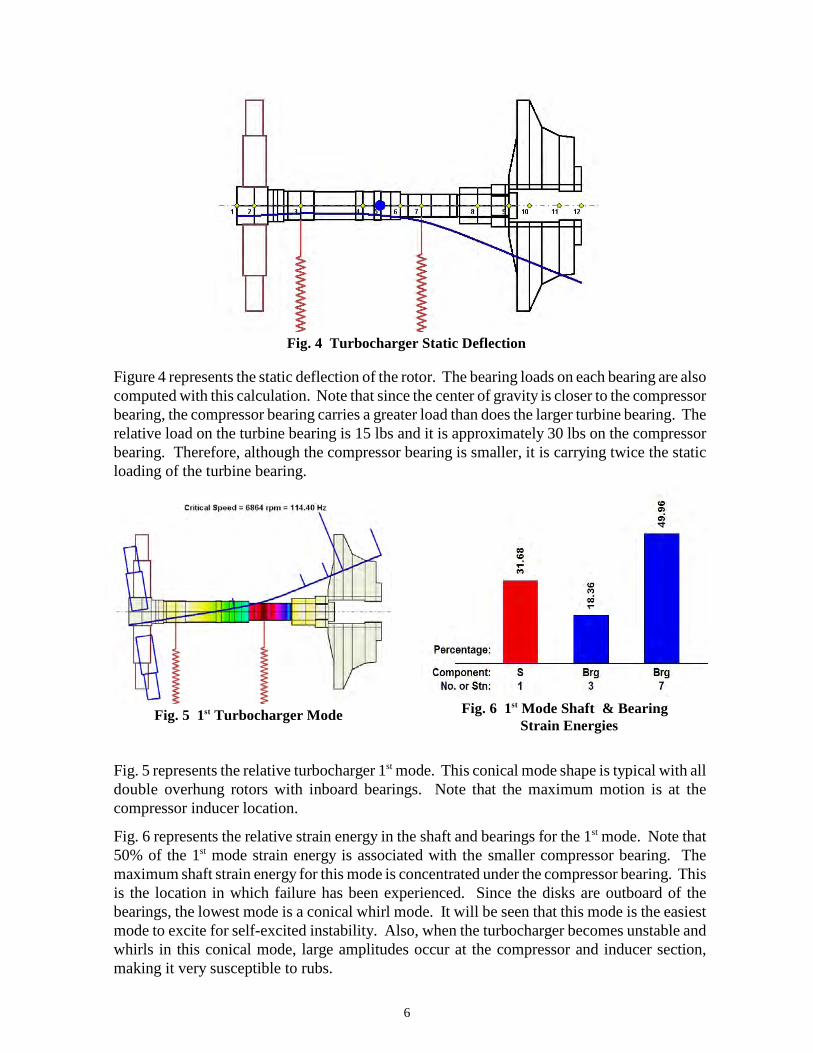
Figure 4 represents the static deflection of the rotor. The bearing loads on each bearing are alsocomputed with this calculation. Note that since the center of gravity is closer to the compressorbearing, the compressor bearing carries a greater load than does the larger turbine bearing. Therelative load on the turbine bearing is 15 lbs and it is approximately 30 lbs on the compressorbearing. Therefore, although the compressor bearing is smaller, it is carrying twice the staticloading of the turbine bearing.
Fig. 5 represents the relative turbocharger 1 mode. This conical mode shape is typical with allst
double overhung rotors with inboard bearings. Note that the maximum motion is at thecompressor inducer location.
Fig. 6 represents the relative strain energy in the shaft and bearings for the 1 mode. Note thatst
50% of the 1 mode strain energy is associated with the smaller compressor bearing. Thest
maximum shaft strain energy for this mode is concentrated under the compressor bearing. Thisis the location in which failure has been experienced. Since the disks are outboard of thebearings, the lowest mode is a conical whirl mode. It will be seen that this mode is the easiestmode to excite for self-excited instability. Also, when the turbocharger becomes unstable andwhirls in this conical mode, large amplitudes occur at the compressor and inducer section,making it very susceptible to rubs.
Fig. 4 Turbocharger Static Deflection
Fig. 5 1 Turbocharger Modest Fig. 6 1 Mode Shaft & Bearingst
Strain Energies
6

Figure 7 represents the second mode of the turbocharger. In this mode, the turbine andcompressor are in phase. There is more bending strain energy in the shaft. The turbochargermay exhibit instability in the second mode, as well as the first. However, the higher, orcylindrical mode, is normally not as sensitive to unbalance or self-excited motion as the conicallower mode is. Figure 7 represents the strain energy distribution for the second mode. In thismode it is seen that there is a much higher strain energy distribution in the turbine-end bearing.The compressor end bearing has little influence on controlling this mode.
Fig. 9 represents the turbocharger 3 mode. Under normal conditions, this mode should berd
above the operating speed with well designed bearings. This mode is shown to be at a speedof 54,000 RPM with the assumed linear bearings. With a loose connection of the compressorattachment section to the main shaft , this higher bending critical speed may be greatly reduced.
Fig. 10 represents the 4 backward mode at 33,724 RPM. If the turbocharger should over speedth
and rub, then this mode could be excited causing a violent backward precession of thecompressor wheel. Hence, any instances of rubbing on the inducer or compressor at operatingspeed could lead to the initiation of a violent sustained backward whirling causing failure.
Fig. 8 2 Mode Relative Shaftnd
& Bearing Strain EnergiesFig. 7 2nd Turbocharger Mode
Fig. 10 Backward Mode at 33,700 RPMFig. 9 Turbo 3 Mode at 54,000 RPMrd
7

Modeling of Turbocharger in Floating Bush Bearings:
The diesel engine turbocharger, including the floating bush fluid-film bearings, was modeledusing the DyRoBeS rotor-bearing dynamics software. Figure 11 represents a cross-section ofthe turbocharger as modeled using the DyRoBeS software to include the floating bushbearings. The rotor is modeled with 11 finite element shaft elements which include 30 sub-elements. The rotor is actually modeled as a 3-bearing system. The bearings 1 and 2, atstations 3 and 7, represent the floating bush bearings.
The bearing station at station 10 is used tointroduce the Alford type of aerodynamiccross-coupling forces acting on thecompressor wheel. The complete system isrepresented by a total of 52 degrees-of-freedom for displacements and rotations.Note that the center of gravity of the turbois closer to the compressor bearing. Thiscauses the compressor bearing loads to bedouble the turbine bearing. Also shown onFigure 11 is a red arrow at station 10. Thisrepresents an applied unbalance. Inaddition to external forcing functions suchas unbalance, one could also add shaft bowand disk skew as exciting forces. From alinearized stability standpoint the systemwould be characterized by 104 complexeigenvalues. Of these eigenvalues, onlythe lower modes are of interest.
Floating Bush Bearings:
A schematic of the floating bush bearings is shown in Fig. 12. The location of the floatingbush bearings are at stations 13 and 14 as shown in Fig. 11. The masses of the rings are actingat stations 13 and 14.
In order to perform a time transientanalysis, the equations of motion areintegrated forward in time. It isrequired, therefore, to integrate 52second order equations simultaneouslywhile computing the nonlinear bearingfluid-film forces at each time increment.Some care has to be exhibited ingenerating the model in order toexpedite the numerical time transientcalculations and to ensure convergenceof the solution. The numericalnonlinear time transient solution will bediscussed in detail in a later section.
Fig. 11 DYROBES Turbo Model Including Floating Bush Bearings
Fig. 12 Schematic of Floating Bush Bearing
8

With this model, in addition to the time transient response, one may calculate the nonlinearsynchronous unbalance response of the turbocharger system due to assumed values ofunbalance acting on the compressor or turbine. In addition to the response caused by radialunbalance, the influence of shaft bow or disk skew may also be included.
It is apparent from looking at the critical speed mode shapes and energy distribution that theconical whirl mode is of greatest concern. The larger turbine bearing will have little influenceon controlling this mode as the predominant strain energy is in the compressor bearing.Although the turbine bearing has a reduced strain energy as compared to the compressorbearing, paradoxically an increase in the turbine floating ring clearances will cause excessiveconical motion leading to turbocharger failure. Therefore, we shall see later that the clearancespecifications of the turbine floating bush bearing cannot be ignored.
Floating Bush Bearing Coefficients:
Although the behavior of the floating bush bearings are highly nonlinear, it is desirable todetermine the linearized bearing coefficients in order to perform a complex damped eigenvalueanalysis on the system. This is usually referred to as a stability analysis. The critical speedanalysis is an undamped analysis which assumed circular synchronous precession. In thisanalysis, only one nominal bearing coefficient is assumed. In order to perform a stabilityanalysis, the computation of 8 bearing coefficients are required for both the inner and outersurfaces of the floating bush bearing.
Table 1 represents some typical dimensions of the turbocharger floating bush bearings. It isseen that the turbine bearing is larger than the compressor bearing even though it is carryinga much lower load. Using these dimensions the bearing stiffness and damping coefficientsmay be computed for each bearing. These dimensions are used for the computation of thebearing coefficients for each ring.
Table 1 - Floating Bush Bearing Characteristics
s i d b o odD L C D L C W
Compressor 1.32 1.0 .001 1.80 1.0 .005 33
Turbine 1.70 1.0 .002 2.165 1.0 .005 11
In Table 1 is shown the inner and outer clearances of the compressor and turbine end bushingbearings. Note that the specified diametral internal clearance of the compressor bushing is 1mil. This is about one-third the thickness of a human hair. With this tight a clearance, thecompressor bearing must be well supplied with oil as it will run hot. The outer ring clearancesare 5 mils. The outer ring clearances are normally specified as larger then the inner ringclearances. The specified ranges of clearances permitted for both bearings is rather large. Forexample, the turbine bearing clearance is specified to be as large as 3.2 mils for the innerclearance and 10.5 mils for the outer ring clearance. It will be seen that these large values ofspecified permissible clearances is excessive and will lead to turbocharger failure.
9

Figure 13 represents the bearing pressure profile and stiffness and damping coefficients for thecompressor end bearing. The inner and outer surfaces of the ring develop a very similarpressure profile except that the bearing coefficients generated from each pressure field areconsiderably different.
There are two assumptions that were made in the calculation of the floating bush bearingcoefficients. The ring speed was computed to be around 0.3 and the oil viscosity of the innerring is always assumed to be lower that the outer ring viscosity.
Tables 2 and 3 represent the bearing coefficients for the compressor and turbine bearings
Table 2
Compressor Bush Bearing Coefficients - 30,000 RPM
XX XY YX YY XX XY YX YYK K K K C C C C
Inner .733E6 10.4E6 -14.1E6 .52E6 5100 -326 -326 6920
Outer 30,000 58,000 -81,200 18,600 128 -31 -31 128
In Tables 2 and 3, it is seen that the inner oil film stiffnesses are an order of magnitude higherthen the bearing coefficients generated by the outer film. Note also that the inner ring bearingstiffness cross coupling coefficients are an order of magnitude greater than the direct bearingstiffness coefficients. The high cross coupling stiffness coefficients are the principle sourceof the cause of self excited nonsynchronous whirl motion.
TABLE 3
Turbine Bush Bearing Coefficients - 30,000 RPM
XX XY YX YY XX XY YX YYK K K K C C C C
Inner .63E6 15.0E6 -19.4E6 .57E6 7360 -300 -300 9500
Outer 11,100 69,000 -87,000 4810 150 -13 -13 184
Fig. 13 Compressor Floating Bush BearingCoefficients at 30,000 RPM
10

Stability of Turbocharger in Floating Ring Bearings:
Using the floating bush bearing coefficients, based on nominal clearances, as shown in Tables2 and 3, a damped eigenvalue analyses may be performed to determine the relative stability ofthe turbocharger at the assumed operating speed of 30,000 RPM. By varying the turbine andcompressor ring clearances, it may be determined which clearance values produce improvedstability characteristics. In addition to the bearing coefficients, an additional aerodynamic cross-coupling excitation of 500 lb/in was assumed acting at the compressor location.
Based on the bearing characteristics, as shown in Table 2 and 3, the damped eigenvalues for theturbocharger were computed. Figure 14 represents the first forward mode of the turbocharger,and it is a conical motion with the maximum amplitude at the compressor. With the dimensionsas specified in Table 1, the first conical mode is stable with a whirl frequency of 4814 CPM anda log decrement of 0.31.
In order to achieve this predicted stable motion based on linearized bearing coefficients, theinner ring clearance of the compressor bearing is a tight 1 mil clearance and the turbinediametral clearance is 2 mils. The outer ring clearance for both bearings is 5 mils. The conicalmode shape is essentially a rigid body mode with the largest amplitude at the compressor andinducer location. The indicated subsynchronous whirl frequency is 4814 CPM.
The 1 conical mode is stable with the coefficients as listed in Tables 2 & 3. If, however, thest
turbine bearing ring clearances are increased from the nominal values of 2 mils for the innerclearance and 5 mils for the outer ring clearance to the stated maximum values of 3.2 milsinternal and 10.5 mils external, then we have an unstable situation as shown in Fig. 15.
The increase in turbine bearing clearances causes an unstable whirling situation. Strict limitson the turbine bearing must be maintained to minimize self excited instability to occur. Hencea sloppy turbine bushing bearing is an invitation to turbocharger failure, even though no failureof the turbine bearing itself is ever experienced. Therefore, it appears that the maximum turbinebearing clearance values as specified by the manufacturer are not permissible, as this wouldinduce turbocharger instability in the first conical mode.
Fig. 14 Stable 1 Mode With Nominal Brg Clearancesst
Nf1 = 4814 CPM , Log Decrement * = .31
11

Although the turbine bearing never experiences failure, it is imperative that this bearingclearance be kept tight in order to maintain proper stability. Instability in the higher cylindricalmode is also encountered with excessive turbine bearing clearances.
Whirl Mode Near Running Speed:
On the marine diesel engines, there are no speed controls on the turbochargers. This is a concernwhen the turbocharger is operated over 30,000 RPM. Figure 16 represents the eightheigenvalue, which is the third forward critical speed. Note that this mode is at 33,000 RPM,which is 10% over design speed. There is a concern that if the turbocharger is over-sped, thatthis mode could be excited, leading to possible compressor rubs.
In this mode, it is seen that the maximum amplitude occurs at the compressor location.
Fig. 15 Unstable 1 Mode With Maximum Turbine Bearing st
Clearances, Nf1 = 4121CPM , * = - 0.64
Fig 16. Turbocharger Bending Mode Above Running Speed at 33,500 RPM
12

Locked Compressor Bearing Leading to Failure:
Under marginal lubrication conditions and tight compressor bearing inner clearances, the
compressor bearing may weld onto the shaft. When this occurs, the floating bush bearing
essentially becomes a plain bearing with a large clearance. The result of a locked bearing
causes a very strong subsynchronous conical whirling to occur with large motion at the
compressor. This frequency is predicted to be about 7,500 RPM. To compound the
problem, the third forward critical speed drops down further into the operating speed
range. Thus, the frozen, or locked, compressor bushing bearing leads to immediate
turbocharger failure, usually resulting in shearing of the shaft under the compressor
bearing as shown in Figure 17.
Figure 17 shows the effect of a rub on
the compressor wheel. The blades are
stripped, and the compressor has sheared
the shaft under the compressor bearing.
Once the inducer section or compressor
wheel initiates a rub on the volute, the
gyroscopic moments of the wheel
reverse moment direction and tend to
cause the wheel to precess backwards in
the casing. This leads to rapid and
extensive damage that is difficult to
catch in time to avoid a total
catastrophic compressor, inducer and
shaft failure.
When the floating ring seizes to the
shaft, the bearing becomes a plain journal bearing. The stability characteristics of the
plain journal bearing are quite poor and prone to self excited whirl instability at lower
speeds dependant upon the bearing clearance. In fact a remarkable approximate equation
to estimate the stability of a plain journal bearing is given as follows:
(1)
For the case of the locked compressor ring bearing with a diametral clearance of 5 mils,
the estimated stability threshold for the plain bearing, neglecting flexible shaft effects is
predicted to be:
(2)
The above equation is an approximation of the threshold of stability for the plain journal
bearing with a diametral clearance of 5 mils. This speed is less than one third of the
operating speed of the turbocharger. Thus the floating ring compressor bearing welded
Fig.17 Failed Compressor and Shaft After Heavy Rub
13

to the shaft may be expected to be highly unstable. To illustrate in more detail the
stability characteristics with a locked compressor ring bearing, the actual bearing
coefficients have been computed using the outer ring clearance and diameter as bearing
parameters. Figure 18 represents the bearing coefficients generated at 30,000 RPM with
the 5 mil clearance and 30 lb radial loading.
The bearing is operating at a low
eccentricity ratio and very high attitude
angle. This implies that the bearing
stiffness cross coupling coefficients will
greatly exceed the principal stiffness
values.
For example, Figure 18 shows that the
direct stiffness value Kxx is 23,300 Lb/In
while the cross coupling coefficient Kyx
is -232,000 Lb/In. This value is an order
of magnitude higher than the direct
stiffness values. This implies that the
turbocharger operating at 30,000 RPM with a compressor ring bearing frozen to the shaft
will be highly unstable.
In order to determine the degree of instability and the resulting turbocharger mode shape,
a stability analysis was performed using the bearing coefficients as shown in Fig. 18.
Figure 19 represents the first conical mode of the turbocharger with the seized
compressor bearing. This highly unstable mode has a predicted whirl frequency of 7,500
CPM and a negative log decrement of -2.1.
Fig. 18 Locked Compressor Bearing Characteristics at 30,000 RPM
Fig. 19 Unstable Conical Whirl Mode at 7500 CPM With Seized Compressor Ring Bearing, Log Dec * = -2.1
14

The seized compressor ring bearing also causes a second higher in-phase unstable cylindricalmode to occur. This mode has a high negative log decrement of -2.55 and a whirl frequency of10,500 CPM. Thus it is possible for the turbocharger to exhibit two unstable modes. An FFTanalysis of the rotor motion may show that both modes may be present. It is of interest to notethat the simplified stability criterion for the plain bearing predicts the rigid body stability to beat 9,200 RPM. The finite element flexible rotor analysis predicts two unstable modes to occurwith frequencies at 7,500 CPM and 10,500 CPM while operating at 30,000 RPM. In the pastit appears that all recorded vibration data had been filtered to remove frequencies below 450 Hz.Therefore, subsynchronous vibrations on this class of turbochargers has not been properlydocumented or observed. Therefore failure can occur without adequate warning.
Nonlinear Time Transient Motion With Floating Ring Bearings:
In order to determine the dynamical motion of the turbocharger in the nonlinear floating
bush bearings, a nonlinear time transient numerical analysis must be performed. Figure
21 represents the transient motion of the rotor for 50 cycles of shaft motion. The
turbocharger is modeled by 14 major mass stations each with 4 degrees of freedom. The
masses of the floating bush bearings represent another 4 degrees of freedom.
Thus for each time step, it is required to integrate 60 equations of motion and solve the
finite element fluid film bearing equations for the forces generated on the inner and
outer ring surfaces of the two floating bush bearings. In order to maintain accuracy of
the orbits, 2000 time steps were used for each cycle of shaft motion.
The numerical computations were performed using the Runge-Kutta procedure as a
starting solution. After several cycles of shaft motion, the solver is switched to the
Newmark-Beta method which is faster but is not a self starter with zero initial
conditions. In addition to the gravitational loads, an aerodynamic cross coupling force
of 500 Lb/In is assumed to be acting at the compressor. Also in the model is a radial
unbalance of 0.2 oz-in acting on the compressor wheel.
Fig. 20 Unstable Cylindrical Whirl Mode at 10500 CPM With Seized Compressor Ring Bearing, * = -2.55
15

Figure 21 represents the nonlinear turbocharger transient motion for 50 cycles of shaft
motion. The orbital motion clearly shows subsynchronous whirling to be present in the
system with the tight clearance floating ring turbine bearing and nominal clearance
compressor ring bearing. For the case of assumed linearized bearing coefficients the
transient whirl orbits would become unbounded. The orbital motion shown with the
nonsynchronous whirl motion is bounded due to the nonlinear effects of the bearings.
The nonsynchronous whirl motion greatly exceeds the synchronous response caused by
the unbalance of 0.2 oz-in acting at the compressor wheel.
Figure 22 represents the motion of the compressor bushing in the housing. Notice that
the whirl orbit fills up over 80 % of the bearing clearance.
Fig. 21 Time Transient Motion of Turbocharger with Tight Turbine Brg, Q=500 Lb/In & 0.2 Oz-In Unbalance
Fig. 22 Bushing Motion, MilsFig. 23 Motion At Compressor Brg ( Inches)
16

On Figure 22 are placed timing marks to represent each shaft revolution. The motion
initially starts off with a small component of synchronous precession and then becomes
dominated by the subsynchronous whirl motion. The scale on Figure 22 is in mils. The
compressor bushing is orbiting with over 5 mils of motion. This large motion will cause
much higher bearing forces to be transmitted than if one had only synchronous
precession caused by the 0.2 oz-in of unbalance. The specified unbalance of 0.2 oz-in
causes a rotating load of about 320 lb at 30,000 RPM. This level of unbalance is
equivalent to the mass center of the compressor to be displaced from the axis of rotation
by approximately 1 mil.
Figure 23 is the absolute motion of the shaft at the compressor bearing location. The
resulting bounded limit cycle orbit is a combination of synchronous precession due to
unbalance and the lower frequency subsynchronous whirl motion. Note the size of the
compressor inner ring clearance as compared to the total orbit observed at the
compressor bearing.
Figure 24 represents the FFT analysis of the motion of the compressor bearing station
as shown in Figure 16. It is seen that the motion is composed of synchronous precession
caused by the rotor unbalance and the lower self-excited whirl motion that is inherent
with the floating bush bearings. If one filters the frequency data below 500 Hz, as is
common practice, then it is apparent that the
important whirling motion will not be observed! It is
seen that the whirl motion is 3 mils of amplitude as
compared to the 2 mils of synchronous motion
created by the rotating unbalance load. One may
surmise that if the bearing were perfectly stable, then
the total amplitude of motion should be reduced by 3
mils. Figure 25 represents the motion of the
compressor inducer. Drawn on this figure is the
inducer clearance circle of the stator vanes. Rubbing
will occur when this orbit exceeds the operating
clearance causing blade contact.
Fig. 24 FFT of Absolute Compressor Bearing Motion
Showing Subsynchronous Whirling
Fig. 25 Inducer Motion, Mils
17

Compressor Floating Ring Bearing Forces Transmitted:
Figure 26 shows the large bearing forces of over +-430 Lb with the 0.2 oz-in of
unbalance. These large transmitted compressor bearing forces are not due to unbalance
alone. Figure 27 shows the compressor floating ring bearing forces for a balanced
rotor. With a perfectly stable rotor system, there should be no dynamic loads after the
initial transient vibration dies out after the first few cycles of shaft motion.
Figure 27 shows dynamic loads being transmitted with forces as high as 370 Lb. This
transmitted loading for the case of a balanced rotor represents a loading which exceeds
the bearing static loading by over a factor of 10. These high dynamic forces are
generated by the large amplitude whirling motion that is inherent in all floating ring
bearings. It is apparent that in order to achieve limit cycle motion, that high bearing
forces must be generated. These high bearing loads may eventually lead to overheating
of the bearing and tar and varnish formation on the inner surface of the compressor
floating ring bearing. Such operating conditions lead to reduced bearing life.
Motion with Large Clearance Turbine and Compressor Bearings:
There is a range of allowableclearances specified for both thecompressor and turbine floating bushbearings. The maximum specifiedvalues for the floating bush turbinebearing is approximately 3 mils for theinner clearance and 10 mils for theouter clearance.
Figure 28 represents the nonlineartransient motion for 50 cycles of shaftmotion with larger clearances on theturbine floating ring bearing. Thelarger turbine ring clearances leads to apronounced conical whirling motionwith high amplitudes at the compressorand inducer sections.
Fig. 27 Compressor Bearing Forces With Balanced Rotor
Fig. 26 Compressor Brg Forces With 0.2 Oz-In Unbalance
Fig. 28 Transient Motion With Large Clearance Turbine Bearing
18

Figure 29 represents the turbine bushing motion with the large inner and outer bushingclearances. The initial transient motion starts out in a controlled limit cycle motioninfluenced by the rotating unbalance forces acting on the compressor wheel. The motion thenchanges into a large limit cycle motion with a conical motion as shown in Figure 28.
Figure 30 shows the resulting motion at the compressor inducer section. This large motionwill lead to rubbing on the inducer section of the compressor wheel which will initiate failure.
Figure 31 represents the compressor bearing forces transmitted with the large prescribedturbine bearing clearances. The initial transient motion starts out with a small controlled limitcycle motion caused by the applied unbalance at the compressor wheel. After about 22 cyclesof shaft motion, the motion of the system jumps into a large conical whirling mode with arapid increase in the bearing forces transmitted. Compressor bearing forces increase to over400 lb.
Fig. 29 Turbine Bushing Motion With Large Clearances, Mils
Fig. 30 Excessive Inducer Motion Caused By Large Turbine Brg Cl
Fig. 31 Compressor Bearing Forces Transmitted With Large Clearance Floating Bush Turbine Bearing
19

Figure 32 represents the turbochargermotion with nominal turbine clearances of2 mils for the inner ring and 6 mils for theouter ring. The compressor bearing hasincreased ring clearances from 1 to 2 milson the inner ring and from 5 to 10 mils forthe outer ring clearance. Added to thedynamical analysis is 0.2 oz-in ofunbalance on the compressor wheel. Thecircle shown on the figure represents theclearance margin between the inducersection of the compressor and thestationary stator vanes.
Note that the orbital path is offset from theclearance circle. This is due to thegravitational loading on the compressor.The motion is clearly in subsynchronouswhirling. The repeated internal loops arecaused by the rotating unbalance load. The motion is clearly in a well defined limit cyclewhirl which is not in contact with the stator. It is apparent that the size of the limit cyclemotion at the compressor and inducer location is strongly influenced by the turbine ringbearing clearances. The turbine ring clearances must be closely controlled in order not tohave excessively large compressor-inducer whirling.
Figure 33 represents the welded steel shaft and turbine assembly after a hard rub.Examination the shaft failure indicates a torsional failure. This failure occurs under thecompressor bearing.
Fig. 32 Motion at Inducer With Large Compressor Ring Bearing Clearances
Figure 33 Steel Turbine Shaft After Hard Compressor - Inducer Rub
20

Stability With Axial Groove Floating Bush Bearings:
Figure 34 represents a floating bush bearing inwhich 3 axial grooves have been added to theinner ring of the bearing and 4 grooves havebeen placed into the stationary bearinghousing. This creates a 4 axial groove bearingfor the outer ring.
The concept for the use of the axial grooves istwo-fold. The first objective is to improve thelubricant supply to the inner and outer bearingsurfaces. The second objective is an apparentattempt to improve the stability characteristicsover a plain journal bearing.
The apparent attempt to promote stability andimproved lubrication of the floating ringbearings by the use of axial grooves is noteffective.
Figure 35 represents the pressure distribution for the inner ring with 3 axial grooves.Figure 35 shows the pressure distribution and stiffness and damping coefficients for thecompressor bearing as shown in Figure 34 for a static loading of 30 lb and minimumspecified diametral of .8 mils. Note that with the load vector directed towards the bottomarc, the other two arcs have not generated a pressure profile. The corresponding bearingcoefficients are shown in Table 4 for the inner ring. These bearing coefficients are reducedas compared to the coefficients as shown in Table 2.
Figure 36 represents the outer ring bearing which has 4 axial grooves in the stationaryhousing. The coefficients for the outer ring are shown in Table 4. These bearing values arereduced from those presented in Table 2. It is thus concluded that the use of axial groovesreduces the bearing stiffness and damping values for both the inner and outer rings. Similarconclusions may also be obtained for the turbine end floating bush bearing.
Fig. 34 Floating Bush Bearing With Axial Grooves
Fig. 35 3 Axial Groove Inner Bearing Zero Preload, Cd = 0.8 Mils
Fig. 36 4 Axial Groove Outer Bush Bearing
21

Table 4Axial Groove Compressor Bush Bearing Coefficients - 30,000 RPM (Lb/In)
yy xy xx yy xy xx xx yyK K K K C C C C
Inner .118E6 3.95E6 -15.6E6 .107E6 1884 -40 -40 7460
Outer 14,420 24,200 -48,200 28,600 51 -13 -13 88
A stability analysis was performed on the turbocharger based on the bearing coefficients ofTable 4 for the floating ring bearings with axial grooves. Figure 37 represents the firstforward mode which is a conical mode with an unstable log decrement of -0.135 and a whirlfrequency of 4,900 CPM. Note that the softer bearing coefficients has reduced the whirl ofthe first mode. As expected, this first conical mode is basically controlled by thecharacteristics of the compressor bearing. Figure 38 represents the second forward mode at a whirl frequency of around 10,100 CPM.This mode has a large negative log decrement 0f -2.5. It is possible for both of these modesto be excited and present in the vibration spectrum. Figure 39 represents the third system forward mode at 30,325 RPM. Thus the use of axialgroves in the floating bush bearings cause such soft bearing coefficients that the thirdforward mode is lowered into the operating speed range.
Fig. 37 Unstable 1 Forward Modest
Nf1 = 4902 CPM, . = -0.135Fig. 38 Unstable 2 Forward Modend
Nf2 = 10,141 CPM, . = -2.5
Fig. 39 3 Mode at Speed, Nf3 = 30,325 RPMrd
22

Turbocharger Dynamics With Three-Lobed Compressor Bearing:
The floating bush compressor bearing is not an ideal design for the large diesel engineturbochargers. This type of bearing is always inherently unstable. It is seen that in orderto have controlled limit cycle motion, the inner clearances in the compressor and turbinering bearings must be kept very tight. This is particularly true for the compressor inner ringclearance. The required tight clearance may lead to over heating and seizure of thecompressor ring to the shaft. A more suitable design is the use of a three-lobed bearing.Figure 40 represents the pressure profile of a three-lobed bearing with a 90% convergingfilm thickness and a preload factor of m = 0.5. The 3 axial groove bearing would berepresented by a preload of m=0. Without preload, no pressure is generated for the case ofa centered shaft.
Each lobe is developing a positive pressure profile even when the shaft is centered. Thus3 positive load vectors are generated by the bearing to help stabilize the shaft. The radialstiffness of this bearing has been greatly increased along with the damping, and also thereis a reduction in the bearing cross-coupling coefficients. Since each sector of the bearingforms an active converging wedge, the radial clearance may be made larger then what ispermissible with the axial groove bearing. This allows the bearing to run cooler.
The relative stability of any particular bearing design may be evaluated by the value of thebearing computed critical mass. The critical mass for the 3 lobed bearing as shown in Fig.40 is 0.2806. This value multiplied by gravity of 386 in/sec gives a value of 108. This2
implies that a rigid rotor that weights up to 108 lb will be stable at 30,000 RPM. This is incontrast to the computed value of only 0.015 for the axial groove bearing. This implies thata rotor with as little weight as 6 lb will be unstable at this speed.
The actual stability of the entire system must be computed by a complex eigenvalue analysiswhich includes the second bearing, shaft flexibility, and added aerodynamic cross coupling.
Fig. 40 3 Lobed Compressor Bearing Pressure Profile and Brg Stiffness and Damping Coefficients, m=0.5, Cd = 2 Mils
23

Figure 41 represents the turbocharger nonlinear transient motion at the inducer
location with a rigidly mounted three-lobed compressor end bearing. Shown also on
Figure 41 is the clearance circle of the inducer. The maximum motion at the tip of the
compressor assembly is approximately ± 4.5 mils. This orbital motion is well within
the inducer clearance circle so that no rubbing should. The whirl is in a well
controlled limit cycle orbit. Since the synchronous timing marks on the orbit are not
aligned, there is apparently some nonsynchronous precession in the motion.
An FFT analysis of the compressor motion was performed as shown in Figure 42.
There is present small components of both the conical and cylindrical whirl motions
which are well controlled. The reason for the small amounts of whirl is that the
turbine bearing has not been replaced by a three-lobed bearing design. As long as the
turbine floating bush bearing clearances are kept tight, the turbocharger motion is well
controlled with the three-lobed bearing compressor bearing.
Figure 43 represents the motion at the compressor bearing with the nonlinear 3 lobed bearing.Note that the orbit has a three lobed shape due to the bearing design. In order to compute themotion, the 3 lobed bearing forces must be computed at each time step.
Fig. 41 M otion at Inducer With 3 Lobed
Bearing on Rigid Supports Fig. 42 FFT Analysis of Motion at Inducer
Fig. 44 Bearing Motion With Linear Coef.Fig. 43 Compressor Bearing Motion in 3 Lobed Bearing at 30,000 RPM
24

If, instead of computing the pressure profile and bearing lobe forces at each time step, thelinearized bearing coefficients, as shown in Figure 40 may be used instead. The resultingbearing orbit is shown in Figure 44. The computational time required using the linearized threelobed compressor bearing stiffness and damping coefficients is over 100 times faster than thenonlinear analysis. It is remarkable, that in this case, the resulting linearized analysis is lessthan 10% in error both in amplitudes and bearing forces transmitted. This implies that thebearing stiffness and damping coefficients may be used for a very accurate stability analysis.
Figure 45 represents the time transient motion of the turbocharger with the fixed 3 lobedcompressor bearing and the floating bush turbine bearing. Due to the high stiffness of the 3lobed compressor bearing, the motion at this location is quite small as compared to the motionat the floating bush turbine bearing location.
It is apparent from the examination of the orbital behavior for 25 cycles of motion that thesource of the observed subsynchronous whirl components as shown by the FFT analysis is theresult of the floating bush turbine bearing. Therefore, to achieve maximum stability, thefloating bush turbine bearing needs to be also replaced by a 3 lobed bearing configuration.
In the analysis of the compressor bearing forces transmitted, it was observed that these forceshave been significantly reduced over the bearing forces transmitted for the case of the floatingring compressor bearing. This is due to the smaller orbits at the bearing location. Large whirlmotion leads to high bearing forces transmitted and elevated bearing temperatures. It is alsoapparent that accelerometers placed at the compressor and turbine locations would recordconsiderably different magnitudes and frequencies of motion.
Fig. 45 Time Transient Turbocharger Motion With Fixed 3 Lobed Bearing and Floating Bush Turbine Bearing
25

Turbocharger Dynamics With Three-Lobed and Squeeze Film Damper Bearings:
The turbocharger will be stable with two rigidly mounted three lobed bearings. However thereis an advantage to having the bearings loosely mounted with outer bearing clearance valuessimilar to those used in the floating ring bearings. If, in addition, the bearings are pinned toprevent rotation, then in essence, we have unconstrained squeeze film dampers acting in serieswith the three lobed turbine and compressor bearings.
For the land based diesel engine turbochargers, the fixed lobe design should be adequate.However, for marine based diesel engine turbochargers, the incorporation of the squeeze filmdampers has several distinct advantages. Various smaller vessels operated by the Navy andCoast Guard, for example, operate at high speeds and in heavy seas. These conditionsgenerated manouevre loads on the compressor and turbine wheels. The use of squeeze filmdampers help protect the turbocharger from high transient loads and impacts during operation.Such transient loads would not be experienced by the typical locomotive turbocharger operatingunder constant speed conditions.
The precession of the bearing ring generates both a radial stiffness and damping values whichare nonlinear with respect to eccentricity and speed of rotation. For the assumption of circularsynchronous precession about the damper origin, the radial damper stiffness is:
(3)
The damping is given by:
(4)
The radial stiffness value for the squeeze film damper is a highly nonlinear function of thedamper eccentricity ratio varying from 0 in the centered position to a theoretical value ofinfinite for eccentricities approaching unity. This condition is referred to as damper lockup.In general, we do not wish to have dampers operating with eccentricity values greater than 0.5.
The squeeze film damping value is fairly uniform for eccentricities up to 0.4. Its value is amuch more uniform change with eccentricity. Note that in both cases, the damping andstiffness vary as the cube of the L to C ratio. Therefore, small changes in clearance can havea dramatic effect on the damper properties.
Table 5 Squeeze Film Stiffness and Damping
L = 1 in, Cr = 0.0025 in, ec = 0.3, N = 30,000
26

Table 5 represents a Dyrobes tool for computing the synchronous stiffness and damping for asqueeze film damper for an assumed eccentricity ratio and speed for a given damper design.In this case the damper length is 1 inch and the radial clearance is 2.5 mils ( 0.0025 in.). Withthe assumed orbital eccentricity, the radial computed stiffness is approximately 260,000 lb/inand the damping is 208 lb-sec/in. These values will be used in a stability analysis of theturbocharger assuming 3 lobe bearings incorporated with the dampers. These bearings wouldrequire no more space than what was required with the original floating bush bearings. Themain difference is that the 3 lobed bearings are pinned to prevent rotation.
Figure 46 represents mode 5 of a damped eigenvalue analysis with the 3 lobed bearingsmounted in squeeze film damper bearings as shown in Table 5. Included in the stabilityanalysis is the destabilizing cross coupling coefficient of 500 lb/in acting at the compressor.The 5 mode is actually the first forward conical mode. The lower modes are either backwardth
or critically damped.
With the positive log decrement of 0.65, this mode is highly stable. Note that the amplitudesof the turbine bearing and damper are very small in comparison to the motion at the compressorbearing location. Hence the use of linearized bearing coefficients for the turbine bearing is veryaccurate as the turbine bearing strain energy is small. This conical mode is controlled by thecharacteristics of the compressor bearing. Note that the more effective 3 lobed bearing anddamper configuration has raised the first conical mode from around 4,900 RPM to over 10,000RPM. The log decrement represents a critical speed amplification factor of 3.14/0.652 = 4.8.Thus the turbocharger should be well behaved when passing through the first critical speedwhich has now been raised to over 10,000 RPM.
Fig. 46 Stable 1 Conical Mode With 3 Lobed Bearingsst
Mounted in Squeeze Film Dampers
27

In order to further understand the stability of the turbocharger in the 3 lobed bearings, a timetransient analysis was performed which includes the full nonlinear compressor damper bearingalong with the influence of gravity, aerodynamic cross coupling and compressor unbalance. Figure 47 shows the transient motion for 25 cycles of motion. After the first several cycles ofmotion, the shaft orbits are all synchronous precession. There is no subsynchronous whirlingin the system. The system is totally whirl free.
Figure 48 represents the forced unbalance response of the turbocharger with the combinationof the 3 lobed bearings in nonlinear squeeze film dampers. The motion is well controlled.
Fig. 47 Transient Motion With 3 Lobed Brgs & Nonlinear
Compressor Damper, Unbalance = 0.2 Oz-In, Qaero =500 Lb/In
Fig.48 Unbalance Response With Nonlinear Compressor Damper, Ub=0.2 Oz-In
28

Discussion and Conclusions:
The reliability of large diesel engine turbochargers using floating bush bearings may be greatlyimproved by the replacement of these bearings by the three lobed bearing design mounted insqueeze film dampers. Since the three lobed bearing is more effective in generating a positivepressure profile, a larger bearing clearance may be employed which leads to a cooler operatingcompressor bearing. The use of axial grooves in the floating bush does not improve stability,but actually leads to larger whirl orbits.
For the case of the floating bush bearing design, it is seen that both compressor and turbinebearings must have close clearances in order to achieve a controlled limit cycle of motion toprevent compressor rubbing. Even for the case of the improved three lobed bearing design, thismay not prove to be sufficient if the lubricant and filtration system is not improved. Theturbochargers are normally lubricated with the same oil used in the diesel engine. The operatingconditions in diesel engines are much more severe than in automotive engines. As a generalrule in all high-speed turbochargers, whether diesel or automotive, should employ of a high-quality PAO (polyalphaolefin). Conventional lubricants do not meet the requirements necessaryfor the adequate and reliable performance of high-speed turbochargers with respect to viscosityindex, film strength, and coking temperature.
Figure 49 shows the wear comparison between a PAO lubricant with extreme pressureadditives and a standard ISO 32 lubricant. This typeof lubricant is highly recommended for allturbochargers because of the elevated temperature andloading conditions.
In addition to the use of a high quality PAO for theselarge diesel engines, it is also recommended that asecondary oil filter should be used for eachturbocharger. Due to the more extreme operatingconditions of a diesel engine, as compared to anautomotive engine, it is imperative that any particledebris or carbon deposits be filtered before enteringinto the lubrication system of the turbocharger.Carbon particle buildup in the turbocharger may resultin limited oil flow to the compressor bearing orenhance the condition of varnishing of the bearingsurfaces. It is imperative to have a clean oil supply tothe turbocharger bearings.
A more serious operating situation occurs with themarine diesel engines. These engines operate withoutspeed control on the turbocharger. Therefore theturbocharger may exceed its design speed of 30,000RPM. It is seen that with the axial groove floating bush design, the third critical speed may nowpossibly be excited by over speeding.
Another serious dynamic loading that occurs with marine engines is the action of the ship over
high sea waves. The pitching motion of the vessel causes a change of the gyroscopic moment.
This creates additional loads, referred to as maneuver loads, to act on the compressor and
wheels. These effects are quite common with high-speed aircraft engines in fighter
planes.
Fig. 49 Wear Comparison Between PAO & ISO 32 Lubricant
29

These additional moment loads, particularly on the compressor wheel, in addition to the
higher operating speeds, can also induce rubs on the compressor wheel. This particular
design of turbocharger is particularly susceptible to rubs, as it has a backward whirl
mode near running speed. The backward mode causes the compressor to be locked
against the volute causing it to whirl backwards. This leads to impeller damage or shaft
failure.
To produce an increased safety margin of operation, the impeller inducer section and
compressor wheel should have approximately 5 mils of material removed to increase the
running speed clearances when operating with floating bush bearings. The application
of the three lobed damper design will greatly improve reliability with this class of
turbocharger as it will substantially reduce the orbital motion at the inducer section under
all operating conditions..
While the cost of this type of bearing may not be warranted for automotive
turbochargers, it is justified for this class of turbocharger with its much higher initial cost
and improvement in reliability.
It is of interest to note that very little reliable experimental data has been obtained on
these turbochargers. Most of the data is usually taken corresponding to running speed
with the lower frequencies filtered out. However, it is the lower frequencies which
represent the subsynchronous precession of the turbocharger which are of importance.
It is recommended that vibration monitoring of the turbochargers be conducted to
determine the magnitude and frequencies of the subsynchronous whirl motion.
BIBLIOGRAPHY1. Chen, W. J., and E. J. Gunter, Introduction to Dynamics of Rotor-Bearing
Systems, Trafford Publishing, Victoria, BC, Canada, (2007).
2. Barrett, L. E., and E. J. Gunter, “Steady State and Transient Analysis of a
Squeeze Film Damper Bearing for Rotor Stability”, NASA CR-2548, (1975)
3. Gunter, E. J., “Design of Nonlinear Squeeze Film Dampers For Aircraft
Engines”, ASME J. of Lubrication, vol. 92, No. 1, pp. 57-64, (1977)
4. Gunter, E. J., and W. J. Chen, “Dynamic Analysis of a Turbocharger in Floating
Bush Bearings,” ISCORMA-3, Cleveland, OH, (2005).
5. Kirk, R. G., A. Alsaeed, and E. J. Gunter, “Stability Analysis of a High-Speed
Automotive Turbocharger,” Proceedings of ASTLE/ASME International Joint
Tribology Conference, San Antonio, TX, (2006).
6. Faulkenhagen, G. L., E. J. Gunter, and F. T. Schuller, “Stability and Transient
Motion of a Three-Lobed Bearing System,” ASME No. 71, Vib. 76, (1971).
7. Shaw, C. M., and F. Max, Analysis and Lubrication of Bearings, McGraw-Hill
Book Company, New York, (1949).
30