PLW3™-36/W3-36 FORMLOK COMPOSITE DECKS GRADE 50 … · Bearing Length of Webs One-Flange Loading...
32
• PLW3-36 FormLok Deck used with PunchLok ® II System • W3-36 FormLok Deck used with TSWs or BPs • W3-36-SS FormLok Deck used with Side-lap Screws Nominal Dimensions Standard Features Optional Features Section Properties Deck Gage Deck Weight Base Metal Thickness Yield Strength Effective Moment of Inertia at Service Load I d = (2I e +I g )/3 Effective Section Modulus at F y = 50 ksi Vertical Web Shear w dd t F y I d + I d - S e + S e - V n /Ω (psf) (in.) (ksi) (in 4 /ft) (in 4 /ft) (in 3 /ft) (in 3 /ft) (lb/ft) 22 1.9 0.0299 50 0.736 0.730 0.393 0.410 1364 20 2.3 0.0359 50 0.907 0.899 0.510 0.528 2360 18 2.9 0.0478 50 1.213 1.211 0.752 0.768 4286 16 3.5 0.0598 50 1.516 1.516 0.968 0.966 6199 Allowable Reactions at Supports Based on Web Crippling, R n /Ω (lb/ft) Bearing Length of Webs One-Flange Loading Two-Flange Loading Deck Gage End Bearing Interior Bearing End Bearing Interior Bearing 1½" 2" 3" 4" 4" 8" 1½" 2" 3" 4" 4" 8" 22 349 383 441 490 778 908 329 354 397 432 901 1063 20 493 540 619 686 1090 1351 498 535 596 648 1286 1617 18 845 922 1049 1157 1845 2310 938 1001 1108 1198 2228 2835 16 1285 1395 1581 1737 2779 3449 1517 1614 1776 1913 3406 4297 • Inquire regarding cost and lead times for: -Short cuts < 6’-0” -Sheet Lengths > 40’-0” -Alternative metallic and painted finishes • Factory Vent Tabs WWW.VERCODECK.COM W3 FORMLOK ASD | AUGUST 2019 PLW3™-36/W3-36 FORMLOK ® COMPOSITE DECKS GRADE 50 STEEL ASD W3 FORMLOK DECKS • ASTM A653 SS GR50 Min., with G60 or G90, white or gray primer bottom optional • ASTM A1008 SS GR50 Min. with gray primer bottom • Standard lengths – 6’-0” to 40’-0” • IAPMO UES ER-2018 and UL Listed • Tables conform to ANSI/SDI C-2017
Transcript of PLW3™-36/W3-36 FORMLOK COMPOSITE DECKS GRADE 50 … · Bearing Length of Webs One-Flange Loading...

• PLW3-36 FormLok Deck used with PunchLok® II System• W3-36 FormLok Deck used with TSWs or BPs• W3-36-SS FormLok Deck used with Side-lap Screws
Nominal Dimensions
Standard Features Optional Features
Section Properties
Deck Gage
Deck Weight
Base Metal Thickness
Yield Strength
Effective Moment of Inertiaat Service Load
Id = (2Ie+Ig)/3
Effective Section Modulus at Fy = 50 ksi
Vertical Web
Shear
wdd t Fy Id+ Id- Se+ Se- Vn/Ω
(psf) (in.) (ksi) (in4/ft) (in4/ft) (in3/ft) (in3/ft) (lb/ft)
22 1.9 0.0299 50 0.736 0.730 0.393 0.410 1364
20 2.3 0.0359 50 0.907 0.899 0.510 0.528 2360
18 2.9 0.0478 50 1.213 1.211 0.752 0.768 4286
16 3.5 0.0598 50 1.516 1.516 0.968 0.966 6199
Allowable Reactions at Supports Based on Web Crippling, Rn/Ω (lb/ft)Bearing Length of Webs
One-Flange Loading Two-Flange Loading
DeckGage
End Bearing Interior Bearing End Bearing Interior Bearing
1½" 2" 3" 4" 4" 8" 1½" 2" 3" 4" 4" 8"
22 349 383 441 490 778 908 329 354 397 432 901 1063
20 493 540 619 686 1090 1351 498 535 596 648 1286 1617
18 845 922 1049 1157 1845 2310 938 1001 1108 1198 2228 2835
16 1285 1395 1581 1737 2779 3449 1517 1614 1776 1913 3406 4297
• Inquire regarding cost and lead times for: -Short cuts < 6’-0” -Sheet Lengths > 40’-0” -Alternative metallic and painted finishes• Factory Vent Tabs
WWW.VERCODECK.COMW3 FORMLOK ASD | AUGUST 2019
PLW3™-36/W3-36 FORMLOK® COMPOSITE DECKSGRADE 50 STEEL A
SD
W3 FORMLOK DECKS
• ASTM A653 SS GR50 Min., with G60 or G90, white or gray primer bottom optional• ASTM A1008 SS GR50 Min. with gray primer bottom• Standard lengths – 6’-0” to 40’-0”• IAPMO UES ER-2018 and UL Listed• Tables conform to ANSI/SDI C-2017

NORMAL WEIGHT CONCRETE (145 pcf)
WWW.VERCODECK.COMW3 FORMLOK ASD | AUGUST 2019
PLW3™-36/W3-36 FORMLOK® DECK-SLABS
Maximum Unshored Spans Composite Deck-Slab Properties
Slab DepthDeck Gage
Maximum Unshored Construction Clear Span
Concrete + Deck
Deflection Moment Shear
Id = (Icr+Iu)/2 Mno/Ω Vno/Ω
Total Topping 1 2 3 (psf) (in4/ft) (kip-ft/ft) (kip/ft)
5" 2"
22 10'-1" 10'-9" 11'-1" 44.2 7.52 3.45 3.16
20 11'-8" 12'-4" 12'-9" 44.6 7.98 4.05 3.83
18 12'-7" 14'-11" 14'-8" 45.2 8.83 5.20 3.83
16 13'-3" 16'-6" 15'-6" 45.8 9.61 6.30 3.83
6½" 3½"
22 8'-11" 8'-6" 9'-8" 62.3 15.90 4.54 4.01
20 10'-4" 10'-11" 11'-3" 62.7 16.81 5.35 4.92
18 11'-7" 13'-3" 13'-7" 63.3 18.50 6.89 5.52
16 12'-3" 14'-10" 14'-4" 63.9 20.05 8.37 5.52
7½" 4½"
22 8'-4" 7'-5" 8'-6" 74.4 24.07 5.33 4.64
20 9'-8" 10'-2" 10'-6" 74.8 25.40 6.28 5.55
18 11'-1" 12'-5" 12'-10" 75.4 27.87 8.12 6.78
16 11'-9" 13'-11" 13'-9" 76.0 30.15 9.88 6.78
Notes: 1. For high loads long term concrete creep should be considered.2. See Composite Deck-Slab Strength Web Based Solutions for alternate slabs or LRFD design.
Note: 1. Maximum unshored spans do not consider web-crippling. Required bearing should be determined based on specific span conditions.
Superimposed Allowable Load, Wn/Ω, Limited by L/360 (psf) NWC (145 pcf), f’c = 3000 psi
Total Slab
DepthDeck Gage
Span (ft-in.)
8'-0" 9'-0" 10'-0" 11'-0" 12'-0" 13’-0" 14'-0" 15'-0" 16'-0"
5"
22 386 296 231 183 147 118 96 78 63
20 462 355 279 223 180 147 120 99 82
18 604 468 370 289 223 175 140 114 94
16 741 575 419 315 242 191 153 124 102
6½"
22 505 386 301 238 190 152 123 99 79
20 606 465 365 291 234 190 155 127 104
18 798 617 488 392 319 262 218 181 152
16 982 763 605 489 401 332 277 233 197
7½"
22 591 451 351 277 221 177 142 114 92
20 710 545 427 340 274 222 181 148 121
18 939 726 573 461 375 308 255 213 178
16 1159 900 714 577 473 391 327 275 232
AS
D

WWW.VERCODECK.COMW3 FORMLOK ASD | AUGUST 2019
PLW3™-36/W3-36 FORMLOK® DECK-SLABSLIGHT WEIGHT CONCRETE (110 pcf)
Maximum Unshored Spans Composite Deck-Slab Properties
Slab DepthDeck Gage
Maximum Unshored Construction Clear Span
Concrete + Deck
Deflection Moment Shear
Id = (Icr+Iu)/2 Mno/Ω Vno/Ω
Total Topping 1 2 3 (psf) (in4/ft) (kip-ft/ft) (kip/ft)
5" 2"
22 11'-2" 11'-10" 12'-2" 34.0 5.73 3.30 2.69
20 12'-6" 13'-6" 14'-0" 34.4 6.14 3.87 3.60
18 13'-5" 16'-4" 15'-8" 35.0 6.88 4.94 3.83
16 14'-1" 17'-7" 16'-6" 35.6 7.56 5.97 3.83
5½" 2½"
22 10'-8" 11'-4" 11'-8" 38.6 7.49 3.64 2.89
20 12'-2" 13'-0" 13'-5" 39.0 8.01 4.27 3.80
18 13'-0" 15'-8" 15'-3" 39.6 8.95 5.45 4.37
16 13'-9" 17'-1" 16'-1" 40.2 9.80 6.58 4.37
6¼" 3¼"
22 10'-1" 10'-8" 11'-1" 45.4 10.75 4.18 3.21
20 11'-8" 12'-4" 12'-9" 45.8 11.48 4.91 4.12
18 12'-6" 14'-11" 14'-8" 46.4 12.79 6.28 5.22
16 13'-3" 16'-5" 15'-6" 47.0 13.99 7.59 5.22
Notes: 1. For high loads long term concrete creep should be considered.2. See Composite Deck-Slab Strength Web Based Solutions for alternate slabs or LRFD design.
Note: 1. Maximum unshored spans do not consider web-crippling. Required bearing should be determined based on specific span conditions.
Superimposed Allowable Load, Wn/Ω, Limited by L/360 (psf) LWC (110 pcf), f’c = 3000 psi
Total Slab
DepthDeck Gage
Span (ft-in.)
8'-0" 9'-0" 10'-0" 11'-0" 12'-0" 13’-0" 14'-0" 15'-0" 16'-0"
5"
22 379 292 230 184 145 114 91 74 61
20 449 348 268 201 155 122 97 79 65
18 583 412 300 225 174 136 109 89 73
16 645 453 330 248 191 150 120 97 80
5½"
22 416 321 252 202 163 133 110 90 75
20 494 382 302 243 198 159 127 103 85
18 642 499 391 293 226 177 142 115 95
16 782 587 428 321 247 195 156 126 104
6¼"
22 477 367 289 231 186 152 125 103 85
20 568 439 347 278 226 186 154 128 107
18 739 574 456 369 302 251 203 165 136
16 902 703 560 455 353 278 222 181 149
AS
D

WWW.VERCODECK.COMW3 FORMLOK ASD | AUGUST 2019
PLW3™-36/W3-36 FORMLOK® DECK-SLABS
PLW3-36/W3-36 FormLok Deck-Slab Information
Total Slab
Depth(in.)
Theoretical Concrete Volume
(yd3/100 ft2)
Min. As for T&S(in.2)
Recommended Reinforcing for Temperature and Shrinkage
WWR (OR)Bekaert Dramix® Steel Fiber Alternates to WWR (pcy)
3D 65/60BG 3D 80/60BG 4D 65/60BG4D 80/60BG or
5D 65/60BG
Normal Weight Concrete (145 pcf)
5 1.08 0.028 6x6-W1.4xW1.4 27 22 33 34
5½ 1.24 0.028 6x6-W1.4xW1.4 22 14 33 34
6 1.39 0.028 6x6-W1.4xW1.4 19 14 33 34
6½ 1.54 0.032 6x6-W2.1xW2.1 18 14 33 34
7½ 1.85 0.041 6x6-W2.1xW2.1 18 14 33 34
Light Weight Concrete (110 pcf)
5 1.08 0.028 6x6-W1.4xW1.4 N/A 33 33 34
5½ 1.24 0.028 6x6-W1.4xW1.4 30 27 33 34
6¼ 1.47 0.029 6x6-W2.1xW2.1 22 23 33 34
7¼ 1.78 0.038 6x6-W2.1xW2.1 22 23 33 34Notes: 1. Recommended WWR reinforcing is for minimum temperature and shrinkage per SDI‐C. Larger WWR may be required to comply with UL Fire Resistant Designs.2. FRC reinforcement is based on IAPMO UES ER-497 and ER-465.3. Dramix® 4D 65/60BG, 4D 80/60BG and 5D 65/60BG should only be used when both required for diaphragm reinforcement and with minimum f’c= 4000 psi.4. Dramix® fibers may be used in UL or ULC fire rated assemblies in lieu of WWR. See UL file R13907 for additional information.5. For information on Bekaert Dramix® fibers contact 770-514-2295 or [email protected]. DRAMIX is a registered trademark of Bekaert.
AS
D
NOTICE: Design defects that could cause injury or death may result from relying on the information in this document without independent verification by a qualified professional. The information in this document is provided “AS IS”. Nucor Corporation and its affiliates expressly disclaim: (i) any and all representations, warranties and conditions and (ii) all liability arising out of or related to this document and the information in it.

• PLW2-36 FormLok Deck used with PunchLok® II System• W2-36 FormLok Deck used with TSWs or BPs• W2-36-SS FormLok Deck used with Side-lap Screws
Nominal Dimensions
Standard Features Optional Features
Section Properties
Deck Gage
Deck Weight
Base Metal Thickness
Yield Strength
Effective Moment of Inertiaat Service Load
Id = (2Ie+Ig)/3
Effective Section Modulus at Fy = 50 ksi
Vertical Web
Shear
wdd t Fy Id+ Id- Se+ Se- Vn/Ω
(psf) (in.) (ksi) (in4/ft) (in4/ft) (in3/ft) (in3/ft) (lb/ft)
22 1.8 0.030 50 0.341 0.339 0.246 0.256 1699
20 2.1 0.036 50 0.422 0.419 0.323 0.333 2444
18 2.7 0.047 50 0.564 0.562 0.471 0.481 3224
16 3.3 0.059 50 0.708 0.708 0.623 0.638 4034
Allowable Reactions at Supports Based on Web Crippling, Rn/Ω (lb/ft)Bearing Length of Webs
One-Flange Loading Two-Flange Loading
DeckGage
End Bearing Interior Bearing End Bearing Interior Bearing
1½" 2" 3" 4" 4" 6" 1½" 2" 3" 4" 4" 6"
22 375 412 474 527 792 910 376 405 453 494 955 1107
20 526 577 661 732 1109 1268 560 601 670 728 1355 1565
18 862 940 1071 1182 1808 2056 990 1058 1172 1267 2247 2580
16 1310 1423 1613 1773 2737 3095 1594 1696 1867 2011 3439 3929
• Inquire regarding cost and lead times for: -Short cuts < 6’-0” -Sheet Lengths > 40’-0” -Alternative metallic and painted finishes• Factory Vent Tabs
WWW.VERCODECK.COMW2 FORMLOK ASD | AUGUST 2019
PLW2™-36/W2-36 FORMLOK® COMPOSITE DECKSGRADE 50 STEEL A
SD
W2 FORMLOK DECKS
• ASTM A653 SS GR50 Min., with G60 or G90, white or gray primer bottom optional• ASTM A1008 SS GR50 Min. with gray primer bottom• Standard lengths – 6’-0” to 40’-0”• IAPMO UES ER-2018 and UL Listed• Tables conform to ANSI/SDI C-2017

NORMAL WEIGHT CONCRETE (145 pcf)
WWW.VERCODECK.COMW2 FORMLOK ASD | AUGUST 2019
PLW2™-36/W2-36 FORMLOK® DECK-SLABS
Maximum Unshored Spans Composite Deck-Slab Properties
Slab DepthDeck Gage
Maximum Unshored Construction Clear Span
Concrete + Deck
Deflection Moment Shear
Id = (Icr+Iu)/2 Mno/Ω Vno/Ω
Total Topping 1 2 3 (psf) (in4/ft) (kip-ft/ft) (kip/ft)
4" 2"
22 7'-10" 9'-1" 9'-4" 38.1 4.17 2.45 3.07
20 9'-4" 10'-4" 10'-8" 38.4 4.44 2.88 3.07
18 10'-7" 12'-5" 12'-7" 39.0 4.91 3.62 3.07
16 11'-4" 14'-1" 13'-3" 39.6 5.37 4.39 3.07
5½" 3½"
22 6'-11" 7'-11" 8'-2" 56.2 10.38 3.51 3.89
20 8'-2" 9'-1" 9'-4" 56.5 11.02 4.14 4.57
18 9'-4" 10'-10" 11'-3" 57.1 12.10 5.24 4.67
16 10'-1" 12'-6" 12'-2" 57.7 13.18 6.38 4.67
6½" 4½"
22 6'-5" 7'-4" 7'-7" 68.3 16.86 4.46 4.49
20 7'-7" 8'-5" 8'-9" 68.6 17.86 5.27 5.17
18 8'-10" 10'-1" 10'-6" 69.2 19.55 6.71 5.87
16 9'-6" 11'-8" 11'-7" 69.8 21.23 7.80 5.87
Superimposed Allowable Load, Wn/Ω, Limited by L/360 (psf) NWC (145 pcf), f’c = 3000 psi
Total Slab
DepthDeck Gage
Span (ft-in.)
6'-0" 7'-0" 8'-0" 9'-0" 10'-0" 11'-0" 12'-0" 13'-0" 14'-0"
4"
22 507 362 268 204 158 124 98 78 62
20 601 431 321 246 192 145 112 88 70
18 765 552 413 294 214 161 124 97 78
16 935 676 458 321 234 176 135 106 85
5½"
22 724 517 382 290 224 175 138 110 87
20 863 619 460 352 274 217 173 139 112
18 1106 798 597 460 361 289 233 190 156
16 1360 983 739 572 452 364 296 244 202
6½"
22 923 660 489 372 288 226 179 142 113
20 1103 792 590 452 353 280 224 181 146
18 1421 1025 769 593 467 374 303 248 204
16 1663 1203 904 700 554 445 363 299 248
AS
D
Notes: 1. For high loads long term concrete creep should be considered.2. See Composite Deck-Slab Strength Web Based Solutions for alternate slabs or LRFD design.
Note: 1. Maximum unshored spans do not consider web-crippling. Required bearing should be determined based on specific span conditions.

WWW.VERCODECK.COMW2 FORMLOK ASD | AUGUST 2019
PLW2™-36/W2-36 FORMLOK® DECK-SLABSLIGHT WEIGHT CONCRETE (110 pcf)
Maximum Unshored Spans Composite Deck-Slab Properties
Slab DepthDeck Gage
Maximum Unshored Construction Clear Span
Concrete + Deck
Deflection Moment Shear
Id = (Icr+Iu)/2 Mno/Ω Vno/Ω
Total Topping 1 2 3 (psf) (in4/ft) (kip-ft/ft) (kip/ft)
4" 2"
22 8'-7" 9'-11" 10'-3" 29.3 3.21 2.34 2.70
20 10'-4" 11'-3" 11'-8" 29.6 3.45 2.74 3.07
18 11'-6" 13'-6" 13'-5" 30.2 3.85 3.43 3.07
16 12'-1" 15'-0" 14'-2" 30.8 4.24 4.14 3.07
4½" 2½"
22 8'-3" 9'-6" 9'-9" 33.9 4.47 2.68 2.89
20 9'-10" 10'-10" 11'-2" 34.2 4.80 3.13 3.57
18 11'-0" 12'-11" 13'-0" 34.8 5.34 3.93 3.57
16 11'-8" 14'-7" 13'-8" 35.4 5.87 4.74 3.57
5¼" 3¼"
22 7'-9" 8'-11" 9'-2" 40.8 6.93 3.20 3.20
20 9'-3" 10'-2" 10'-6" 41.1 7.42 3.76 3.88
18 10'-5" 12'-3" 12'-5" 41.7 8.24 4.72 4.39
16 11'-2" 13'-11" 13'-2" 42.3 9.04 5.72 4.39
Superimposed Allowable Load, Wn/Ω, Limited by L/360 (psf) LWC (110 pcf), f’c = 3000 psi
Total Slab
DepthDeck Gage
Span (ft-in.)
6'-0" 7'-0" 8'-0" 9'-0" 10'-0" 11'-0" 12'-0" 13'-0" 14'-0"
4"
22 491 353 263 192 140 105 81 63 51
20 579 418 294 206 150 113 87 68 54
18 732 490 328 230 168 126 97 76 61
16 858 540 361 254 185 139 107 84 67
4½"
22 560 402 300 230 180 143 113 88 71
20 662 477 357 275 209 157 121 95 76
18 837 606 455 320 233 175 135 106 85
16 1018 738 500 351 256 192 148 116 93
5¼"
22 670 481 359 275 215 170 136 110 89
20 793 572 428 329 259 207 167 136 112
18 1007 729 548 424 336 270 208 163 131
16 1228 891 672 522 395 296 228 179 144
AS
D
Notes: 1. For high loads long term concrete creep should be considered.2. See Composite Deck-Slab Strength Web Based Solutions for alternate slabs or LRFD design.
Note: 1. Maximum unshored spans do not consider web-crippling. Required bearing should be determined based on specific span conditions.

WWW.VERCODECK.COMW2 FORMLOK ASD | AUGUST 2019
PLW2™-36/W2-36 FORMLOK® DECK-SLABS
PLW2-36/W2-36 FormLok Deck-Slab Information
Total Slab
Depth(in.)
Theoretical Concrete Volume
(yd3/100 ft2)
Min. As for T&S(in.2)
Recommended Reinforcing for Temperature and Shrinkage
WWR (OR)Bekaert Dramix® Steel Fiber Alternates to WWR (pcy)
3D 65/60BG 3D 80/60BG 4D 65/60BG4D 80/60BG or
5D 65/60BG
Normal Weight Concrete (145 pcf)
4 0.93 0.028 6x6-W1.4xW1.4 27 22 33 34
4½ 1.08 0.028 6x6-W1.4xW1.4 22 14 33 34
5 1.24 0.028 6x6-W1.4xW1.4 19 14 33 34
5½ 1.39 0.032 6x6-W2.1xW2.1 18 14 33 34
6½ 1.70 0.041 6x6-W2.1xW2.1 18 14 33 34
Light Weight Concrete (110 pcf)
4 0.93 0.028 6x6-W1.4xW1.4 N/A 33 33 34
4½ 1.08 0.028 6x6-W1.4xW1.4 30 27 33 34
5¼ 1.31 0.029 6x6-W2.1xW2.1 22 23 33 34
6¼ 1.62 0.038 6x6-W2.1xW2.1 22 23 33 34
AS
D
NOTICE: Design defects that could cause injury or death may result from relying on the information in this document without independent verification by a qualified professional. The information in this document is provided “AS IS”. Nucor Corporation and its affiliates expressly disclaim: (i) any and all representations, warranties and conditions and (ii) all liability arising out of or related to this document and the information in it.
Notes: 1. Recommended WWR reinforcing is for minimum temperature and shrinkage per SDI‐C. Larger WWR may be required to comply with UL Fire Resistant Designs.2. FRC reinforcement is based on IAPMO UES ER-497 and ER-465.3. Dramix® 4D 65/60BG, 4D 80/60BG and 5D 65/60BG should only be used when both required for diaphragm reinforcement and with minimum f’c= 4000 psi.4. Dramix® fibers may be used in UL or ULC fire rated assemblies in lieu of WWR. See UL file R13907 for additional information.5. For information on Bekaert Dramix® fibers contact 770-514-2295 or [email protected]. DRAMIX is a registered trademark of Bekaert.

• PLB-36 FormLok Deck used with PunchLok® II System• B-36 FormLok Deck used with TSWs or BPs• B-36-SS FormLok Deck used with Side-lap Screws
Nominal Dimensions
Standard Features Optional Features• ASTM A653 SS GR50 Min., with G60 or G90, white or gray primer bottom optional• ASTM A1008 SS GR50 Min. with gray primer bottom• Standard lengths – 6’-0” to 40’-0”• IAPMO UES ER-2018 and UL Listed• Tables conform to ANSI/SDI C-2017
Section Properties
Deck Gage
Deck Weight
Base Metal Thickness
Yield Strength
Effective Moment of Inertiaat Service Load
Id = (2Ie+Ig)/3
Effective Section Modulus at Fy = 50 ksi
Vertical Web
Shear
wdd t Fy Id+ Id- Se+ Se- Vn/Ω
(psf) (in.) (ksi) (in4/ft) (in4/ft) (in3/ft) (in3/ft) (lb/ft)
22 1.9 0.0299 50 0.178 0.192 0.176 0.188 2688
20 2.3 0.0359 50 0.219 0.231 0.230 0.237 3220
18 2.9 0.0478 50 0.302 0.306 0.314 0.331 4264
16 3.5 0.0598 50 0.381 0.381 0.399 0.410 5302
Allowable Reactions at Supports Based on Web Crippling, Rn/Ω (lb/ft)Bearing Length of Webs
One-Flange Loading Two-Flange Loading
DeckGage
End Bearing Interior Bearing End Bearing Interior Bearing
1½" 2" 3" 4" 3" 4" 1½" 2" 3" 4" 3" 4"
22 850 934 1075 1163 1558 1670 893 962 1077 1149 1933 2082
20 1188 1301 1492 1609 2189 2339 1316 1413 1575 1675 2743 2946
18 2001 2182 2485 2667 3714 3949 2388 2550 2822 2986 4713 5038
16 3006 3264 3698 3954 5604 5935 3775 4015 4419 4657 7164 7627
• Inquire regarding cost and lead times for: -Short cuts < 6’-0” -Sheet Lengths > 40’-0” -Alternative metallic and painted finishes• Factory Vent Tabs
WWW.VERCODECK.COMB FORMLOK ASD | AUGUST 2019
PLB™-36/B-36 FORMLOK® COMPOSITE DECKSGRADE 50 STEEL A
SD
B FORMLOK DECKS

NORMAL WEIGHT CONCRETE (145 pcf)
WWW.VERCODECK.COMB FORMLOK ASD | AUGUST 2019
PLB™-36/B-36 FORMLOK® DECK-SLABS
Maximum Unshored Spans Composite Deck-Slab Properties
Slab DepthDeck Gage
Maximum Unshored Construction Clear Span
Concrete + Deck
Deflection Moment Shear
Id = (Icr+Iu)/2 Mno/Ω Vno/Ω
Total Topping 1 2 3 (psf) (in4/ft) (kip-ft/ft) (kip/ft)
3½" 2"
22 6'-7" 7'-9" 7'-10" 32.5 2.68 1.89 2.01
20 7'-10" 9'-2" 9'-4" 32.9 2.88 2.20 2.01
18 9'-0" 10'-9" 11'-2" 33.5 3.22 2.78 2.01
16 9'-8" 11'-11" 11'-9" 34.1 3.53 3.32 2.01
5" 3½"
22 5'-9" 6'-9" 6'-10" 50.6 7.74 3.36 3.29
20 6'-10" 8'-0" 8'-1" 51.0 8.28 3.95 3.29
18 7'-10" 9'-5" 9'-8" 51.6 9.24 5.06 3.29
16 8'-5" 10'-5" 10'-5" 52.2 10.10 6.11 3.29
6" 4½"
22 5'-4" 6'-3" 6'-4" 62.7 13.32 4.43 4.27
20 6'-4" 7'-5" 7'-6" 63.1 14.20 5.22 4.27
18 7'-4" 8'-8" 9'-0" 63.7 15.79 6.72 4.27
16 7'-11" 9'-8" 9'-9" 64.3 17.22 8.16 4.27
Superimposed Allowable Load, Wn/Ω, Limited by L/360 (psf) NWC (145 pcf), f’c = 3000 psi
Total Slab
DepthDeck Gage
Span (ft-in.)
4'-0" 5'-0" 6'-0" 7'-0" 8'-0" 9'-0" 10'-0" 11'-0" 12'-0"
3½"
22 911 571 387 275 203 154 117 88 67
20 974 671 456 326 242 172 125 94 72
18 973 772 584 410 275 193 140 105 81
16 973 771 637 450 301 211 154 115 89
5"
22 1593 1023 695 497 369 281 218 171 135
20 1592 1212 826 593 442 338 264 209 168
18 1592 1263 1044 774 580 448 353 282 229
16 1591 1262 1043 887 711 551 436 331 255
6"
22 2074 1353 920 659 490 374 291 229 183
20 2073 1606 1096 788 589 452 354 281 226
18 2073 1645 1360 1034 776 600 474 380 309
16 2072 1645 1360 1156 956 742 588 475 389
AS
D
Notes: 1. For high loads long term concrete creep should be considered.2. See Composite Deck-Slab Strength Web Based Solutions for alternate slabs or LRFD design.
Note: 1. Maximum unshored spans do not consider web-crippling. Required bearing should be determined based on specific span conditions.

WWW.VERCODECK.COMB FORMLOK ASD | AUGUST 2019
PLB™-36/B-36 FORMLOK® DECK-SLABSLIGHT WEIGHT CONCRETE (110 pcf)
Maximum Unshored Spans Composite Deck-Slab Properties
Slab DepthDeck Gage
Maximum Unshored Construction Clear Span
Concrete + Deck
Deflection Moment Shear
Id = (Icr+Iu)/2 Mno/Ω Vno/Ω
Total Topping 1 2 3 (psf) (in4/ft) (kip-ft/ft) (kip/ft)
3½" 2"
22 7'-1" 8'-5" 8'-6" 25.1 2.10 1.78 2.01
20 8'-7" 10'-0" 10'-2" 25.5 2.26 2.07 2.01
18 9'-10" 11'-8" 11'-11" 26.1 2.55 2.59 2.01
16 10'-6" 12'-11" 12'-6" 26.7 2.80 3.07 2.01
4" 2½"
22 6'-10" 8'-0" 8'-1" 29.7 3.11 2.22 2.41
20 8'-2" 9'-6" 9'-8" 30.1 3.35 2.58 2.41
18 9'-4" 11'-2" 11'-6" 30.7 3.77 3.26 2.41
16 10'-0" 12'-4" 12'-1" 31.3 4.14 3.89 2.41
4¾" 3¼"
22 6'-5" 7'-6" 7'-7" 36.6 5.16 2.96 3.06
20 7'-8" 8'-11" 9'-1" 37.0 5.55 3.46 3.06
18 8'-9" 10'-6" 10'-10" 37.6 6.25 4.39 3.06
16 9'-5" 11'-8" 11'-6" 38.2 6.86 5.27 3.06
Superimposed Allowable Load, Wn/Ω, Limited by L/360 (psf) LWC (110 pcf), f’c = 3000 psi
Total Slab
DepthDeck Gage
Span (ft-in.)
4'-0" 5'-0" 6'-0" 7'-0" 8'-0" 9'-0" 10'-0" 11'-0" 12'-0"
3½"
22 866 545 371 265 178 125 91 68 53
20 981 636 434 288 193 135 98 74 57
18 981 779 515 324 217 152 111 83 64
16 980 779 566 356 238 167 122 91 70
4"
22 1078 679 462 332 247 186 135 102 78
20 1175 796 543 391 285 200 146 109 84
18 1175 933 693 480 321 226 164 123 95
16 1174 933 772 527 353 248 180 135 104
4¾"
22 1442 909 620 446 333 255 200 158 127
20 1492 1069 731 527 395 304 239 182 140
18 1491 1185 938 679 511 374 273 205 158
16 1491 1185 981 822 585 411 299 225 173
AS
D
Notes: 1. For high loads long term concrete creep should be considered.2. See Composite Deck-Slab Strength Web Based Solutions for alternate slabs or LRFD design.
Note: 1. Maximum unshored spans do not consider web-crippling. Required bearing should be determined based on specific span conditions.

WWW.VERCODECK.COMB FORMLOK ASD | AUGUST 2019
PLB™-36/B-36 FORMLOK® DECK-SLABS
PLB-36/B-36 FormLok Deck-Slab Information
Total Slab
Depth(in.)
Theoretical Concrete Volume
(yd3/100 ft2)
Min. As for T&S(in.2)
Recommended Reinforcing for Temperature and Shrinkage
WWR (OR)Bekaert Dramix® Steel Fiber Alternates to WWR (pcy)
3D 65/60BG 3D 80/60BG 4D 65/60BG4D 80/60BG or
5D 65/60BG
Normal Weight Concrete (145 pcf)
3½ 0.78 0.028 6x6-W1.4xW1.4 27 22 33 34
4 0.94 0.028 6x6-W1.4xW1.4 22 14 33 34
4½ 1.09 0.028 6x6-W1.4xW1.4 19 14 33 34
5 1.24 0.032 6x6-W2.1xW2.1 18 14 33 34
6 1.55 0.041 6x6-W2.1xW2.1 18 14 33 34
Light Weight Concrete (110 pcf)
3½ 0.78 0.028 6x6-W1.4xW1.4 N/A 33 33 34
4 0.94 0.028 6x6-W1.4xW1.4 30 27 33 34
4¾ 1.17 0.029 6x6-W2.1xW2.1 22 23 33 34
5¾ 1.48 0.038 6x6-W2.1xW2.1 22 23 33 34
AS
D
NOTICE: Design defects that could cause injury or death may result from relying on the information in this document without independent verification by a qualified professional. The information in this document is provided “AS IS”. Nucor Corporation and its affiliates expressly disclaim: (i) any and all representations, warranties and conditions and (ii) all liability arising out of or related to this document and the information in it.
Notes: 1. Recommended WWR reinforcing is for minimum temperature and shrinkage per SDI‐C. Larger WWR may be required to comply with UL Fire Resistant Designs.2. FRC reinforcement is based on IAPMO UES ER-497 and ER-465.3. Dramix® 4D 65/60BG, 4D 80/60BG and 5D 65/60BG should only be used when both required for diaphragm reinforcement and with minimum f’c= 4000 psi.4. Dramix® fibers may be used in UL or ULC fire rated assemblies in lieu of WWR. See UL file R13907 for additional information.5. For information on Bekaert Dramix® fibers contact 770-514-2295 or [email protected]. DRAMIX is a registered trademark of Bekaert.

• PLN3-32 FormLok Deck used with PunchLok® II System• N3-32 FormLok Deck used with TSWs or BPs• N3-32-NS FormLok Deck used with Side-lap Screws• N3-32-SS FormLok Deck used with Side-lap Screws
Nominal Dimensions
Standard Features Optional Features
Section Properties
Deck Gage
Deck Weight
Base Metal Thickness
Yield Strength
Effective Moment of Inertiaat Service Load
Id = (2Ie+Ig)/3
Effective Section Modulus at Fy = 50 ksi
Vertical Web
Shear
wdd t Fy Id+ Id- Se+ Se- Vn/Ω
(psf) (in.) (ksi) (in4/ft) (in4/ft) (in3/ft) (in3/ft) (lb/ft)
20 2.4 0.0359 50 0.890 0.953 0.452 0.509 3829
18 3.1 0.0478 50 1.229 1.273 0.671 0.722 6823
16 3.9 0.0598 50 1.570 1.587 0.883 0.932 9108
Allowable Reactions at Supports Based on Web Crippling, Rn/Ω (lb/ft)Bearing Length of Webs
One-Flange Loading Two-Flange Loading
DeckGage
End Bearing Interior Bearing End Bearing Interior Bearing
1½" 2" 3" 4" 4" 8" 1½" 2" 3" 4" 4" 8"
20 794 870 997 1104 1737 2153 811 871 971 1055 2065 2596
18 1359 1481 1687 1860 2940 3682 1520 1623 1797 1943 3573 4547
16 2062 2240 2537 2788 4428 5495 2453 2609 2871 3092 5455 6883
• Inquire regarding cost and lead times for: -Short cuts < 6’-0” -Sheet Lengths > 40’-0” -Alternative metallic and painted finishes• Factory Vent Tabs
WWW.VERCODECK.COMN3 FORMLOK ASD | AUGUST 2019
PLN3™-32/N3-32 FORMLOK® COMPOSITE DECKSGRADE 50 STEEL A
SD
N3 FORMLOK DECKS
• ASTM A653 SS GR50 Min., with G60 or G90, white or gray primer bottom optional• ASTM A1008 SS GR50 Min. with gray primer bottom• Standard lengths – 6’-0” to 40’-0”• IAPMO UES ER-2018 and UL Listed• Tables conform to ANSI/SDI C-2017

NORMAL WEIGHT CONCRETE (145 pcf)
WWW.VERCODECK.COMN3 FORMLOK ASD | AUGUST 2019
PLN3™-32/N3-32 FORMLOK® DECK-SLABS
Maximum Unshored Spans Composite Deck-Slab Properties
Slab DepthDeck Gage
Maximum Unshored Construction Clear Span
Concrete + Deck
Deflection Moment Shear
Id = (Icr+Iu)/2 Mno/Ω Vno/Ω
Total Topping 1 2 3 (psf) (in4/ft) (kip-ft/ft) (kip/ft)
5" 2"
20 11'-4" 12'-7" 13'-0" 40.7 7.31 3.80 3.12
18 12'-10" 14'-11" 15'-2" 41.4 8.12 4.84 3.12
16 13'-7" 16'-10" 16'-0" 42.2 8.87 5.83 3.12
6½" 3½"
20 9'-11" 11'-1" 11'-5" 58.9 15.64 5.23 4.59
18 11'-10" 13'-2" 13'-7" 59.6 17.32 6.70 4.59
16 12'-6" 14'-11" 14'-8" 60.4 18.86 8.10 4.59
7½" 4½"
20 9'-2" 10'-4" 10'-8" 71.0 23.86 6.27 5.70
18 11'-3" 12'-4" 12'-9" 71.7 26.37 8.07 5.70
16 12'-0" 13'-11" 14'-1" 72.5 28.66 9.78 5.70
Superimposed Allowable Load, Wn/Ω, Limited by L/360 (psf) NWC (145 pcf), f’c = 3000 psi
Total Slab
DepthDeck Gage
Span (ft-in.)
8'-0" 9'-0" 10'-0" 11'-0" 12'-0" 13’-0" 14'-0" 15'-0" 16'-0"
5"
20 433 334 262 210 170 138 114 94 77
18 563 436 345 266 205 161 129 105 86
16 686 531 387 291 224 176 141 114 94
6½"
20 595 457 359 287 231 188 154 127 104
18 778 602 476 383 312 257 214 178 149
16 952 739 587 475 389 323 270 227 192
7½"
20 713 548 430 343 277 225 185 152 125
18 936 725 573 461 376 310 257 215 180
16 1149 893 709 573 470 390 326 275 233
AS
D
Notes: 1. For high loads long term concrete creep should be considered.2. See Composite Deck-Slab Strength Web Based Solutions for alternate slabs or LRFD design.
Note: 1. Maximum unshored spans do not consider web-crippling. Required bearing should be determined based on specific span conditions.

WWW.VERCODECK.COMN3 FORMLOK ASD | AUGUST 2019
PLN3™-32/N3-32 FORMLOK® DECK-SLABSLIGHT WEIGHT CONCRETE (110 pcf)
Maximum Unshored Spans Composite Deck-Slab Properties
Slab DepthDeck Gage
Maximum Unshored Construction Clear Span
Concrete + Deck
Deflection Moment Shear
Id = (Icr+Iu)/2 Mno/Ω Vno/Ω
Total Topping 1 2 3 (psf) (in4/ft) (kip-ft/ft) (kip/ft)
5" 2"
20 12'-6" 13'-9" 14'-2" 31.5 5.67 3.60 3.12
18 13'-9" 16'-3" 16'-3" 32.2 6.38 4.56 3.12
16 14'-6" 18'-1" 17'-0" 33.0 7.03 5.47 3.12
5½" 2½"
20 11'-11" 13'-2" 13'-7" 36.1 7.43 4.03 3.58
18 13'-4" 15'-8" 15'-9" 36.8 8.34 5.11 3.58
16 14'-1" 17'-7" 16'-6" 37.6 9.16 6.13 3.58
6¼" 3¼"
20 11'-3" 12'-5" 12'-10" 43.0 10.75 4.74 4.32
18 12'-9" 14'-9" 15'-1" 43.7 12.05 6.02 4.32
16 13'-6" 16'-8" 15'-10" 44.5 13.21 7.23 4.32
Superimposed Allowable Load, Wn/Ω, Limited by L/360 (psf) LWC (110 pcf), f’c = 3000 psi
Total Slab
DepthDeck Gage
Span (ft-in.)
8'-0" 9'-0" 10'-0" 11'-0" 12'-0" 13’-0" 14'-0" 15'-0" 16'-0"
5"
20 418 323 247 186 143 112 90 73 60
18 538 382 278 209 161 126 101 82 68
16 599 421 307 230 177 139 111 90 74
5½"
20 467 361 286 230 187 147 118 96 79
18 602 468 364 274 211 165 132 108 89
16 728 549 400 300 231 182 145 118 97
6¼"
20 549 424 335 270 220 181 150 125 105
18 709 551 438 354 290 239 191 155 128
16 859 669 533 433 333 262 210 171 140
AS
D
Notes: 1. For high loads long term concrete creep should be considered.2. See Composite Deck-Slab Strength Web Based Solutions for alternate slabs or LRFD design.
Note: 1. Maximum unshored spans do not consider web-crippling. Required bearing should be determined based on specific span conditions.

WWW.VERCODECK.COMN3 FORMLOK ASD | AUGUST 2019
PLN3™-32/N3-32 FORMLOK® DECK-SLABS
PLN3-32/N3-32 FormLok Deck-Slab Information
Total Slab
Depth(in.)
Theoretical Concrete Volume
(yd3/100 ft2)
Min. As for T&S(in.2)
Recommended Reinforcing for Temperature and Shrinkage
WWR (OR)Bekaert Dramix® Steel Fiber Alternates to WWR (pcy)
3D 65/60BG 3D 80/60BG 4D 65/60BG4D 80/60BG or
5D 65/60BG
Normal Weight Concrete (145 pcf)
5 0.98 0.028 6x6-W1.4xW1.4 27 22 33 34
5½ 1.13 0.028 6x6-W1.4xW1.4 22 14 33 34
6 1.29 0.028 6x6-W1.4xW1.4 19 14 33 34
6½ 1.44 0.032 6x6-W2.1xW2.1 18 14 33 34
7½ 1.75 0.041 6x6-W2.1xW2.1 18 14 33 34
Light Weight Concrete (110 pcf)
5 0.98 0.028 6x6-W1.4xW1.4 N/A 33 33 34
5½ 1.13 0.028 6x6-W1.4xW1.4 30 27 33 34
6¼ 1.37 0.029 6x6-W2.1xW2.1 22 23 33 34
7¼ 1.67 0.038 6x6-W2.1xW2.1 22 23 33 34
AS
D
NOTICE: Design defects that could cause injury or death may result from relying on the information in this document without independent verification by a qualified professional. The information in this document is provided “AS IS”. Nucor Corporation and its affiliates expressly disclaim: (i) any and all representations, warranties and conditions and (ii) all liability arising out of or related to this document and the information in it.
Notes: 1. Recommended WWR reinforcing is for minimum temperature and shrinkage per SDI‐C. Larger WWR may be required to comply with UL Fire Resistant Designs.2. FRC reinforcement is based on IAPMO UES ER-497 and ER-465.3. Dramix® 4D 65/60BG, 4D 80/60BG and 5D 65/60BG should only be used when both required for diaphragm reinforcement and with minimum f’c= 4000 psi.4. Dramix® fibers may be used in UL or ULC fire rated assemblies in lieu of WWR. See UL file R13907 for additional information.5. For information on Bekaert Dramix® fibers contact 770-514-2295 or [email protected]. DRAMIX is a registered trademark of Bekaert.

• PLN-24 FormLok Deck used with PunchLok® II System• N-24 FormLok Deck used with TSWs or BPs• N-24-SS FormLok Deck used with Side-lap Screws
Nominal Dimensions
Standard Features Optional Features
Section Properties
Deck Gage
Deck Weight
Base Metal Thickness
Yield Strength
Effective Moment of Inertiaat Service Load
Id = (2Ie+Ig)/3
Effective Section Modulus at Fy = 50 ksi
Vertical Web
Shear
wdd t Fy Id+ Id- Se+ Se- Vn/Ω
(psf) (in.) (ksi) (in4/ft) (in4/ft) (in3/ft) (in3/ft) (lb/ft)
22 2.2 0.0299 50 0.733 0.857 0.344 0.429 2648
20 2.6 0.0359 50 0.907 1.031 0.443 0.531 4011
18 3.5 0.0478 50 1.267 1.369 0.652 0.735 7087
16 4.2 0.0598 50 1.642 1.706 0.837 0.914 8835
Allowable Reactions at Supports Based on Web Crippling, Rn/Ω (lb/ft)Bearing Length of Webs
One-Flange Loading Two-Flange Loading
DeckGage
End Bearing Interior Bearing End Bearing Interior Bearing
1½" 2" 3" 4" 4" 8" 1½" 2" 3" 4" 4" 8"
22 595 654 753 836 1299 1517 575 620 694 757 1530 1803
20 840 921 1055 1169 1822 2259 867 931 1038 1128 2181 2741
18 1436 1566 1783 1966 3084 3859 1619 1729 1914 2070 3769 4792
16 2179 2367 2681 2946 4647 5757 2609 2775 3054 3289 5754 7247
• Inquire regarding cost and lead times for: -Short cuts < 6’-0” -Sheet Lengths > 40’-0” -Alternative metallic and painted finishes• Factory Vent Tabs
WWW.VERCODECK.COMN24 FORMLOK ASD | AUGUST 2019
PLN™-24/N-24 FORMLOK® COMPOSITE DECKSGRADE 50 STEEL A
SD
N-24 FORMLOK DECKS
• ASTM A653 SS GR50 Min., with G60 or G90, white or gray primer bottom optional• ASTM A1008 SS GR50 Min. with gray primer bottom• Standard lengths – 6’-0” to 40’-0”• IAPMO UES ER-2018 and UL Listed• Tables conform to ANSI/SDI C-2017

NORMAL WEIGHT CONCRETE (145 pcf)
WWW.VERCODECK.COMN24 FORMLOK ASD | AUGUST 2019
PLN™-24/N-24 FORMLOK® DECK-SLABS
Maximum Unshored Spans Composite Deck-Slab Properties
Slab DepthDeck Gage
Maximum Unshored Construction Clear Span
Concrete + Deck
Deflection Moment Shear
Id = (Icr+Iu)/2 Mno/Ω Vno/Ω
Total Topping 1 2 3 (psf) (in4/ft) (kip-ft/ft) (kip/ft)
5" 2"
22 9'-11" 11'-7" 11'-8" 36.6 6.13 3.04 2.05
20 11'-7" 13'-3" 13'-7" 37.0 6.57 3.55 2.05
18 13'-3" 15'-6" 15'-9" 37.9 7.38 4.50 2.05
16 14'-1" 17'-2" 16'-7" 38.6 8.12 5.40 2.05
6½" 3½"
22 8'-7" 10'-0" 10'-1" 54.7 13.34 4.31 2.87
20 10'-0" 11'-7" 11'-9" 55.1 14.27 5.05 2.87
18 12'-1" 13'-7" 14'-1" 56.0 15.95 6.43 2.87
16 12'-10" 15'-1" 15'-2" 56.7 17.47 7.74 2.87
7½" 4½"
22 8'-0" 9'-3" 9'-4" 66.8 20.60 5.30 3.47
20 9'-3" 10'-9" 10'-10" 67.2 21.99 6.23 3.47
18 11'-6" 12'-8" 13'-1" 68.1 24.51 7.99 3.47
16 12'-3" 14'-1" 14'-6" 68.8 26.82 9.60 3.47
Superimposed Allowable Load, Wn/Ω, Limited by L/360 (psf) NWC (145 pcf), f’c = 3000 psi
Total Slab
DepthDeck Gage
Span (ft-in.)
8'-0" 9'-0" 10'-0" 11'-0" 12'-0" 13’-0" 14'-0" 15'-0" 16'-0"
5"
22 343 263 206 164 132 107 87 71 58
20 407 313 247 197 160 130 104 85 70
18 475 406 322 242 186 146 117 95 78
16 474 417 354 266 205 161 129 105 86
6½"
22 483 370 289 230 184 149 121 98 79
20 575 443 348 278 225 183 150 124 102
18 661 579 458 369 301 248 206 172 144
16 660 581 517 454 373 309 259 218 185
7½"
22 596 457 357 283 227 184 149 121 98
20 712 548 431 345 279 227 187 154 127
18 798 702 570 459 375 309 257 215 181
16 797 701 624 561 464 385 322 272 231
AS
D
Notes: 1. For high loads long term concrete creep should be considered.2. See Composite Deck-Slab Strength Web Based Solutions for alternate slabs or LRFD design.
Note: 1. Maximum unshored spans do not consider web-crippling. Required bearing should be determined based on specific span conditions.

WWW.VERCODECK.COMN24 FORMLOK ASD | AUGUST 2019
PLN™-24/N-24 FORMLOK® DECK-SLABSLIGHT WEIGHT CONCRETE (110 pcf)
Maximum Unshored Spans Composite Deck-Slab Properties
Slab DepthDeck Gage
Maximum Unshored Construction Clear Span
Concrete + Deck
Deflection Moment Shear
Id = (Icr+Iu)/2 Mno/Ω Vno/Ω
Total Topping 1 2 3 (psf) (in4/ft) (kip-ft/ft) (kip/ft)
5" 2"
22 10'-11" 12'-9" 12'-10" 28.3 4.79 2.88 2.05
20 12'-9" 14'-5" 14'-11" 28.7 5.18 3.35 2.05
18 14'-1" 16'-10" 16'-10" 29.6 5.88 4.22 2.05
16 15'-0" 18'-8" 17'-8" 30.3 6.52 5.04 2.05
5½" 2½"
22 10'-4" 12'-1" 12'-3" 32.9 6.31 3.26 2.32
20 12'-2" 13'-10" 14'-3" 33.3 6.82 3.79 2.32
18 13'-8" 16'-2" 16'-3" 34.2 7.71 4.78 2.32
16 14'-6" 17'-11" 17'-1" 34.9 8.52 5.70 2.32
6¼" 3¼"
22 9'-9" 11'-4" 11'-5" 39.7 9.21 3.88 2.73
20 11'-4" 13'-0" 13'-4" 40.1 9.93 4.52 2.73
18 13'-1" 15'-3" 15'-7" 41.0 11.21 5.72 2.73
16 13'-10" 16'-11" 16'-5" 41.7 12.35 6.83 2.73
Superimposed Allowable Load, Wn/Ω, Limited by L/360 (psf) LWC (110 pcf), f’c = 3000 psi
Total Slab
DepthDeck Gage
Span (ft-in.)
8'-0" 9'-0" 10'-0" 11'-0" 12'-0" 13’-0" 14'-0" 15'-0" 16'-0"
5"
22 331 255 201 157 121 95 76 62 51
20 390 302 226 170 131 103 82 67 55
18 483 352 257 193 148 117 93 76 62
16 483 390 284 214 164 129 103 84 69
5½"
22 374 288 227 182 148 121 100 81 67
20 440 341 270 217 172 135 108 88 72
18 544 437 337 253 195 153 122 99 82
16 544 479 372 279 215 169 135 110 90
6¼"
22 445 343 270 216 175 143 118 98 81
20 525 406 321 258 211 174 144 120 101
18 640 523 416 336 276 222 178 145 119
16 640 564 503 405 312 245 196 159 131
AS
D
Notes: 1. For high loads long term concrete creep should be considered.2. See Composite Deck-Slab Strength Web Based Solutions for alternate slabs or LRFD design.
Note: 1. Maximum unshored spans do not consider web-crippling. Required bearing should be determined based on specific span conditions.

WWW.VERCODECK.COMN24 FORMLOK ASD | AUGUST 2019
PLN™-24/N-24 FORMLOK® DECK-SLABS
PLN-24/N-24 FormLok Deck-Slab Information
Total Slab
Depth(in.)
Theoretical Concrete Volume
(yd3/100 ft2)
Min. As for T&S(in.2)
Recommended Reinforcing for Temperature and Shrinkage
WWR (OR)Bekaert Dramix® Steel Fiber Alternates to WWR (pcy)
3D 65/60BG 3D 80/60BG 4D 65/60BG4D 80/60BG or
5D 65/60BG
Normal Weight Concrete (145 pcf)
5 0.88 0.028 6x6-W1.4xW1.4 27 22 33 34
5½ 1.03 0.028 6x6-W1.4xW1.4 22 14 33 34
6 1.19 0.028 6x6-W1.4xW1.4 19 14 33 34
6½ 1.34 0.032 6x6-W2.1xW2.1 18 14 33 34
7½ 1.65 0.041 6x6-W2.1xW2.1 18 14 33 34
Light Weight Concrete (110 pcf)
5 0.88 0.028 6x6-W1.4xW1.4 N/A 33 33 34
5½ 1.03 0.028 6x6-W1.4xW1.4 30 27 33 34
6¼ 1.26 0.029 6x6-W2.1xW2.1 22 23 33 34
7¼ 1.57 0.038 6x6-W2.1xW2.1 22 23 33 34
AS
D
NOTICE: Design defects that could cause injury or death may result from relying on the information in this document without independent verification by a qualified professional. The information in this document is provided “AS IS”. Nucor Corporation and its affiliates expressly disclaim: (i) any and all representations, warranties and conditions and (ii) all liability arising out of or related to this document and the information in it.
Notes: 1. Recommended WWR reinforcing is for minimum temperature and shrinkage per SDI‐C. Larger WWR may be required to comply with UL Fire Resistant Designs.2. FRC reinforcement is based on IAPMO UES ER-497 and ER-465.3. Dramix® 4D 65/60BG, 4D 80/60BG and 5D 65/60BG should only be used when both required for diaphragm reinforcement and with minimum f’c= 4000 psi.4. Dramix® fibers may be used in UL or ULC fire rated assemblies in lieu of WWR. See UL file R13907 for additional information.5. For information on Bekaert Dramix® fibers contact 770-514-2295 or [email protected]. DRAMIX is a registered trademark of Bekaert.

• BR-36 FormLok Deck used with Welded Side-laps• BR-36-SS FormLok Deck used with Side-lap Screws
Nominal Dimensions
Standard Features Optional Features
Section Properties
Deck Gage
Deck Weight
Base Metal Thickness
Yield Strength
Effective Moment of Inertiaat Service Load
Id = (2Ie+Ig)/3
Effective Section Modulus at Fy = 50 ksi
Vertical Web
Shear
wdd t Fy Id+ Id- Se+ Se- Vn/Ω
(psf) (in.) (ksi) (in4/ft) (in4/ft) (in3/ft) (in3/ft) (lb/ft)
22 1.9 0.0299 50 0.192 0.178 0.188 0.176 2688
20 2.3 0.0359 50 0.231 0.219 0.237 0.230 3220
18 2.9 0.0478 50 0.306 0.302 0.331 0.314 4264
16 3.5 0.0598 50 0.381 0.381 0.410 0.399 5302
Allowable Reactions at Supports Based on Web Crippling, Rn/Ω (lb/ft)Bearing Length of Webs
One-Flange Loading Two-Flange Loading
DeckGage
End Bearing Interior Bearing End Bearing Interior Bearing
1½" 2" 3" 4" 3" 4" 1½" 2" 3" 4" 3" 4"
22 850 934 1075 1163 1558 1670 893 962 1077 1149 1933 2082
20 1188 1301 1492 1609 2189 2339 1316 1413 1575 1675 2743 2946
18 2001 2182 2485 2667 3714 3949 2388 2550 2822 2986 4713 5038
16 3006 3264 3698 3954 5604 5935 3775 4015 4419 4657 7164 7627
• Inquire regarding cost and lead times for: -Short cuts < 6’-0” -Sheet Lengths > 40’-0” -Alternative metallic and painted finishes• Factory Vent Tabs
WWW.VERCODECK.COMBR FORMLOK ASD | AUGUST 2019
BR-36 FORMLOK® COMPOSITE DECKSGRADE 50 STEEL A
SD
BR FORMLOK DECKS
• ASTM A653 SS GR50 Min., with G60 or G90, white or gray primer bottom optional• ASTM A1008 SS GR50 Min. with gray primer bottom• Standard lengths – 6’-0” to 40’-0”• IAPMO UES ER-2018 and UL Listed• Tables conform to ANSI/SDI C-2017

NORMAL WEIGHT CONCRETE (145 pcf)
WWW.VERCODECK.COMBR FORMLOK ASD | AUGUST 2019
BR-36 FORMLOK® DECK-SLABS
Maximum Unshored Spans Composite Deck-Slab Properties
Slab DepthDeck Gage
Maximum Unshored Construction Clear Span
Concrete + Deck
Deflection Moment Shear
Id = (Icr+Iu)/2 Mno/Ω Vno/Ω
Total Topping 1 2 3 (psf) (in4/ft) (kip-ft/ft) (kip/ft)
3½" 2"
22 6'-7" 7'-7" 7'-10" 37.8 3.49 2.70 3.36
20 7'-8" 8'-8" 8'-11" 38.2 3.73 3.17 3.36
18 8'-7" 10'-1" 10'-5" 38.8 4.16 4.05 3.36
16 9'-3" 11'-3" 11'-4" 39.4 4.55 4.88 3.36
5" 3½"
22 5'-10" 6'-8" 6'-10" 55.9 9.49 3.98 5.06
20 6'-9" 7'-7" 7'-10" 56.3 10.11 4.70 5.21
18 7'-8" 8'-10" 9'-2" 56.9 11.22 6.06 5.21
16 8'-2" 9'-11" 10'-2" 57.5 12.22 7.38 5.21
6" 4½"
22 5'-5" 6'-2" 6'-5" 68.0 15.87 5.08 5.62
20 6'-4" 7'-1" 7'-4" 68.4 16.85 6.00 6.11
18 7'-2" 8'-3" 8'-6" 69.0 18.64 7.78 6.33
16 7'-9" 9'-3" 9'-6" 69.6 20.27 9.49 6.33
Superimposed Allowable Load, Wn/Ω, Limited by L/360 (psf) NWC (145 pcf), f’c = 3000 psi
Total Slab
DepthDeck Gage
Span (ft-in.)
4'-0" 5'-0" 6'-0" 7'-0" 8'-0" 9'-0" 10'-0" 11'-0" 12'-0"
3½"
22 1312 826 562 403 297 209 152 114 88
20 1545 975 665 475 318 223 163 122 94
18 1639 1257 842 530 355 249 182 136 105
16 1638 1303 920 579 388 272 198 149 115
5"
22 1934 1218 828 594 441 337 262 207 165
20 2292 1446 987 710 530 407 319 254 204
18 2545 1883 1290 933 701 542 428 344 280
16 2544 2024 1581 1146 864 670 532 401 309
6"
22 2469 1556 1059 760 566 433 338 267 213
20 2931 1851 1264 911 681 524 411 328 264
18 3094 2419 1659 1200 903 699 553 445 363
16 3094 2461 2038 1479 1116 867 689 557 457
AS
D
Notes: 1. For high loads long term concrete creep should be considered.2. See Composite Deck-Slab Strength Web Based Solutions for alternate slabs or LRFD design.
Note: 1. Maximum unshored spans do not consider web-crippling. Required bearing should be determined based on specific span conditions.

WWW.VERCODECK.COMBR FORMLOK ASD | AUGUST 2019
BR-36 FORMLOK® DECK-SLABSLIGHT WEIGHT CONCRETE (110 pcf)
Maximum Unshored Spans Composite Deck-Slab Properties
Slab DepthDeck Gage
Maximum Unshored Construction Clear Span
Concrete + Deck
Deflection Moment Shear
Id = (Icr+Iu)/2 Mno/Ω Vno/Ω
Total Topping 1 2 3 (psf) (in4/ft) (kip-ft/ft) (kip/ft)
3½" 2"
22 7'-2" 8'-3" 8'-6" 29.1 2.71 2.58 3.36
20 8'-5" 9'-5" 9'-9" 29.5 2.91 3.02 3.36
18 9'-5" 10'-11" 11'-4" 30.1 3.27 3.84 3.36
16 10'-1" 12'-3" 12'-1" 30.7 3.58 4.60 3.36
4" 2½"
22 6'-10" 7'-11" 8'-2" 33.7 3.92 2.97 3.94
20 8'-0" 9'-0" 9'-4" 34.1 4.21 3.48 3.95
18 9'-0" 10'-6" 10'-10" 34.7 4.72 4.44 3.95
16 9'-8" 11'-9" 11'-9" 35.3 5.17 5.34 3.95
4¾" 3¼"
22 6'-6" 7'-6" 7'-8" 40.6 6.32 3.58 4.29
20 7'-7" 8'-6" 8'-10" 41.0 6.78 4.20 4.77
18 8'-6" 9'-11" 10'-3" 41.6 7.59 5.39 4.88
16 9'-1" 11'-1" 11'-3" 42.2 8.31 6.52 4.88
Superimposed Allowable Load, Wn/Ω, Limited by L/360 (psf) LWC (110 pcf), f’c = 3000 psi
Total Slab
DepthDeck Gage
Span (ft-in.)
4'-0" 5'-0" 6'-0" 7'-0" 8'-0" 9'-0" 10'-0" 11'-0" 12'-0"
3½"
22 1261 797 544 344 230 162 118 88 68
20 1479 936 588 370 248 174 127 95 73
18 1648 1142 661 416 278 195 142 107 82
16 1647 1251 724 456 305 214 156 117 90
4"
22 1453 917 627 451 334 234 171 128 99
20 1707 1080 739 534 359 252 183 138 106
18 1937 1386 952 601 402 283 206 155 119
16 1937 1542 1045 658 441 309 225 169 130
4¾"
22 1747 1103 754 543 406 312 245 195 158
20 2060 1304 893 645 484 374 295 222 171
18 2398 1684 1156 838 632 455 331 249 192
16 2397 1909 1407 1022 709 498 363 272 210
AS
D
Notes: 1. For high loads long term concrete creep should be considered.2. See Composite Deck-Slab Strength Web Based Solutions for alternate slabs or LRFD design.
Note: 1. Maximum unshored spans do not consider web-crippling. Required bearing should be determined based on specific span conditions.
WWW.VERCODECK.COMBR FORMLOK ASD | AUGUST 2019
BR-36 FORMLOK® DECK-SLABS
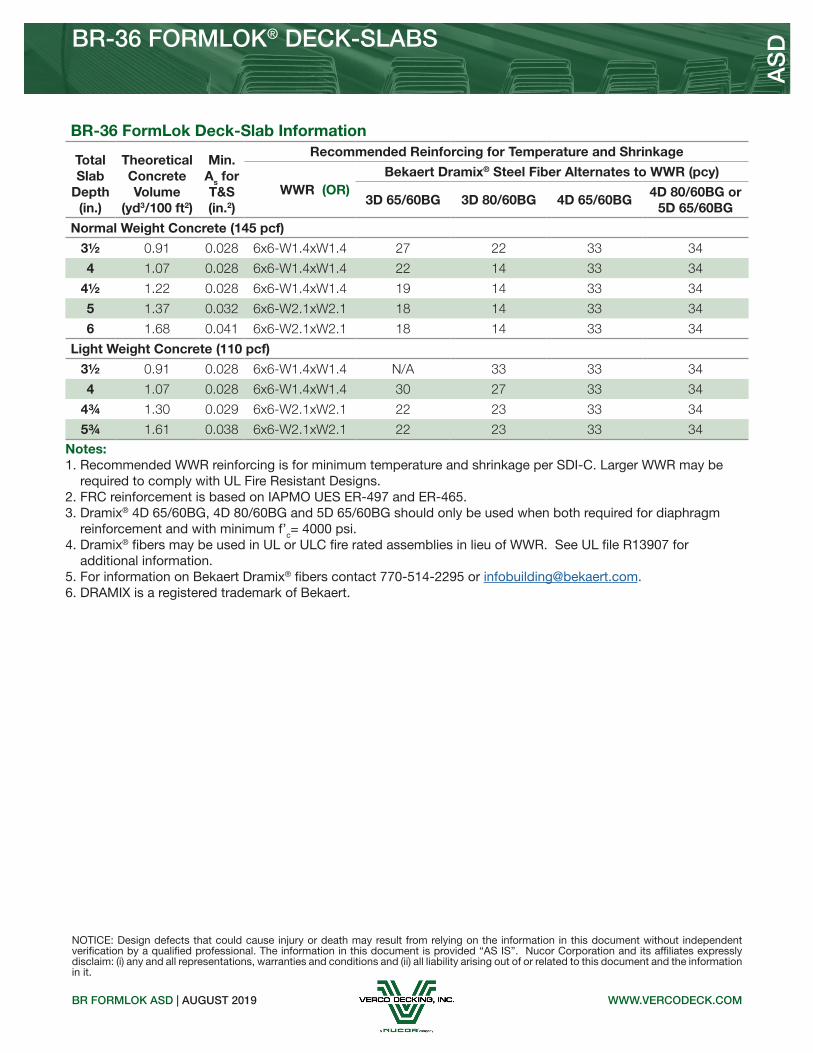
BR-36 FormLok Deck-Slab Information
Total Slab
Depth(in.)
Theoretical Concrete Volume
(yd3/100 ft2)
Min. As for T&S(in.2)
Recommended Reinforcing for Temperature and Shrinkage
WWR (OR)Bekaert Dramix® Steel Fiber Alternates to WWR (pcy)
3D 65/60BG 3D 80/60BG 4D 65/60BG4D 80/60BG or
5D 65/60BG
Normal Weight Concrete (145 pcf)
3½ 0.91 0.028 6x6-W1.4xW1.4 27 22 33 34
4 1.07 0.028 6x6-W1.4xW1.4 22 14 33 34
4½ 1.22 0.028 6x6-W1.4xW1.4 19 14 33 34
5 1.37 0.032 6x6-W2.1xW2.1 18 14 33 34
6 1.68 0.041 6x6-W2.1xW2.1 18 14 33 34
Light Weight Concrete (110 pcf)
3½ 0.91 0.028 6x6-W1.4xW1.4 N/A 33 33 34
4 1.07 0.028 6x6-W1.4xW1.4 30 27 33 34
4¾ 1.30 0.029 6x6-W2.1xW2.1 22 23 33 34
5¾ 1.61 0.038 6x6-W2.1xW2.1 22 23 33 34
AS
D
NOTICE: Design defects that could cause injury or death may result from relying on the information in this document without independent verification by a qualified professional. The information in this document is provided “AS IS”. Nucor Corporation and its affiliates expressly disclaim: (i) any and all representations, warranties and conditions and (ii) all liability arising out of or related to this document and the information in it.
Notes: 1. Recommended WWR reinforcing is for minimum temperature and shrinkage per SDI‐C. Larger WWR may be required to comply with UL Fire Resistant Designs.2. FRC reinforcement is based on IAPMO UES ER-497 and ER-465.3. Dramix® 4D 65/60BG, 4D 80/60BG and 5D 65/60BG should only be used when both required for diaphragm reinforcement and with minimum f’c= 4000 psi.4. Dramix® fibers may be used in UL or ULC fire rated assemblies in lieu of WWR. See UL file R13907 for additional information.5. For information on Bekaert Dramix® fibers contact 770-514-2295 or [email protected]. DRAMIX is a registered trademark of Bekaert.

WWW.DOVETAILDECK.COM2.0D FORMLOK ASD | AUGUST 2019
2.0D FORMLOK® DOVETAIL DECK
2.0D FORMLOK DOVETAIL DECK
Nominal Dimensions
Standard Features Optional Features• ASTM A653 SS GR 40 Min. with G90• Standard lengths – 6’-0” to 42’-0”• Tables conform to ANSI/SDI C-2017• IAPMO UES ER-423 and UL Listed
• Inquire regarding cost and lead times for: -19 gage -Short cuts < 6’-0” -Alternative metallic and painted finishes
AS
D
• Enhanced 2-Coat Polyester Paint• White Factory Primer Paint• Galvanized Finish• UL Listed
Allowable Reactions at Supports Based on Web Crippling, Rn/Ω (lb/ft)Bearing Length of Webs
One-Flange Loading Two-Flange Loading
DeckGage
End Bearing Interior Bearing End Bearing Interior Bearing
1½" 2" 3" 4" 3" 5" 1½" 2" 3" 4" 3" 5"
22 653 717 826 917 1281 1516 702 757 848 925 1567 1877
20 931 1020 1170 1296 1823 2146 1058 1136 1266 1376 2258 2690
18 1556 1697 1933 2132 3036 3544 1893 2023 2239 2422 3813 4507
16 2378 2582 2926 3215 4629 5360 3043 3237 3563 3837 5866 6880
Section Properties
Deck Gage
Deck Weight
Base Metal Thickness
Yield Strength
Effective Moment of Inertia
at Service LoadId = (2Ie+Ig)/3
Effective Section Modulus
at Fy = 40 ksiAllowable Moment
Vertical Web
Shear
wdd t Fy Id+ Id- Se+ Se- Mn+/Ω Mn-/Ω Vn/Ω
(psf) (in.) (ksi) (in4/ft) (in4/ft) (in3/ft) (in3/ft) (lb-ft/ft) (lb-ft/ft) (lb/ft)
22 2.1 0.0295 40 0.387 0.359 0.272 0.272 543 543 2896
20 2.6 0.0358 40 0.472 0.447 0.343 0.334 684 666 3498
18 3.4 0.0474 40 0.626 0.612 0.463 0.450 924 898 4584
16 4.3 0.0598 40 0.792 0.791 0.587 0.576 1172 1150 5723

WWW.DOVETAILDECK.COM
2.0D FORMLOK® DOVETAIL DECK-SLAB
2.0D FORMLOK ASD | AUGUST 2019
NORMAL WEIGHT CONCRETE (145 pcf)
Maximum Unshored Spans Composite Deck-Slab Properties
Slab DepthDeck Gage
Maximum Unshored Construction Clear Span
Concrete + Deck
Deflection Moment Shear
Id = (Icr+Iu)/2 Mno/Ω Vno/Ω
Total Topping 1 2 3 (psf) (in4/ft) (kip-ft/ft) (kip/ft)
4” 2”
22 6'-10" 7'-11" 8'-1" 46.0 5.75 3.44 3.97
20 7'-11" 8'-9" 9'-0" 46.5 6.16 4.09 3.97
18 9'-6" 10'-1" 10'-5" 47.3 6.85 5.22 3.97
16 10'-11" 11'-4" 11'-9" 48.2 7.50 6.38 3.97
51/4” 31/4”
22 6'-3" 7'-2" 7'-4" 61.1 12.19 4.44 5.21
20 7'-2" 7'-11" 8'-2" 61.6 13.03 5.29 5.21
18 8'-7" 9'-2" 9'-5" 62.4 14.42 6.79 5.21
16 9'-10" 10'-4" 10'-8" 63.3 15.75 8.32 5.21
5½” 3½”
22 6'-1" 7'-0" 7'-2" 64.1 13.87 4.64 5.38
20 7'-1" 7'-9" 8'-0" 64.6 14.81 5.53 5.46
18 8'-5" 9'-0" 9'-3" 65.4 16.39 7.11 5.46
16 9'-8" 10'-1" 10'-6" 66.3 17.90 8.73 5.46
Superimposed Allowable Load, Wn/Ω, Limited by L/360 (psf) NWC (145 pcf), f’c = 3000 psi
Total Slab
DepthDeck Gage
Span (ft-in.)
10'-0" 11'-0" 12'-0" 13'-0" 14'-0" 15'-0" 16'-0" 18'-0" 20'-0"
4”
22 229 181 145 114 91 74 61 39 22
20 269 202 155 122 98 79 65 46 33
18 299 224 173 136 109 88 73 51 37
16 327 246 189 149 119 97 80 56 40
51/4”
22 293 232 185 148 119 96 77 48 27
20 361 288 232 188 154 126 103 68 44
18 480 386 314 258 214 178 149 105 73
16 602 487 398 313 250 203 168 118 86
5½”
22 307 242 193 155 125 100 80 50 28
20 378 301 242 197 161 132 108 71 46
18 503 404 329 271 224 187 156 110 76
16 631 510 418 346 285 231 190 134 97
AS
D
Notes: 1. For high loads long term concrete creep should be considered.2. See Composite Deck-Slab Strength Web Based Solutions for alternate slabs or LRFD design.
Note: 1. Maximum unshored spans do not consider web-crippling. Required bearing should be determined based on specific span conditions.

WWW.DOVETAILDECK.COM
LIGHT WEIGHT CONCRETE (110 pcf)
2.0D FORMLOK ASD | AUGUST 2019
2.0D FORMLOK® DOVETAIL DECK-SLAB
Maximum Unshored Spans Composite Deck-Slab Properties
Slab DepthDeck Gage
Maximum Unshored Construction Clear Span
Concrete + Deck
Deflection Moment Shear
Id = (Icr+Iu)/2 Mno/Ω Vno/Ω
Total Topping 1 2 3 (psf) (in4/ft) (kip-ft/ft) (kip/ft)
4” 2”
22 7'-6" 8'-8" 8'-10" 35.4 4.43 3.30 3.97
20 8'-8" 9'-7" 9'-11" 35.9 4.79 3.90 3.97
18 10'-6" 11'-0" 11'-5" 36.7 5.36 4.96 3.97
16 11'-10" 12'-5" 12'-10" 37.6 5.89 6.02 3.97
4½” 2½”
22 7'-2" 8'-4" 8'-6" 40.0 6.11 3.68 4.32
20 8'-4" 9'-3" 9'-6" 40.5 6.59 4.36 4.47
18 10'-1" 10'-8" 11'-0" 41.3 7.36 5.55 4.47
16 11'-6" 11'-11" 12'-4" 42.2 8.09 6.76 4.47
51/4” 31/4”
22 6'-10" 7'-11" 8'-1" 46.9 9.33 4.27 4.60
20 7'-11" 8'-9" 9'-0" 47.4 10.04 5.08 5.15
18 9'-6" 10'-1" 10'-5" 48.2 11.21 6.48 5.21
16 10'-11" 11'-4" 11'-9" 49.1 12.30 7.91 5.21
Superimposed Allowable Load, Wn/Ω, Limited by L/360 (psf) LWC (110 pcf), f’c = 3000 psi
Total Slab
DepthDeck Gage
Span (ft-in.)
10'-0" 11'-0" 12'-0" 13'-0" 14'-0" 15'-0" 16'-0" 18'-0" 20'-0"
4”
22 193 145 112 88 70 57 47 33 24
20 209 157 121 95 76 61 51 35 26
18 234 175 135 106 85 69 57 40 29
16 257 193 149 117 93 76 62 44 32
4½”
22 254 200 154 121 97 79 65 45 33
20 287 216 166 131 104 85 70 49 35
18 321 241 186 146 117 95 78 55 40
16 353 265 204 160 128 104 86 60 44
51/4”
22 294 235 190 155 127 105 86 58 38
20 358 288 234 192 159 130 107 75 54
18 470 367 283 222 178 145 119 83 61
16 537 403 311 244 195 159 131 92 67
AS
D
Notes: 1. For high loads long term concrete creep should be considered.2. See Composite Deck-Slab Strength Web Based Solutions for alternate slabs or LRFD design.
Note: 1. Maximum unshored spans do not consider web-crippling. Required bearing should be determined based on specific span conditions.

WWW.DOVETAILDECK.COM2.0D FORMLOK ASD | AUGUST 2019
2.0D FORMLOK® DOVETAIL DECK-SLAB
NOTICE: Design defects that could cause injury or death may result from relying on the information in this document without independent verification by a qualified professional. The information in this document is provided “AS IS”. Nucor Corporation and its affiliates expressly disclaim: (i) any and all representations, warranties and conditions and (ii) all liability arising out of or related to this document and the information in it.
AS
D
Notes: 1. Recommended WWR reinforcing is for minimum temperature and shrinkage per SDI‐C. Larger WWR may be required to comply with UL Fire Resistant Designs.2. FRC reinforcement is based on IAPMO UES ER-497 and ER-465.3. Dramix® 4D 65/60BG, 4D 80/60BG and 5D 65/60BG should only be used when both required for diaphragm reinforcement and with minimum f’c= 4000 psi.4. Dramix® fibers may be used in UL or ULC fire rated assemblies in lieu of WWR. See UL file R13907 for additional information.5. For information on Bekaert Dramix® fibers contact 770-514-2295 or [email protected]. DRAMIX is a registered trademark of Bekaert.
2.0D FormLok Deck-Slab Information
Total Slab
Depth(in.)
Theoretical Concrete Volume
(yd3/100 ft2)
Min. As for T&S(in.2)
Recommended Reinforcing for Temperature and Shrinkage
WWR (OR)Bekaert Dramix® Steel Fiber Alternates to WWR (pcy)
3D 65/60BG 3D 80/60BG 4D 65/60BG4D 80/60BG or
5D 65/60BG
Normal Weight Concrete (145 pcf)
4 1.12 0.028 6x6-W1.4xW1.4 27 22 33 34
4½ 1.28 0.028 6x6-W1.4xW1.4 22 14 33 34
4¾ 1.35 0.028 6x6-W1.4xW1.4 20 14 33 34
5 1.43 0.028 6x6-W1.4xW1.4 19 14 33 34
51/4 1.51 0.029 6x6-W2.1xW2.1 18 14 33 34
5½ 1.58 0.032 6x6-W2.1xW2.1 18 14 33 34
6 1.74 0.036 6x6-W2.1xW2.1 18 14 33 34
6¾ 1.97 0.043 6x6-W2.9xW2.9 18 14 33 34
Light Weight Concrete (110 pcf)
4 1.12 0.028 6X6-W1.4xW1.4 N/A 33 33 34
4½ 1.28 0.028 6x6-W1.4xW1.4 30 27 33 34
5 1.43 0.028 6x6-W1.4xW1.4 23 24 33 34
51/4 1.51 0.029 6x6-W2.1xW2.1 22 23 33 34
5½ 1.58 0.032 6x6-W2.1xW2.1 22 23 33 34
6 1.74 0.036 6x6-W2.1xW2.1 22 23 33 34

WWW.DOVETAILDECK.COM3.5D FORMLOK ASD | AUGUST 2019
3.5D FORMLOK® DOVETAIL DECK
Standard Features Optional Features• ASTM A653 SS GR 40 Min. with G90• Standard lengths – 6’-0” to 42’-0”• Tables conform to ANSI/SDI C-2017• IAPMO UES ER-423 and UL Listed
• Inquire regarding cost and lead times for: -19 gage -Short cuts < 6’-0” -Alternative metallic and painted finishes
3.5D FORMLOK DOVETAIL DECK
Nominal Dimensions
AS
D
• Enhanced 2-Coat Polyester Paint• White Factory Primer Paint• Galvanized Finish• UL Listed
Allowable Reactions at Supports Based on Web Crippling, Rn/Ω (lb/ft)Bearing Length of Webs
One-Flange Loading Two-Flange Loading
DeckGage
End Bearing Interior Bearing End Bearing Interior Bearing
2" 3" 4" 5" 4" 6" 2" 3" 4" 5" 4" 6"
20 693 794 880 955 1459 1670 714 796 865 926 1724 1991
18 1168 1330 1467 1588 2422 2753 1310 1450 1568 1672 2927 3360
16 1793 2032 2233 2410 3681 4162 2137 2352 2533 2693 4515 5157
Section Properties
Deck Gage
Deck Weight
Base Metal Thickness
Yield Strength
Effective Moment of Inertia
at Service LoadId = (2Ie+Ig)/3
Effective Section Modulus
at Fy = 40 ksiAllowable Moment
Vertical Web
Shear
wdd t Fy Id+ Id- Se+ Se- Mn+/Ω Mn-/Ω Vn/Ω
(psf) (in.) (ksi) (in4/ft) (in4/ft) (in3/ft) (in3/ft) (lb-ft/ft) (lb-ft/ft) (lb/ft)
20 3.3 0.0358 40 1.762 1.646 0.676 0.781 1349 1559 3435
18 4.3 0.0474 40 2.415 2.272 0.980 1.070 1956 2136 6012
16 5.4 0.0598 40 3.133 2.968 1.317 1.377 2629 2749 8313

WWW.DOVETAILDECK.COM
3.5D FORMLOK® DOVETAIL DECK-SLAB
3.5D FORMLOK ASD | AUGUST 2019
NORMAL WEIGHT CONCRETE (145 pcf)
Maximum Unshored Spans Composite Deck-Slab Properties
Slab DepthDeck Gage
Maximum Unshored Construction Clear Span
Concrete + Deck
Deflection Moment Shear
Id = (Icr+Iu)/2 Mno/Ω Vno/Ω
Total Topping 1 2 3 (psf) (in4/ft) (kip-ft/ft) (kip/ft)
51/2” 2”
20 10'-11" 12'-2" 12'-7" 59.9 14.40 6.87 4.52
18 13'-6" 14'-3" 14'-8" 60.9 15.99 8.74 4.52
16 14'-9" 16'-1" 16'-7" 62.0 17.61 10.32 4.52
53/4” 21/4”
20 10'-9" 11'-11" 12'-4" 62.9 16.27 7.13 4.72
18 13'-3" 14'-0" 14'-5" 63.9 18.03 9.13 4.72
16 14'-7" 15'-9" 16'-4" 65.0 19.75 11.10 4.72
6” 21/2”
20 10'-6" 11'-9" 12'-1" 65.9 18.29 7.39 4.93
18 13'-0" 13'-9" 14'-2" 66.9 20.24 9.47 4.93
16 14'-5" 15'-6" 16'-0" 68.0 22.14 11.59 4.93
Superimposed Allowable Load, Wn/Ω, Limited by L/360 (psf) NWC (145 pcf), f’c = 3000 psi
Total Slab
DepthDeck Gage
Span (ft-in.)
15'-0" 16'-0" 17'-0" 18'-0" 19'-0" 20'-0" 21'-0" 23'-0" 25'-0"
51/2”
20 184 153 128 107 91 77 64 44 28
18 207 170 142 119 101 87 75 57 44
16 228 187 156 131 112 96 83 63 49
53/4”
20 190 159 134 113 95 79 66 44 28
18 233 192 160 135 114 98 85 64 50
16 255 210 175 147 125 107 93 70 55
6”
20 196 165 138 116 97 81 68 45 28
18 262 215 180 151 128 110 95 72 54
16 286 236 196 165 141 120 104 79 61
AS
D
Notes: 1. For high loads long term concrete creep should be considered.2. See Composite Deck-Slab Strength Web Based Solutions for alternate slabs or LRFD design.
Note: 1. Maximum unshored spans do not consider web-crippling. Required bearing should be determined based on specific span conditions.

WWW.DOVETAILDECK.COM
LIGHT WEIGHT CONCRETE (110 pcf)
3.5D FORMLOK ASD | AUGUST 2019
3.5D FORMLOK® DOVETAIL DECK-SLAB
Maximum Unshored Spans Composite Deck-Slab Properties
Slab DepthDeck Gage
Maximum Unshored Construction Clear Span
Concrete + Deck
Deflection Moment Shear
Id = (Icr+Iu)/2 Mno/Ω Vno/Ω
Total Topping 1 2 3 (psf) (in4/ft) (kip-ft/ft) (kip/ft)
51/2” 2”
20 12'-2" 13'-5" 13'-10" 46.2 11.18 6.37 4.52
18 14'-10" 15'-8" 16'-2" 47.2 12.69 7.86 4.52
16 15'-9" 17'-8" 18'-2" 48.3 14.26 9.44 4.52
53/4” 21/4”
20 11'-11" 13'-2" 13'-8" 48.5 12.57 6.81 4.72
18 14'-8" 15'-5" 15'-11" 49.5 14.13 8.35 4.72
16 15'-7" 17'-4" 17'-11" 50.6 15.75 9.88 4.72
8” 41/2”
20 10'-5" 11'-7" 12'-0" 69.1 31.09 9.31 5.61
18 12'-10" 13'-7" 14'-0" 70.1 34.56 11.92 6.57
16 14'-4" 15'-4" 15'-10" 71.2 37.85 14.57 6.57
Superimposed Allowable Load, Wn/Ω, Limited by L/360 (psf) LWC (110 pcf), f’c = 3000 psi
Total Slab
DepthDeck Gage
Span (ft-in.)
15'-0" 16'-0" 17'-0" 18'-0" 19'-0" 20'-0" 21'-0" 23'-0" 25'-0"
51/2”
20 144 119 99 83 71 61 52 40 31
18 164 135 112 95 80 69 59 45 35
16 184 152 126 106 90 77 67 51 39
53/4”
20 162 134 111 94 80 68 59 45 35
18 182 150 125 105 90 77 66 50 39
16 203 168 140 118 100 86 74 56 44
8”
20 262 221 188 160 137 117 99 71 50
18 353 302 259 224 194 168 146 110 82
16 446 384 332 283 241 206 178 135 105
AS
D
Notes: 1. For high loads long term concrete creep should be considered.2. See Composite Deck-Slab Strength Web Based Solutions for alternate slabs or LRFD design.
Note: 1. Maximum unshored spans do not consider web-crippling. Required bearing should be determined based on specific span conditions.

WWW.DOVETAILDECK.COM3.5D FORMLOK ASD | AUGUST 2019
3.5D FORMLOK® DOVETAIL DECK-SLAB
NOTICE: Design defects that could cause injury or death may result from relying on the information in this document without independent verification by a qualified professional. The information in this document is provided “AS IS”. Nucor Corporation and its affiliates expressly disclaim: (i) any and all representations, warranties and conditions and (ii) all liability arising out of or related to this document and the information in it.
AS
D
Notes: 1. Recommended WWR reinforcing is for minimum temperature and shrinkage per SDI‐C. Larger WWR may be required to comply with UL Fire Resistant Designs.2. FRC reinforcement is based on IAPMO UES ER-497 and ER-465.3. Dramix® 4D 65/60BG, 4D 80/60BG and 5D 65/60BG should only be used when both required for diaphragm reinforcement and with minimum f’c= 4000 psi.4. Dramix® fibers may be used in UL or ULC fire rated assemblies in lieu of WWR. See UL file R13907 for additional information.5. For information on Bekaert Dramix® fibers contact 770-514-2295 or [email protected]. DRAMIX is a registered trademark of Bekaert.
3.5D FormLok Deck-Slab Information
Total Slab
Depth(in.)
Theoretical Concrete Volume
(yd3/100 ft2)
Min. As for T&S(in.2)
Recommended Reinforcing for Temperature and Shrinkage
WWR (OR)Bekaert Dramix® Steel Fiber Alternates to WWR (pcy)
3D 65/60BG 3D 80/60BG 4D 65/60BG4D 80/60BG or
5D 65/60BG
Normal Weight Concrete (145 pcf)
51/2 1.44 0.028 6x6-W1.4xW1.4 27 22 33 34
53/4 1.52 0.028 6x6-W1.4xW1.4 25 16 33 34
6 1.60 0.028 6x6-W1.4xW1.4 22 14 33 34
61/2 1.75 0.028 6x6-W1.4xW1.4 19 14 33 34
7 1.91 0.032 6x6-W2.1xW2.1 18 14 33 34
71/4 1.98 0.034 6x6-W2.1xW2.1 18 14 33 34
71/2 2.06 0.036 6x6-W2.1xW2.1 18 14 33 34
8 2.22 0.041 6x6-W2.1xW2.1 18 14 33 34
Light Weight Concrete (110 pcf)
51/2 1.44 0.028 6x6-W1.4xW1.4 N/A 33 33 34
53/4 1.52 0.028 6x6-W1.4xW1.4 34 30 33 34
6 1.60 0.028 6x6-W1.4xW1.4 30 27 33 34
61/2 1.75 0.028 6x6-W1.4xW1.4 23 24 33 34
7 1.91 0.032 6x6-W2.1xW2.1 22 23 33 34
71/2 2.06 0.036 6x6-W2.1xW2.1 22 23 33 34
8 2.22 0.041 6x6-W2.1xW2.1 22 23 33 34