Dynamic Load Simulator: Actuation Strategies and...
9
Dynamic Load Simulator: Actuation Strategies and Applications Swaroop K. Yalla 1 and Ahsan Kareem, M.ASCE 2 Abstract: The development of a multiple-actuator dynamic load simulator DLS, for the simulation of correlated dynamic loads on small-scale structural components and substructures, or on bench-scale system assemblage is presented in this paper. Conceptually, the DLS employs actuators to simulate a desired dynamic loading environment due to wind, waves, or earthquakes, which in special cases may serve as a replacement for conventional facilities such as wind tunnels, wave tanks and shaking tables. The actuation strategy of the DLS is based on force-control rather than the customary motion control displacement/velocity scheme. The load simulator is ideal for structural components and for systems that can be idealized as lumped mass systems. An actuation strategy for the DLS based on an innovative scheme that utilizes the coupled control system is developed. For implementation of this scheme, the nonlinear control system toolbox in MATLAB is used. In this scheme, the tuning of control parameters in the time domain is carried out by solving a constrained optimization problem. A suite of loading protocols that includes sinusoidal, two-point correlated fluctuations in wind loading, earthquake induced loading and loads characterized by strong non-Gaussian features is simulated by employing the control scheme introduced here. The load simulation examples presented here demonstrate that the loading time histories generated by utilizing the DLS matched the target values with high fidelity. DOI: 10.1061/ASCE0733-93992007133:8855 CE Database subject headings: Dynamic loads; Simulation; Feedback control; Structural control. Introduction In view of increasing vulnerability of the built environment to devastating forces of nature, the structural engineering commu- nity is faced with the major challenge of finding new techniques and devices for testing and validating structural performance under dynamic load effects. Simulation systems that can mimic the natural environment in the laboratory are often very important for gauging the reliability of structural components and systems. Other applications may include the evaluation of motion control devices or the fatigue life of building components. In the area of wind engineering, efforts to model both the structural resistance and loading have not been successfully ac- complished thus far due to the limited capacity of wind tunnels to house a large scale model and to generate winds strong enough to investigate structural capacities Cermak et al. 1999. On the other hand, testing devices for structural components, e.g., roofing panels, have been developed using pulsating pressure chambers Cook et al. 1988. Though successful in testing structural resis- tance, the aerodynamic loading imparted to the structural compo- nents such as roofing elements is generally spatially uniform with desired temporal fluctuations. In certain situations, this uniformity of pressure may not provide data that is representative of the full-scale conditions. Other tests dealing with the mean wind loads on wood frame housing have been conducted using gantry frames around the structure with attached actuators Reardon 1988; Bartlett 2002. This approach has been either limited to static loading applications or dynamic sinusoidal block loading for cyclical fatigue testing. The most commonly used method for seismic testing of struc- tures is the use of shaking tables in which ground motion is si- mulated by the table acceleration. However, the size of the structure is scaled by the capacity of the shaking table. Therefore, the advantage of shaking table experiments may be offset by the associated scaling problem. Large size shaking tables offer an attractive solution to scaling issues and help to minimize the in- teraction between the test structure and the shaking table. The advent of electromechanically driven shaking tables have ushered the table-top small scale shaking tables era, which are attractive for small scale structural testing, especially for the proof-of-the- concept or structural control problems, but these systems may bear the shortcomings resulting from the structure-table interac- tion issues. In earthquake engineering, alternatives to shaking table tests that include effective force method, pseudodynamic method, pseudodynamic hybrid method, or real-time online pseudody- namic methods for testing of large-scale structural components, structural sub or super assemblies, and in some case full or large scale structures, have been evolving over the last few decades. A focus on a number of these concepts is central to the NSF George E. Brown, Jr. Network for Earthquake Engineering Simulation initiative to develop total testing-analysis-visualization-display environments with provisions for tele-experimentation. One of 1 Morgan Stanley, 1585 Broadway, New York, New York 10036; formerly, Research Assistant, NatHaz Modeling Laboratory, Univ. of Notre Dame, IN 46556. 2 Robert M. Moran Professor of Engineering, NatHaz Modeling Laboratory, Univ. of Notre Dame, IN 46556. E-mail: [email protected] Note. Associate Editor: Henri P. Gavin. Discussion open until January 1, 2008. Separate discussions must be submitted for individual papers. To extend the closing date by one month, a written request must be filed with the ASCE Managing Editor. The manuscript for this paper was submitted for review and possible publication on May 24, 2005; approved on May 17, 2006. This paper is part of the Journal of Engineering Mechanics, Vol. 133, No. 8, August 1, 2007. ©ASCE, ISSN 0733-9399/2007/8-855– 863/$25.00. JOURNAL OF ENGINEERING MECHANICS © ASCE / AUGUST 2007 / 855
Transcript of Dynamic Load Simulator: Actuation Strategies and...
Dynamic Load Simulator:Actuation Strategies and Applications
Swaroop K. Yalla1 and Ahsan Kareem, M.ASCE2
Abstract: The development of a multiple-actuator dynamic load simulator �DLS�, for the simulation of correlated dynamic loads onsmall-scale structural components and substructures, or on bench-scale system assemblage is presented in this paper. Conceptually, theDLS employs actuators to simulate a desired dynamic loading environment due to wind, waves, or earthquakes, which in special casesmay serve as a replacement for conventional facilities such as wind tunnels, wave tanks and shaking tables. The actuation strategy of theDLS is based on force-control rather than the customary motion control �displacement/velocity� scheme. The load simulator is ideal forstructural components and for systems that can be idealized as lumped mass systems. An actuation strategy for the DLS based on aninnovative scheme that utilizes the coupled control system is developed. For implementation of this scheme, the nonlinear control systemtoolbox in MATLAB is used. In this scheme, the tuning of control parameters in the time domain is carried out by solving a constrainedoptimization problem. A suite of loading protocols that includes sinusoidal, two-point correlated fluctuations in wind loading, earthquakeinduced loading and loads characterized by strong non-Gaussian features is simulated by employing the control scheme introduced here.The load simulation examples presented here demonstrate that the loading time histories generated by utilizing the DLS matched the targetvalues with high fidelity.
DOI: 10.1061/�ASCE�0733-9399�2007�133:8�855�
CE Database subject headings: Dynamic loads; Simulation; Feedback control; Structural control.
Introduction
In view of increasing vulnerability of the built environment todevastating forces of nature, the structural engineering commu-nity is faced with the major challenge of finding new techniquesand devices for testing and validating structural performanceunder dynamic load effects. Simulation systems that can mimicthe natural environment in the laboratory are often very importantfor gauging the reliability of structural components and systems.Other applications may include the evaluation of motion controldevices or the fatigue life of building components.
In the area of wind engineering, efforts to model both thestructural resistance and loading have not been successfully ac-complished thus far due to the limited capacity of wind tunnels tohouse a large scale model and to generate winds strong enough toinvestigate structural capacities �Cermak et al. 1999�. On theother hand, testing devices for structural components, e.g., roofingpanels, have been developed using pulsating pressure chambers�Cook et al. 1988�. Though successful in testing structural resis-tance, the aerodynamic loading imparted to the structural compo-
1Morgan Stanley, 1585 Broadway, New York, New York 10036;formerly, Research Assistant, NatHaz Modeling Laboratory, Univ. ofNotre Dame, IN 46556.
2Robert M. Moran Professor of Engineering, NatHaz ModelingLaboratory, Univ. of Notre Dame, IN 46556. E-mail: [email protected]
Note. Associate Editor: Henri P. Gavin. Discussion open until January1, 2008. Separate discussions must be submitted for individual papers. Toextend the closing date by one month, a written request must be filed withthe ASCE Managing Editor. The manuscript for this paper was submittedfor review and possible publication on May 24, 2005; approved on May17, 2006. This paper is part of the Journal of Engineering Mechanics,Vol. 133, No. 8, August 1, 2007. ©ASCE, ISSN 0733-9399/2007/8-855–
863/$25.00.JOUR
nents such as roofing elements is generally spatially uniform withdesired temporal fluctuations. In certain situations, this uniformityof pressure may not provide data that is representative of thefull-scale conditions. Other tests dealing with the mean windloads on wood frame housing have been conducted using gantryframes around the structure with attached actuators �Reardon1988; Bartlett 2002�. This approach has been either limited tostatic loading applications or dynamic sinusoidal block loadingfor cyclical fatigue testing.
The most commonly used method for seismic testing of struc-tures is the use of shaking tables in which ground motion is si-mulated by the table acceleration. However, the size of thestructure is scaled by the capacity of the shaking table. Therefore,the advantage of shaking table experiments may be offset by theassociated scaling problem. Large size shaking tables offer anattractive solution to scaling issues and help to minimize the in-teraction between the test structure and the shaking table. Theadvent of electromechanically driven shaking tables have usheredthe table-top small scale shaking tables era, which are attractivefor small scale structural testing, especially for the proof-of-the-concept or structural control problems, but these systems maybear the shortcomings resulting from the structure-table interac-tion issues.
In earthquake engineering, alternatives to shaking table teststhat include effective force method, pseudodynamic method,pseudodynamic hybrid method, or real-time online pseudody-namic methods for testing of large-scale structural components,structural sub or super assemblies, and in some case full or largescale structures, have been evolving over the last few decades. Afocus on a number of these concepts is central to the NSF GeorgeE. Brown, Jr. Network for Earthquake Engineering Simulationinitiative to develop total testing-analysis-visualization-display
environments with provisions for tele-experimentation. One ofNAL OF ENGINEERING MECHANICS © ASCE / AUGUST 2007 / 855
these techniques with established success is the pseudodynamictest method in which the test is performed quasistatically, yetprovides a realistic simulation of the response of structures underdynamic loading provided the material is not very sensitive to therate of loading �Takanashi and Nakashima 1987; Mahin et al.1989�. In these systems, actuators at floor levels introduce inertialdynamic forces. The equations of structural motion are numeri-cally evaluated on line and the floor displacements are calculated.These displacements are then applied to the structures by actua-tors and the load cells on the actuators measure the forces neces-sary to impose the required deformations. These are then used inthe next time step of the numerical calculation and the process iscontinued. This is an indirect approach and has limitations as asystem’s exact parameters are an essential prerequisite for theoperation of this system. In some cases, the rate of loading thatinfluences structural behavior may not be adequately modeled.Moreover, the method is highly sensitive to measurement andcontrol errors.
A major advantage of the pseudodynamic test is that it allowssubstructuring of the system, where a physical model is built as apart of the structure and the rest of the structure is modeled nu-merically. More recently, real-time substructure tests have beendeveloped involving a hybrid experimental modeling of actuator-excitation and computer simulation proceeding on a commontime scale �Horiuchi et al. 1996; Darby et al. 1999; Williams andBlakeborough 2001; Nakashima 2001�. In a study by Dimig et al.�1999�, an effective force technique �EFT� similar to the dynamicload simulator �DLS� was introduced for applying seismic forcesat the lumped masses of a multidegree of freedom �MDOF� sys-tem. However, that study was verified only on single degree offreedom systems. The EFT is being extended to nonlinear systems�Zhao et al. 2004�. A real-time dynamic hybrid testing system hasbeen developed by implementing combined physical testing andcomputational simulation to enable dynamic testing of substruc-tures including the rate and inertial effects while taking into con-sideration the overall system �Reinhorn et al. 2004�. This testingsystem relies on a new force control scheme with predictive com-pensation procedure that facilitates the implementation of thereal-time feature.
The hardware in the loop �HIL� is another development, whichrefers to a simulation technique in which some of the systemcomponents are numerically simulated while others are physicallymodeled with appropriate interface conditions. This is similar toreal-time substructuring where a physical test and a numericalmodel interact in real time. HIL developed out of a hybrid be-tween control prototyping and software-in-the-loop simulations�Isermann 1999�. It is routinely used in aerospace and automotivecontrol in embedded systems as an inexpensive and reliable rapid-prototyping technique for product development. It is ideallysuited for testing structures with dampers �Yalla 2001�. One canbuild a virtual structure in a computer model and the nonlinearelements such as dampers, base-isolators, etc., can be included inthe physical model �Yalla and Kareem 2001�. Some of the advan-tages of HIL simulation over conventional testing methods are thecost and time savings in repeated simulations as it offers on-the-fly tuning of parameters.
The experimental testing schemes described in the precedingparagraphs are still evolving and are primarily limited to a singleactuator with the potential to expand to multiple actuators. Forexample, in a real-time substructuring scheme most of the struc-tural system is numerically modeled and the complex part of thesystem, e.g., a base isolation device, is physically modeled utiliz-
ing a single actuator �e.g., Nakashima 2001�. Extension to a856 / JOURNAL OF ENGINEERING MECHANICS © ASCE / AUGUST 2007
MDOF system is theoretically straightforward as the effectiveforce at each floor level depends on the ground acceleration andthe structural masses only. Nonetheless, structural masses in thisscheme have to be accurately included and the actuators at higherfloors may require specialized large-flow servovalves along withhigh quality controllers. Although fully correlated loads at differ-ent levels of the structure may be used in the case of earthquakes,for other loads like wind and waves, the actuator control strategymust incorporate correlation among load levels. Therefore, decou-pling of interacting control loops is extremely important for theeffective simulation of correlated loads at multiple locations forapplication to MDOF systems.
To address some of these challenges, a pilot DLS was devel-oped by the writers for simulating wind, wave, or earthquakeloads on structures. The pilot DLS was based on a force-feedbackcontrol system that could directly mimic dynamic loads �Reinholdand Kareem 1996; Kareem et al. 1997�. The loads generated by aDLS can be introduced to a structure through a reaction wall organtry frame �Kareem et al. 1997�. This system was envisioned asa low-cost test simulator, which could be readily assembled usingexisting infrastructure of a typical structural dynamics laboratory.In this paper, first a brief introduction of the force-feedback basedcontrol methodology is presented, which is followed by an intro-duction of various control strategies used for controlling multipleactuator systems. For efficient and robust simulations, a new typeof coupled control system �CCS�, using the Nonlinear ControlSystem toolbox in MATLAB �The MathWorks, Inc., Natick,Mass�, is developed. This control scheme is used for the simula-tion of a suite of loading protocols utilizing the DLS, which isvalidated through comparisons with target load signatures.
Force-Feedback System
In the control of dynamic systems, an appropriate feedback iscustomarily introduced to effectively achieve the necessary con-trol objectives �Fig. 1�. Typically, there are two types of controlschemes, i.e., the motion �displacement/velocity� control or force�and torque� control. In most structural engineering applications,e.g., shaking tables and other large testing equipment, motioncontrol is commonly employed. This choice may have resultedfrom the relative ease with which the position/velocity of thesystem can be controlled in comparison with the force. This hasled to some obvious shortcomings concerning the control of shak-ing tables as noted in its inability to match accurately the pre-scribed accelerations �Spencer and Yang 1998�. This problem maybe ameliorated in force-feedback systems as in this case wherethe inertial force is supplied to control the actuators. Moreover, inmany applications, force control is critical for maintaining precise
Fig. 1. Force-feedback system
application of force, e.g., in robotics and in precision machining

equipment where a large force may be exerted due to a slighterror in motion, resulting in either damage to the tool or unac-ceptable product quality.
DLS System Configuration
The development of a first generation of dynamic load simulatorprototype was presented in Yalla et al. �2001�. The prototype wastested using an aluminum beam with end supports that permittedconvenient changes in the beam span. This system has been ex-tended to study a multiinput multioutput �MIMO� system asshown in Fig. 2. A cantilever type structure with two lumpedmasses is attached to actuators. The actuator assembly is in turnmounted on a rigid reaction frame �Fig. 2�a��.
The system employs electromechanical type actuators com-prised of a ball screw couched in two linear motion guide race-ways on each side, which provide an extremely rigid and highlyaccurate actuator transfer function. The actuators are driven by dcservomotors, which are attached to the motor mounting flanges.The computer-controlled system was implemented using WinConreal-time system, which uses MATLAB/SIMULINK for controlsystem prototyping. The C-code was generated and subsequentlydownloaded to the digital signal processing chip by utilizingthe Real-time Workshop and Real-time interface from Math-works, Inc. Data acquisition was accomplished using a WinCon,Quanser, Inc., Markham, Ontario, compatible MultiQ-3 boardequipped with 8 single ended analog inputs, 8 analog outputs,16 bit digital input/output, as well as 8 encoder inputs. A SigLab,Spectral Dynamics, San Jose, CA, 20–22 spectrum analyzer wasused for obtaining the frequency response functions of the variouscomponents of the system. Target time histories of the desiredforces are inputted to the computer, which are converted to analogsignals using a digital-to-analog converter. These signals are thenamplified and fed into the servomotors, which drive the actuators.The stroke of actuators creates forces on the test specimen/structure while an axial load cell placed in between the actuatorand the structure, measures the actual force imparted to the struc-ture and sends the signal back to the computer using an analog-to-digital converter. The error between the measured force and the
Fig. 2. �a� DLS facility; �b� schematic of the DLS experimental setup
applied force is corrected using a feedback control system.
JOUR
Actuator Control Strategies
This section discusses briefly some of the control strategies thatcan be used to control multiple actuator loading systems. Thesesystems can be categorized as multiple actuator single-axes�MASA� or multiple actuators multiple-axis �MAMA� systems.Although MAMA systems represent general loading conditions,e.g., loads on automobiles, the DLS configuration in this study bydesign is uni-axial. Therefore the focus in the ensuing sectionswill be on MASA type systems. The DLS concept presented herecan be extended to MAMA configuration. Two main types ofactuators used to drive these systems can be categorized as elec-tromechanical or servohydraulic actuators. In this study, electro-mechanical actuators, each consisting of a servomotor and a ballscrew, are employed. Mechanical systems other than ball screwsare possible, e.g., rack and pinion, belts and pulleys, etc. Alterna-tively, for some applications linear motors can be used as theyoffer high accuracy and a linear transfer function �Cruz 1997�.
There are a number of issues, particular with MASA/MAMAsystems, which pose serious challenges in their control. In orderto optimally control these systems, some prior information of theloading and the test structure itself �system identification� isneeded. This is usually obtained before the actual test commencesor during testing �for on-line adaptive nonlinear type control�.Furthermore, in a single-actuator single-axes system, the controlsystem can be designed based on judgment or using well-definedrules such as the Ziegler-Nichols scheme for Proportional IntegralDerivative �PID� controllers �Dorf and Bishop 1998�. However,for MASA/MAMA systems this becomes an arduous task sincethe number of control gains to be manipulated becomes large.This aspect is further complicated as multiple exciters result inintroducing interactions �cross-coupling� among various compo-nents of the MIMO system. This implies that for an accuratecontrol, the system should have the capability of suppressing un-desired force contributions induced by other actuators �cross-coupling compensation�. Various types of control systems usedfor multiple-exciter system can be classified as open-loop, itera-tive closed-loop and real-time closed-loop �e.g., Hamma et al.1996�. These systems are briefly described here for completeness.
Open-Loop ControlIn an open-loop control scheme, the signals used to drive theactuators do not benefit from any observed output of the system;rather these are generated directly by prescribed function genera-tors. This type of control systems may be suited for very lowfrequency type loading signals and are not recommended for anydynamic testing involving higher frequencies due to potentialinstabilities.
Iterative Closed-Loop ControlTraditionally, iterative closed-loop control schemes have beenused extensively to control MASA/MAMA systems �e.g.,Fletcher 1990�. The central design of iterative closed-loopschemes is outlined in Fig. 3. The function Hyu���, which definesthe transfer function between measured forces �output� and con-trol forces �input� to the servomotors, is estimated for the closedloop system. The error between the desired and measured systemresponse is iteratively minimized by sequentially updating thedriver signal. It is important to note that the impedance matrixcalculation requires clipping at low frequencies prior to matrix
inversion, which is necessitated by the influence of measurementNAL OF ENGINEERING MECHANICS © ASCE / AUGUST 2007 / 857
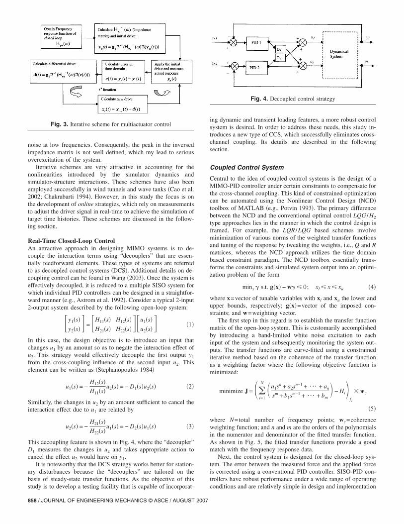
noise at low frequencies. Consequently, the peak in the inversedimpedance matrix is not well defined, which my lead to seriousoverexcitation of the system.
Iterative schemes are very attractive in accounting for thenonlinearities introduced by the simulator dynamics andsimulator-structure interactions. These schemes have also beenemployed successfully in wind tunnels and wave tanks �Cao et al.2002; Chakrabarti 1994�. However, in this study the focus is onthe development of online strategies, which rely on measurementsto adjust the driver signal in real-time to achieve the simulation oftarget time histories. These schemes are discussed in the follow-ing section.
Real-Time Closed-Loop ControlAn attractive approach in designing MIMO systems is to de-couple the interaction terms using “decouplers” that are essen-tially feedforward elements. These types of systems are referredto as decoupled control systems �DCS�. Additional details on de-coupling control can be found in Wang �2003�. Once the system iseffectively decoupled, it is reduced to a multiple SISO system forwhich individual PID controllers can be designed in a straightfor-ward manner �e.g., Astrom et al. 1992�. Consider a typical 2-input2-output system described by the following open-loop system:
�y1�s�y2�s� � = �H11�s� H12�s�
H21�s� H22�s� ��u1�s�u2�s� � �1�
In this case, the design objective is to introduce an input thatchanges u1 by an amount so as to negate the interaction effect ofu2. This strategy would effectively decouple the first output y1
from the cross-coupling influence of the second input u2. Thiselement can be written as �Stephanopoulos 1984�
u1�s� = −H12�s�H11�s�
u2�s� = − D1�s�u2�s� �2�
Similarly, the changes in u2 by an amount sufficient to cancel theinteraction effect due to u1 are related by
u2�s� = −H21�s�H22�s�
u1�s� = − D2�s�u1�s� �3�
This decoupling feature is shown in Fig. 4, where the “decoupler”D1 measures the changes in u2 and takes appropriate action tocancel the effect u2 would have on y1.
It is noteworthy that the DCS strategy works better for station-ary disturbances because the “decouplers” are tailored on thebasis of steady-state transfer functions. As the objective of this
Fig. 3. Iterative scheme for multiactuator control
study is to develop a testing facility that is capable of incorporat-
858 / JOURNAL OF ENGINEERING MECHANICS © ASCE / AUGUST 2007
ing dynamic and transient loading features, a more robust controlsystem is desired. In order to address these needs, this study in-troduces a new type of CCS, which successfully eliminates cross-channel coupling. Its details are described in the followingsection.
Coupled Control System
Central to the idea of coupled control systems is the design of aMIMO-PID controller under certain constraints to compensate forthe cross-channel coupling. This kind of constrained optimizationcan be automated using the Nonlinear Control Design �NCD�toolbox of MATLAB �e.g., Potvin 1993�. The primary differencebetween the NCD and the conventional optimal control LQG /H2
type approaches lies in the manner in which the control design isframed. For example, the LQR /LQG based schemes involveminimization of various norms of the weighted transfer functionsand tuning of the response by tweaking the weights, i.e., Q and Rmatrices, whereas the NCD approach utilizes the time domainbased constraint paradigm. The NCD toolbox essentially trans-forms the constraints and simulated system output into an optimi-zation problem of the form
minx � s.t. g�x� − w� � 0; xl � x � xu �4�
where x=vector of tunable variables with xl and xu the lower andupper bounds, respectively; g�x�=vector of the imposed con-straints; and w=weighting vector.
The first step in this regard is to establish the transfer functionmatrix of the open-loop system. This is customarily accomplishedby introducing a band-limited white noise excitation to eachinput of the system and subsequently monitoring the system out-puts. The transfer functions are curve-fitted using a constrainediterative method based on the coherence of the transfer functionas a weighting factor where the following objective function isminimized:
minimize J = ��i=1
N �a1sn + a2sn−1 + ¯ + an
sm + b1sm−1 + ¯ + bm� − Hi�
f i
� wc
�5�
where N=total number of frequency points; wc=coherenceweighting function; and n and m are the orders of the polynomialsin the numerator and denominator of the fitted transfer function.As shown in Fig. 5, the fitted transfer functions provide a goodmatch with the frequency response data.
Next, the control system is designed for the closed-loop sys-tem. The error between the measured force and the applied forceis corrected using a conventional PID controller. SISO-PID con-trollers have robust performance under a wide range of operating
Fig. 4. Decoupled control strategy
conditions and are relatively simple in design and implementation

for reducing the steady-state error and improving the transientresponse �Dorf and Bishop 1998�. The gains of the PID controller,i.e., proportional gain Kp, integral gain Ki, and derivative gain Kd,are chosen so that the measured output force tracks the inputvoltage command signal. Whereas, a general MIMO PID control-ler can be described by the following transfer function
u�s� = �Kp +Ki
s+
Kd�100s��s + 100� �e�s� �6�
where e�s�=error between the reference or desired output and themeasured output. The scalar PID gains now become matrix gains.However, as alluded to earlier, tuning the gains for MIMO-PIDcontrollers is a difficult task as there are no well-defined tuningrules similar to those available for SISO-PID controllers.
The MIMO-PID controller parameter-tuning problem was ad-dressed utilizing the NCD toolbox in MATLAB. The control de-sign scheme is shown schematically in Fig. 6. The optimizationloop iteratively searches for the optimum set of tuning parametersthat satisfy the time-domain constraints in the output response.The MIMO-PID controller for tracking problems involves se-quentially inputting a step command. When the first channel steps�i.e., a step input is applied�, the first output should track the stepwhile the other channels should reject this input and vice versa.Fig. 7 shows the tuning of the system parameters before and afteroptimization. Before optimization, the system response is coupled
Fig. 5. Open loop transfer functions �experimental and curve fitted�
and does not meet the requirements introduced by constraints.
JOUR
This means that when the input step is introduced at the firstactuator, the second actuator also produces a response to the ex-citation as noted in Fig. 7�a�. On the other hand, when the pro-posed optimization is introduced, the NCD toolbox effectivelytunes 12 parameters �4 parameters each in Kp, Ki, and Kd matri-ces� under a total of 6,012 constraints to provide the solution,which results in an optimum performance. As noted in Fig. 7�b�,with optimization in place, the two actuators respond to step in-puts independent of each other. The nonlinear control systemstoolbox also permits inclusion of inherent uncertainties in thevarious plant parameters, which results in a more robust design.Uncertainties were not explicitly considered as a part of this studyas the transfer function of the system was estimated experimen-tally. The MIMO-PID gain matrices before and after optimizationare given as• Before optimization
Kp = �4.0 0
0 3.0� ; Ki = �1.0 0
0 1.0� ; Kd = �0.1 0
0 0.1�
• After optimization
Fig. 6. Nonlinear control design methodology
Fig. 7. Closed loop response of two outputs to sequential steploading prior to and after optimization
NAL OF ENGINEERING MECHANICS © ASCE / AUGUST 2007 / 859

Kp = �4.16 − 9.7
0.80 4.2� ; Ki = � 4.2 − 0.11
4.93 8.96� ;
Kd = � 0.43 − 0.17
− 0.15 0.09�
It is noteworthy that the gains matrices in the MIMO controllerare fully populated, where the off-diagonal terms are responsiblefor compensating the cross-channel coupling.
Applications
In order to demonstrate the proposed scheme to control multipleactuators, representative loading time histories are generated uti-lizing the DLS. It is important to bear in mind that unlike con-ventional test facilities, e.g., wind tunnels, wave tanks, shakingtables etc., where distributed space-time variations of the aero-dynamic, hydrodynamic pressure fields or inertial loads are intro-duced, the DLS provides discrete point loads to produce globalload characteristics by taking into account the overall spatio-temporal correlation �Fig. 8�. Accordingly, the load simulatoris ideal for structural components and for systems that can beidealized as lumped mass systems. A suite of different loadingcases including sinusoidal, wind loading with high and lowcorrelations, seismic loading and non-Gaussian loading wereinvestigated.
Sinusoidal LoadingThe initial testing of DLS was conducted using sinusoidal loadswith potential application to cyclical fatigue testing of compo-nents. Fig. 9 shows the desired signals applied to the two actua-tors with sinusoidal frequencies of 1.5 and 1.0 Hz. It is noted thatthe force tracking, i.e., actual output signals measured by theforce transducers, match the input signals quite well with theexception of slight attenuation in the amplitudes around thepeaks.
Wind LoadingAs wind flows past a structure, it manifests loads through spa-tiotemporally distributed fluctuations in surface pressure. For aload bearing structural system, a pointed load at each floor level isestimated based on the tributary area and appropriate correlationof the fluctuating pressure. For the time history analysis, theseload fluctuations can be synthesized through wind tunnel testsutilizing pressure models equipped with multi-scanning systems.Alternatively, the time histories may be digitally simulated basedon prescribed spectral correlation.
In this study, time-histories for numerically simulated fluctu-
Fig. 8. �a� Environmental loading; �b� discrete loading system
ating components of wind forces for a two degrees of freedom
860 / JOURNAL OF ENGINEERING MECHANICS © ASCE / AUGUST 2007
�2DOF� system were introduced as input to the DLS system. Thetime histories of wind forces were generated using a multivariatesimulation based on the prescribed power spectral density matrixwith prescribed correlation structure �Gurley and Kareem 1998�.Two loading cases were considered: wind loads with high andlow correlation. In a typical wind excited structure, the correlationbetween the wind loads at two points decreases as the distancebetween the two points increases. The low correlation signalswere selected from two well-separated locations whereas thehigher correlation case involved two closely spaced locations.Fig. 10 shows the target and simulated records, which demon-strates that the two actuators reproduced the two input signalswith their respective correlation level in each case with highfidelity.
Earthquake LoadingThe motion of a structural system subjected to ground motion xg
is given by
MX�t� + CX�t� + KX�t� = − Mxg �7�
in which M, C, K=mass, damping, and stiffness matrices, respec-tively. X�t� and its derivatives represent relative motion compo-nents of the different degrees of freedom with respect to theground. A system subjected to a base motion may be replaced byan equivalent fixed-base structure with the effective force Feff�t�applied to structural lumped masses. This is similar to the EFTutilized in Dimig et al. �1999�. In this manner, the effective forcesare applied directly to a fixed-base structural model using actua-tors operated under a force control scheme. A major advantageof this scheme lies in the fact that since the effective force at eachlevel depends only on the ground acceleration and the structuralmasses; it is independent of any nonlinearity that may exist inthe structural behavior under loads. Therefore, these loads canbe ascertained in advance, precluding the need for any onlinecomputations. An added advantage is that since loads at eachlevel are fully correlated, the need for coupled control schemes iseliminated.
As illustrated here, the response of a system to a given groundmotion may be replicated exactly by applying an effective forceto each mass of the system, which is equal to the product of the
Fig. 9. Sinusoidal load simulation with actuator frequencies: Top—1.5 Hz and bottom—1.0 Hz
mass at that level and the ground acceleration. In order to validate

the simulation of seismic loads using the DLS system, the first10 s of the El Centro Earthquake time history were used as aninput at both levels of the DLS system �Fig. 11�. The resultsdemonstrate that the system was able to reproduce the transientearthquake loading with high accuracy.
Non-Gaussian LoadingThe preceding example of wind loading signals was characterized
Fig. 10. Simulation of wind loading
by Gaussian fluctuations. However, some of the local pressure
JOUR
fluctuations on buildings may exhibit strong non-Gaussian fea-tures, which are distinctly different from Gaussian. These featuresare characterized by skewness and kurtosis �Gurley et al. 1997�. Itis also noteworthy that the load fluctuations derived from thesynthesis of these pressure fluctuations may still exhibit strongnon-Gaussian features as the spatio-temporal correlation of thesepressure fields over structural surfaces precludes validity of theCentral Limit Theorem. In order to examine the ability of the
igh correlation; �b� low correlation
: �a� hNAL OF ENGINEERING MECHANICS © ASCE / AUGUST 2007 / 861
862 / JOURNAL OF ENGINEERING MECHANICS © ASCE / AUGUST 2007
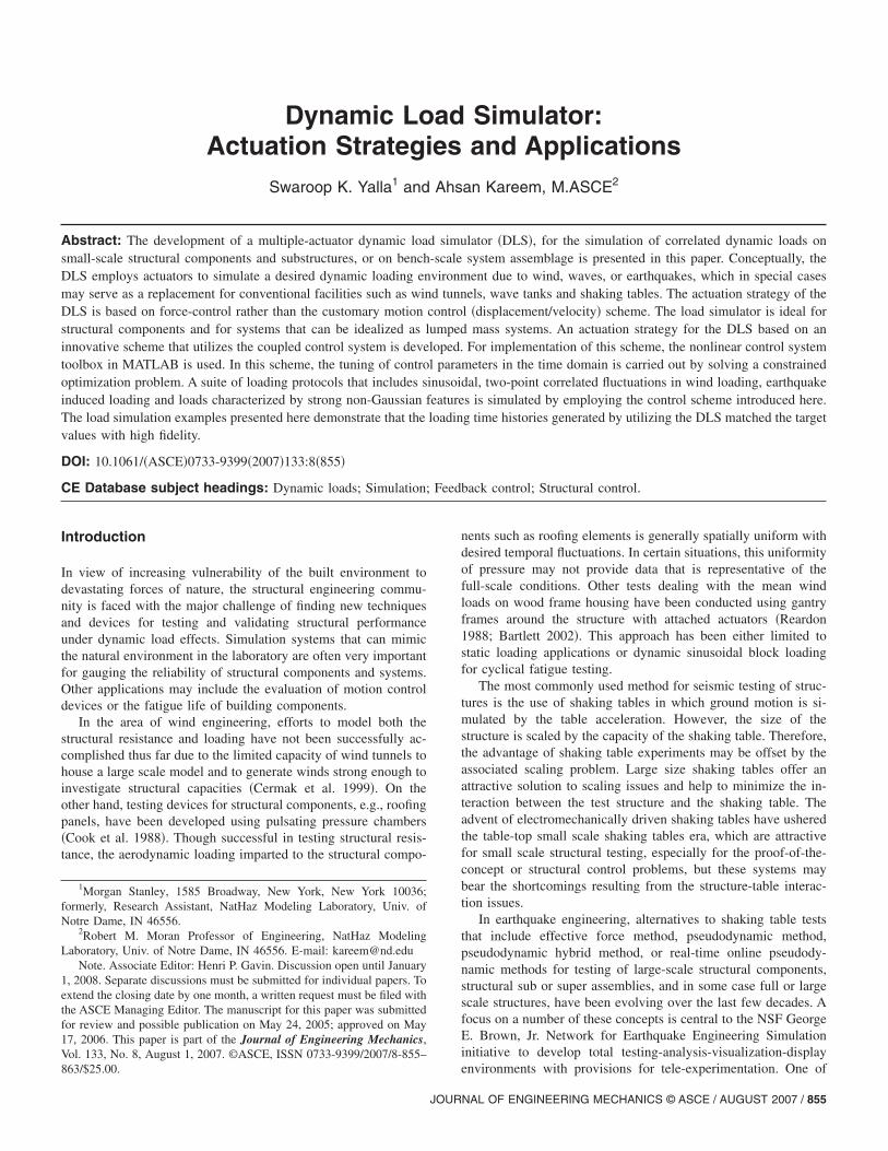
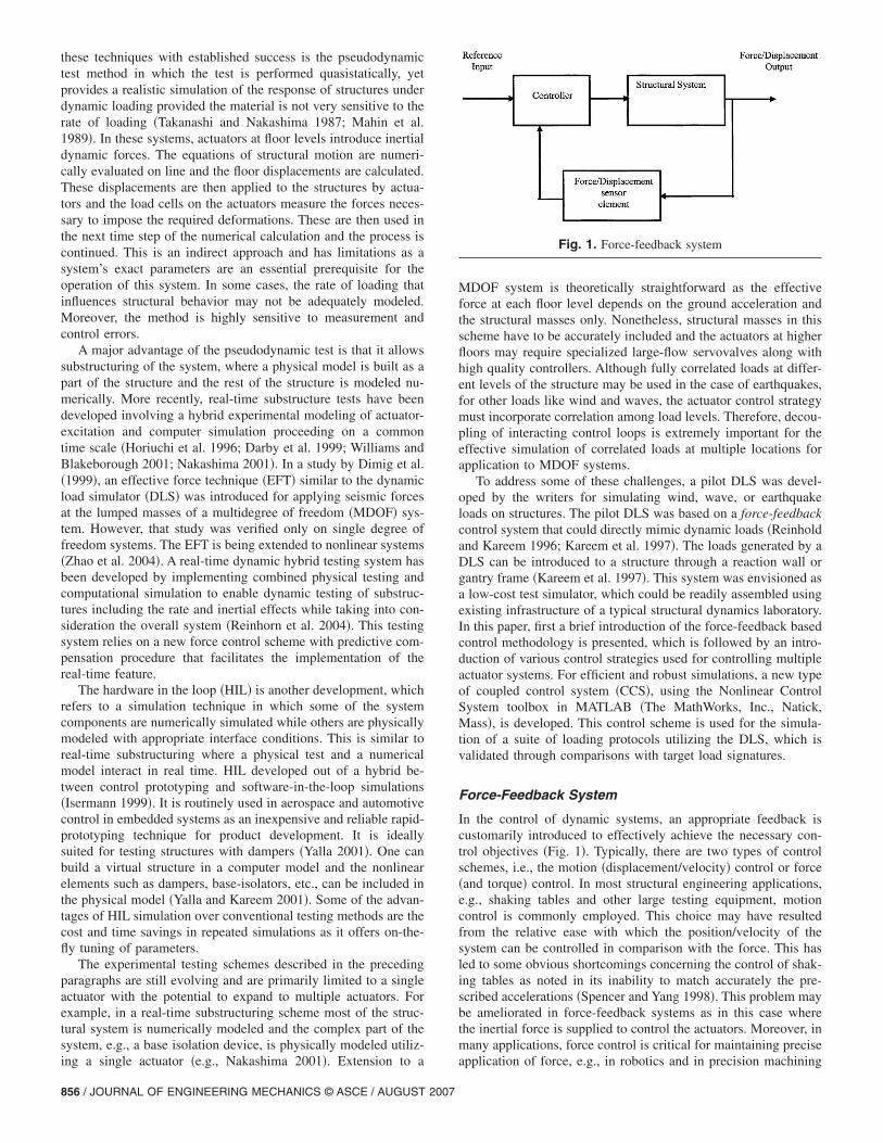
DLS to faithfully track force fluctuations characterized bythe non-Gaussian aspects, simulated records based on the pre-scribed spectral and probabilistic features were utilized to derivethe DLS actuators. Fig. 12 demonstrates the high quality ofload simulation as it chronicles two target correlated non-Gaussian pressure fluctuations �Fig. 12�a��. Comparisons of simu-lated and target signatures zoomed for two representative regionsin Figs. 12�b and c�. It is noteworthy that the actuators capturethe non-Gaussian features with high fidelity. An example of waveinduced loads on structures for either linear �Gaussian� or nonlin-ear �non-Gaussian� wave has not been included here, but suchapplications are immediate as demonstrated here for a similarloading signature �Kareem et al. 1998�.
Conclusions
The development of a small-scale bench-top testing facility,namely the DLS, was described in this paper. Various typesof control strategies used for controlling single/multiple actuatorsin a testing facility utilizing force-feedback were examined. Anew type of CCS using the nonlinear control system toolbox in
ignals; �b� and �c� zoomed comparisons between target and measured
Fig. 11. Simulation of earthquake loading
Fig. 12. �a� Original time histories of two partially correlated nonGaussian s
MATLAB was introduced in this study. In this approach, thetime-domain control parameter-tuning problem was solved as aconstrained optimization problem. A suite of loading protocolsthat included sinusoidal, wind loading with high and low correla-tion, earthquake loading and non-Gaussian type loading wassimulated and verified experimentally on the DLS system. Thegenerated loads exhibited a good agreement with the desired tar-get load signatures. An immediate extension of this concept maybe realized by placing multiple actuators at a closely spaced gridto further accentuate spatial correlation of loading. Applicationsto wave-related processes are immediate. The demonstrated suc-cess in generating a wide range of signals with high repeatabilityand robustness suggests that the DLS concept will be ideal fortesting structural components under multiple-correlated loads.Further, it also holds promise of prototyping this small-scale sys-tem to a large-scale real-time DLS that utilizes high capacity elec-tromechanical actuators with existing reaction-support systems instructural testing laboratories. Such systems would be invaluabletools for testing performance of structures under the demandposed by wind, wave and earthquake loads. The robustness in theperformance of such a loading system for components or systemsthat experience yielding needs to be further investigated.
Acknowledgments
The writers were supported in part by Grant No. CCS622895 bythe Lockheed Martin Idaho Technologies and the NSF Grant No.CMS 95-03779. This support is gratefully acknowledged. Anyopinions, findings, or recommendations expressed in this paperare those of the writers and do not necessarily represent the viewsof the sponsors.
References
Astrom, K. J., Hang, C. C., Persson, P., and Ho, W. K. �1992�. “Towardsintelligent PID control.” Automatica, 28�1�, 1–9.
Bartlett, M. �2002�. “Testing load paths in full-scale houses.” Proc.,Workshop on Mitigating Housing Losses in Extreme Natural Events,Institute for Catastrophic Loss Reduction, Toronto.
Cao, S., Nushi, A., Kikugawa, H., and Matsuda, Y. �2002�. “Reproductionof wind velocity history in a multiple fan wind tunnel.” J. Wind. Eng.Ind. Aerodyn., 90�12–15�, 1719–1729.
Cermak, J. E., et al. �1999�. Review of the need for a large-scale testfacility for research on the effects of extreme winds on structures,National Research Council, National Academy Press, Washington,D.C.
Chakrabarti, S. �1994�. Offshore structural modeling, World Scientific,River Edge, N.J.
Cook, N. J., Keevil, A. P., and Stobart, R. K. �1988�. “BRERWULF—Thebig bad wolf.” J. Wind. Eng. Ind. Aerodyn., 29�1–3�, 99–107.
Cruz, I. S. �1997�. “Linear motors: A good choice for motion and positioncontrol.” I&CS �10�, 53–56.
Darby, A. P., Blakeborough, A., and Williams, M. S. �1999�. “Real-timesubstructure tests using hydraulic actuator.” J. Eng. Mech., 125�10�,1133–1139.
Dimig, J., Shield, C., French, C., Bailey, F., and Clark, A. �1999�. “Ef-fective force testing: A method of seismic simulation for structuraltesting.” J. Struct. Eng., 125�9�, 1028–1037.
Dorf, R. C., and Bishop, R. H. �1998�. Modern control systems, AddisonWesley, Reading, Mass.
Fletcher, J. N. �1990�. “Global simulation: New technique for multiaxiscontrol.” Sound Vib., November, 1990, 26–33.
Gurley, K., and Kareem, A. �1998�. “Simulation of correlated non-
JOUR
Gaussian pressure fields.” Meccanica, 33�3�, 309–317.Gurley, K., Tognarelli, M. A., and Kareem, A. �1997�. “Analysis and
simulation tools for wind engineering.” Probab. Eng. Mech., 12�1�,9–32.
Hamma, G. A., Stroud, R. C., Underwood, M. A., Woyski, W. B., Taus-cher, R. C., and Cappel, K. L. �1996�. “A review of multi-axis/multiexciter vibration technology.” Sound Vib. April, 1996, 20–27.
Horiuchi, T., Nakagawa, M., Sugano, M., and Konno, T. �1996�. “Devel-opment of real-time hybrid experimental system with actuator delaycompensation.” Proc., 11th World Conf. on Earthquake Engineering,Paper No. 660, International Association for Earthquake Engineering.
Isermann, R., Schaffnit, J., and Sinsel, S. �1999�. “Hardware-in-the-loopsimulation for the design and testing of engine-control systems.” Con-trol Eng. Pract., 7�5�, 644–653.
Kareem, A., Hsieh, C., and Tognarelli, M. �1998�. “Frequency-domainresponse analysis of offshore platform in non-Gaussian seas.” J. Eng.Mech., 124�6�, 668–683.
Kareem, A., Kabat, S., and Haan, F. L., Jr. �1997�. “Dynamic wind loadsimulator.” Proc., 8th U.S. National Conf. on Wind Engineering,Baltimore, Md.
Mahin, S. A., Shing, P. B., Thewalt, C. R., and Hanson, R. D. �1989�.“Pseudodynamic test method-current status and future directions.”J. Struct. Eng., 115�8�, 2113–2127.
Nakashima, M. �2001�. “Development, potential and limitations of real-time online �pseudodynamic� testing.” Philos. Trans. R. Soc. London,Ser. A, 359�1786�, 1851–1867.
Potvin, A. F. �1993�. Nonlinear control design toolbox, The MathworksInc., Natick, Mass.
Reardon, G. F. �1988�. “Simulated wind loading on houses.” Proc., Int.Conf. Housing and Construction in the Age of Technology, GoldCoast.
Reinhorn, A. M., Sivaselvan, M. V., Liang, Z., and Shao, X. �2004�.“Real-time dynamic hybrid testing of structural systems.” Proc., 13thWorld Conf. on Earthquake Engineering, Vancouver, B.C., Canada,Paper No. 1644, International Association for EarthquakeEngineering.
Reinhold, T. A., and Kareem, A. �1996�. “Next generation of wind testfacilities: A feasibility study.” Proc., 2nd Int. Workshop of StructuralControl, Next Generation of Intelligent Structures, International Asso-ciation for Structural Control, Hong Kong.
Spencer, B. F., and Yang, G. �1998�. “Earthquake simulator control bytransfer function iteration.” Proc., 12th Engineering Mechanics Conf.Engineering Mechanics: A Force for the 21st Century, E. H.Murakami and J. E. Luco, eds., 766–769.
Stephanopoulos, G. �1984�. Chemical process control: An introduction totheory and practice, Prentice Hall, Inc., Englewood Cliffs, N.J.
Takanashi, K., and Nakashima, M. �1987�. “Japanese activities on on-linetesting.” J. Eng. Mech., 113�7�, 1014–1032.
Wang, Q.-G. �2003�. Decoupling control, Lecture Notes in Control andInformation Science, Vol. 285, Springer, New York.
Williams, M. S., and Blakeborough, A. �2001�. “Laboratory testing ofstructures under dynamic loads: An introductory review.” Philos.Trans. R. Soc. London, Ser. A, 359�1786�, 1651–1669.
Yalla, S. K. �2001�. “Liquid dampers for mitigation of structuralresponse: Theoretical development and experimental validation.”Thesis, Dept. of Civil Engineering, Univ. of Notre Dame, NotreDame, IN.
Yalla, S. K., and Kareem, A. �2001�. “Hardware-in-the-loop simulation:A case study for liquid dampers.” Proc., Joint Applied Mechanics andMaterials Summer Conf., ASCE/ASME, San Diego.
Yalla, S. K., Kareem, A., Kabat, S., and Haan, F. L., Jr. �2001�. “Dynamicload simulator: Development of a prototype.” J. Eng. Mech., 127�12�,1310–1315.
Zhao, J., French, C., Shield, C., and Posberg, T. �2004�. “Effective forcetesting with nonlinear velocity feedback compensation.” Proc., 13thWorld Conf. on Earthquake Engineering, Vancouver, B.C., Canada,
Paper No. 268, International Association for Earthquake Engineering.NAL OF ENGINEERING MECHANICS © ASCE / AUGUST 2007 / 863