4 ECM Automated Clutch · permissible clutch actuation load. The actuator-operated SAC clutch...
22
85 The Automated Clutch - The New LuK ECM Dipl. Ing. Burkhard Kremmling Dr. Techn. Robert Fischer Introduction Manual transmissions have the advantage over automatic transmissions in that the driver has free choice of gears and does not feel dictated to by an automaton. Already in the 60s, automotive manufacturers began to offer automated clutch operating systems designed to simplify vehicle operation. In the past, interest in these systems has been very limited. These early systems were functionally inadequate, maintenance-intensive and prone to frequent repairs; disadvantages that could be eliminated with modern vehicle electronics. In the meantime, automated clutch operating systems have been used in formula 1 and rally vehicles, which proves that they are equal to the most demanding conditions. Traffic density is constantly increasing, and currently has reached a level where automated clutch systems become interesting. The data illustrated in Figure 1 are taken from the Allgemeine Deutsche Automobil-Club (ADAC) study [1] in which all significant traffic jams on the German Autobahn system were recorded during the summer vacation travel period. Figure 1 shows the number of traffic jams that were longer than 20 km. This number increased by 20 % in only a year, i.e. from 75 traffic jams in 1992 to 90 traffic jams in 1993. The ECM system relieves drivers of having to concentrate on operating the vehicle and thus allows them to turn their attention to the actual traffic situation. This leads to the conclusion that ECM will decrease accident frequency.
Transcript of 4 ECM Automated Clutch · permissible clutch actuation load. The actuator-operated SAC clutch...

85
The Automated Clutch - The New LuK ECM
Dipl. Ing. Burkhard Kremmling Dr. Techn. Robert Fischer
Introduction Manual transmissions have the advantage over automatic transmissions in that the driver has free choice of gears and does not feel dictated to by an automaton.
Already in the 60s, automotive manufacturers began to offer automated clutch operating systems designed to simplify vehicle operation. In the past, interest in these systems has been very limited.
These early systems were functionally inadequate, maintenance-intensive and prone to frequent repairs; disadvantages that could be eliminated with modern vehicle electronics.
In the meantime, automated clutch operating systems have been used in formula 1 and rally vehicles, which proves that they are equal to the most demanding conditions.
Traffic density is constantly increasing, and currently has reached a level where automated clutch systems become interesting.
The data illustrated in Figure 1 are taken from the Allgemeine Deutsche Automobil-Club (ADAC) study [1] in which all significant traffic jams on the German Autobahn system were recorded during the summer vacation travel period.
Figure 1 shows the number of traffic jams that were longer than 20 km. This number increased by 20 % in only a year, i.e. from 75 traffic jams in 1992 to 90 traffic jams in 1993.
The ECM system relieves drivers of having to concentrate on operating the vehicle and thus allows them to turn their attention to the actual traffic situation. This leads to the conclusion that ECM will decrease accident frequency.

86
1992 1993year
0
50
100
7590
num
ber o
f tra
ffic
jam
s >
20 k
m
Figure 1: Number of traffic jams longer than 20 km on the German Autobahn system during the summer vacation season (June - September); comparison for the years 1992 and 1993 [1].
When LuK's ECM was presented initially at the last colloquium in 1990 [2], the potential and technical possibilities of the system were demonstrated.
LuK initially developed the ECM in conjunction with hydraulic actuation systems.
In 1993, LuK succesfully introduced the ECM into production with the BMW ALPINA B12 (Figure 2). So far more than 60 % of all ALPINA B12 vehicles have been ordered with the ECM - the so-called SHIFT-TRONIC option - and the number is rising. This is proof that customers want the system.
Atlas Fahrzeugtechnik in Werdohl (AFT) has taken over the development and production of the control device for the ALPINA ECM system. AFT has proven its competence as a development partner and supplier.
Although the hydraulic actuation system has the advantage of dynamic response, it has the disadvantage of being very complex. Consequently, the cost reduction potential of hydraulic actuation systems is less than for other kinds of operating systems.
In order to expand the market base for electronic clutch management, the costs of the system have to be reduced. Consequently LuK has conducted a cost-benefits analysis.

87
Figure 2: ALPINA B12 SHIFT-TRONIC
Functions of the ECM Although the advantages offered by the ECM system should be familiar, here is a summary of its functions .
Increased comfort in stop-and-go traffic The system simplifies stop-and-go driving because it is no longer possible to kill the engine when the vehicle starts off or stops.
Improved maneuverability LuK has developed a strategy similar to the operation of an automatic transmission, whereby, the vehicle can creep forward when in gear even if the driver is not pushing on the gas pedal. The great advantage of this "creep strategy" is that it is easier for drivers to inch forward because they only have to operate one pedal - the brake pedal.
The control system completely dissipates the creep torque with a slight time delay when the foot brake or parking brake is activated. This feature eliminates the disadvantage of increased clutch wear and fuel consumption due to creeping.

88
Rattle and boom prevention Controlled clutch slip can be used to eliminate irritating noises such as gear rattle and body boom.
Improved tip-in/back-out performance Tip-in/back-out performance can be improved using a special clutch control to eliminate surging (chuckle).
Potential advantages for transmission developers The ECM system provides a significant cost reduction potential for transmission developers:
In conventional manual transmissions with pedal-activated clutches, it is possible for drivers to misuse the clutch by changing gears with the clutch partially closed. The transmission developer has to account for a certain number of improper shift operations when designing the transmission.
The ECM system ensures that the driver can't forget to disengage the clutch when he changes gears. This means that the synchronizer does not have to be so robust, which results in cost savings and reduces shift effort.
When using a pedal-operated clutch, it is also possible that the driver's foot can slip from the clutch pedal during start-up. This kind of "jack-rabbit start" causes short-term torque peaks throughout the entire power train that could be many times the maximum engine torque.
With the ECM, this kind of "jack-rabbit start load" does not occur. This, coupled with a special tip-in/back-out strategy, reduces torque peaks in the drive train. As a result, cost can be reduced because the transmission and axles do not need to be "over-designed".
The potential for reducing fuel consumption and emissions The ECM system can be equipped with options that will significantly reduce both fuel consumption and harmful emissions (see the chapter Outlook of this paper).
What are the limits on system costs? LuK assumes that the electronic clutch management system has not been widely used in the past because the costs for the system were almost as high as the costs for an automatic transmission.

89
In order for the ECM to establish itself, system target costs must be significantly reduced to the point where they are more comparable to the costs for a manual transmission (Figure 3).
ECM,1992
newLuK-ECM
5-speedmanualtrans-
mission
4-speedautomatic
trans-m ission
cost
s
Figure 3: Cost estimate: manual transmission / ECM / automatic transmission
Result: The new LuK ECM Cost effective hardware was the primary requirement in achieving a drastic cost reduction. This process involved limiting the performance of the clutch actuator to the level absolutely required of the system, coupled with a reduction in the number of sensors needed.
As a result, the requirements imposed on the control strategy increased considerably, which means that instead of high performance or numerous sensors, more intelligent control is needed.
One important development goal of the new LuK ECM has been to use the existing production transmission without modifications. This simplifies logistics for the automotive manufacturer, minimizes development effort and decreases investments.
Additional development goals included:
• using the same gear shift lever
• keeping weight low
• maintaining a compact, variable package size
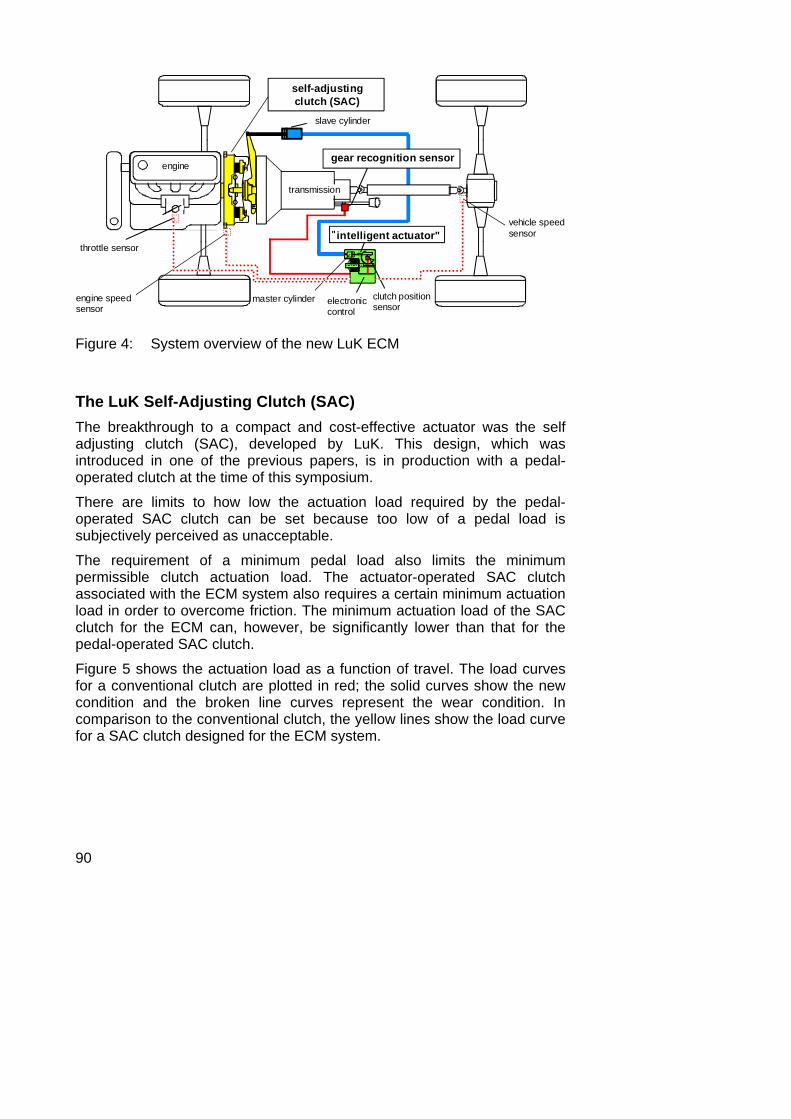
Figure 4 shows the results in the form of an overview of the new LuK ECM.
90
throttle sensor"intelligent actuator"
engine
transmission
slave cylinder
self-adjusting clutch (SAC)
gear recognition sensor
clutch positionsensorelectronic
control
vehicle speedsensor
engine speed sensor
master cylinder
Figure 4: System overview of the new LuK ECM
The LuK Self-Adjusting Clutch (SAC) The breakthrough to a compact and cost-effective actuator was the self adjusting clutch (SAC), developed by LuK. This design, which was introduced in one of the previous papers, is in production with a pedal-operated clutch at the time of this symposium.
There are limits to how low the actuation load required by the pedal-operated SAC clutch can be set because too low of a pedal load is subjectively perceived as unacceptable.
The requirement of a minimum pedal load also limits the minimum permissible clutch actuation load. The actuator-operated SAC clutch associated with the ECM system also requires a certain minimum actuation load in order to overcome friction. The minimum actuation load of the SAC clutch for the ECM can, however, be significantly lower than that for the pedal-operated SAC clutch.
Figure 5 shows the actuation load as a function of travel. The load curves for a conventional clutch are plotted in red; the solid curves show the new condition and the broken line curves represent the wear condition. In comparison to the conventional clutch, the yellow lines show the load curve for a SAC clutch designed for the ECM system.

91
actuation position
new condition
wear
0
conventional
0
actu
atio
n lo
ad
Figure 5: Comparison of the actuation load curves for a conventional clutch and for the SAC clutch designed to be used with the ECM system
Based on the special conditions described above for the ECM actuator-operated SAC clutch, a load reduction of about 2/3 compared to the maximum actuation load of a conventional clutch can be achieved.
In comparison to the conventional clutch, in which the actuation load increases as the facing wears (red curves), the actuation load of the SAC clutch (yellow curve) is constant over the entire service life of the component.
An additional advantage of the SAC clutch is the option of increasing the facing wear reserve without increasing the actuation load at the same time.
The clutch actuator: A mass produced electric motor By reducing the clutch release load, it is possible to use a low power electric motor (Figure 4). LuK's development partner, BOSCH, which manufactures the small motor used, produces more than 4 million of these units per year.
There is a hydraulic master cylinder located on the actuator housing. The master cylinder is connected with the clutch slave cylinder by hydraulic lines, which allows the actuator to be installed almost anywhere in the

92
vehicle. The only requirement is that its ambient temperature does not exceed 100 ºC.
The basic actuator design makes it possible to use a cable instead of master cylinder and slave cylinder.
The dynamic response of the actuator described here is lower than for the hydraulic clutch operation. This apparent disadvantage of slower dynamic response can, however, be compensated for, using the motto "brains instead of brawn", illustrated in Figure 6, by using an intelligent control system.
brawn
brains
Figure 6: Brains instead of brawn!
Solving several problems at once: "torque follow up system" As the result of design safety factors and tolerances, which must be accounted for when designing the clutch, the maximum torque that can be transmitted by a clutch, amounts to two to three times the maximum engine torque. Nevertheless, while driving, the average engine torque only amounts to a fraction of the maximum engine torque. If the clutch is "fully closed" (this means, able to transmit the maximum torque), the transmittable clutch torque is many times higher than the actual engine torque.
The basic idea behind "torque follow up system" is: instead of closing the clutch far enough to accommodate the maximum transmittable clutch torque, it is possible to only close it to the point where the transferable clutch torque is only slightly greater than the actual engine torque.

93
Effect during gear change As soon as the driver lets up on the gas, the engine torque is reduced and the "torque follow up system" function automatically adjusts the clutch by opening it slightly. This means that when the system recognizes the drivers desire to shift gears, the clutch is already partly open. Consequently, the reduced adjustment speed of the new ECM system is sufficient to completely disengage the clutch, even for fast gear changes.
Effect during tip-in/back-out Figure 7 shows simulation results for tip-in in 2nd gear.
These graphs compare the following control variants:
• Clutch closed (top pair of graphs)
• controlled slip (middle pair of graphs)
• "torque follow up system" (bottom pair of graphs)
In each set of graphs, the top graph shows the engine and transmission speed curves as a function of time. Each bottom graph shows the longitudinal acceleration.
As shown in Figure 7 above, rapid changes in engine torque are followed by unpleasant surge oscillations, which are sometimes called "chuckle".
The controlled slip system (Figure 7, center), which was introduced at the last LuK Colloquium in 1990, is capable of preventing surge oscillation. The disadvantage of TCI is that it requires a continuous, relatively great amount of slip. This control variant makes it necessary to drive with continuous slip, even in speed and load ranges where slip would not be necessary to eliminate noise.
The effect of "torque follow up system" (Figure 7, bottom) is similar to that of a torque limiter. Slip occurs only when there are rapid changes in engine torque and only for a short time. In comparison to controlled slip system, "torque follow up system" offers advantages with respect to fuel consumption and wear.
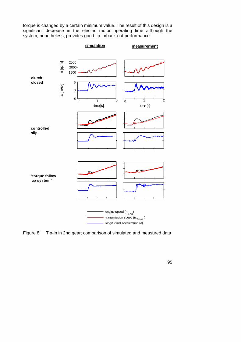
The graphs on the left in Figure 8 show the simulation results already represented in Figure 7. In comparison to these results, the graphs on the right hand side illustrate the measured results for the same driving situation (Tip-in, 2nd gear). It is clear that there is a good correlation between the simulation data (Figure 8, left) and the measured data (Figure 8, right).

94
controlledslip
150020002500
time [s]
-5
0
5
0 1 2
clutch closed
"torque follow up system"
engine speed (n )
transmission speed (n )
longitudinal acceleration (a)
Eng.
Trans.
n [rp
m]
a [m
/s²]
Figure 7: Simulation of a tip-in cycle in 2nd gear. Comparison between the control variants "closed clutch", "controlled slip" and "torque follow up system".
"Torque follow up system" utilizes hysteresis, which means that, in contrast to controlled slip system, the clutch torque is only shifted if the engine
95
torque is changed by a certain minimum value. The result of this design is a significant decrease in the electric motor operating time although the system, nonetheless, provides good tip-in/back-out performance.
2500
simulation measurement
controlledslip
"torque follow up system"
15002000
time [s]
-5
0
5
0 1 2time [s]
0 1 2
clutchclosed
engine speed (n )
transmission speed (n )
longitudinal acceleration (a)
Eng.
Trans.
n [rp
m]
a [m
/s²]
Figure 8: Tip-in in 2nd gear; comparison of simulated and measured data

96
Integrating the control device in the actuator housing Two factors play an important role in achieving the next significant step in the development of the clutch actuating system:
• the introduction of a low power electric motor
• installation of the actuator at a remote site (i.e., removed from the release fork or the concentric slave cylinder) in an area whose ambient temperature does not exceed 100 °C.
As a result of these factors, the actuator and the complete ECM control device with the engine electronics have been combined to form a single unit, which is called the intelligent actuator.
direct current motor electronic
clutch travel sensor master cylinder
direct current motor electronic
clutch travel sensor master cylinder
direct current motor electronic
clutch travel sensor master cylinder
Figure 9: Unit consisting of an actuator and a control device ( intelligent actuator )
The most important advantages of this integration include:
• reduced cable complexity and expense
• fewer electrical connections
• fewer components
• increased protection against system malfunction
• reduced system costs
• reduced additional weight.
The complete actuator/control unit was developed by BOSCH.
97
No transmission modifications required! In order to avoid modifying the production transmission, the following demanding problems had to be solved:
• moving the clutch travel measurement from the slave cylinder to the "intelligent actuator" (Figure 4), which means placing it upstream of the master cylinder
• eliminating the transmission input speed sensor • moving the gear recognition sensor to the shift rod from its pre-
vious location directly on the transmission.
These measures have simplified the adaptation of the ECM to a new vehicle, but the software requirements increase at the same time. Moving the clutch position measurement from the slave cylinder to the intelligent actuator will be used as an example to explain this situation:
The master cylinder attached to the actuator, i.e. the "new" measuring position for the clutch position, and the slave cylinder are connected by a hydraulic line that varies in length depending on the vehicle in question. The fluid used in the system (brake fluid) is subject to changes in volume due to temperature influences, which results in significantly inaccurate clutch position measurement signals. Losses due to compressibility, which are for the most part dependent on the air entrained in the brake fluid, also cause false measuring results as well as fluid losses due to the compensation orifice in the master cylinder.
Figure 10 shows the measured data curves for the ECM vehicle. The measurements were stored with the vehicle parked immediately after a brisk drive.
The figure illustrates the false signal values for the clutch position, which are attributible to moving the sensor. The top graph shows the deviation Δs between the true clutch position measured on the slave cylinder and the virtual clutch position measured on the master cylinder and plotted as a function of time.
At the point in time t=0, the vehicle was parked and the measurement was started with the engine running. The relatively low fluid temperature of about 25 ºC at the beginning of the measurement cycle (shown in the bottom graph in Figure 10), is attributable to cooling of the line between the master and slave cylinder as a result of air flow while driving.
However, heat built up from the engine and exhaust system cause the fluid temperature to rise significantly again (Figure 10, bottom). As a result, the brake fluid expands in volume, which causes the deviation Δs between the master and the slave cylinder to increase.

98
As shown in the measurement, the position deviation Δs amounts to about 6 mm at time t ≈ 18 min. If one takes into account that the entire adjustment range of the clutch only amounts to about 20 mm, it is obvious what a great effect this has on the measurement.
time [min] 10 200
0
20
40
60
80
10 20
02
4
6
8
Δ S = Deviation between the position of the slave and the master cylinder
ϑ Fluid
= Average fluid temperature in the line between the master and the slave cylinder
time [min]
s [m
m]
Δ[°
C]
Flui
dϑ
Figure 10: Falsification of measuring signals for clutch position as a result of shifting the measuring point from the slave to the master cylinder.

99
At t ≈ 19 min, the engine is shut off and the clutch is closed. The excess brake fluid escapes via the compensation orifice in the master cylinder into the reservoir. When t ≈ 21 min, the clutch is opened again. Directly thereafter, the position deviation Δs is initially 0, but then it increases again immediately.
LuK has developed a strategy whereby the clutch characteristic, that is the relationship between the clutch position and the transmitted torque is constantly adapted. This involves determining the actual clutch torque during clutch slip phases based on dynamic torque equilibrium. This adaptation process has made it possible to fully compensate for the significant deterioration in signal quality described above. This strategy has been implemented in the ALPINA B 12 production design, where it functions without any problems.
Additional sensors required: Reduced to only one The LuK ECM only requires one additional sensor for gear recognition. All other sensor signals required by the control system can be picked off the existing control devices (Figure 4). As cited above, gear recognition is now measured on the shift rod rather than on the transmission.
The advantages of reducing the number of ECM-specific sensors include:
• fewer electrical connections, which reduces the sources of poten-tial problems
• simplified installation and easier wiring
Two analog potentiometers are used as the sensor elements in the gear selection recognition system. These sensors have proven themselves for long-term automative applications as throttle sensors. They indicate two shift lever directions - "shift" and "select". Analog measurement eliminates the need for system adjustments to compensate for production variations and changes in the transmission kinematics between the shifter and the gear recognition sensors, for example, due to temperature-related material expansion and to wear. Compensation for these changes are made continuously during operation based on extreme position checks.

100
As already mentioned, a series of additional signals are required for the ECM system controls, as shown in part by the broken line in Figure 4. These signals can all be picked off from existing control devices:
• engine speed
• vehicle speed
• throttle position
• engine torque
• parking brake engagement
• brake engagement
Eliminating shift lever changes The new LuK system recognizes the drivers desire to shift gears based on the travel of the shift lever.
The sensor designed to recognize the desire to shift gears that was included in earlier ECM systems can be eliminated in the new LuK ECM with the exception of special cases.
An intelligent software program prevents incorrect system responses due to leaving a hand on the shift lever or uneven drive surfaces. The system also opens the clutch at the appropriate time when the driver actually does signal the wish to change gears.
Simple torsion damper design A holistic view of the mechanical and electronic systems has led to the recognition that the use of a simple torsion damper will make it possible to reduce the speed ranges where slip is necessary to eliminate noise. The torsion damper can also be designed only to accommodate partial loads.
Comparing different systems Figure 11 compares various clutch automation systems. The illustration at the top of the drawing shows a hydraulic actuation system (LuK's 1st generation ECM). The center illustration shows a conventional electric motor actuator without the SAC clutch and the bottom illustration shows the new LuK system.
101
The comparison shows that a hydraulic actuator (top of Figure 11) requires a number of cost-intensive components that contribute to a weight of about 5 kg, such as:
• an electric pump
• a hydraulic valve body
• an accumulator
• a pressure sensor
• a proportional valve.
With conventional electric motor actuation without the SAC clutch (Figure 11, center), the 6 kg weight is higher than for the hydraulic actuation system.
If the size of the new LuK system (bottom of Figure 11) is compared with the conventional electric motor system, (Figure 11, center), the simplifications due to the SAC becomes apparent, as illustrated by the following advantages:
• simpler installation and wiring
• fewer electrical connections and consequently, fewer sources for potential problems
• fewer detail parts
• considerable cost reductions
• significantly decreased weight (about 2 kg)
• lower space requirements
The reduction in sensors by eliminating the transmission speed sensor has further simplified the new LuK system.

102
conven-tionalelectricmotor
hydraulicsystem
actuationsystem
design weight[kg] sensors
3
3 ... 4
≈ 6
≈ 5
actuatorcontrol device
additionalsensors
actuator
control device
additionalsensors
new LuK system 1≈ 2
actuator with integrated control device
additionalsensor
Figure 11: A comparative view of various systems

103
Outlook The ECM system offers several possibilities for new customer options.
Increase in driving stability By supporting other systems, for example:
• anti-lock brakes
• traction control
• control of engine braking torque
the ECM can improve driving stability.
Integration of anti-theft device An anti-theft device can be easily integrated into the ECM simply by locking out the starter and maintaining the clutch in the disengaged position.
Decreasing fuel consumption and harmful emissions The ECM offers several options for decreasing fuel consumption and harmful emissions.
Shift recommendations A display or a control light on the dashboard indicates to the driver when it is most advantageous to shift up or down in order to save fuel.
Official test cycles do not allow for checking the effects of driving style because they specify when to shift. Consequently, LuK has performed tests on a special test route designed to compare driving styles. These tests compare the following driving conditions:
• typical country driving
• driving in city traffic
• driving on the highway.
The same vehicle (a mid-size passenger car with a 3-liter gasoline engine) was tested with an ECM control system with shift recommendation and with a conventional clutch pedal.
Figure 12 shows how fuel consumption can be reduced with ECM if the driver conscientiously follows the shift recommendations compared to

104
operation without ECM and without shift recommendations. During city driving, fuel consumption with shift recommendation is about 21 % lower, and about 19 % lower for country driving. On the Autobahn, there is no significant advantage because here the vehicle operates primarily in 5th gear.
0
2
4
6
8
10
12
14
without ECM
with ECM and shift recommendation
country
-19,4%
city
-20,9%
highway
-1,7%
fuel
con
sum
ptio
n [l/
100
km]
Figure 12: Comparison of average fuel consumption: • without ECM (normal clutch operation) • with ECM and shift recommendation
Shift recommendation is more likely to be accepted with ECM than without because changing gears is significantly easier with ECM.
The psychological advantage of ECM with shift recommentation compared to automatic transmission operation is that the system only makes a recommendation, but the driver makes the decision to actually shift gears.
Start/stop function In addition to reducing fuel consumption and harmful emissions, ECMs offer the so-called start-stop function, which shuts off the engine during longer stop phases. The engine starts again when the driver presses on the gas pedal or shifts into gear.

105
Free-wheeling function The free-wheeling function opens the clutch while coasting (when the driver is not pressing down on the gas pedal).
One possible variation affects continued engine operation during idle mode. With a diesel engine with direct fuel injection, which features low fuel consumption during idle mode, it is possible to achieve very significant fuel savings.
Another variation that will achieve even more important fuel savings opens the clutch and turns off the engine during free-wheeling; it restarts the engine as soon as the driver steps on the gas.
Automatic shift transmission A further ECM design stage can automate shift operation as well as clutch operation.
Summary The LuK ECM, with all its functions, is significantly less expensive than other systems. The total costs for the ECM are much closer to the costs of a conventional manual transmission than to those of an automatic transmission, which provides the basis to introduce the ECM into a larger market.
The primary basis for implementing such drastic cost reductions is the introduction of the LuK self-adjusting clutch. The reduction of the actuation load by 2/3 of the actuation load of a conventional clutch has made it possible to use a very compact electric motor.
Using a low power electric motor with very low heat output enables both the actuator and the control unit to be integrated in a single housing. This integration has resulted not only in cost savings, but also in other advantages, for instance, a much simpler system design, fewer detail parts, reduced effort for wiring, and increased system reliability.
The new LuK ECM can be applied without changing the conventional manual transmission and in most cases it can be installed without modifying the shift lever. As a result of the changes described here, the number of sensors installed in the vehicle can be reduced, leaving a single sensor for gear recognition. All other signals can be picked off either in the actuator/control device unit or from existing control devices such as the engine control.

106
References [1] ADAC press report of 1993-09-15
[2] 4th International LuK-Colloquium, 1990. "Torsional Vibrations in the Drive Train", "Torque Control Isolation (TCI) - The Smart Clutch"